
BST 162 H - Drill Eibenstock - Free user manual and instructions
Find the device manual for free BST 162 H Eibenstock in PDF.

| Product type | Diamond core drill |
| Brand | Eibenstock |
| Model | BST 162 H |
| Dimensions (L x W x H) | 460 x 230 x 895 mm |
| Support length | 860 mm |
| Weight | 10.5 kg |
| Max. drilling diameter | 202 mm |
| Tilt | 0° to 45° |
| Lock in end position | Yes |
| Motor attachment | Clamp mounting Ø 60 mm |
| Surface adaptation | 4 positioning screws / 2 levels |
| Included accessories | Core drilling stand with handle, hex key, instructions |
| Available accessories | Set of concrete fasteners, masonry, drive-in anchor, wall anchor, quick-clamping column |
| Drill type | Diamond annular core bits, clamp mounting Ø 60 mm |
| Safety | Goggles, gloves, helmet, safety shoes, hearing protector recommended |
| Maintenance | Regularly clean the toothed column and rollers; lightly grease the pinion shaft |
| Warranty | 12 months for companies (upon proof) |
| Certification | Complies with standard 2006/42/EC |
Frequently Asked Questions - BST 162 H Eibenstock
User questions about BST 162 H Eibenstock
0 question about this device. Answer the ones you know or ask your own.
Ask a new question about this device
Download the instructions for your Drill in PDF format for free! Find your manual BST 162 H - Eibenstock and take your electronic device back in hand. On this page are published all the documents necessary for the use of your device. BST 162 H by Eibenstock.
USER MANUAL BST 162 H Eibenstock
Important Instructions
Warning symbols:
Warning: general precaution
Warning: dangerous voltage
Warning: hot surface

Tool, drill bit and rig are heavy
- Caution: risk of squashing
Danger of tearing or cutting
During work you should wear goggles, ear protectors, protective gloves, and sturdy work clothes!

Wear ear protection

Wear safety goggles

Wear protective helmet

Wear protective gloves

Wear protective boots
Do disconnect from power before working on the tool!
Technical characteristics
| Measures: 460 x 230 x 895 mm | |
| Length of the column / Hub: 860 mm / | 650mm |
| Weight: 10,5 kg | |
| Max. drilling diameter 202 mm | |
| Inclination: | 0° bis 45° |
| Locking in top position: Yes | |
| Fixture of the motor: Collar mounting Ø | 60mm |
| Adaptation to surface | 4 positioning screws / 2 bubble levels |
Available special accessories:
| Item | Order no. |
| Fastening set (concrete) 35720000 | |
| Fastening set (brickwork) 35724000 | |
| Spare dowel 35722000 | |
| Brickwork-dowel 35725000 | |
| Quick action bracing unit 35730000 |
Supply
Diamond drill rig base gasket, fastening screws, Allen screw, turnstile and operating instructions in a cardboard box.
Application for indented purpose
The diamond drill rig BST 162 H is made for diamond core drills with a collar mounting 0.60mm (e.g.: ESD 162 or PLD 182.1 NT).
The max. drilling diameter must not exceed 202 mm.
In case of wrong handling or misuse, the producer does not assume any liability.
Mounting machine holder
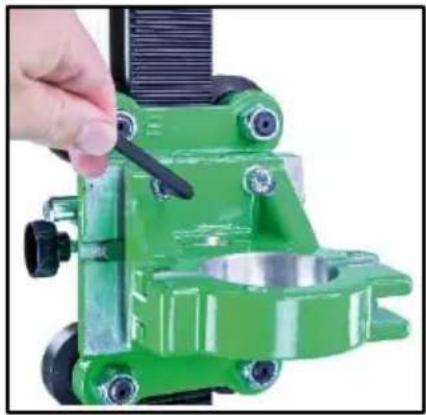
Before using the machine for the first time, the machine holder must be mounted on the carriage. To do this, place the machine holder on the keyway mount on the carriage and screw in the four M8x30 hexagon socket screws firmly using the SW6 Allen key.
Use

After each readjustment always check that the screws are tightly fixed so that safe operating of the drill rig is possible.
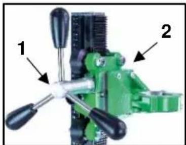
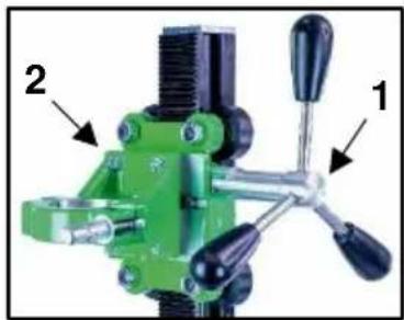
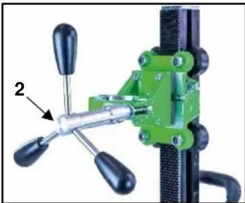
Mounting the turnstile
-
Mount the turnstile (1) on the right or left side of the carriage (2) depending on the work to be performed.
-
Check whether the turnstile (1) is fixed tightly.
Fastening of the drill rig
Hole centering indicator:
The drill rig is fitted with a hole centering indicator for easy and precise positioning.
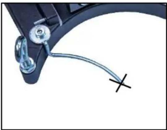
Mark the center of the hole to be drilled. Fully extend the hole centering indicator (see fig.).
Position the drill rig in such a way that the tip or the groove of the indicator points precisely to the hole center mark.
After the drill rig has been fastened, put the hole center indicator back in its original position.
Fastening by means of dowels in concrete
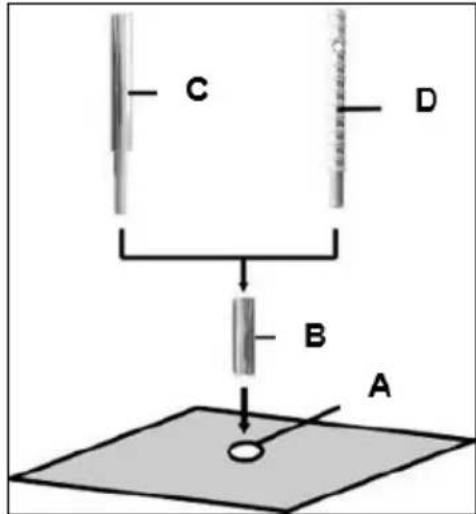
- Mark the position of the drill holes for the fastening on the surface to be drilled.
- Drill a hole (Ø 16) 50mm deep (A), into which the dowel M12 (B) is to be placed; insert and secure the dowel with the doweling tool (C).
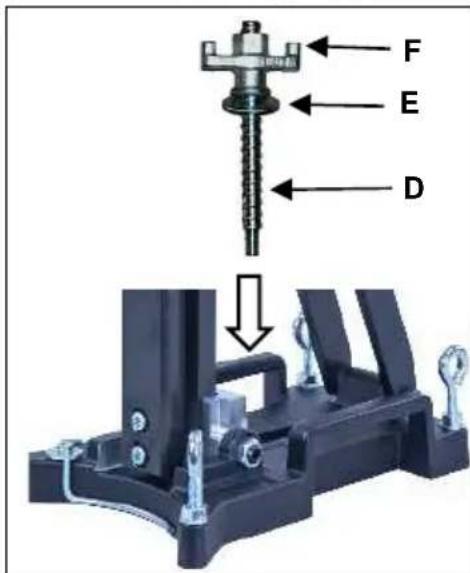
- Screw the quick action clamping screw (D) into the dowel.

For brickwork, Brickwork-dowels must be used (drillhole - 0 18mm).
Install the drill rig.
Fix the washer (E) and finally the fastening nut (F) on the quick action clamping screw (D).
- Tighten the fastening nut (F) with a wrench SW 27
Before and after tightening the nut (F), the 4 adjustable screws have to be adjusted in order to adapt the rig to the surface.

Do check whether the drill rig is installed safely and firmly.
Fastening by means of quick action bracing unit
In order to brace the drill rig by means of the quick action bracing unit, the distance to the opposite wall must be between 1,7 m and 3 m.
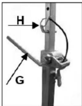
Position the drill rig. Position the quick action bracing unit as close as possible behind the support on the base of the rig. Fix the drill rig by turning the crank (G) clockwise. Secure in position by means of the appropriate bolt (H).
Attention!
It is important, that the drill rig is firmly connected to the surface. If not fixed correctly, injuries to the operator or damages to the drilling unit may be caused.
Uncontrolled movements during drilling will cause the drill bit to hit the surface to be drilled which may lead to a chipping of the segments. The drill bit might also tilt in the bore hole which consequently will damage it.
Fixing the core drill motor

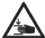

Wear protective gloves! Caution! When mounting the machine, risk of squashing!
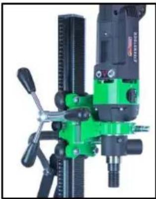
Mounting the core drill machine
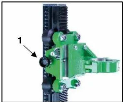
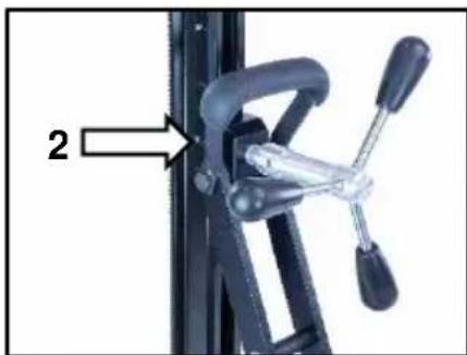
Move the machine holder far up and fix it by tightening the screw (1).
Using the feed lever (2), loosen the clamping screw and open the clamp.
Dismantle the additional handle of the machine beforehand.
Place the core drill in the holder and close the clamp using the clamping screw.
Loosen the screw (1) before drilling.
Always lock the carriage when the assembly is not in use.
For operation with the core drill machine you have to attend the operating instructions and the safety indications!
Operations
In order to operate the tool safely, please observe the following notes:
Details of the work area
- Keep the work area free of everything which could obstruct operations.
- Provide for adequate illumination of the work area.
- Adhere to the regulations concerning the power connection.
- Lay the power cable in such a way that any damage by the drill can be avoided.
- Make sure to always keep the work area in view and to be able to reach all necessary operating elements and safety installations.
- Keep other persons away from your work area in order to avoid accidents.
Space requirements for operating and maintenance
Whenever possible, keep a free space for operating and maintenance of about 2m around the drill position, so that you can work safely and have immediate access in case of a failure.
Drilling
At the beginning, drill very slowly, since the drill bit does only starts cutting with a fraction of the cut surface in the material. If you drill too fast or with too much pressure, the drill bit could get jammed.
Observe the LED in the handle of the ESD 162. If it lights red, reduce your pressing force.
Angled drilling
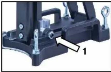
- Loosen the two side screws (1) on the base plate.
- Loosen the clamp (2) on the support with the help of the feed lever.
- Now turn the column until the desired angle.
- Tighten the 2 screws (1) and the clamp (2) again.
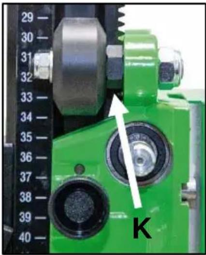
The scale on the toothed column makes adjusting the drilling angle easier.
Demounting the core drill unit


- Move the machine holder with the core drill upwards and fix it by tightening the screw (1 - page 14).
- Remove the drill bit.
- Loosen the clamping screw at the machine holder and remove the core drill machine from the drill rig. (see page 14)
- Loosen the fastening nut (F). (see page 13) While doing so, hold the drill rig firmly!
- Remove the drill rig.
- Unscrew the quick action clamping screw (D). (see page 13)
Care and maintenance
-
Always keep the drill rig clean, especially the column with the toathing and the 4 sliding rollers in the machine holder. In order to allow the free movement of the pinion shaft, it should be slightly lubricated.
-
In order to achieve a good performance of the drill rig, the 4 sliding rollers in the machine holder have to move along the column without slackness.
Attention!
After every tenth drilling you should check if the sliding pieces have got loose-fitting due to drilling vibration.
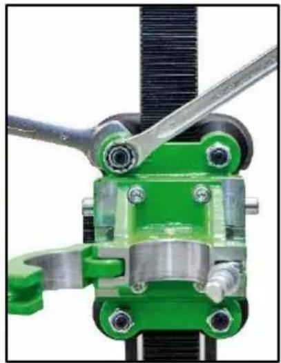
If the position has changed, it can be adjusted as follows:
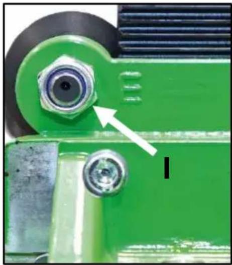
Use an open-ended spanner SW 19 to loosen the nut on the sliding roller marked E.
By slightly turning the nuts (K) with an open-ended spanner SW 19, the pressure of the sliding roller can be adjusted.
After adjusting the sliding roller, the nut (I) must be tightened again.
Behaviour at malfunction
Turn off the machine by malfunction and disconnect from the electricity network. Operations on the electrical system of the machine can be executed only by a specialist.
Trouble shooting
| Malfunction | Possible cause | Repair |
| Drill unit has too much play (vibration) | stand has been loose | adjust the wing nut |
| guidance has too much play thrust piece worn | adjust guidance (see page 16) replace the thrust piece | |
| thrust sliding rollers | replace the sliding rollers |
Warranty
According to our general terms of delivery for business dealings, suppliers have to provide to companies a warranty period of 12 months for redhibitory defects. (to be documented by invoice or delivery note).
Damage due to natural wear, overstressing or improper handling are excluded from this warranty.
Damages due to material defects or production faults shall be eliminated free of charge by either repair or replacement.
Complaints will be accepted only if the tool is returned in non-dismantled condition to the manufacturer or an authorized Eibenstock service centre.
EU - Declaration of conformity
It is necessary that the machine (e.g.: ESD 162) used in this drill rig comply with the requirements which are described in the specifications of the drill rig (f. e. drilling diameter, fixture of the motor).
We declare that this unit has been designed in compliance with 2006/42/EC.
This unit must not be put into service until it was established that the Power Tool to be connected to this unit is in compliance with 2006/42/EC (identified by the CE-marking on the Power Tool).
Subject to change without notice.
FRANCAIS
- Technical characteristics
- Available special accessories:
- Supply
- Application for indented purpose
- Mounting machine holder
- Use
- Mounting the turnstile
- Fastening of the drill rig
- Hole centering indicator:
- Fastening by means of dowels in concrete
- Fastening by means of quick action bracing unit
- Attention!
- Fixing the core drill motor
- Wear protective gloves! Caution! When mounting the machine, risk of squashing!
- Mounting the core drill machine
- For operation with the core drill machine you have to attend the operating instructions and the safety indications!
- Operations
- Details of the work area
- Space requirements for operating and maintenance
- Drilling
- Angled drilling
- Demounting the core drill unit
- Care and maintenance
- Behaviour at malfunction
- Warranty
- EU - Declaration of conformity
- FRANCAIS
Brand : Eibenstock
Model : BST 162 H
Category : Drill