
PXUG2000R - Machine tool support SCHEPPACH - Free user manual and instructions
Find the device manual for free PXUG2000R SCHEPPACH in PDF.

| Product type | Machine tool stand |
| Brand | Scheppach |
| Model | PXUG2000R |
| Dimensions (L x W x H) | 1185-2000 x 640 x 900-1000 mm |
| Table height | 815 mm |
| Extension height | 910-1020 mm |
| Support spacing (min./max.) | 1000-2000 mm |
| Max. permissible transport load | 200 kg |
| Weight | 16.7 kg |
| Intended use | For miter saws, scroll saws, table saws, etc. |
| Main functions | Machine support, workpiece support, workpiece stop, material support |
| Adjustments | Height and width of workpiece supports, support extension, adjustable support arms |
| Max. total height of mounted tool | 152 cm |
| Max. tool length | 3 m |
| Number of transport wheels | 2 |
| Number of adjustable feet | 4 |
| Maintenance and cleaning | Damp cloth with mild soap, no solvents |
| Wear parts | Adjustable support arm (ref. 4907101005) |
| Warranty | Statutory period, visible defects reported within 8 days |
| Manufacturer | Scheppach GmbH, Günzburgstraße 69, D-89335 Ichenhausen, Germany |
Frequently Asked Questions - PXUG2000R SCHEPPACH
User questions about PXUG2000R SCHEPPACH
0 question about this device. Answer the ones you know or ask your own.
Ask a new question about this device
Download the instructions for your Machine tool support in PDF format for free! Find your manual PXUG2000R - SCHEPPACH and take your electronic device back in hand. On this page are published all the documents necessary for the use of your device. PXUG2000R by SCHEPPACH.
USER MANUAL PXUG2000R SCHEPPACH

http://www.pRACTixx.com/de/service
PX-UG-2000R
| DE | Maschinenuntergestell mit Fahrvorrichtung Originalbetriebsanleitung | 6 |
| GB | Machine base frame with travel fixture Translation of original instruction manual | 14 |
| FR | Support universal mobile Traduction des instructions d'origine | 20 |
1
2
8

11
Homepage: https://www.pRACTixx.com/de/service
Explanation of the symbols on the product
| Before commissioning, read and observe the operating manual and safety instructions! | |
| Climbing prohibited! | |
| Do not exceed the maximum height! | |
| Do not exceed the maximum payload! |
Table of contents: Page:
- Introduction 15
- Product description (fig. 1-2) 15
- Scope of delivery 15
- Proper use 16
- Safety instructions 16
- Technical data 16
- Before commissioning 17
- Attachment and operation 17
- Cleaning 18
- Maintenance 18
- Repair & ordering spare parts 18
- Storage and transport 18
- Disposal and recycling. 19
1. Introduction
Manufacturer:
Scheppach GmbH
Günzburger Straße 69
D-89335 Ichenhausen
Dear Customer,
We hope your new product brings you much enjoyment and success.
Note:
In accordance with the applicable product liability laws, the manufacturer of this product assumes no liability for damage to the product or caused by the product arising from:
- Improper handling
Non-compliance with the operating manual - Repairs carried out by third parties, unauthorised specialists
- Installing and replacing non-original spare parts
Application other than specified
Note:
Read through the complete text in the operating manual before installing and commissioning the device.
This operating manual should help you to familiarise yourself with your product and to use it for its intended purpose.
The operating manual includes important instructions for the safe, proper and economic operation of the product, for avoiding danger, for minimising repair costs and downtimes and for increasing the reliability and extending the service life of the product.
In addition to the safety instructions in this operating manual, you must also observe the regulations applicable to the operation of the product in your country.
Keep the operating manual package with the power tool at all times and store it in a plastic cover to protect it from dirt and moisture. They must be read and carefully observed by all operating personnel before starting the work.
Attention
The electric power tools mounted on the tool stand may only be used by personnel who have been trained in the use of the electric power tool and who have been instructed on the associated hazards. The required minimum age must be observed.
In addition to the safety instructions in this operating manual and the separate regulations of your country, the generally recognised technical rules relating to the operation of such machines must also be observed.
We accept no liability for accidents or damage that occur due to a failure to observe this manual and the safety instructions.
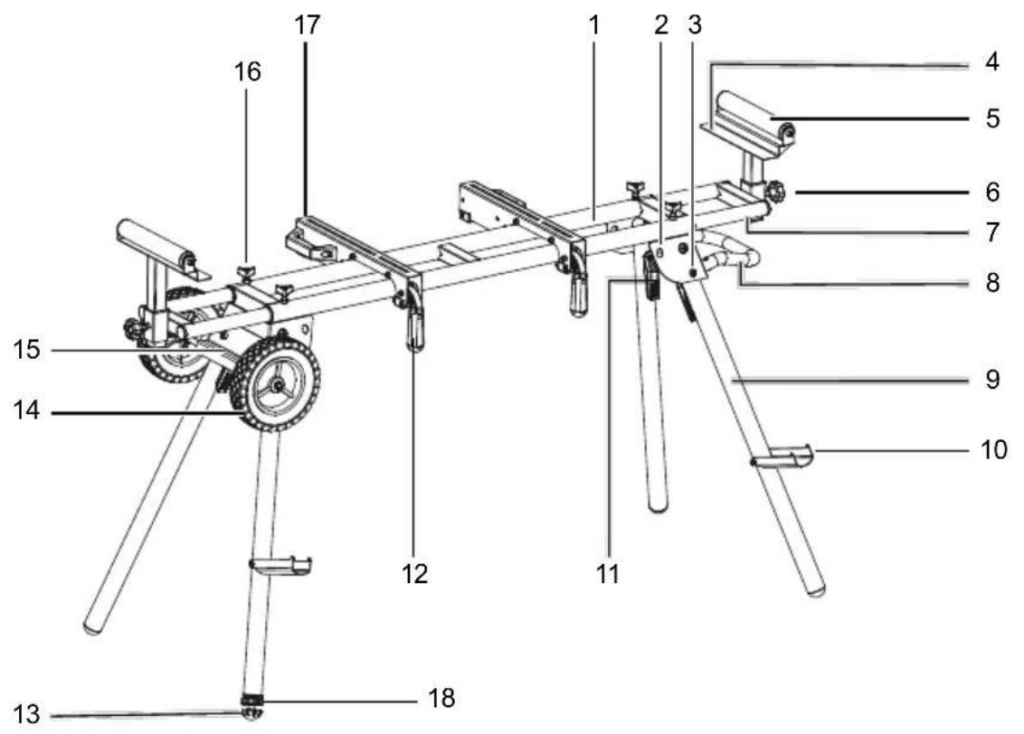
2. Product description (fig. 1 - 2)
- Tool stand
- Spring pin lock folded in
- Spring pin lock unfolded
- Workpiece stop
- Workpiece support
- Star grip screw for tool stand extension
- Tool stand extension
- Transport handle
- Frame foot
- Material support
- Spring pin locking lever
- Support arm locking lever
- Adjustable foot tip
- Transport wheel
15.Wheel axle - Grip screw
- Adjustable support arm
- Lock nut
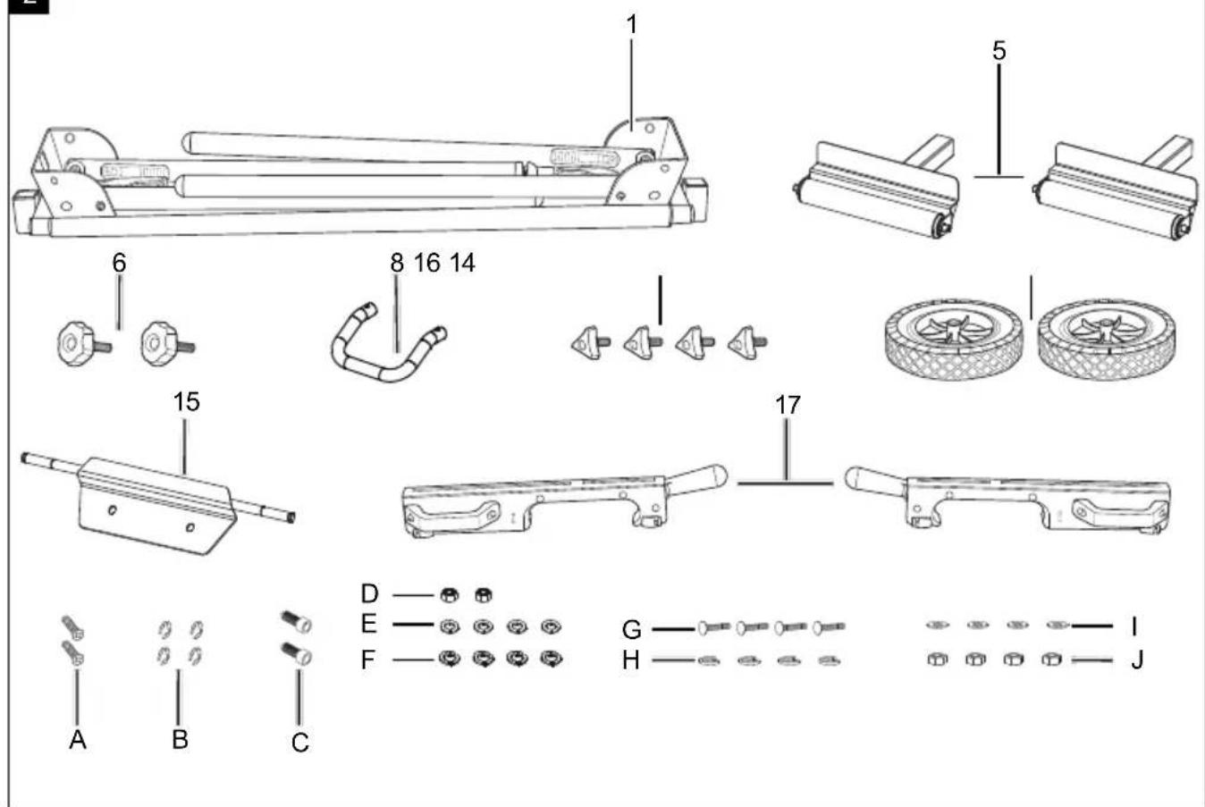
3. Scope of delivery
Item Quantity Designation
| 1 | 1x | Tool stand |
| 5 2x Workpiece support | ||
| 6 | 2x | Star grip screw for tool stand extension |
| 14 2x Transport wheels | ||
| 16 4x Grip screw | ||
| 8 1x Transport handle | ||
| 17 2x Adjustable support arm | ||
| A 2x Phillips screw M8 x 16 mm | ||
| B 4x Securing ring | ||
| C | 2x | Cylinder head screw M8 x 25 mm |
| D | 2x Locknut M8 | |
| E 4x Washer M8 | ||
F 4x Spring washer M8
G 4x Flat head screw M6 x 60 mm
H 4x Washer M6
I 4x M6 spring washers
J 4x M6 hexagonal nuts
Note:
The screws provided to fasten the machine to the universal base frame are suitable for a large number of machines. However, it is possible that these are not suitable for your machine. In this case, you will have to buy the appropriate screws yourself.
4. Proper use
Always observe the proper use of your machine base frame.
The tool stand is designed for use with tabletop devices such as litre saws, scroll saws, circular table saws, etc. Electric power tools without suitable mounting holes are not permitted to be fitted to the tool stand and must not be operated in conjunction with the tool stand.
Electric power tools must be bolted tightly to the tool stand before starting them up.
The tool stand is also designed as a workpiece support when working with cross-cut litre saws, circular table saws, and other similar electric power tools.
The maximum workpiece length is 3m
Additional workpiece supports may have to be used (e.g. a roller trestle) in order to prevent longer workpieces tilting.
Attention: Ensure that the workpiece support is secure and not tilted!
Do not use the machine base frame as a ladder or as scaffolding. Ensure that all handgrips, nuts and screws are tightened before use. Electric power tools on this product shall not exceed an overall height of 152cm . The maximum payload is 200kg . Ensure that the machine base frame is on a level, firm and stable floor.
Any use beyond this is improper use. The manufacturer is not responsible for the resultant damages, the user bears this risk alone.
Please note that our products were not designed with the intention of use for commercial or industrial purposes. We assume no guarantee if the product is used in commercial or industrial applications, or for equivalent work.
5. Safety instructions
- Only use the tool stand in conjunction with suitable electric power tools!
- Check the machine base frame for damage each time before use. Electric power tools shall not be mounted or operated on damaged support arms / crossbars.
- Electric power tools must be bolted to the support arms / crossbars and be secured on the tool stand!
- Always ensure the machine base frame is secure when setting it up.
- Always ensure that you assume a natural and safe standing position when working.
- Do not overload the machine base frame! Do not use the machine base frame for purposes for which it is not intended.
- Modifications or unauthorised changes to the tool stand and using unapproved parts is prohibited.
- All parts of the tool stand, in particular the safety devices, must be fitted correctly in order to guarantee trouble-free operation.
- Keep the tool stand out of reach of children. Store the device in a location that is inaccessible to unauthorised persons and children.
Attention!
When using electric power tools in conjunction with the tool stand, the respective machine-specific safety measures must be implemented as protection against electric shock, and the risk of injury or fire.
Read all of the instructions for the electric power tool that you intend to mount and operate before using the tool.
Safety instructions for the electric device mounted must likewise be observed.
Store these safety instructions safely.
Observe all safety instructions. If you disregard the safety instructions, you endanger yourself and others.
6. Technical data
Dimensions
1185-2000 x 640 x 900-1000
mm
Table height 815 mm
Height of the side expansions
910x1020 mm
| Min. / max. spacing of the supports | 1000-2000 mm |
| Max. permissible payload | 200 kg |
| Weight 16.7 kg |
7. Before commissioning
Make sure that the product has not been damaged during transport. Transport damage must be reported immediately to the forwarding agent that made the delivery.
- Open the packaging and carefully remove the product.
- Remove the packaging material, as well as the packaging and transport safety devices (if present).
- Check whether the scope of delivery is complete.
- Check the product and accessory parts for transport damage. In the event of complaints the carrier must be informed immediately. Later claims will not be recognised.
- If possible, keep the packaging until the expiry of the warranty period.
- When ordering please provide our article number as well as type and year of manufacture for the product.
WARNING!
The product and the packaging material are not children's toys! Do not let children play with plastic bags, films or small parts! There is a danger of choking or suffocating!
8. Attachment and operation
Attention!
Always make sure the product is fully assembled before commissioning!
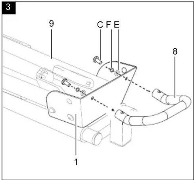
8.1 Fitting the transport handle (8) (Fig. 3)
- Place the tool stand (1) on the floor or on a workbench so that the frame legs (9) point upwards.
- Position the transport handle (8) with the holes on the outside of the tool stand (1). See Fig. (3)
- Fasten the transport handle (8) to the tool stand (1) with two M8 cylinder head screws (C), M8 spring washers (F) and M8 washers (E).
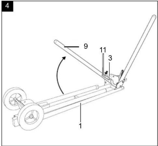
8.2 Setting the tool stand (1) up (Fig. 4+5)
- Press the spring pin locking lever (11) and fold the frame legs (9) out.
- Once the spring pin locking lever (11) latches into the intended position (3), the frame leg (9) is locked.
- Repeat this process for the other frame legs (9).
- The frame legs (9) can be adjusted for uneven surfaces.
- Place the tool stand (1) on the frame legs (9). Tum the adjustable foot tip (13) on the frame leg (9) clockwise or anti-clockwise until the tool stand (1) is securely on the floor. Lock the adjustable foot tip (13) with the lock nut (18).
- Fold in the frame legs in reverse order until the spring pin locking levers (11) are latched into the intended position (2).
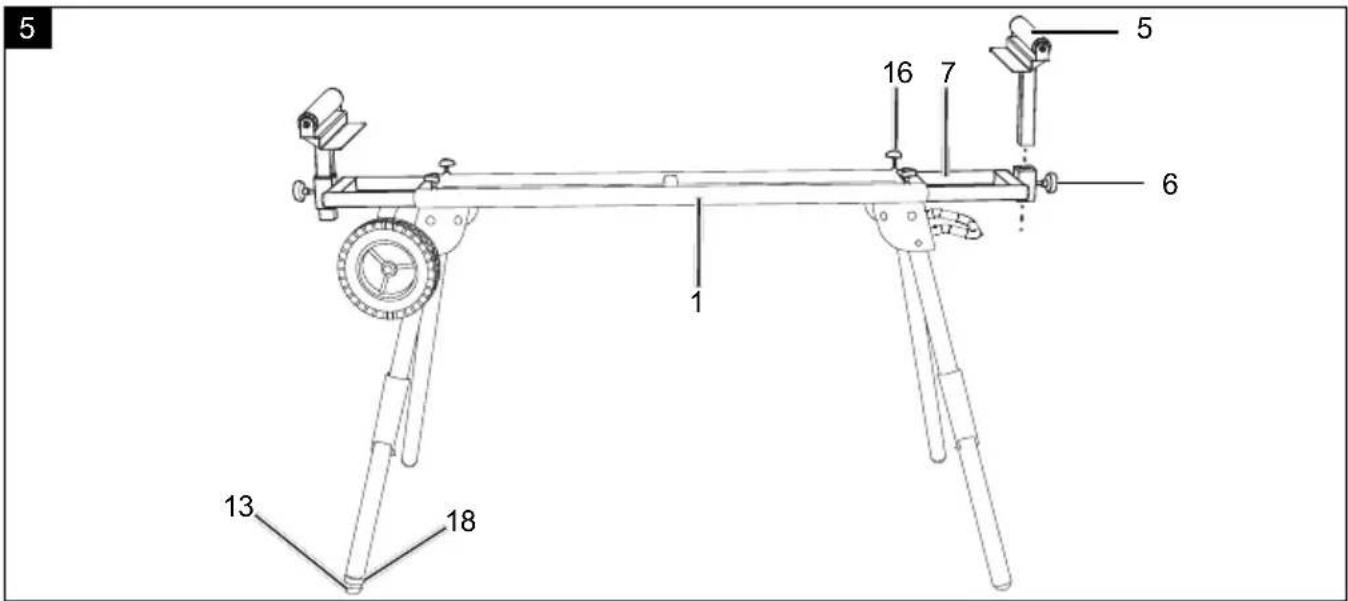
8.3 Extend the tool stand extension (7) (Fig. 5)
- The tool stand extension (7) width can be adjusted using the grip screws (16).
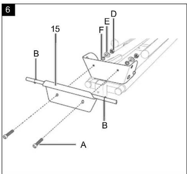
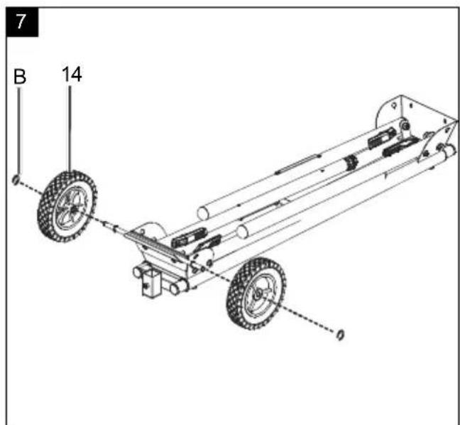
8.4 Fitting the transport wheels (14) (Fig. 6+7)
- Fit the wheel axle (15) to the machine tool stand (1) using the Phillips screws M8 (C), spring washer M8 (F), washer M8 (E) and nut M8 (D).
- Fit a safety ring (B) on both sides of the inner groove.
- Slide the transport wheel (14) onto the wheel axle (15) and secure it with a securing ring (B).
- Repeat this process with the second transport wheel (14).
8.5 Fitting the workpiece supports (5) (Fig. 5)
- Insert the workpiece support (5) into the receptacle on the tool stand (1) and use the star grip screws (6) to affix it.
- The height of the workpiece support (5) can be adjusted using the star grip screws (6).
- Repeat this process with the second workpiece support.
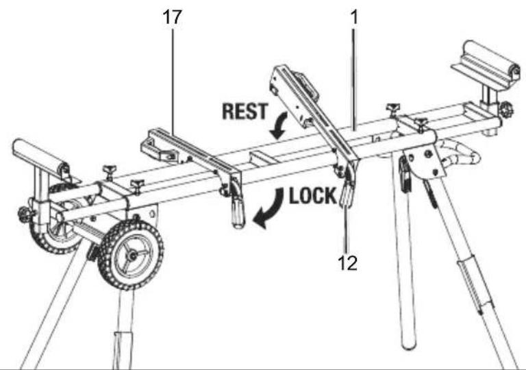
8.6 Fitting the support arms (Fig. 8)
- Fit the support arms (17) to the tool stand (1) by pulling the support arm locking lever (12) upwards and keeping it held to unlock it. Attach the support arm (17) to the grab handle side of the tool stand (1) first.
- Lower the rear of the support arm (17) down onto the tool stand (1) and press the support arm locking lever (12) down. This fixes the support arm (17) to the tool stand (1).
- Disassembly is carried out in reverse order.
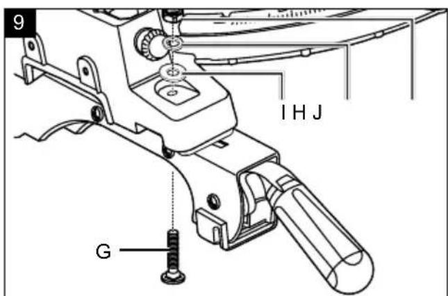
8.7 Fastening your tabletop machine (Fig. 9)
Different tabletop machines can be fastened to your tool stand (1) by adjusting the support arms (17) to the spacing of the mounting holes on your machine.
- Place your tabletop machine (e.g. cross-cut mitre saw) on the support arms (17).
- Fasten the tabletop machine with 4 flat head screws (G), 4 washers (H), 4 spring washers (I) and 4 hexagonal nuts (J) on each of the support arms (16).
- Tighten the screws after assembly.
- Fasten the support arms (17) with the mounted tabletop machine to the tool stand (1) as described in point 8.6.
8.8 Using the workpiece support (5) as a workpiece stop (Fig. 10)
The workpiece supports (5) have integrated workpiece stops (4), on both sides, which can be used to saw multiple pieces of wood to the same length.
- Loosen the star-grip screw (6) on the required side of the tool stand (1) and adjust the height of the workpiece support (5) so that the workpiece stop (4) is at the same height as the workpiece support on the saw.
- Loosen the grip screws (16) to slide the workpiece support (5) horizontally.
- Set the required distance between the saw blade and the workpiece stop (4).
- Fix your setting by retightening the handle and star grip screws (6+16).
8.9 Using the material support (10) (Fig. 10)
- The tool stand (1) has a fold-out material support (10). Fold the material support (10) down to use it.
9. Cleaning
Attention!
Before any cleaning or maintenance work, the electric power tool fitted must be switched off and the mains plug pulled out! Danger of injury!
- Keep the tool stand as free of dust and dirt as possible. Rub the tool stand clean with a clean cloth or blow it off with compressed air at low pressure.
- We recommend that you clean the tool stand directly after each use.
- Clean the device at regular intervals using a damp cloth and a little soft soap. Do not use any cleaning products or solvents; they could attack the plastic parts of the tool stand.
10. Maintenance
General maintenance tasks
- We recommend that you clean the product directly after every use.
- Clean the product at regular intervals using a damp cloth and a little soft soap. Do not use any cleaning products or solvents; they could attack the plastic parts of the product.
11. Repair & ordering spare parts
After repairs or maintenance, make sure that all safety-related parts are installed and are in perfect condition. All parts which may cause injury must be kept where they are inaccessible to children or others.
Attention: According to the German Product Liability Act, no liability is accepted for damage caused by improper repairs or by not using original spare parts.
Such work should be performed by a customer service centre or an authorised specialist. The same applies to accessory parts.
11.1 Ordering spare parts
Please provide the following information when ordering spare parts:
- Article number of the product
Service information
With this product, it is necessary to note that the following parts are subject to natural or usage-related wear, or that the following parts are required as consumables.
Wearing parts*: Adjustable support arm
- may not be included in the scope of delivery!
Spare parts / accessories
Adjustable support arm - Article no.: 4907101005
Spare parts and accessories can be obtained from our Service Centre. To do this, scan the QR code on the front page.
12. Storage and transport
Attention!
Do not transport whilst the electric power tool is running.
Before transporting the universal machine stand, pull out the mains plug of the electric power tool mounted on it! Risk of injury due to electric shock and unexpected start-up of the electric power tool!
If being transported in a vehicle, remove the electric power tool first. Ensure that the load is well secured when transporting the tool stand in a motor vehicle.
Store the product and its accessories in a dark, dry and frost-free place that is inaccessible to children. The optimum storage temperature is between 5 and 30°C .
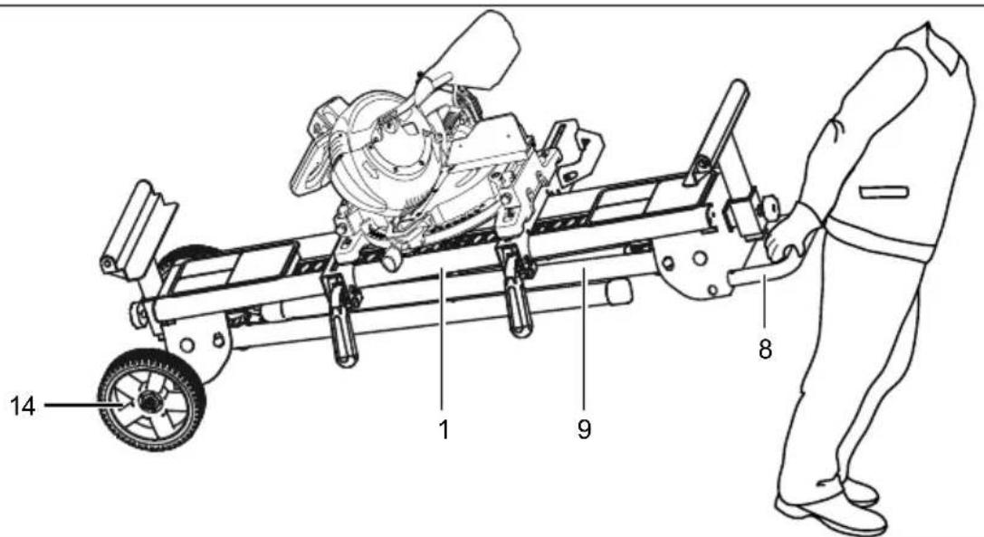
12.1 Transporting the tool stand (1) (Fig. 10)
- To transport the tool stand (1), fold the frame legs (5) in as described in point 8.2.
- The tool stand (1) can now be moved on the transport wheels (4) by holding the transport handle (10).
13. Disposal and recycling
Notes for packaging


The packaging materials are recyclable. Please dispose of packaging in an environmentally friendly manner.
Apparent defects must be notified within 8 days from the receipt of the goods. Otherwise, the buyer's rights of claim due to such defects are invalidated. We guarantee for our machines in case of proper treatment for the time of the statutory warranty period from delivery in such a way that we replace any machine part free of charge which provably becomes unusable due to faulty material or defects of fabrication within such period of time. With respect to parts not manufactured by us we only warrant insofar as we are entitled to warranty claims against the upstream suppliers. The costs for the installation of the new parts shall be borne by the buyer. The cancellation of sale or the reduction of purchase price as well as any other claims for damages shall be excluded.
Garantie FR
- EXPLANATION OF THE SYMBOLS ON THE PRODUCT
- TABLE OF CONTENTS: PAGE
- INTRODUCTION
- MANUFACTURER
- DEAR CUSTOMER
- NOTE
- ATTENTION
- PRODUCT DESCRIPTION (FIG. 1 - 2)
- SCOPE OF DELIVERY
- PROPER USE
- SAFETY INSTRUCTIONS
- TECHNICAL DATA
- BEFORE COMMISSIONING
- WARNING
- ATTACHMENT AND OPERATION
- 8.1 FITTING THE TRANSPORT HANDLE (8) (FIG. 3)
- 8.2 SETTING THE TOOL STAND (1) UP (FIG. 4+5)
- 8.3 EXTEND THE TOOL STAND EXTENSION (7) (FIG. 5)
- 8.4 FITTING THE TRANSPORT WHEELS (14) (FIG. 6+7)
- 8.5 FITTING THE WORKPIECE SUPPORTS (5) (FIG. 5)
- 8.6 FITTING THE SUPPORT ARMS (FIG. 8)
- 8.7 FASTENING YOUR TABLETOP MACHINE (FIG. 9)
- 8.8 USING THE WORKPIECE SUPPORT (5) AS A WORKPIECE STOP (FIG. 10)
- 8.9 USING THE MATERIAL SUPPORT (10) (FIG. 10)
- CLEANING
- MAINTENANCE
- GENERAL MAINTENANCE TASKS
- REPAIR & ORDERING SPARE PARTS
- 11.1 ORDERING SPARE PARTS
- SERVICE INFORMATION
- SPARE PARTS / ACCESSORIES
- STORAGE AND TRANSPORT
- 12.1 TRANSPORTING THE TOOL STAND (1) (FIG. 10)
- DISPOSAL AND RECYCLING
- GARANTIE FR
Brand : SCHEPPACH
Model : PXUG2000R
Category : Machine tool support