
PlasmaSync 60XR5 - Monitor NEC - Free user manual and instructions
Find the device manual for free PlasmaSync 60XR5 NEC in PDF.

| Product type | Plasma monitor |
| Brand | NEC |
| Model | PlasmaSync 60XR5 |
| Screen size | 60 inches (152 cm diagonal) |
| Power supply | 100-240 V, 50/60 Hz |
| Power consumption | Approximately 500 W (estimation) |
| Weight | Approximately 60 kg (estimation) |
| Video inputs | Composite video (RCA), S-Video (VIDEO1/2), Component (DVD/HD1/2), HDMI (DVD/HD3/4), PC/RGB (D-Sub 15-pin) |
| Audio inputs | AUDIO1/2/3 (RCA jacks) |
| Audio outputs | External speakers (EXT SPEAKER terminals) |
| Main functions | Digital zoom, widescreen mode (WIDE), image cropping (side-by-side and picture-in-picture), multi-screen display, remote control, sleep timer, closed captions |
| Image settings | Contrast, brightness, sharpness, color, tint, color temperature, gamma, white balance, noise reduction (NR), cinema mode, image mode (Normal, Cinema1/2, Vivid) |
| Audio settings | Bass, treble, left/right balance, audio input selection |
| Advanced settings | Image position and size, auto alignment, underscan, power saving, burn-in protection (SCREEN WIPER, INV./FD BLANC, ROTATION PIX, FOCUS LEGER) |
| External controls | RS-232C via D-Sub 9-pin connector, IR remote control |
| Menu display (OSM) | Available languages: English, German, French, Spanish, Italian, Swedish, Russian, Portuguese |
| Maintenance and cleaning | Clean the front panel and frame with a soft, dry cloth. Do not use solvents. Clean air intakes every month with a soft brush. |
| Safety | Overheat protection: automatic power cut-off in case of excessive temperature. Do not open the case. Unplug during thunderstorms. |
| Spare parts and repairability | Contact an authorized technician for any repairs. The warranty does not cover damage due to incorrect installation or improper use. |
| General information | This product contains lead or mercury. For disposal, contact local authorities or www.eiae.org. |
Frequently Asked Questions - PlasmaSync 60XR5 NEC
User questions about PlasmaSync 60XR5 NEC
0 question about this device. Answer the ones you know or ask your own.
Ask a new question about this device
Download the instructions for your Monitor in PDF format for free! Find your manual PlasmaSync 60XR5 - NEC and take your electronic device back in hand. On this page are published all the documents necessary for the use of your device. PlasmaSync 60XR5 by NEC.
USER MANUAL PlasmaSync 60XR5 NEC
(Enhanced split screen Model)
Operation Manual
Mode d'emploi
(Enhanced split screen Model)
For the specifications of your plasma monitor, refer to "Model Information".
ENGLISH
IMPORTANT SAFETY INSTRUCTIONS
Read before operating equipment
- Read these instructions.
- Keep these instructions.
- Heed all warnings.
- Follow all instructions.
- Do not use this apparatus near water.
- Clean only with a dry cloth.
- Do not block any of the ventilation openings. Install in accordance with the manufacturer's instructions.
- Do not install near any heat sources such as radiators, heat registers, stoves, or other apparatus (including amplifiers) that produce heat.
- Do not defeat the safety purpose of the polarized or grounding-type plug. A polarized plug has two blades with one wider than the other. A grounding type plug has two blades and third grounding prong. The wide blade or third prong are provided for your safety. If the provided plug does not fit into your outlet, consult an electrician for replacement of the obsolete outlet.
- Protect the power cord from being walked on or pinched particularly at plugs, convenience receptacles, and the point where they exit from the apparatus.
- Only use attachments/accessories specified by the manufacturer.
- Use of car with the cart, stand, tripod, bracket, or table specified by the manufacturer, or sold with the apparatus. When a cart is used, use caution when moving the cart/apparatus combination to avoid injury from tip-over.
- Unplug this apparatus during lightning storms or when unused for long periods of time.
- Refer all servicing to qualified service personnel. Servicing is required when the apparatus has been damaged in any way, such as power-supply cord or plug is damaged, liquid has been spilled or objects have fallen into the apparatus, the apparatus has been exposed to rain or moisture, does not operate normally, or has been dropped.
(Additional Safety Information)
- This product may contain lead or mercury. Disposal of these materials may be regulated due to environmental considerations.
For disposal or recycling information, please contact your local authorities or the Electronic Industries Alliance: www.eiae.org.
- Damage Requiring Service - The appliance should be serviced by qualified service personnel when:
A. The power supply cord or the plug has been damaged; or
B. Objects have fallen, or liquid has been spilled into the appliance; or
C. The appliance has been exposed to rain; or
D. The appliance does not appear to operate normally or exhibits a marked change in performance; or
E. The appliance has been dropped, or the enclosure damaged.
-
Tilt/Stability - All televisions must comply with recommended international global safety standards for tilt and stability properties of its cabinets design.
-
Do not compromise these design standards by applying excessive pull force to the front, or top, of the cabinet which could ultimately overturn the product.
-
Also, do not endanger yourself, or children, by placing electronic equipment/toys on the top of the cabinet. Such items could unsuspectingly fall from the top of the set and cause product damage and/or personal injury.
-
Wall Mounting - The appliance should be mounted to a wall only as recommended by the manufacturer.
- Power Lines - An outdoor antenna should be located away from power lines.
- Outdoor Antenna Grounding - If an outside antenna is connected to the receiver, be sure the antenna system is grounded so as to provide some protection against voltage surges and built up static charges.
Section 810 of the National Electric Code, ANSI/NFPA No. 70-1984, provides information with respect to proper grounding of the mats and supporting structure grounding of the lead-in wire to an antenna-discharge unit, size of grounding connectors, location of antenna-discharge unit, connection to grounding electrodes and requirements for the grounding electrode.
- Objects and Liquid Entry - Care should be taken so that objects do not fall and liquids are not spilled into the enclosure through openings.
Apparatus shall not be exposed to dripping or splashing and that no objects filled with liquids, such as vases, shall be placed on apparatus.
WARNING
To reduce the risk of fire or electric shock, do not expose this apparatus to rain or moisture.
Precautions
Please read this manual carefully before using your plasma monitor and keep the manual handy for future reference.

CAUTION
RISK OF ELECTRIC SHOCK DO NOT OPEN

CAUTION:
TO REDUCE THE RISK OF ELECTRIC SHOCK, DO NOT REMOVE COVER. NO USER-SERVICEABLE PARTS INSIDE. REFER SERVICING TO QUALIFIED SERVICE PERSONNEL.

This symbol warns the user that uninsulated voltage within the unit may have sufficient magnitude to cause electric shock. Therefore, it is dangerous to make any kind of contact with any part inside of this unit.

This symbol alerts the user that important literature concerning the operation and maintenance of this unit has been included. Therefore, it should be read carefully in order to avoid any problems.
WARNING
TO PREVENT FIRE OR SHOCK HAZARDS, DO NOT EXPOSE THIS UNIT TO RAIN OR MOISTURE. ALSO DO NOT USE THIS UNIT'S POLARIZED PLUG WITH AN EXTENSION CORD RECEPTACLE OR OTHER OUTLETS, UNLESS THE PRONGS CAN BE FULLY INSERTED. REFRAIN FROM OPENING THE CABINET AS THERE ARE HIGH-VOLTAGE COMPONENTS INSIDE. REFER SERVICING TO QUALIFIED SERVICE PERSONNEL.
Warnings and Safety Precaution
This plasma monitor is designed and manufactured to provide long, trouble-free service. No maintenance other than cleaning is required. Please see the section "Plasma monitor cleaning procedure".
The plasma display panel consists of fine picture elements (cells) with more than 99.99 percent active cells. There may be some cells that do not produce light or remain lit.
For operating safety and to avoid damage to the unit, read carefully and observe the following instructions.
To avoid shock and fire hazards:
- Provide adequate space for ventilation to avoid internal heat build-up. Do not cover rear vents or install the unit in a closed cabinet or shelves.
If you install the unit in an enclosure, make sure there is adequate space at the top of the unit to allow hot air to rise and escape. If the monitor becomes too hot, the overheat protector will be activated and the monitor will be turned off. If this happens, turn off the power to the monitor and unplug the power cord. If the room where the monitor is installed is particularly hot, move the monitor to a cooler location, and wait for 60 minutes to cool the monitor. If the problem persists, contact your dealer for service.
-
Do not use this unit's polarized plug with extension cords or outlets unless the prongs can be completely inserted.
-
Do not expose the unit to water or moisture.
-
Avoid damage to the power cord, and do not attempt to modify the power cord.
-
Unplug the power cord during electrical storms or if the unit will not be used over a long period.
-
Do not open the cabinet which has potentially dangerous high voltage components inside. If the unit is damaged in this way the warranty will be void. Moreover, there is a serious risk of electric shock.
-
Do not attempt to service or repair the unit. The manufacturer is not liable for any bodily harm or damage caused if unqualified persons attempt service or open the back cover. Refer all service to authorized Service Centers.
-
This equipment shall be connected to a MAIN outlet with a protective earth-ground connection.
-
The outlet shall be installed near the equipment and shall be easily accessible.
To avoid damage and prolong operating life:
-
Use only with 100 V to 240 V 50 Hz/60 Hz AC power supply. Continued operation at line voltages greater than 100 V to 240 V AC will shorten the life of the unit, and might even cause a fire hazard.
-
Handle the unit carefully when installing it and do not drop.
-
Set the unit away from heat, excessive dust, and direct sunlight.
-
Protect the inside of the unit from liquids and small metal objects. In case of accident, unplug the power cord and have it serviced by an authorized Service Center.
-
Do not hit or scratch the panel surface as this causes flaws on the surface of the screen.
-
For correct installation and mounting it is strongly recommended to use a trained, authorized dealer.
-
As is the case with any phosphor-based display (like a CRT monitor, for example) light output will gradually decrease over the life of a Plasma Display Panel.
-
To avoid sulfurization it is strongly recommended not to place the unit in a dressing room in a public bath or hot spring bath.
-
Do not use in a moving vehicle, as the unit could drop or topple over and cause injuries.
-
Do not place the unit on its side, upside-down or with the screen facing up or down, to avoid combustion or electric shock.
-
To prevent a fire hazard, do not place any naked flame sources (such as a lighted candle) on the equipment.
Plasma monitor cleaning procedure:
-
Use a soft dry cloth to clean the front panel and bezel area. Never use solvents such as alcohol or thinner to clean these surfaces.
-
Clean plasma ventilation areas with a vacuum cleaner with a soft brush nozzle attachment.
-
To ensure proper ventilation, cleaning of the ventilation areas must be carried out monthly. More frequent cleaning may be necessary depending on the environment in which the plasma monitor is installed.
Recommendations to avoid or minimize image retention:
Like all phosphor-based display devices and all other gas plasma displays, plasma monitors can be susceptible to image retention under certain circumstances. Certain operating conditions, such as the continuous display of a static image over a prolonged period of time, can result in image retention if proper precautions are not taken. To protect your investment in this plasma monitor, please adhere to the following guidelines and recommendations for minimizing the occurrence of image retention:
* Always enable and use your computer's screen saver function during use with a computer input source.
* Display a moving image whenever possible.
* Change the position of the menu display from time to time.
* Always power down the monitor when you are finished using it.
If the plasma monitor is in long term use or continuous operation take the following measures to reduce the likelihood of image retention:
* Lower the Brightness and Contrast levels as much as possible without impairing image readability.
* Display an image with many colors and color gradations (i.e. photographic or photo-realistic images).
* Create image content with minimal contrast between light and dark areas, for example white characters on black backgrounds. Use complementary or pastel color whenever possible.
* Avoid displaying images with few colors and distinct, sharply defined borders between colors.
Plasma monitor driving sound
The panel of the Plasma monitor is composed of extremely fine pixels and these pixels emit light according to received video signals. This principle may cause you to hear a buzz or electrical hum coming from the Plasma monitor. Also note that the rotation speed of the cooling fan motor increases when the ambient temperature of the Plasma monitor becomes high. You may hear the sound of the motor at that time.
Note:
The following items are not covered by the warranty.
- Image retention
- Panel generated sound, examples: Fan motor noise, and electrical circuit humming /glass panel buzzing.
Contact your dealer for other recommended procedures that will best suit your particular application needs.
IMPORTANT SAFETY INSTRUCTIONS
Read before operating equipment ...... En-2
Important Information ...... En-3
Contents ...... En-4
Contents of the Package ...... En-4
Options En-4
Installation En-5
Ventilation Requirements for enclosure mounting ..... En-5
Cable Management......En-6
Using the remote control En-6
Battery Installation and Replacement ...... En-6
Operating Range En-6
Part Names and Function ...... En-7
Front View En-7
Rear View/ Terminal Board En-8
Remote Control En-11
Basic Operations ...... En-12
POWER En-12
To turn the unit ON and OFF: En-12
VOLUME En-12
To adjust the sound volume: En-12
MUTE En-12
To mute the audio: En-12
DISPLAY En-12
To check the settings: En-12
DIGITAL ZOOM En-12
OFF TIMER En-12
To set the off timer: En-12
To check the remaining time: En-12
To cancel the off timer: En-12
WIDE Operations ...... En-13
Wide Screen Operation (manual) En-13
When viewing videos or digital video discs ...... En-13
Wide Screen Operation with Computer Signals ..... En-14
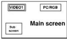
SPLIT SCREEN Operations ...... En-15
Showing a couple of pictures on the screen at the same
time En-15
Operations in the Side-by-side mode ...... En-15
Operations in the Picture-in-picture mode ...... En-16
Selecting the input signals to be displayed ...... En-16
Zooming in on a specific input ...... En-16
Adjusting the OSM controls ...... En-16
OSM (On Screen Menu) Controls ...... En-17
Menu Operations En-17
Menu Tree En-18
Picture Settings Menu En-20
Storing picture settings ...... En-20
Adjusting the picture En-20
Reducing noise in the picture ...... En-20
Setting the color temperature En-21
Adjusting the color to the desired level ...... En-21
Setting the picture to suit the movie ...... En-21
Setting the picture mode according to the brightness of
the room En-21
Changing the Gamma Curve ...... En-22
Making the Low Tone adjustments ...... En-22
Adjusting the pedestal level (black level) ...... En-22
Adjusting the colors En-22
Audio Settings Menu En-23
Adjusting the treble, bass and left/right balance and audio input select En-23
Setting the allocation of the audio and DVD/HD
connectors En-23
Image Adjust Settings Menu En-23
Adjusting the Position, Size, Fine Picture,
Picture Adj and Underscan ...... En-23
SET UP Settings Menu En-24
Setting the language for the menus ...... En-24
Checking the signal being transmitted to DVD/HD1
terminal En-24
Checking the signal being transmitted to PC/RGB terminal .... En-24
Setting high definition images to the suitable screen size .... En-24
Setting a computer image to the correct RGB select screen .... En-24
Setting the black level for HDMI signal ...... En-25
Setting the video signal format ...... En-25
Setting the background color when no signal is being input .... En-25
Setting the gray level for the sides of the screen ... En-26
Setting the screen size for S1/S2 video input ...... En-26
Turning on/off the menu display ...... En-26
Setting the position of the menu ...... En-26
Remote ID En-27
Resetting to the default values ...... En-27
Function Settings Menu En-27
Setting the menu mode ...... En-27
Setting the power management for computer images .... En-27
ON/STANDBY indicator En-28
Setting the Input Skip ...... En-28
Removing the sub screen area when there is no input signal detected for the sub screen .... En-28
Displaying the entire image during DIGITAL ZOOM operations .... En-28
Displaying still images in the sub screen ...... En-28
Reducing image retention ...... En-29
Setting Closed Caption ...... En-30
Reducing the brightness of Closed Caption ...... En-31
Setting the power on mode ...... En-31
Setting the Protocol set En-31
Signal Information Menu En-31
Checking the frequencies, polarities of input signals, and resolution ...... En-31
External Control En-32
Application En-32
Connections En-32
Type of connector: D-Sub 9-pin male ...... En-32
Communication Parameters En-32
External Control Codes (Reference) En-32
Pin Assignments ...... En-32
mini D-Sub 15-pin connector (Analog) ...... En-32
1/8 Stereo Mini Jack (not supplied) for REMOTE IN/OUT En-32
Connection with STB En-33
Troubleshooting...... En-34
Limited Warranty Plasma Monitors En-35
Contents of the Package
□ Plasma monitor (×1)
□ Power cord (×1, 3 m/9.8 feet)
□ Remote control (×1)
□ AAA Batteries (×2, Manganese battery for remote control)
□ Manuals (Model Information and Operation)
□ Ferrite cores for power cord (×2), bands for power cord (×2)
□ Ferrite core for remote cable (×2)
□ Cable clampers (×3), beads bands (×3)
Options
- Wall mount unit
- Ceiling mount unit
- Tilt mount unit
- Tabletop Stand
- Attachable speakers
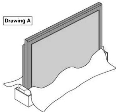
You can attach your optional mounts or stand to the plasma monitor in one of the following two ways:
* While it is upright. (See Drawing A)
* As it is laid down with the screen face down (See Drawing B). Lay the protective sheet, which was wrapped around the monitor when it was packaged, beneath the screen surface so as not to scratch the screen face.
* Do not touch or hold the screen face when carrying the unit.
- This device cannot be installed on its own. Be sure to use a stand or original mounting unit. (Wall mount unit, Stand, etc.)
- For correct installation and mounting it is strongly recommended to use a trained, authorized dealer.
Failure to follow correct mounting procedures could result in damage to the equipment or injury to the installer.
Product warranty does not cover damage caused by improper installation.
CAUTION
• Install the device following the manual of the optional unit.
• Install the device on the stable and even place where it is strong enough to stand the weight.
- Use the specified clasps for installing.
• After installation, make sure to take measurements to prevent falling.
- Make sure to move or install the device with another person(s).
* Use only a mounting kit or stand recommended by the manufacturer and listed as an accessory.
natural_image
Illustration of a flat-screen monitor mounted on a base with a wavy surface and a small container, labeled 'Drawing A' (no other text or symbols)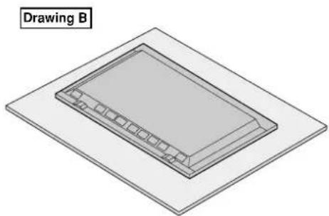
natural_image
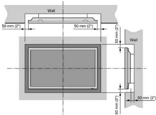
3D diagram of a rectangular object with internal grid pattern, placed on a flat base (no text or symbols)Ventilation Requirements for enclosure mounting
To allow heat to disperse, leave space between surrounding objects as shown on the diagram when installing.
text_image
Wall 50 mm (2") 50 mm (2") 50 mm (2') Wall 50 mm (2") 50 mm (2)Cable Management
Using the cable clampers and beads bands provided with the plasma display; Bundle the signal and audio cables at the back of the unit to connect to the display.
42XR5
text_image
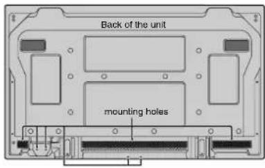
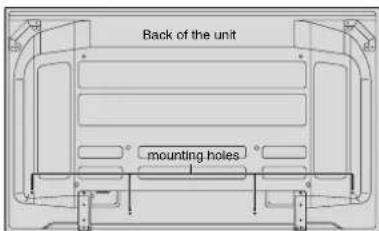
Back of the unit mounting holes50XR6
text_image
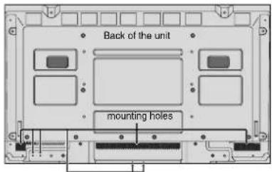
Back of the unit mounting holes60XR5
text_image
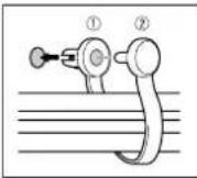
Back of the unit mounting holesTo attach
Insert ① into a mounting hole, then snap ② into the back of ① to fix the clamper.
Clampers are designed to be difficult to undo once in place. Please attach carefully. Cables can be routed to the right or left.
Bunch separated cables together and secure them with the provided beads bands.
Do not allow excessive stress to be placed on the ends of cables.
To detach
Using pliers, twist the clamper 90^ and pull it outward. In some cases the clamper may have deteriorated over time and may get damaged when removed.
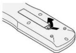
Using the remote control Battery Installation and Replacement
Designated batteries:
Please use size AAA (R03) or AAA (LR03).
Insert the 2 "AAA" batteries, making sure to set them in with the proper polarity.
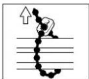
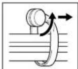
- Press and open the cover.
natural_image
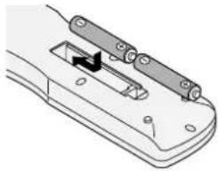
Technical line drawing of a remote control panel with mounting holes and a central arrow indicating rotation (no text or symbols)- Align the batteries according to the indication inside the case.

natural_image
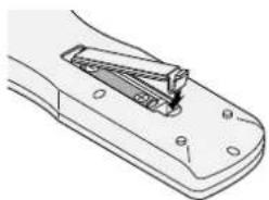
Technical line drawing of a mechanical component with a black arrow indicating a specific part (no text or symbols present)- Replace the cover.
natural_image
Technical line drawing of a mechanical clamp or bracket component (no text or symbols)Operating Range
* Use the remote control within a distance of about 7 m/23 ft. from the front of the monitor's remote control sensor and at horizontal and vertical angles of up to approximately 30°.
* The remote control operation may not function if the monitor's remote control sensor is exposed to direct sunlight or strong artificial light, or if there is an obstacle between the sensor and the remote control.
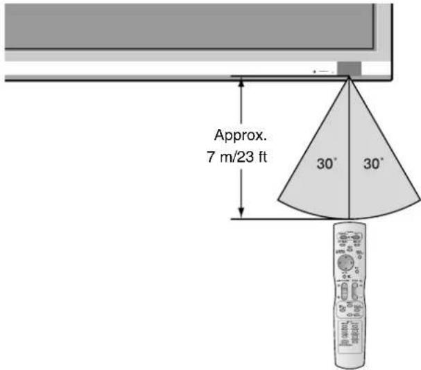
text_image
Approx. 7 m/23 ft 30° 30°CAUTION
- Use only the specified batteries.
- Make sure to insert the batteries correctly according to the indications of Ⓓ and . ⊖
- Do not drop or mishandle the remote control.
- Do not get the remote control wet. If the remote control gets wet, wipe it dry immediately.
- Avoid heat and humidity.
- When not using the remote control for a long period, remove the batteries.
- Do not use new and old batteries together, or use different types together.
- Do not take apart the batteries, heat them, or throw them into a fire.
Part Names and Function
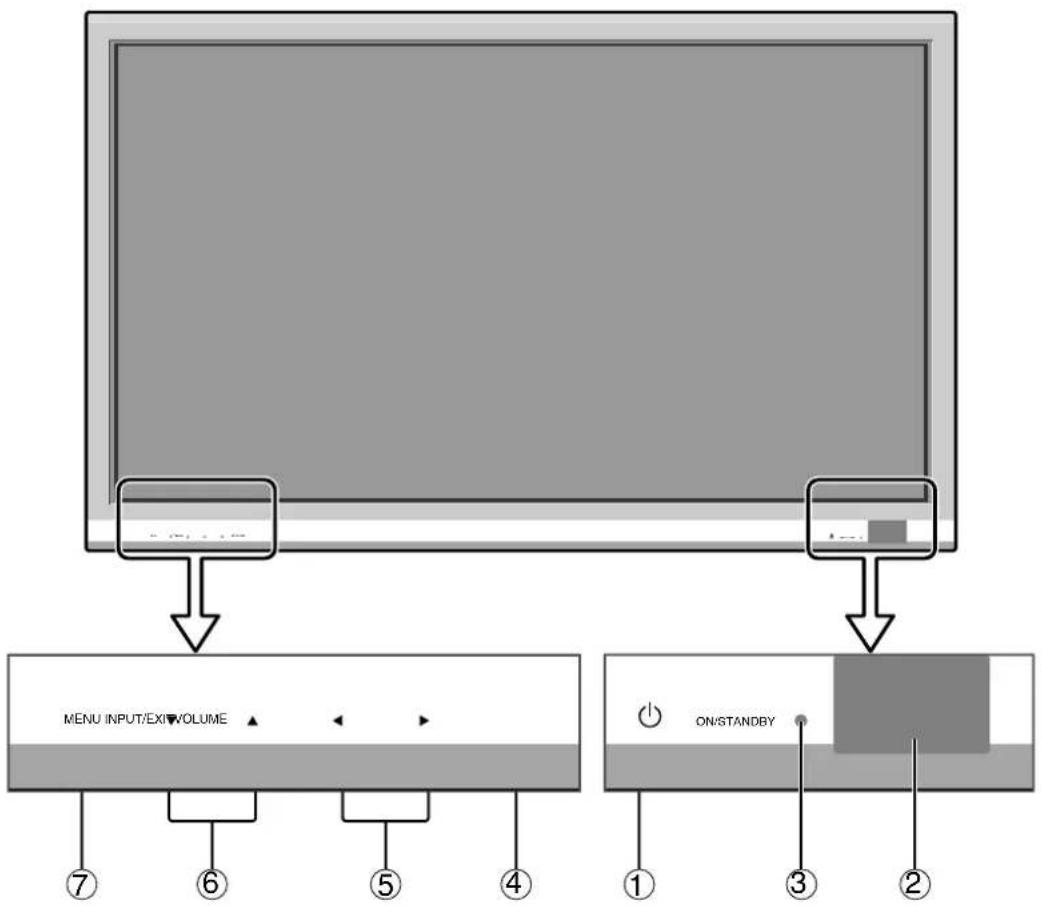
Front View
text_image
MENU INPUT/EXIT VOLUME ON/STANDBY①Power
Turns the monitor's power on and off.
②Remote sensor window
Receives the signals from the remote control.
③ON/STANDBY indicator
When the power is on .... Lights green. When the power is in the standby mode ... Lights red.
④INPUT / EXIT
Switches the input. Functions as the EXIT buttons in the On-Screen Menu (OSM) mode.
⑤ ◀ and ▶
Enlarges or reduces the image. Functions as the CURSOR (◄/►) buttons in the On-Screen Menu (OSM) mode.
⑥VOLUME ▼ and ▲
Adjusts the volume. Functions as the CURSOR (▼/▲) buttons in the On-Screen Menu (OSM) mode.
⑦MENU
Sets the On-Screen Menu (OSM) mode and displays the main menu.
WARNING
The Power on/off switch does not completely disconnect power from the display.
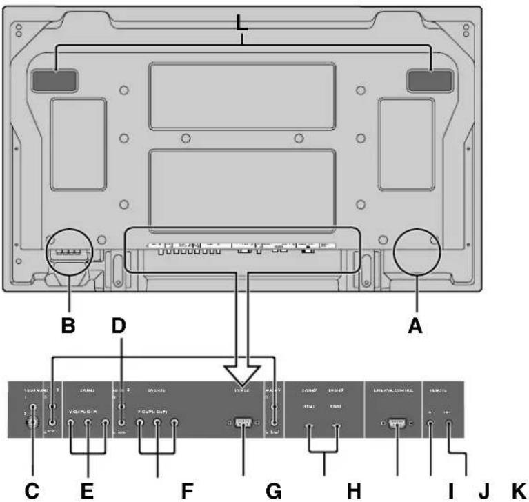
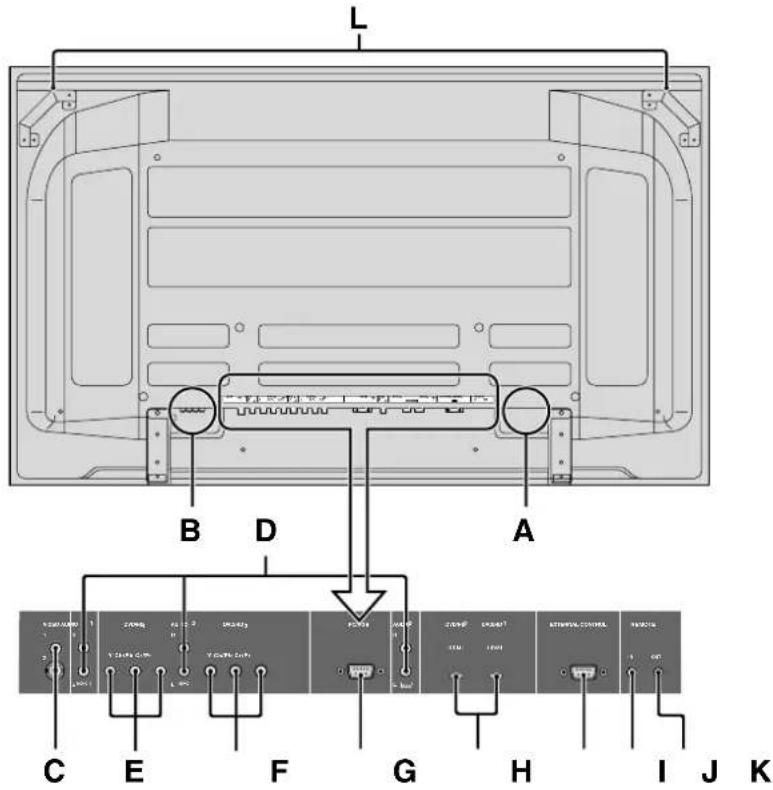
Rear View/ Terminal Board 42XR5
text_image
A B D C E F G H I J KA AC IN
Connect the included power cord here.
B EXT SPEAKER L and R
Connect speakers (optional) here. Maintain the correct polarity. Connect the ⊕ (positive) speaker wire to the ⊕ EXT SPEAKER terminal and the ⊖ negative) speaker wire to the ⊖ EXT SPEAKER terminal on both LEFT and RIGHT channels. Please refer to your speaker's owner's manual.
C VIDEO1, 2 (RCA, S-Video)
Connect VCR's, DVD's or Video Cameras, etc. here.
D AUDIO1, AUDIO2, AUDIO3
These are audio input terminals. The input is selectable. Set which video image corresponds to the audio input from the audio menu screen.
E DVD/HD1
Connect DVD's, High Definition or Laser Discs, etc. here.
F DVD/HD2
You can connect DVDs, High Definition sources, Laser Discs, etc. here.
G PC/RGB (D-Sub)
Connect an analog RGB signal from a computer, etc. here.
H DVD/HD3, DVD/HD4 (HDMI)
Connect a digital signal from a source with a HDMI output. See “Specifications” on “Model Information”.
| EXTERNAL CONTROL (D-Sub)
This terminal is used when operating and controlling the monitor externally with a control system (by RS-232C).
J REMOTE IN
K REMOTE OUT
Use these terminals to control external equipment.
L Handles
Use when installing or carrying the plasma monitor.

HDMI, the HDMI logo and High-Definition Multimedia Interface are trademarks or registered trademarks of HDMI Licensing LLC.
Rear View/ Terminal Board 50XR6
text_image
L B D A C E F G H I J KA AC IN
Connect the included power cord here.
B EXT SPEAKER L and R
Connect speakers (optional) here. Maintain the correct polarity. Connect the ⊕ (positive) speaker wire to the ⊕ EXT SPEAKER terminal and the ⊖ negative) speaker wire to the ⊖ EXT SPEAKER terminal on both LEFT and RIGHT channels. Please refer to your speaker's owner's manual.
C VIDEO1, 2 (RCA, S-Video)
Connect VCR's, DVD's or Video Cameras, etc. here.
D AUDIO1, AUDIO2, AUDIO3
These are audio input terminals. The input is selectable. Set which video image corresponds to the audio input from the audio menu screen.
E DVD/HD1
Connect DVD's, High Definition or Laser Discs, etc. here.
F DVD/HD2
You can connect DVDs, High Definition sources, Laser Discs, etc. here.
G PC/RGB (D-Sub)
Connect an analog RGB signal from a computer, etc. here.
H DVD/HD3, DVD/HD4 (HDMI)
Connect a digital signal from a source with a HDMI output. See "Specifications" on "Model Information".
| EXTERNAL CONTROL (D-Sub)
This terminal is used when operating and controlling the monitor externally with a control system (by RS-232C).
J REMOTE IN
K REMOTE OUT
Use these terminals to control external equipment.
L Handles
Use when installing or carrying the plasma monitor.

HDMI, the HDMI logo and High-Definition Multimedia Interface are trademarks or registered trademarks of HDMI Licensing LLC.
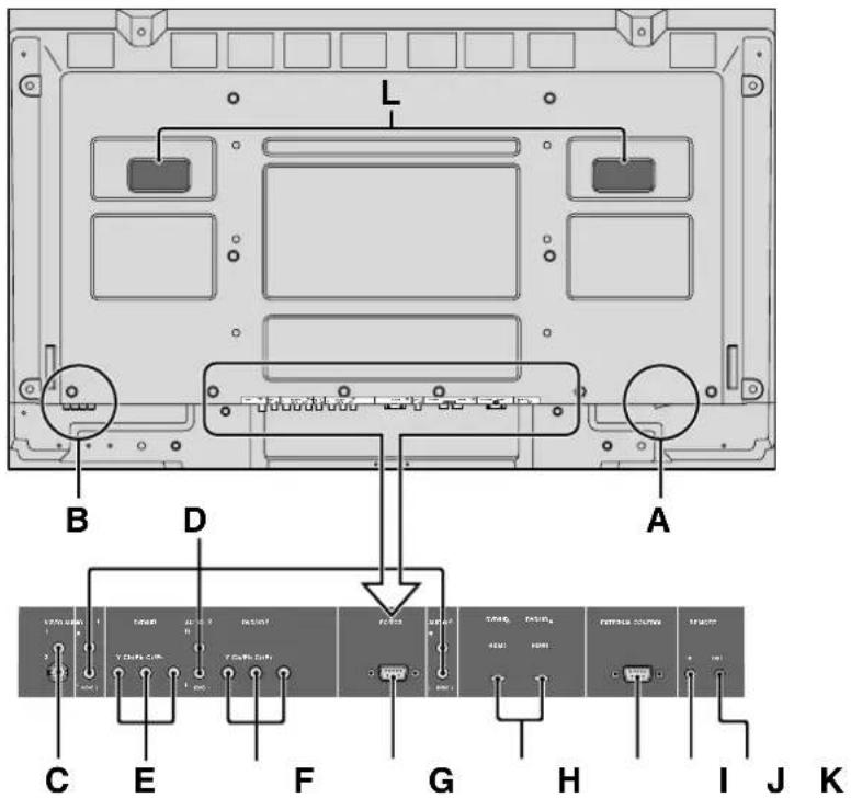
Rear View/ Terminal Board 60XR5
text_image
L B D A C E F G H I J KA AC IN
Connect the included power cord here.
B EXT SPEAKER L and R
Connect speakers (optional) here. Maintain the correct polarity. Connect the ⊕ (positive) speaker wire to the ⊕ EXT SPEAKER terminal and the ⊖ negative) speaker wire to the ⊖ EXT SPEAKER terminal on both LEFT and RIGHT channels. Please refer to your speaker's owner's manual.
C VIDEO1, 2 (RCA, S-Video)
Connect VCR's, DVD's or Video Cameras, etc. here.
D AUDIO1, AUDIO2, AUDIO3
These are audio input terminals. The input is selectable. Set which video image corresponds to the audio input from the audio menu screen.
E DVD/HD1
Connect DVD's, High Definition or Laser Discs, etc. here.
F DVD/HD2
You can connect DVDs, High Definition sources, Laser Discs, etc. here.
G PC/RGB (D-Sub)
Connect an analog RGB signal from a computer, etc. here.
H DVD/HD3, DVD/HD4 (HDMI)
Connect a digital signal from a source with a HDMI output. See "Specifications" on "Model Information".
| EXTERNAL CONTROL (D-Sub)
This terminal is used when operating and controlling the monitor externally with a control system (by RS-232C).
J REMOTE IN
K REMOTE OUT
Use these terminals to control external equipment.
L Handles
Use when installing or carrying the plasma monitor.

HDMI, the HDMI logo and High-Definition Multimedia Interface are trademarks or registered trademarks of HDMI Licensing LLC.
Remote Control

text_image
POWER STANDBY ON OFF TIMER DISPLAY WIDE POSITION /CONTROL MENU /ENTER MUTE EXIT VOLUME ZOOM + + - + - SINGLE SIDE BY SIDE PICTURE IN PICTURE ACTIVE SELECT INPUT VIDEO1 DVD/HD1 VIDEO2 DVD/HD2 PC/RGB DVD/HD3 DVD/HD4 PICTURE MEMORY 19 3 5 7 10 11 13 14 15 16 17 18① POWER ON/STANDBY
Switches the power on/standby.
(This does not operate when the ON/STANDBY indicator of the plasma is off.)
② OFF TIMER
Activates the off timer for the unit.
③ DISPLAY
Displays the source settings on the screen.
④ WIDE
Automatically detects the signal and sets the aspect ratio.
WIDE button is not active for all signals.
⑤ MENU/ENTER
Press this button to access the OSM controls.
Press this button during the display of the main menu to go to the sub menu.
⑥ CURSOR (▲/▼/◄/►)
Use these buttons to select items or settings and to adjust settings or switch the display patterns.
⑦ EXIT
Press this button to exit the OSM controls in the main menu. Press this button during the display of the sub menu to return to the previous menu.
⑧ MUTE
Mutes the audio.
⑨ VOLUME (+ /−)
Adjusts the audio volume.
⑩ ZOOM (+ /−)
Enlarges or reduces the image.
⑪ SINGLE
Cancels the split screen mode.
⑫ SIDE BY SIDE
Press this button to show a couple of pictures in the side-by-side mode.
⑬ PICTURE IN PICTURE
Press this button to show a couple of pictures in the picture-in-picture mode.
14 ACTIVE SELECT
Press this button to make the desired picture activate during split screen mode.
When the PICTURE FREEZE function is operating, this button can be used to display still images on the sub screen.
⑮ VIDEO1,2
Press this button to select VIDEO as the source.
VIDEO can also be selected using the INPUT/EXIT button on the monitor.
⑯ DVD/HD1, 2, 3, 4
Press this button to select DVD/HD as the source.
DVD/HD can also be selected using the INPUT/EXIT button on the monitor.
⑰ PC/RGB
Press this button to select PC/RGB as the source.
PC/RGB can also be selected using the INPUT/EXIT button on the monitor.
18 PICTURE MEMORY
Switches sequentially between picture memory settings 1 to 6.
19 Remote control signal transmitter
Transmits the remote control signals.
POWER
To turn the unit ON and OFF:
- Plug the power cord into an active AC power outlet.
- Press the Power button (on the unit).
The monitor's ON/STANDBY indicator turns red and the standby mode is set.
- Press the POWER ON button (on the remote control) to turn on the unit.
The monitor's ON/STANDBY indicator will light up (green) when the unit is on.
- Press the POWER STANDBY button (on the remote control) or the Power button (on the unit) to turn off the unit.
The monitor's ON/STANDBY indicator turns red and the standby mode is set (only when turning off the unit with the remote control).
VOLUME
To adjust the sound volume:
- Press and hold the VOLUME button (on the remote control or the unit) to increase to the desired level.
- Press and hold the VOLUME button (on the remote control or the unit) to decrease to the desired level.
MUTE
To mute the audio:
Press the MUTE button on the remote control to mute the audio; press again to restore.
DISPLAY
To check the settings:
- The screen changes each time the DISPLAY button is pressed.
- If the button is not pressed for approximately three seconds, the menu turns off.
DIGITAL ZOOM
Digital zoom specifies the picture position and enlarges the picture.
- (Be sure ZOOM NAV is off.)
Press the ZOOM (+ or -) button to display magnifying glass. ( 🔒 )
To change the size of the picture:
Press the ZOOM+ button and enlarge the picture.
A press of the ZOOM- button will reduce the picture and return it to its original size.
To change the picture position:
Select the position with the ▲▼◀▶ buttons.
- Press the EXIT button to delete the pointer.
OFF TIMER
To set the off timer:
The off timer can be set to turn the power off after 30, 60, 90 or 120 minutes.
- Press the OFF TIMER button to start the timer at 30 minutes.
- Press the OFF TIMER button to the desired time.
- The timer starts when the menu turns off.
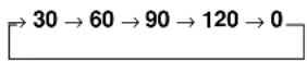
OFF TIMER 30
To check the remaining time:
- Once the off timer has been set, press the OFF TIMER button once.
- The remaining time is displayed, then turns off after a few seconds.
- When five minutes remain the remaining time appears until it reaches zero.
OFF TIMER 28
To cancel the off timer:
- Press the OFF TIMER button twice in a row.
- The off timer is canceled.
OFF TIMER 0
Note:
After the power is turned off with the off timer ...
A slight current is still supplied to the monitor. When you are leaving the room or do not plan to use the system for a long period of time, turn off the power to the monitor.
Wide Screen Operation (manual)
With this function, you can select one of seven screen sizes.
When viewing videos or digital video discs
-
Press the WIDE button on the remote control.
-
Within 3 seconds ...
Press the WIDE button again.
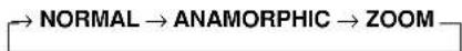
The screen size switches as follows:
→ NORMAL → ANAMORPHIC → STADIUM → ZOOM → 2.35:1 → 14:9 → UNDERSCAN
When a 720P or 1080I signal is input:
ANAMORPHIC 2.35:1
When displaying enhanced split screen:
NORMAL ANAMORPHIC
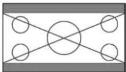
NORMAL size screen (4:3)

natural_image
Geometric diagram with four circles arranged in a cross pattern around a central circle, enclosed by diagonal lines (no text or symbols)The normal size screen is displayed.
* The picture has the same size as video pictures with a 4:3 aspect ratio.
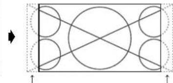
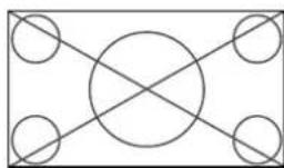
ANAMORPHIC size screen

natural_image
Pure geometric diagram with intersecting circles and diagonal lines inside a rectangle (no text or symbols)The image is expanded in the horizontal direction.
* Images compressed in the horizontal direction (“squeezed images”) are expanded in the horizontal direction and displayed on the entire screen with correct linearity. (Normal images are expanded in the horizontal direction.)
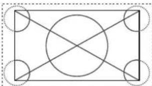
STADIUM size screen

natural_image
Geometric diagram with a central circle and four surrounding circles, no text or symbols present.The picture is expanded in the horizontal and vertical directions at different ratios.
* Use this for watching normal video programs (4:3) with a wide screen.
ZOOM size screen

natural_image
Geometric diagram with concentric circles and intersecting lines, no text or symbols presentThe picture is expanded in the horizontal and vertical direction, maintaining the original proportions.
* Use this for theater size (wide) movies, etc.
2.35:1 size screen
Original image
natural_image
Pure geometric diagram with circles and diagonal lines inside a rectangle, no text or symbols presentInformation is lost on both sides.
The squeezed film image is expanded to fulfill the entire screen at a ratio of 2.35:1. Black bands do not appear at the top and bottom but information is lost on the left and right margins.
- This feature is available when the input signal is video, component (480I, 480P, 576I, 576P, 720P, 1080I) or RGB (525P or 625P signal from a scan converter).
* If black bands appear on the top and bottom in the full size screen, select the 2.35:1 size screen to fill the screen and avoid image retention.
14:9 size screen

natural_image
Geometric diagram with a circle and two diagonal lines inside a rectangle (no text or symbols)The image is displayed at a 14:9 aspect ratio.
* This feature is available when the input signal is video, component (480I, 480P, 576I, 576P) or RGB (525P or 625P signal from a scan converter).
UNDERSCAN size screen
Set "UNDERSCAN" to "ON" in the "IMAGE ADJUST". Typical televisions crop the image (i.e., overscan). In order to restore the entire image, select UNDERSCAN.
natural_image
Pure geometric diagram with intersecting circles and quadrants, no text or symbols presentOverscan
Underscan
* Picture noise or black border may appear near the edge of screen depending on the connected component.
* The continuous display in this screen size over a prolonged period of time may result in image retention.
* When Macrovision signal is input, the brightness may change.
Note:
Do not allow 4:3 content to be displayed for extended periods of time without using gray bars. This can cause image retention.
Wide Screen Operation with Computer Signals
Switch to the wide screen mode to expand the 4:3 image to fill the entire screen.
-
Press the WIDE button on the remote control.
-
Within 3 seconds ...
Press the WIDE button again.
The screen size switches as follows:
When displaying enhanced split screen:
NORMAL ↔ ANAMORPHIC
NORMAL size screen (4:3 or SXGA 5:4)

natural_image
Geometric pattern with four circles and diagonal lines forming a cross (no text or symbols)The picture has the same size as the normal computer image.
ANAMORPHIC size screen

natural_image
Geometric diagram with intersecting circles and diagonal lines inside a rectangle (no text or symbols)The image is expanded in the horizontal direction.
ZOOM size screen

When wide signals are input.
ANAMORPHIC size screen

Information
■ Supported resolution
See page En-3 of Model Information for details on the display output of the various VESA signal standards supported by the monitor.
■ When 852 (848) dot × 480 line wide VGA* signals with a vertical frequency of 60 Hz and horizontal frequency of 31.7 (31.0) kHz are input
Select an appropriate setting for RGB SELECT mode referring to the "Table of Signals Supported" on page En-3 of Model Information.
* "VGA", "SVGA" and "SXGA" are registered trademarks of IBM, Inc. of the United States.
Note:
Do not allow 4:3 content to be displayed for extended periods of time without using gray bars. This can cause image retention.
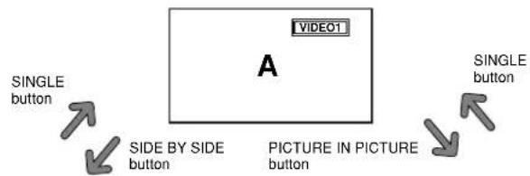
SPLIT SCREEN Operations
Showing a couple of pictures on the screen at the same time
* There may be some RGB-input signals that may not be displayed as not all signals are supported.
1. Press the button to select a screen mode from among single mode, side-by-side, and picture-in-picture.
flowchart
graph TD
    A["VIDEO1"] --> B["SINGLE button"]
    A --> C["SIDE BY SIDE button"]
    A --> D["PICTURE IN PICTURE button"]
    A --> E["SINGLE button"]
SIDE BY SIDE button
PICTURE IN PICTURE button
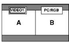
Note:
Picture A and B on the above screen are not always of the same height.
Information
Split screen operations may not function depending on the combination of input signals. In the table below, "○" means Yes, "×" means No.
■ Split screen operations may not function depending on the frequency of the RGB signals.
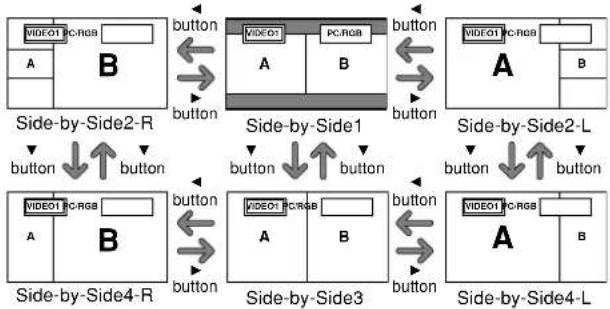
Operations in the Side-by-side mode
To change the picture size, press the cursor ◀▶ or ▼ button.
flowchart
graph TD
    subgraph Side-by-Side2_R
        A["VIDEO1 PC-RGB"] --> B["button"]
        B --> C["PC-RGB"]
        C --> D["button"]
    end

    subgraph Side-by-Side1
        E["VIDEO1 PC-RGB"] --> F["button"]
        F --> G["PC-RGB"]
        G --> H["button"]
    end

    subgraph Side-by-Side2_L
        I["VIDEO1 PC-RGB"] --> J["button"]
        J --> K["PC-RGB"]
        K --> L["button"]
    end

    subgraph Side-by-Side3
        M["VIDEO1 PC-RGB"] --> N["button"]
        N --> O["PC-RGB"]
        O --> P["button"]
    end

    subgraph Side-by-Side4_L
        Q["VIDEO1 PC-RGB"] --> R["button"]
        R --> S["PC-RGB"]
        S --> T["button"]
    end
To swap the picture on the right and the left, press the cursor ▲ button.
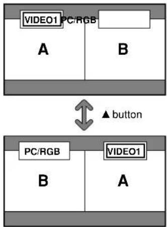
text_image
VIDEO1 PC/RGB A B ▲ button PC/RGB B ATo make the desired picture active, press the ACTIVE SELECT button.
flowchart
graph TD
    subgraph State_A
        A1["VIDEO1 PC/RGB"] --> A2["A"]
        A2 --> B2["B"]
    end
    subgraph State_B
        B1["VIDEO1 PC/RGB"] --> B2
    end
    A1 <--> A2
    B1 <--> B2
    A1 -->|ACTIVE SELECT button| B2
    style State_A fill:#f9f,stroke:#333
    style State_B fill:#bbf,stroke:#333
Operations in the Picture-in-picture mode
To move the position of the sub screen, press the cursor◀ or ▶ button.
To change the size of the sub screen, press the ▼ button.
flowchart
graph TD
    A1["VIDEO1"] -->|button| B1["PC/RGB"]
    A2["VIDEO1"] -->|button| B2["PC/RGB"]
    A3["VIDEO1"] -->|button| B3["PC/RGB"]
    A4["VIDEO1"] -->|button| B4["PC/RGB"]
    A5["VIDEO1"] -->|button| B5["PC/RGB"]
    A6["VIDEO1"] -->|button| B6["PC/RGB"]
    A7["VIDEO1"] -->|button| B7["PC/RGB"]
    A8["VIDEO1"] -->|button| B8["PC/RGB"]
    A9["VIDEO1"] -->|button| B9["PC/RGB"]
To make the desired picture active, press the ACTIVE SELECT button.
flowchart
graph LR
    subgraph Left
        A1["VIDEO1 PC/RGB"] --> B1["B"]
        A2["A"] --> B1
    end
    subgraph Right
        B1 <-->|ACTIVE SELECT button| B2["B"]
        B2 --> B3["VIDEO1 PC/RGB"]
        B3 --> A4["A"]
Selecting the input signals to be displayed
- Press the ACTIVE SELECT button to make the desired picture active.
- Press the PC/RGB, VIDEO1, 2 or DVD/HD1, 2, 3, 4 button to change the selection of the input signal.
The INPUT/EXIT button on the monitor can also be used to change the selection.
Zooming in on a specific input
- Press the ACTIVE SELECT button to make the desired picture active.
- Use the ZOOM (+ or -) button to enlarge the picture. For details, see "DIGITAL ZOOM" on page En-12.
Adjusting the OSM controls
- Press the ACTIVE SELECT button to make the desired picture active.
- Press the MENU/ENTER button to display the MAIN MENU.
- Adjust the setting to your preference. For details, see “OSM (On Screen Menu) Controls” on page En-17.
Note:
During enhanced split screen, some functions of OSM controls are not available.
Menu Operations
The following describes how to use the menus and the selected items.
- Press the MENU/ENTER button on the remote control to display the MAIN MENU.
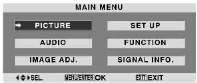
text_image
MAIN MENU PICTURE AUDIO IMAGE ADJ. SET UP FUNCTION SIGNAL INFO. SEL. ADQUENTER OK EXIT EXIT- Press the cursor buttons ▲ ▼ on the remote control to highlight the menu you wish to enter.
- Press the MENU/ENTER button on the remote control to select a sub menu or item.
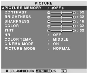
text_image
PICTURE ● PICTURE MEMORY : OFF CONTRAST : 52 BRIGHTNESS : 32 SHARPNESS : 16 COLOR : 32 TINT : 32 NR : OFF COLOR TEMP. : MIDDLE CINEMA MODE : ON PICTURE MODE : NORMAL SEL AD RETURN MENU ENTER OK EXIT- Adjust the level or change the setting of the selected item by using the cursor buttons ◀ ▶ on the remote control.

text_image
CONTRAST : 10- The adjustments or settings are then stored in memory. The change is stored until another change is made.
- Repeat steps 2 - 5 to adjust an additional item, or press the EXIT button on the remote control to return to the main menu.
* When adjusting using the bar at the bottom of the screen, press the ◀ or ▶ button within 5 seconds. If not, the current setting is stored and the previous screen appears.
Note: The main menu disappears by pressing the EXIT button.
Information
■ Advanced menu mode
When “ADVANCED OSM” is set to “ON” in the FUNCTION menu, full menu items will be shown.
text_image
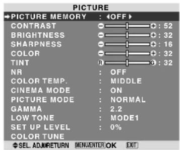
PICTURE ● PICTURE MEMORY : OFF CONTRAST : 52 BRIGHTNESS : 32 SHARPNESS : 16 COLOR : 32 TINT : 32 NR : OFF COLOR TEMP. : MIDDLE CINEMA MODE : ON PICTURE MODE : NORMAL GAMMA : 2.2 LOW TONE : MODE1 SET UP LEVEL : 0% COLOR TUNE SEL ADJ RETURN MENU ENTER OK EXIT* The actual screen may be different from the ones in this manual.
Menu Tree
: Shaded areas indicate the default value.
-←→+: Press the ◀ or ▶ button to adjust.
☐: Menu items in a ruled box are available when the ADVANCED OSM is set to ON.
| Main menu Sub menu 2 Sub menu 3 Sub menu 4 RESET | REFERENCE | |||||
| PICTURE PICTURE MEMORY OFF/MEMORY1-6 YES En-20 | ||||||
| CONTRAST | ←→+ 0←52→72 | YES | En-20 | |||
| BRIGHTNESS | ←→+ 0←32→64 | YES | En-20 | |||
| SHARPNESS | ←→+ 0←16→32 | YES | En-20 | |||
| COLOR | ←→+ 0←32→64 | YES | En-20 | |||
| TINT | R←→G 0←32→64 | YES | En-20 | |||
| NR OFF/NR-1/NR-2/NR-3 | YES En-20 | |||||
| COLOR TEMP. | LOW/MIDDLE LOW/MIDDLE/HIGH | YES | En-21 | |||
| WHITE BALANCE | GAIN RED | ←→+ 0←40→70 | YES | En-21 | ||
| GAIN GREEN | ←→+ 0←40→70 | YES | En-21 | |||
| GAIN BLUE | ←→+ 0←40→70 | YES | En-21 | |||
| BIAS RED | ←→+ 0←40→70 | YES | En-21 | |||
| BIAS GREEN | ←→+ 0←40→70 | YES | En-21 | |||
| BIAS BLUE | ←→+ 0←40→70 | YES | En-21 | |||
| RESET | OFF←→ON | YES En-21 | ||||
| CINEMA MODE | ON←→OFF | YES | En-21 | |||
| PICTURE MODE | DEFAULT/THEATER1/THEATER2/NORMAL/BRIGHT | YES | En-21 | |||
| GAMMA | 2.1←→2.2←→2.3←→2.4 | YES | En-22 | |||
| LOW TONE*3 | MODE1←→MODE2 | YES En-22 | ||||
| SET UP LEVEL | 0%←→3.75%←→7.5% | YES | En-22 | |||
| COLOR TUNE | RED | Y←→M 0←32→64 | YES | En-22 | ||
| GREEN | C←→Y 0←32→64 | YES | En-22 | |||
| BLUE | M←→C 0←32→64 | YES | En-22 | |||
| YELLOW | G←→R 0←32→64 | YES | En-22 | |||
| MAGENTA | R←→B 0←32→64 | YES | En-22 | |||
| CYAN | B←→G 0←32→64 | YES | En-22 | |||
| RESET | OFF←→ON | YES | En-22 | |||
| Main menu Sub menu 2 Sub menu 3 Sub menu 4 RESET | REFERENCE | |||||
| AUDIO | BASS | ←→+ 0←13→26 | YES | En-23 | ||
| TREBLE | ←→+ 0←13→26 | YES | En-23 | |||
| BALANCE | L←→R -22←0→+22 | YES | En-23 | |||
| AUDIO INPUT1 | VIDEO 1-2 / DVD/HD 1-4 / PC/RGB | YES En-23 | ||||
| AUDIO INPUT2 | VIDEO 1-2 / DVD/HD 1-4 / PC/RGB | YES En-23 | ||||
| AUDIO INPUT3 | VIDEO 1-2 / DVD/HD 1-4 / PC/RGB | YES En-23 | ||||
| DVD/HD3 INPUT | INPUT 1-3 / HDMI | YES En-23 | ||||
| DVD/HD4 INPUT | INPUT 1-3 / HDMI | YES En-23 | ||||
| Main menu Sub menu 2 Sub menu 3 Sub menu 4 RESET | REFERENCE | |||||
| IMAGE ADJ. | ASPECT MODE | ZOOM/NORMAL/ANAMORPHIC/STADIUM/14:9/2.35:1/UNDERSCAN | — | En-23 | ||
| V-POSITION | ←→+ -64←0→+64 | YES | En-23 | |||
| H-POSITION | ←→+ -128←0→+127 | YES | En-23 | |||
| V-HEIGHT | ←→+ 0←→64 | YES | En-23 | |||
| H-WIDTH | ←→+ 0←→64 | YES | En-23 | |||
| AUTO PICTURE | ON←→OFF*2 | NO En-23 | ||||
| FINE PICTURE*1 | ←→+ *2 0←→64 | YES En-23 | ||||
| PICTURE ADJ.*1 | ←→+ *2 0←→64 | YES En-23 | ||||
| UNDERSCAN | ON←→OFF | YES | En-23 | |||
| Main menu Sub menu 2 Sub menu 3 Sub menu 4 RESET | REFERENCE | |||||
| SET UP | LANGUAGE | ENGLISH/DEUTSCH/FRANÇAIS/ESPAÑOL/ITALIANO/SVENSKA/PYCCKIЙ/PORTUGUÊS | NO | En-24 | ||
| DVD/HD1 INPUT | COMPONENT | YES En-24 | ||||
| D-SUB INPUT | RGB | YES En-24 | ||||
| HD SELECT | 1080/1035/540P | NO | En-24 | |||
| RGB SELECT AUTO | YES En-24 | |||||
| HDMI SET UP | LOW←→HIGH | NO | En-25 | |||
| COLOR SYSTEM | AUTO/3.58NTSC/4.43 NTSC/PAL/PAL 60/PAL-N/PAL-M/SECAM | NO | En-25 | |||
| BACK GROUND | BLACK/GRAY | YES | En-25 | |||
| GRAY LEVEL | 0←...→3←...→15 | YES En-26 | ||||
| S1/S2 | AUTO←→OFF | YES | En-26 | |||
| DISPLAY OSM | ON←→OFF | YES | En-26 | |||
| OSM ADJ. | TOP LEFT←→TOP CENTER←→TOP RIGHT←→BTM LEFT←→BTM CENTER←→BTM RIGHT | YES | En-26 | |||
| REMOTE ID | ALL←→1←...→4 | YES En-27 | ||||
| ALL RESET | ON←→OFF | — | En-27 | |||
| Main menu Sub menu Sub menu 2 Sub menu 3 Sub menu 4 RESET | REFERENCE | |||||
| FUNCTION ADVANCED OSM ON←→OFF YES En-27 | ||||||
| POWER MGT. ON←→OFF YES En-27 | ||||||
| INPUT SKIP ON←→OFF YES En-28 | ||||||
| SUB. PICTURE SUB. P DETECT OFF←→AUTO YES En-28 | ||||||
| DISPLAY FADE←→NORMAL | YES En-28 | |||||
| SUB. P RATE | 20%←···→100% | YES En-28 | ||||
| ZOOM NAV | OFF←→S BY S←→BTM LEFT←→BTM RIGHT←→TOP RIGHT←→TOP LEFT | YES | En-28 | |||
| PICTURE FREEZE | OFF←→S BY S1←→S BY S2←→BTM LEFT←→BTM RIGHT←→TOP RIGHT←→TOP LEFT | YES | En-28 | |||
| PDP SAVER | MANUAL/AUTO | PEAK BRIGHT | 100%/75%/50%/25% | YES En-29 | ||
| ORBITER | OFF/AUTO1/AUTO2 | YES En-29 | ||||
| INVERSE/WHITE | OFF/INVERSE/WHITE | YES En-30 | ||||
| SCREEN WIPER | ON/OFF | YES En-30 | ||||
| SOFT FOCUS OFF/LEVEL1-4 | YES En-30 | |||||
| OSM ORBITER | ON/OFF | YES En-30 | ||||
| OSM CONTRAST | LOW/NORMAL | YES En-30 | ||||
| CLOSED CAPTION | OFF/CAPTION1-4/TEXT1-4 | YES En-30 | ||||
| CAPTION CONT | LOW/NORMAL | YES En-31 | ||||
| PWR. ON MODE | INPUT | LAST / VIDEO 1-2 / DVD/HD 1-4 / PC/RGB / MULTI | YES | En-31 | ||
| VOLUME LAST←→0← | ···→42 | YES En-31 | ||||
| PROTOCOL SET ON←→OFF YES En-31 | ||||||
| Main menu Sub menu Sub menu 2 Sub menu 3 Sub menu 4 RESET | REFERENCE | |
| SIGNAL INFO. | — | En-31 |
*1 Only when AUTO PICTURE is OFF.
*2 PC/RGB only
*3 "LOW TONE" is only for 50 inch type.
Information
■ Restoring the factory default settings
Select "ALL RESET" under the SET UP menu. Note that this also restores other settings to the factory defaults.
Picture Settings Menu
Storing picture settings
This function allows you to store in memory the current input signal and PICTURE menu settings and to recall these settings when necessary.
There are six picture memories, and notes of up to 15 characters can be added to each.
Example: Storing picture settings at MEMORY1
On "PICTURE MEMORY" of "PICTURE" menu, select "MEMORY1", then press the MENU/ENTER button.
The "PICTURE MEMORY" screen appears.
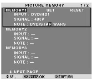
text_image
PICTURE MEMORY 1 / 2 MEMORY1 SET RESET INPUT : DVD/HD1 SIGNAL : 480P NOTE : DVD/STAR WARS MEMORY2 INPUT : — SIGNAL : — NOTE : — MEMORY3 INPUT : — SIGNAL : — NOTE : — ↓ NEXT PAGE SEL. COMPONENTS OK EXTRETURN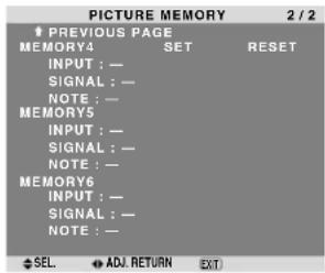
text_image
PICTURE MEMORY 2 / 2 ↑ PREVIOUS PAGE MEMORY4 SET RESET INPUT : - SIGNAL : - NOTE : - MEMORY5 INPUT : - SIGNAL : - NOTE : - MEMORY6 INPUT : - SIGNAL : - NOTE : - SEL ADJ. RETURN EXTInformation
■ PICTURE MEMORY Settings
OFF: Picture memory not used.
MEMORY1 to 6: Picture memory with the specified number used. Maximum memories are 6, not depending on inputs.
■ Setting the memory
- Use the ▲ and ▼ button to select the desired memory place, MEMORY1 to MEMORY6.
- Use the ◀ and ▶ buttons to select “SET”, then press the MENU/ENTER button.
- If necessary, input a note.
■ Resetting the memory
Use the ▲ and ▼ button to select the desired memory place, MEMORY1 to MEMORY6, then use the ◀ and ▶ buttons to select “RESET”, and finally press the MENU/ENTER button.
The memory is cleared, and “—” is displayed in the “INPUT”, “SIGNAL” and “NOTE” columns.
■ Inputting notes
- Use the ◀ and ▶ buttons to select “NOTE”, then press the MENU/ENTER button.
- Input the note.
Use the ▲ and ▼ button to select the character.
Use the ◀ and ▶ buttons to move the cursor.
Use the EXIT button to delete the character at the cursor position.
- When you have finished inputting the note, press the MENU/ENTER button.
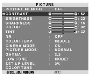
Adjusting the picture
The contrast, brightness, sharpness, color and tint can be adjusted as desired.
Example: Adjusting the contrast
On “CONTRAST” of “PICTURE” menu, adjust the contrast.
text_image
PICTURE PICTURE MEMORY : OFF CONTRAST : 52 BRIGHTNESS : 32 SHARPNESS : 16 COLOR : 32 TINT : 32 NR : OFF COLOR TEMP. : MIDDLE CINEMA MODE : ON PICTURE MODE : NORMAL GAMMA : 2.2 LOW TONE : MODE1 SET UP LEVEL : 0% COLOR TUNE SEL ADJ RETURN EXIT
text_image
: CONTRAST : 10Note: If "CAN NOT ADJUST" appears ...
When trying to enter the PICTURE submenu, make sure PICTURE MODE is not set to DEFAULT.
Information
■ Picture adjustment screen
CONTRAST: Changes the picture's white level.
BRIGHTNESS: Changes the picture's black level.
SHARPNESS: Changes the picture's sharpness. Adjusts picture detail of VIDEO display.
COLOR: Changes the color density.
TINT: Changes the picture's tint. Adjust for natural colored skin, background, etc.
■ Adjusting the computer image
Only the contrast and brightness can be adjusted when a computer signal is connected.
■ Restoring the factory default settings
Select "DEFAULT" under the "PICTURE MODE" settings.
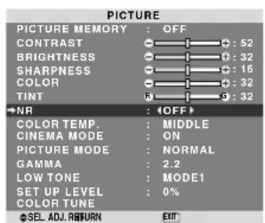
Reducing noise in the picture
Use these settings if the picture has noise due to poor reception or when playing video tapes on which the picture quality is poor.
Example: Setting "NR-3"
On "NR" of "PICTURE" menu, select "NR-3".
text_image
PICTURE PICTURE MEMORY : OFF CONTRAST : 52 BRIGHTNESS : 32 SHARPNESS : 16 COLOR : 32 TINT : 9 : 32 ←NR : OFF> COLOR TEMP. : MIDDLE CINEMA MODE : ON PICTURE MODE : NORMAL GAMMA : 2.2 LOW TONE : MODE1 SET UP LEVEL : 0% COLOR TUNE SEL ADJ RETURN EXIT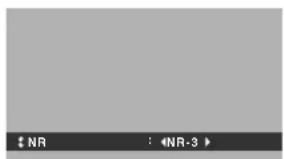
text_image
NR : NR-3Information
NR
* "NR" stands for Noise Reduction.
* This function reduces noise in the picture.
■ Types of noise reduction
There are three types of noise reduction. Each has a different level of noise reduction.
The effect becomes stronger as the number increases (in the order NR-1 → NR-2 → NR-3).
OFF: Turns the noise reduction function off.
Setting the color temperature
Use this procedure to set color tone produced by the plasma display.
Example: Setting "HIGH"
On "COLOR TEMP." of "PICTURE" menu, select "HIGH".
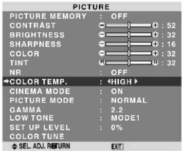
text_image
PICTURE PICTURE MEMORY : OFF CONTRAST : 52 BRIGHTNESS : 32 SHARPNESS : 16 COLOR : 32 TINT : 32 NR : OFF COLOR TEMP. : HIGH CINEMA MODE : ON PICTURE MODE : NORMAL GAMMA : 2.2 LOW TONE : MODE1 SET UP LEVEL : 0% COLOR TUNE SEL. ADJ. RETURN EXITInformation
■ Setting the color temperature
LOW: More red
MIDDLE LOW: Slightly red
MIDDLE: Standard (slightly bluer)
HIGH: More blue
Adjusting the color to the desired level
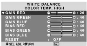
Use this procedure to adjust the white balance for each color temperature to achieve the desired color quality.
Example: Adjusting the "GAIN RED" of "HIGH" color temperature
On “COLOR TEMP.” of “PICTURE” menu, select “HIGH”, then press the MENU/ENTER button.
The "WHITE BALANCE" screen appears.
On "GAIN RED", adjust the white balance.
text_image
WHITE BALANCE COLOR TEMP. HIGH GAIN RED : 20 GAIN GREEN : 40 GAIN BLUE : 40 BIAS RED : 40 BIAS GREEN : 40 BIAS BLUE : 40 RESET : OFF SEL. ADJ. RETURN
text_image
GAIN RED 0 : 20Information
■ Adjusting the white balance
GAIN R/G/B: White balance adjustment for white level BIAS R/G/B: White balance adjustment for black level RESET: Resets settings to the factory default values.
Use ◀ and ▶ buttons to select “ON”, then press the MENU/ENTER button.
■ Restoring the factory default settings
Select "RESET" under the WHITE BALANCE menu.
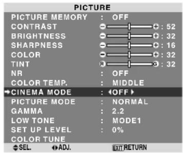
Setting the picture to suit the movie
The film image is automatically discriminated and projected in an image mode suited to the picture.
[NTSC, PAL, PAL60, 480I (60 Hz), 525I (60 Hz), 576I (50 Hz), 625I (50 Hz), 1035I (60 Hz), 1080I (60 Hz) only]
Example: Setting the "CINEMA MODE" to "OFF"
On "CINEMA MODE" of "PICTURE" menu, select "OFF".
text_image
PICTURE PICTURE MEMORY : OFF CONTRAST : 52 BRIGHTNESS : 32 SHARPNESS : 16 COLOR : 32 TINT : 32 NR : OFF COLOR TEMP. : MIDDLE CINEMA MODE : OFF PICTURE MODE : NORMAL GAMMA : 2.2 LOW TONE : MODE1 SET UP LEVEL : 0% COLOR TUNE SEL ADJ EXT RETURNInformation
CINEMA MODE
ON: Automatic discrimination of the image and projection in cinema mode.
OFF: Cinema mode does not function.
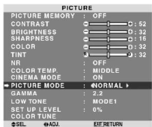
Setting the picture mode according to the brightness of the room
There are four picture modes that can be used effectively according to the environment in which you are viewing the display.
Example: Setting the "THEATER1" mode
On “PICTURE MODE” of “PICTURE” menu, select “THEATER1”.
text_image
PICTURE PICTURE MEMORY : OFF CONTRAST : 52 BRIGHTNESS : 32 SHARPNESS : 16 COLOR : 32 TINT : 32 NR : OFF COLOR TEMP. : MIDDLE CINEMA MODE : ON → PICTURE MODE : NORMAL > GAMMA : 2.2 LOW TONE : MODE1 SET UP LEVEL : 0% COLOR TUNE SEL ADJ. EXIT RETURN
text_image
PICTURE MODE : THEATER1Information
■ Types of picture modes
THEATER1, 2: Set this mode when watching video in a dark room.
This mode provides darker, finer pictures, like the screen in movie theaters.
For a darker image, select THEATER2.
NORMAL: Set this mode when watching video in a bright room.
BRIGHT: This mode provides brighter pictures than NORMAL.
This mode provides dynamic pictures with distinct differences between light and dark sections.
DEFAULT: Use this to reset the picture to the factory default settings.
ISF-DAY and ISF-NIGHT: This mode is displayed only when an ISF dealer performs a maintenance. Please contact NEC Corporation of America for details.
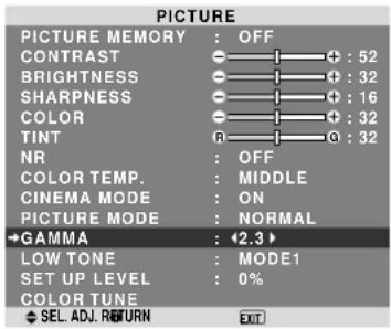
Changing the Gamma Curve
This feature adjusts the brightness of the midtone areas while keeping shadows and highlights unchanged.
Example: Setting "2.3"
Set "ADVANCED OSM" to "ON" in the FUNCTION menu. On "GAMMA" of "PICTURE" menu, select "2.3".
text_image
PICTURE PICTURE MEMORY : OFF CONTRAST : 52 BRIGHTNESS : 32 SHARPNESS : 16 COLOR : 32 TINT : 32 NR : OFF COLOR TEMP. : MIDDLE CINEMA MODE : ON PICTURE MODE : NORMAL →GAMMA : 2.3 LOW TONE : MODE1 SET UP LEVEL : 0% COLOR TUNE SEL. ADJ. RETURN EXITInformation
■ GAMMA settings
The picture becomes darker as the number increases (in the sequence of 2.1, 2.2, 2.3, 2.4).
* These values are approximate.
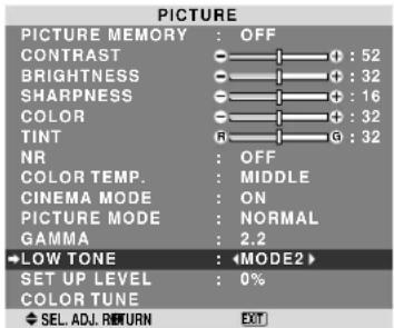
Making the Low Tone adjustments
You can select the tone reproduction from 2 modes.
This function is effective especially for dark images.
* This function is available only for 50 inch type.
Example: Setting "MODE2"
Set “ADVANCED OSM” to “ON” in the FUNCTION menu. On “LOW TONE” of “PICTURE” menu, select “MODE2”.
text_image
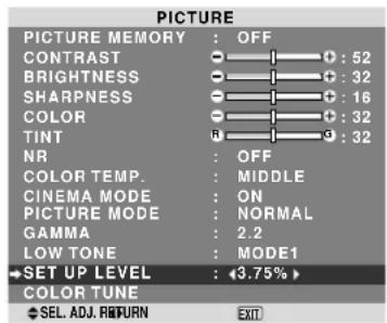
PICTURE PICTURE MEMORY : OFF CONTRAST : 52 BRIGHTNESS : 32 SHARPNESS : 16 COLOR : 32 TINT : 32 NR : OFF COLOR TEMP. : MIDDLE CINEMA MODE : ON PICTURE MODE : NORMAL GAMMA : 2.2 LOW TONE : ◀MODE2 SET UP LEVEL : 0% COLOR TUNE SEL. ADJ. RETURN EXITAdjusting the pedestal level (black level)
This feature adjusts the video black level in a video image.
Example: Setting "3.75%"
Set "ADVANCED OSM" to "ON" in the FUNCTION menu.
On "SET UP LEVEL" of "PICTURE" menu, select "3.75%".
text_image
PICTURE PICTURE MEMORY : OFF CONTRAST : 52 BRIGHTNESS : 32 SHARNESS : 16 COLOR : 32 TINT : 9 : 32 NR : OFF COLOR TEMP. : MIDDLE CINEMA MODE : ON PICTURE MODE : NORMAL GAMMA : 2.2 LOW TONE : MODE1 →SET UP LEVEL : 3.75% COLOR TUNE SEL. ADJ. RETURN EXITInformation
■ SET UP LEVEL settings
0%: Normal status
3.75%: 3.75 % lower than normal
7.5%: 7.5 % lower than normal
Adjusting the colors
Use this procedure to adjust hue and color density for red, green, blue, yellow, magenta and cyan without changing the white point.
You can accentuate the green color of trees, the blue of the sky, etc.
Example: Adjusting the color tune for blue
Set "ADVANCED OSM" to "ON" in the FUNCTION menu. On "PICTURE" menu, select "COLOR TUNE", then press the MENU/ENTER button.
The "COLOR TUNE" screen appears.
On "BLUE" of "COLOR TUNE", adjust the color tune.
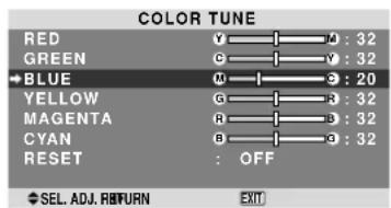
text_image
COLOR TUNE RED Y : 32 GREEN G : 32 →BLUE M : 20 YELLOW G : 32 MAGENTA R : 32 CYAN B : 32 RESET : OFF SEL. ADJ. RETURN EXITInformation
■ COLOR TUNE settings
RED: Adjusts hue of Red
GREEN: Adjusts hue of Green
BLUE: Adjusts hue of Blue
YELLOW: Adjusts hue of Yellow
MAGENTA: Adjusts hue of Magenta
CYAN: Adjusts hue of Cyan
RESET: Resets settings to the factory default value.
Use ◀ and ▶ buttons to select “ON”, then press the MENU/ENTER button.
Audio Settings Menu
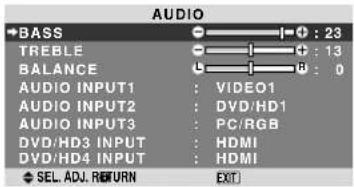
Adjusting the treble, bass and left/right balance and audio input select
The treble, bass and left/right balance can be adjusted to suit your tastes.
Example: Adjusting the bass
On "BASS" of "AUDIO" menu, adjust the bass.
text_image
AUDIO BASS TREBLE BALANCE AUDIO INPUT1 : VIDEO1 AUDIO INPUT2 : DVD/HD1 AUDIO INPUT3 : PC/RGB DVD/HD3 INPUT : HDMI DVD/HD4 INPUT : HDMI SEL. ADJ. RETURN EXITNote : If "CAN NOT ADJUST" appears...
Set "AUDIO INPUT" on the AUDIO menu correctly.
Information
■ Audio settings menu
BASS: Controls the level of low frequency sound.
TREBLE: Controls the level of high frequency sound.
BALANCE: Controls the balance of the left and right channels.
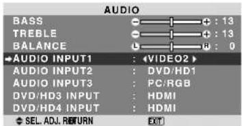
Setting the allocation of the audio and DVD/HD connectors
Setting the AUDIO1-3 and DVD/HD3-4 connectors to the desired input.
Example: Setting "AUDIO INPUT1" to "VIDEO2"
On "AUDIO INPUT1" of "AUDIO" menu, select "VIDEO2".
The available sources depend on the settings of input.
text_image
AUDIO BASS TREBLE BALANCE AUDIO INPUT1 AUDIO INPUT2 AUDIO INPUT3 DVD/HD3 INPUT DVD/HD4 INPUT SEL. ADJ. RETURN VIDEO2 DVD/HD1 PC/RGB HDMI HDMI EXTInformation
An input cannot be selected as the channel for more than one input terminal.
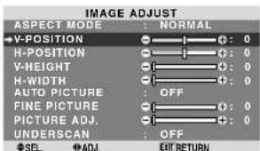
Image Adjust Settings Menu
Adjusting the Position, Size, Fine Picture, Picture Adj and Underscan
The position of the image can be adjusted and flickering of the image can be corrected.
Example: Adjusting the vertical position in the normal mode
On "V-POSITION" of "IMAGE ADJUST" menu, adjust the position.
The mode switches as follows each time the ◀ or ▶ button is pressed:
NORMAL ↔ ANAMORPHIC
* The mode can also be switched by pressing the WIDE button on the remote control.
* The settings on the IMAGE ADJUST menu are not preset at the factory.
text_image
IMAGE ADJUST ASPECT MODE : NORMAL V-POSITION : 0 H-POSITION : 0 V-HEIGHT : 0 H-WIDTH : 0 AUTO PICTURE : OFF FINE PICTURE : 0 PICTURE ADJ. : 0 UNDERSCAN : OFF SEL ADJ. EXIT RETURN
text_image
V-POSITION : -30Information
■ When "AUTO PICTURE" is "OFF"
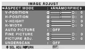
text_image
IMAGE ADJUST ASPECT MODE : ANAMORPHIC V-POSITION : 0 H-POSITION : 0 V-HEIGHT : 0 H-WIDTH : 0 AUTO PICTURE : OFF FINE PICTURE : 0 PICTURE ADJ. : 0 UNDERSCAN : OFF SEL. ADJ. RETURN EXITWhen Auto Picture is off, the Fine Picture and the Picture ADJ. items are displayed so that you can adjust them.
■ Adjusting the Auto Picture
ON: The Picture ADJ., Fine Picture and Position adjustments are made automatically.
Not available for digital ZOOM.
OFF: The Picture ADJ., Fine Picture and Position adjustments are made manually.
* If FINE PICTURE can't be adjusted, set Auto Picture to OFF and adjust manually.
■ Adjusting the position of the image
V-POSITION: Adjusts the vertical position of the image.
H-POSITION: Adjusts the horizontal position of the image.
V-HEIGHT: Adjusts the vertical size of the image. (Not available for STADIUM mode)
H-WIDTH: Adjusts the horizontal size of the image. (Not available for STADIUM mode)
FINE PICTURE*: Adjusts for flickering.
PICTURE ADJ.*: Adjusts for striped patterns on the image (i.e. vertical banding).
* The Picture ADJ. and Fine Picture features are available only when the “Auto Picture” is off.
* The AUTO PICTURE, FINE PICTURE and PICTURE ADJ. are available only for PC/RGB signals.
But, these features are not available for moving pictures on VIDEO, DVD/HD or PC/RGB.
■ Setting the Underscan
Set "ADVANCED OSM" to "ON" in the FUNCTION menu.
ON: UNDERSCAN can be selected in ASPECT MODE.
OFF: UNDERSCAN cannot be selected in ASPECT MODE.
* Selectable only when video signal is input.
SET UP Settings Menu
Setting the language for the menus
The menu display can be set to one of eight languages.
Example: Setting the menu display to "DEUTSCH"
On "LANGUAGE" of "SET UP" menu, select "DEUTSCH".
| SET UP | |
| +LANGUAGE | : ◆DEUTSCH ▶ |
| DVD/HD1 INPUT | : COMPONENT |
| D-SUB INPUT | : RGB |
| HD SELECT | : 1080I |
| RGB SELECT | : AUTO |
| HDMI SET UP | : HIGH |
| COLOR SYSTEM | : AUTO |
| BACK GROUND | : GRAY |
| GRAY LEVEL | : 3 |
| S1/S2 | : OFF |
| DISPLAY OSM | : ON |
| OSM ADJ | : TOP LEFT |
| REMOTE ID | : ALL |
| ALL RESET | : OFF |
| SEL. ADJ. RETURN | EXT |
Information
■ Language settings
ENGLISH ..... English ITALIANO ..... Italian
DEUTSCH..... German SVENSKA .....Swedish
FRANÇAIS ..... French РУССКИЙ.....Russian
ESPAÑOL ..... Spanish PORTUGUÊS ..... Portuguese
Checking the signal being transmitted to DVD/HD1 terminal
Set "ADVANCED OSM" to "ON" in the FUNCTION menu. Use this to confirm the signal being transmitted to DVD/HD1 terminal.
It is set to COMPONENT and can not be adjusted.
| SET UP | |
| LANGUAGE | : ENGLISH |
| +DVD/HD1 INPUT | : COMPONENT |
| D-SUB INPUT | : RGB |
| HD SELECT | : 1080I |
| RGB SELECT | : AUTO |
| HDMI SET UP | : HIGH |
| COLOR SYSTEM | : AUTO |
| BACK GROUND | : GRAY |
| GRAY LEVEL | : 3 |
| S1/S2 | : OFF |
| DISPLAY OSM | : ON |
| OSM ADJ. | : TOP LEFT |
| REMOTE ID | : ALL |
| ALL RESET | : OFF |
CAN NOT ADJUST
Checking the signal being transmitted to PC/RGB terminal
Set "ADVANCED OSM" to "ON" in the FUNCTION menu. Use this to confirm the signal being transmitted to the PC/RGB terminal.
It is set to RGB and can not be adjusted.
| SET UP | |
| LANGUAGE | : ENGLISH |
| DVD/HD1 INPUT | : COMPONENT |
| +D-SUB INPUT | : RGB |
| HD SELECT | : 1080I |
| RGB SELECT | : AUTO |
| HDMI SET UP | : HIGH |
| COLOR SYSTEM | : AUTO |
| BACK GROUND | : GRAY |
| GRAY LEVEL | : 3 |
| S1/S2 | : OFF |
| DISPLAY OSM | : ON |
| OSM ADJ. | : TOP LEFT |
| REMOTE ID | : ALL |
| ALL RESET | : OFF |
CAN NOT ADJUST
Setting high definition images to the suitable screen size
Use this procedure to set whether the number of vertical lines of the input high definition image is 1080I or 1035I or 540P.
Example: Setting the "HD SELECT" mode to "1035I"
Set "ADVANCED OSM" to "ON" in the FUNCTION menu.
On "HD SELECT" of "SET UP" menu, select "1035I".
| SET UP | |
| LANGUAGE | : ENGLISH |
| DVD/HD1 INPUT | : COMPONENT |
| D-SUB INPUT | : RGB |
| HD SELECT | : 10351 |
| RGB SELECT | : AUTO |
| HDMI SET UP | : HIGH |
| COLOR SYSTEM | : AUTO |
| BACK GROUND | : GRAY |
| GRAY LEVEL | : 3 |
| S1/S2 | : OFF |
| DISPLAY OSM | : ON |
| OSM ADJ. | : TOP LEFT |
| REMOTE ID | : ALL |
| ALL RESET | : OFF |
| SEL. ADJ. RETURN | EXIT |
Information
■ HD SELECT modes
These 3 modes are not displayed in correct image automatically.
1080l: Standard digital broadcasts
1035l: Japanese "High Vision" signal format
540P: Special Digital broadcasts (for example : DTC100)
Setting a computer image to the correct RGB select screen
With the computer image, select the RGB Select mode for a moving image such as (video) mode, wide mode or digital broadcast.
Example: Setting the "RGB SELECT" mode to "852×480"
Set "ADVANCED OSM" to "ON" in the FUNCTION menu.
On "RGB SELECT" of "SET UP" menu, select "852×480".
| SET UP | |
| LANGUAGE | : ENGLISH |
| DVD/HD1 INPUT | : COMPONENT |
| D-SUB INPUT | : RGB |
| HD SELECT | : 1080I |
| →RGB SELECT | : (852×480) |
| HDMI SET UP | : HIGH |
| COLOR SYSTEM | : AUTO |
| BACK GROUND | : GRAY |
| GRAY LEVEL | : 3 |
| S1/S2 | : OFF |
| DISPLAY OSM | : ON |
| OSM ADJ. | : TOP LEFT |
| REMOTE ID | : ALL |
| ALL RESET | : OFF |
| SEL ADJ RETURN | EXIT |
Information
RGB SELECT modes
AUTO: Select the suitable mode for the specifications of input signals as listed in the table “Computer input signals supported by this system” on page En-3 of Model Information.
The others: The available resolutions are shown.
See page En-3 of Model Information for the details of the above settings.
Setting the black level for HDMI signal
Set the black level.
Example: Setting the "HDMI SET UP" mode to "LOW"
Set "ADVANCED OSM" to "ON" in the FUNCTION menu.
On "HDMI SET UP" of "SET UP" menu, select "LOW".
| SET UP | |
| LANGUAGE | : ENGLISH |
| DVD/HD1 INPUT | : COMPONENT |
| D-SUB INPUT | : RGB |
| HD SELECT | : 1080I |
| RGB SELECT | : AUTO |
| HDMI SET UP | : LOW |
| COLOR SYSTEM | : AUTO |
| BACK GROUND | : GRAY |
| GRAY LEVEL | : 3 |
| S1/S2 | : OFF |
| DISPLAY OSM | : ON |
| OSM ADJ. | : TOP LEFT |
| REMOTE ID | : ALL |
| ALL RESET | : OFF |
| SEL ADJ RETURN | EXIT |
Information
■ HDMI SET UP settings
LOW: When connected to the PC signal.
HIGH: When connected to the SET TOP BOX, DVD etc. Change “HIGH” into “LOW” if the black level appears gray.
Setting the video signal format
Use these operations to set the color systems of composite video signals or Y/C input signals.
Example: Setting the color system to "3.58 NTSC"
Set "ADVANCED OSM" to "ON" in the FUNCTION menu. On "COLOR SYSTEM" of "SET UP" menu, select "3.58NTSC".
| SET UP | |
| LANGUAGE | : ENGLISH |
| DVD/HD1 INPUT | : COMPONENT |
| D-SUB INPUT | : RGB |
| HD SELECT | : 1080I |
| RGB SELECT | : AUTO |
| HDMI SET UP | : HIGH |
| →COLOR SYSTEM | : ◀3.58NTSC |
| BACK GROUND | : GRAY |
| GRAY LEVEL | : 3 |
| S1/S2 | : OFF |
| DISPLAY OSM | : ON |
| OSM ADJ. | : TOP LEFT |
| REMOTE ID | : ALL |
| ALL RESET | : OFF |
| SEL ADJ. RETURN | EXIT |
Information
■ Video signal formats
Different countries use different formats for video signals.
Set to the color system used in your current country.
AUTO: The color systems are automatically identified and the format is set accordingly.
PAL: This is the standard format used mainly in the United Kingdom and Germany.
SECAM: This is the standard format used mainly in France and Russia.
4.43 NTSC, PAL60: This format is used for videos in countries using PAL and SECAM video signals.
3.58 NTSC: This is the standard format used mainly in the United States and Japan.
PAL-M: This is the standard format used mainly in Brazil.
PAL-N: This is the standard format used mainly in Argentina.
Setting the background color when no signal is being input
The color displayed on the background when there is no signal can be set to gray.
Example: Setting "BACK GROUND" to "BLACK"
Set "ADVANCED OSM" to "ON" in the FUNCTION menu. On "BACK GROUND" of "SET UP" menu, select "BLACK".
| SET UP | |
| LANGUAGE | : ENGLISH |
| DVD/HD1 INPUT | : COMPONENT |
| D-SUB INPUT | : RGB |
| HD SELECT | : 1080I |
| RGB SELECT | : AUTO |
| HDMI SET UP | : HIGH |
| COLOR SYSTEM | : AUTO |
| BACK GROUND | : BLACK |
| GRAY LEVEL | : 3 |
| S1/S2 | : OFF |
| DISPLAY OSM | : ON |
| OSM ADJ. | : TOP LEFT |
| REMOTE ID | : ALL |
| ALL RESET | : OFF |
| SEL ADJ RETURN | EXIT |
Information
■ BACK GROUND Settings
BLACK: Sets the background color to black.
GRAY: Sets the background color to gray.
Setting this makes it easier to see that there is no signal.
Setting the gray level for the sides of the screen
Use this procedure to set the gray level for the parts on the screen on which nothing is displayed when the screen is set to the 4:3 size.
Example: Setting "GRAY LEVEL" to "5"
Set "ADVANCED OSM" to "ON" in the FUNCTION menu.
On "GRAY LEVEL" of "SET UP" menu, select "5".
| SET UP | |
| LANGUAGE | : ENGLISH |
| DVD/HD1 INPUT | : COMPONENT |
| D-SUB INPUT | : RGB |
| HD SELECT | : 1080I |
| RGB SELECT | : AUTO |
| HDMI SET UP | : HIGH |
| COLOR SYSTEM | : AUTO |
| BACK GROUND | : GRAY |
| +GRAY LEVEL | : <5> |
| S1/S2 | : OFF |
| DISPLAY OSM | : ON |
| OSM ADJ. | : TOP LEFT |
| REMOTE ID | : ALL |
| ALL RESET | : OFF |
| SEL ADJ RETURN | EXIT |
Information
■ GRAY LEVEL settings
This adjusts the brightness of the black (the gray level) for the sides of the screen.
The standard is 0 (black). The level can be adjusted from 0 to 15. The factory setting is 3 (dark gray).
Setting the screen size for S1/S2 video input
If the S-video signal contains screen size information, the image will be automatically adjusted to fit the screen when this S1/S2 is set to AUTO.
This feature is available only when an S-video signal is input via the VIDEO2 terminal.
Example: Setting "S1/S2" to "AUTO"
Set "ADVANCED OSM" to "ON" in the FUNCTION menu.
On "S1/S2" of "SET UP" menu, select "AUTO".
| SET UP | |
| LANGUAGE | : ENGLISH |
| DVD/HD1 INPUT | : COMPONENT |
| D-SUB INPUT | : RGB |
| HD SELECT | : 1080I |
| RGB SELECT | : AUTO |
| HDMI SET UP | : HIGH |
| COLOR SYSTEM | : AUTO |
| BACK GROUND | : GRAY |
| GRAY LEVEL | : 3 |
| +S1/S2 | : (AUTO) |
| DISPLAY OSM | : ON |
| OSM ADJ. | : TOP LEFT |
| REMOTE ID | : ALL |
| ALL RESET | : OFF |
| SEL. ADJ. RETURN | EXIT |
Information
■ S1/S2 settings
AUTO: Adjusts the screen size automatically according to the S1/S2 video signal.
OFF: Turns the S1/S2 function off.
Turning on/off the menu display
When this is set to OFF, the menu will not displayed even if you press the MENU/ENTER button.
Example: Turning the DISPLAY OSM off
Set "ADVANCED OSM" to "ON" in the FUNCTION menu.
On “DISPLAY OSM” of “SET UP” menu, select “OFF”.
| SET UP | |
| LANGUAGE | : ENGLISH |
| DVD/HD1 INPUT | : COMPONENT |
| D-SUB INPUT | : RGB |
| HD SELECT | : 1080I |
| RGB SELECT | : AUTO |
| HDMI SET UP | : HIGH |
| COLOR SYSTEM | : AUTO |
| BACK GROUND | : GRAY |
| GRAY LEVEL | : 3 |
| S1/S2 | : OFF |
| DISPLAY OSM | : OFF |
| OSM ADJ. | : TOP LEFT |
| REMOTE ID | : ALL |
| ALL RESET | : OFF |
| SEL ADJ RETURN | EXIT |
Information
■ DISPLAY OSM settings
ON: The informations on screen size, volume control, etc. will be shown.
OFF: The informations on screen size, volume control, etc. will not be shown.
The DISPLAY button on the remote control will not function either.
Setting the position of the menu
Adjusts the position of the menu when it appears on the screen.
Example: Set the position to "TOP CENTER"
Set "ADVANCED OSM" to "ON" in the FUNCTION menu.
On "OSMADJ." of "SET UP" menu, select "TOP CENTER".
| SET UP | |
| LANGUAGE | : ENGLISH |
| DVD/HD1 INPUT | : COMPONENT |
| D-SUB INPUT | : RGB |
| HD SELECT | : 1080I |
| RGB SELECT | : AUTO |
| HDMI SET UP | : HIGH |
| COLOR SYSTEM | : AUTO |
| BACK GROUND | : GRAY |
| GRAY LEVEL | : 3 |
| S1/S2 | : OFF |
| DISPLAY OSM | : ON |
| OSM ADJ. | :TOP CENTER |
| REMOTE ID | : ALL |
| ALL RESET | : OFF |
| SEL ADJ. RETURN | EXIT |
Information
■ OSM ADJ. settings
| TOP LEFT | TOP CENTER | TOP RIGHT |
| BTM LEFT | BTM CENTER | BTM RIGHT |
Remote ID
Set the remote code to adapt the plasma monitor to the remote control.
Example: Setting to "1"
Set “ADVANCED OSM” to “ON” in the FUNCTION menu. On “REMOTE ID” of “SET UP” menu, select “1”.
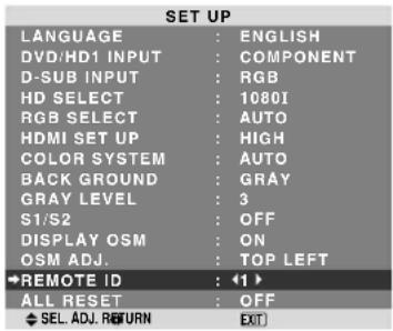
text_image
SET UP LANGUAGE : ENGLISH DVD/HD1 INPUT : COMPONENT D-SUB INPUT : RGB HD SELECT : 1080I RGB SELECT : AUTO HDMI SET UP : HIGH COLOR SYSTEM : AUTO BACK GROUND : GRAY GRAY LEVEL : 3 S1/S2 : OFF DISPLAY OSM : ON OSM ADJ. : TOP LEFT REMOTE ID : ◀1 ► ALL_RESET : OFF SEL ADJ RETURN EXT- Press and hold the POWER ON button, and release the button when the indication saying that the code is set is displayed. Or, press and hold the POWER STANDBY button, and release the button when the power is turned off.
Information
■ REMOTE ID setting
ALL: The remote code is not set.
1 to 4: The specified remote code is applied.
Resetting to the default values
Use these operations to restore all the settings (PICTURE, AUDIO, IMAGE ADJUST, SET UP, etc.) to the factory default values.
Refer to page En-18 for items to be reset.
On “ALL RESET” of “SET UP” menu, select “ON”, then press the MENU/ENTER button.
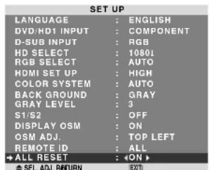
text_image
SET UP LANGUAGE : ENGLISH DVD/HD1 INPUT : COMPONENT D-SUB INPUT : RGB HD SELECT : 10801 RGB SELECT : AUTO HDMI SET UP : HIGH COLOR SYSTEM : AUTO BACK GROUND : GRAY GRAY LEVEL : 3 S1/S2 : OFF DISPLAY OSM : ON OSM ADJ. : TOP LEFT REMOTE ID : ALL +ALL RESET : +ON > SEL. ADJ. RETURN 300
text_image
ALL RESET SETTING NOWWhen the “SETTING NOW” screen disappears, then all the settings are restored to the default values.
Function Settings Menu Setting the menu mode
This allows you to access the complete menu.
Example: Setting "ON"
On “ADVANCED OSM” of “FUNCTION” menu, select “ON”.
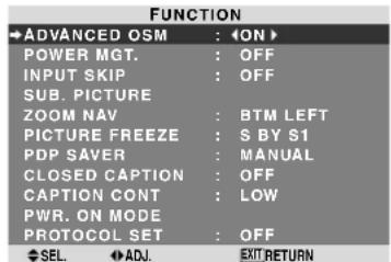
text_image
FUNCTION ADVANCED OSM : ON POWER MGT. : OFF INPUT SKIP : OFF SUB. PICTURE ZOOM NAV : BTM LEFT PICTURE FREEZE : S BY S1 PDP SAVER : MANUAL CLOSED CAPTION : OFF CAPTION CONT : LOW PWR. ON MODE PROTOCOL SET : OFF SEL ADJ EXIT RETURNInformation
■ ADVANCED OSM settings
ON: All of the menu items are available for advanced users.
OFF: Some of the menu items are not available (e.g.FUNCTION).
Setting the power management for computer images
This energy-saving (power management) function automatically reduces the monitor's power consumption if no operation is performed for a certain amount of time.
Example: Turning the power management function on Set "ADVANCED OSM" to "ON" in the FUNCTION menu. On "POWER MGT." of "FUNCTION" menu, select "ON".
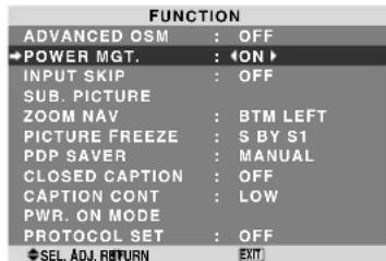
text_image
FUNCTION ADVANCED OSM : OFF POWER MGT. : ON INPUT SKIP : OFF SUB. PICTURE ZOOM NAV : BTM LEFT PICTURE FREEZE : S BY S1 PDP SAVER : MANUAL CLOSED CAPTION : OFF CAPTION CONT : LOW PWR. ON MODE PROTOCOL SET : OFF SEL. ADJ. RETURN EXITInformation
■ Power management function
* The power management function automatically reduces the monitor's power consumption if the computer's keyboard or mouse is not operated for a certain amount of time. This function can be used when using the monitor with a computer.
* If the computer's power is not turned on or if the computer and selector tuner are not properly connected, the system is set to the off state.
* For instructions on using the computer's power management function, refer to the computer's operating instructions.
■ Power management settings
ON: In this mode the power management function is turned on.
OFF: In this mode the power management function is turned off.
■ Power management function and ON/STANDBY indicator
The ON/STANDBY indicator indicates the status of the power management function. See En-28 for indicator status and description.
ON/STANDBY indicator
| Power management mode | ON/ STANDBY Indicator | Power management operating status | Description | Turning the picture back on |
| On | Green | Not activated. | Horizontal and vertical synchronizing signals are present from the computer. | Picture already on. |
| Off | Red | Activated. | Horizontal and/or vertical synchronizing signals are not sent from the computer. | Operate the keyboard or mouse. The picture reappears. |
Setting the Input Skip
When this is ON, signals which are not present will be skipped over and only pictures whose signals are being transmitted will be displayed.
This setting is valid only for the INPUT/EXIT button on the unit.
Example: Set to "ON"
Set "ADVANCED OSM" to "ON" in the FUNCTION menu. On "INPUT SKIP" of "FUNCTION" menu, select "ON".
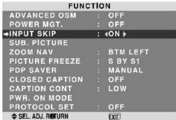
text_image
FUNCTION ADVANCED OSM : OFF POWER MGT. : OFF ←INPUT SKIP :Information
■ INPUT SKIP settings
OFF: Regardless of the presence of the signal, scan and display all signals.
ON: If no input signal is present, skip that signal.
* "SETTING NOW" will appear during the input search.
Removing the sub screen area when there is no input signal detected for the sub screen
This function automatically removes the black frame of the sub screen when there is no sub screen input signal. This feature is available only when the picuture-in-picuture mode is selected.
Example: Setting "DISPLAY" to "FADE"
Set "ADVANCED OSM" to "ON" in the FUNCTION menu.
On "SUB. PICTURE" of "FUNCTION" menu, press the MENU/ENTER button.
The "SUB. PICTURE" screen appears.
Adjust the items.
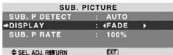
text_image
SUB. PICTURE SUB. P DETECT : AUTO DISPLAY : FADE SUB. P RATE : 100% SEL. ADJ. RETURN EXTInformation
SUB. PICTURE Function
* Loss of the input signal means a condition in which the video signal and the sync signal are not present.
* Under conditions in which the sub screen has disappeared, the ZOOM NAV and PICTURE FREEZE functions will not work. The WIDE button will not function either.
■ SUB. P DETECT setting
AUTO: The black frame disappears 3 seconds after the input signal is lost.
OFF: Turns off the SUB. PICTURE function.
■ DISPLAY setting
NORMAL: The sub screen is displayed consistently.
FADE: The sub screen fades in.
SUB. P RATE setting
Set the transparency of the sub screen.
Displaying the entire image during DIGITAL ZOOM operations
Use this function to display the entire image within the sub screen together with an enlarged image on the main screen.
Example: Setting "ZOOM NAV" to "S BY S"
Set "ADVANCED OSM" to "ON" in the FUNCTION menu. On "ZOOM NAV" of "FUNCTION" menu, select "S BY S".
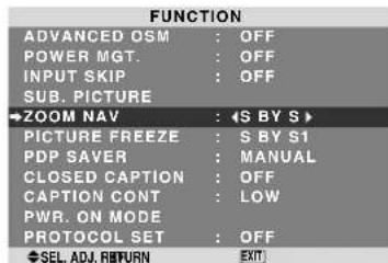
text_image
FUNCTION ADVANCED OSM : OFF POWER MGT. : OFF INPUT SKIP : OFF SUB. PICTURE →ZOOM NAV :Information
■ ZOOM NAV Function
* This feature does not function during multi screen mode.
* This feature does not function while PICTURE FREEZE is operating.
* Providing a 2-screen display will cancel this function.
■ ZOOM NAV settings
OFF: Will not show the entire image on the sub screen. S BY S: Will show the entire image on the sub screen of side-by-side mode.
BTM LEFT\~TOP LEFT: Will show the entire image on the sub screen of picture-in-picture mode.
Side-by-Side Picture-in-Picture
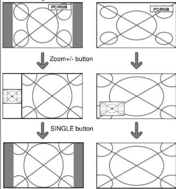
flowchart
graph TD
    A["PC/RGB"] --> B["Zoom+/- button"]
    C["PC/RGB"] --> D["SINGLE button"]
    B --> E["Grid Pattern with Cross-Section"]
    D --> F["Grid Pattern with Cross-Section"]
    E --> G["Final Grid Pattern with Cross-Section"]
    F --> H["Final Grid Pattern with Cross-Section"]
Displaying still images in the sub screen
This feature enables display in the sub screen of still images captured by pressing the ACTIVE SELECT button.
Example: Setting "PICTURE FREEZE" to "BTM En-28 LEFT"
Set "ADVANCED OSM" to "ON" in the FUNCTION menu. On "PICTURE FREEZE" of "FUNCTION" menu, select "BTM LEFT".
| FUNCTION | |
| ADVANCED OSM | : OFF |
| POWER MGT. | : OFF |
| INPUT SKIP | : OFF |
| SUB. PICTURE | |
| ZOOM NAV | : BTM LEFT |
| ●PICTURE FREEZE | : ●BTM LEFT ▶ |
| PDP SAVER | : MANUAL |
| CLOSED CAPTION | : OFF |
| CAPTION CONT | : LOW |
| PWR. ON MODE | |
| PROTOCOL SET | : OFF |
| SEL. ADJ. RETURN | EXIT |
Information
■ PICTURE FREEZE Function
* This feature does not function during multi screen mode.
* Digital zoom is not available while this function is operating.
* A further press of the ACTIVE SELECT button while this function is operating will cancel this function.
* Providing a 2-screen display will cancel this function.
■ PICTURE FREEZE settings
OFF: Will not show the still image.
S BY S1, 2: The still images captured by pressing the ACTIVE SELECT button will be shown on the sub screen of side-by-side mode.
BTM LEFT\~TOP LEFT: The still images captured by pressing the ACTIVE SELECT button will be shown on the sub screen of picture-in-picture mode.
Side-by-Side Picture-in-Picture
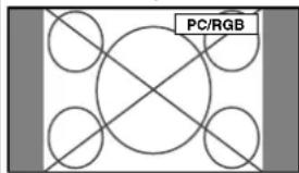
natural_image
Pure electrical circuit lines without any symbolsACTIVE SELECT button
S BY S1
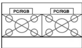
text_image
PC/RGB PC/RGBor
S BY S2
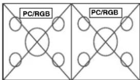
text_image
PC/RGB PC/RGB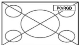
text_image
PC/RGBACTIVE SELECT button
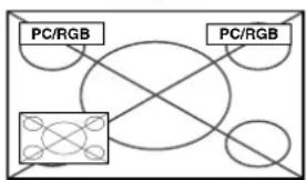
flowchart
graph TD
    A["Central Device"] --> B["PC/RGB"]
    A --> C["PC/RGB"]
    A --> D["PC/RGB"]
    A --> E["PC/RGB"]
Reducing image retention
The brightness of the screen, the position of the picture, positive/negative mode and screen wiper are adjusted to reduce image retention.
Set “ADVANCED OSM” to “ON” in the FUNCTION menu. On “PDP SAVER” of “FUNCTION” menu, select “MANUAL”, then press the MENU/ENTER button.
The "PDP SAVER" screen appears.
| PEAK BRIGHT : 100% | |
| ORBITER | AUTO1 |
| INVERSE/WHITE | OFF |
| SCREEN WIPER | OFF |
| SOFT FOCUS | OFF |
| OSM ORBITER | ON |
| OSM CONTRAST | LOW |
Information
■ When set to AUTO
Set automatically, as described below.
PEAK BRIGHT: 100%
ORBITER: AUTO1 or AUTO2
INVERSE/WHITE: OFF
SCREEN WIPER: OFF
SOFT FOCUS: OFF
OSM ORBITER: ON
OSM CONTRAST: LOW
PEAK BRIGHT
Use this to activate the brightness limiter.
Example: Setting "PEAK BRIGHT" to "75%"
On "PEAK BRIGHT" of "PDP SAVER" menu, select "75%".
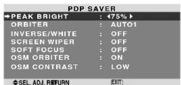
text_image
PDP SAVER PEAK BRIGHT : 75% ORBITER : AUTO1 INVERSE/WHITE : OFF SCREEN WIPER : OFF SOFT FOCUS : OFF OSM ORBITER : ON OSM CONTRAST : LOW SEL. ADJ. RETURN EXITInformation
■ PEAK BRIGHT settings
100%: The brightness of the screen is adjusted automatically to suit the picture quality.
75%, 50%, 25%: Sets maximum brightness.
The brightness level decreases in the order of 75%, 50%, 25%. 25% provides minimum brightness.
* These values are approximate.
ORBITER
Use this to set the picture shift.
Example: Setting "ORBITER" to "AUTO2"
On "ORBITER" of "PDP SAVER" menu, select "AUTO2".
| PDP SAVER | |
| PEAK BRIGHT | : 100% |
| ←ORBITER | : AUTO2 |
| INVERSE/WHITE | : OFF |
| SCREEN WIPER | : OFF |
| SOFT FOCUS | : OFF |
| OSM ORBITER | : ON |
| OSM CONTRAST | : LOW |
| SEL. | ADJ. EXIT RETURN |
Information
■ ORBITER settings
OFF: Orbiter mode does not function.
This is the default setting when PC/RGB is input.
AUTO1: The picture moves around the screen intermittently, making the picture smaller. This is the default setting when a Video or a DVD/HD signal is input. Set to "OFF" when these signals are not used.
AUTO2: The picture moves around the screen
intermittently, making the picture bigger.
* When a Video or a DVD/HD signal is input, the AUTO1 and 2 functions will affect only the moving picture and will not make the screen smaller or bigger.
INVERSE/WHITE
Use this to set the inverse mode or to display a white screen.
Example: Setting "INVERSE/WHITE" to "WHITE"
On “INVERSE/WHITE” of “PDP SAVER” menu, select “WHITE”.

text_image
PDP SAVER PEAK BRIGHT : 100% ORBITER : AUTO1 INVERSE/WHITE : WHITE SCREEN WIPER : OFF SOFT FOCUS : OFF OSM ORBITER : ON OSM CONTRAST : LOW SEL. ADJ. RETURN EXTInformation
■ INVERSE/WHITE Settings
OFF: Inverse/white mode does not function.
INVERSE: The picture is displayed alternately between positive image and negative image.
WHITE: The entire screen turns white.
SCREEN WIPER
When this is set to ON, a white vertical bar moves repeatedly from the left and of the screen to the right end at a constant speed.
Example: Setting "SCREEN WIPER" to "ON"
On “SCREEN WIPER” of “PDP SAVER” menu, select “ON”.
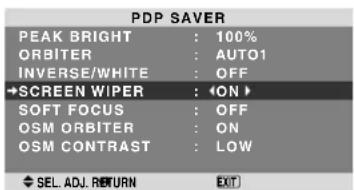
text_image
PDP SAVER PEAK BRIGHT : 100% ORBITER : AUTO1 INVERSE/WHITE : OFF →SCREEN WIPER : ◀ON ► SOFT FOCUS : OFF OSM ORBITER : ON OSM CONTRAST : LOW SEL. ADJ. RETURN EXITInformation
■ SCREEN WIPER
ON: The white vertical bar appears.
OFF: Screen wiper mode does not function.
SOFT FOCUS
Reduces edges and softens the image.
Example: Setting "SOFT FOCUS" to "LEVEL2"
On “SOFT FOCUS” of “PDP SAVER” menu, select “LEVEL2”.
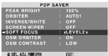
text_image
PDP SAVER PEAK BRIGHT : 100% ORBITER : AUTO1 INVERSE/WHITE : OFF SCREEN WIPER : OFF SOFT FOCUS : LEVEL2 OSM ORBITER : ON OSM CONTRAST : LOW SEL. ADJ. RETURN EXITInformation
■ SOFT FOCUS settings
OFF: Turns the SOFT FOCUS function off.
LEVEL1, 2, 3, 4: Activates the SOFT FOCUS setting.
The higher numbers create a softer image.
“SHARPNESS” can not be adjusted on the “PICTURE” menu.
OSM ORBITER
Use this to set OSM menu shift.
Example: Setting "OSM ORBITER" to "OFF"
On “OSM ORBITER” of “PDP SAVER” menu, select “OFF”.
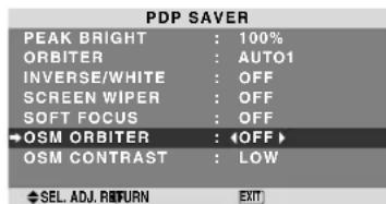
text_image
PDP SAVER PEAK BRIGHT : 100% ORBITER : AUTO1 INVERSE/WHITE : OFF SCREEN WIPER : OFF SOFT FOCUS : OFF OSM ORBITER : OFF OSM CONTRAST : LOW SEL. ADJ. RETURN EXITInformation
■ OSM ORBITER settings
ON: The position of the menu will be shifted by eight dots each time OSM is displayed.
OFF: OSM will be displayed at the same position.
OSM CONTRAST
Use this to reduce the brightness of OSM menu.
Example: Setting "OSM CONTRAST" to "NORMAL"
On “OSM CONTRAST” of “PDP SAVER” menu, select “NORMAL”.
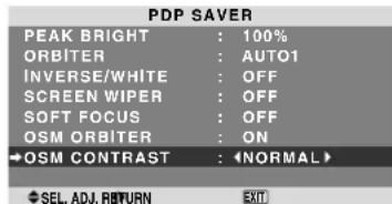
text_image
PDP SAVER PEAK BRIGHT : 100% ORBITER : AUTO1 INVERSE/WHITE : OFF SCREEN WIPER : OFF SOFT FOCUS : OFF OSM ORBITER : ON OSM CONTRAST : NORMAL SEL. ADJ. RETURN EXITInformation
■ OSM CONTRAST settings
NORMAL: OSM brightness is set to normal.
LOW: OSM brightness is set to lower.
Setting Closed Caption
This function sets several closed caption modes that allows text to be superimposed in the active video.
Example: Setting "CAPTION2"
Set "ADVANCED OSM" to "ON" in the FUNCTION menu. On "CLOSED CAPTION" of "FUNCTION" menu, select "CAPTION2".
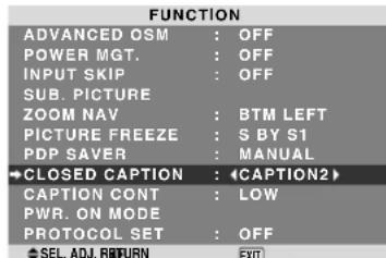
text_image
FUNCTION ADVANCED OSM : OFF POWER MGT. : OFF INPUT SKIP : OFF SUB. PICTURE ZOOM NAV : BTM LEFT PICTURE FREEZE : S BY S1 PDP SAVER : MANUAL →CLOSED CAPTION : ◀CAPTION2 CAPTION CONT : LOW PWR. ON MODE PROTOCOL SET : OFF SEL. ADJ. RETURN EXITInformation
■ CLOSED CAPTION settings
OFF: This exits the closed caption mode.
CAPTION1\~4: Text is superimposed.
TEXT1\~4: Text is displayed in full screen.
A closed caption signal may not be decoded in the following signature;
- when a video tape has been dubbed.
- when the signal reception is weak.
- when the signal reception is nonstandard.
When using closed captioned channel or the text mode, the text screen always appears.
When there is no signal, however, the text screen will not display text characters.
Reducing the brightness of Closed Caption
Use this to reduce the brightness of Closed Caption.
Example: Setting "NORMAL"
Set "ADVANCED OSM" to "ON" in the FUNCTION menu.
On “CAPTION CONT” of “FUNCTION” menu, select “NORMAL”.
| FUNCTION | |
| ADVANCED OSM | : OFF |
| POWER MGT. | : OFF |
| INPUT SKIP | : OFF |
| SUB. PICTURE | |
| ZOOM NAV | : BTM LEFT |
| PICTURE FREEZE | : S BY S1 |
| PDP SAVER | : MANUAL |
| CLOSED CAPTION | : OFF |
| CAPTION CONT | : NORMAL |
| PWR. ON MODE | |
| PROTOCOL SET | : OFF |
| SEL. ADJ. RETURN | EXIT |
Information
■ CAPTION CONT settings
NORMAL: Closed Caption brightness is set to normal.
LOW: Closed Caption brightness is set to lower.
Setting the power on mode
This function sets the input mode and the sound volume at the time the power is switched on.
Example: Setting the input mode to "VIDEO2"
Set "ADVANCED OSM" to "ON" in the FUNCTION menu.
On “FUNCTION” menu, select “PWR.ON MODE”, then press the MENU/ENTER button.
The "PWR.ON MODE" screen appears.
On “INPUT” of “PWR.ON MODE” menu, select “VIDEO2”.
The available inputs depend on the setting of input.
| PWR. ON MODE | ||
| →INPUT | : | <VIDEO2> |
| VOLUME | : | 22 |
| SEL. | ADJ. | EXIT RETURN |
Information
■ INPUT settings
LAST: Last mode (the input that was last selected at the time the power was switched off).
VIDEO1, 2: VIDEO input mode.
DVD/HD1\~4: DVD/HD input mode.
PC/RGB: PC/RGB input mode.
MULTI: Multi screen mode.
■ To set MULTI INPUT
- Set the INPUT button to "MULTI", then press the MENU/ENTER button.
The “MULTI SCREEN SETTING” will appear on the screen.
- Use the ▲ and ▼ buttons to select “MULTI MODE”, then use the ◀ and ▶ buttons to choose from “SIDE BY SIDE1\~3” and “PICTURE IN PICTURE (BOTTOM LEFT\~TOP LEFT)”.
- Use the ▲ and ▼ buttons to select “MAIN”/“SUB” and “LEFT”/“RIGHT”, then use the ◀ and ▶ buttons to choose from “VIDEO1\~2”, “DVD/HD1\~4” and “PC/RGB”.
PICTURE IN PICTURE SIDE BY SIDE
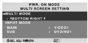
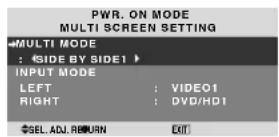
VOLUME settings
LAST: Last mode (the volume that was last selected at the time the power was switched off).
0 to 42: The level of sound volume.
Setting the Protocol set
Use this setting when connecting a device which uses special protocol for RS-232C communication.
Example: Setting "ON"
Set “ADVANCED OSM” to “ON” in the FUNCTION menu. On “PROTOCOL SET” of “FUNCTION” menu, select “ON”.
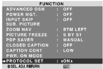
text_image
FUNCTION ADVANCED OSM : OFF POWER MGT. : OFF INPUT SKIP : OFF SUB. PICTURE ZOOM NAV : BTM LEFT PICTURE FREEZE : S BY S1 PDP SAVER : MANUAL CLOSED CAPTION : OFF CAPTION CONT : LOW PWR. ON MODE →PROTOCOL SET : ←ON> SEL. ADJ. RETURN EXITInformation
■ PROTOCOL SET settings
ON: When special protocol is used.
OFF: When NEC protocol is used (normal).
* Consult your dealer for details of protocol.
Signal Information Menu
Checking the frequencies, polarities of input signals, and resolution
Use this function to check the frequencies and polarities of the signals currently being input from a computer, etc. On "MAIN MENU", select "SIGNAL INFO.", then press the MENU/ENTER button.
The "SIGNAL INFORMATION" is displayed.
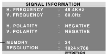
text_image
SIGNAL INFORMATION H. FREQUENCY : 48.4KHz V. FREQUENCY : 60.0Hz H. POLARITY : NEGATIVE V. POLARITY : NEGATIVE — MEMORY : 24 RESOLUTION : 1024×768 EXIT RETURNPC: MEMORY will be displayed.
Others: MODE will be displayed.
External Control
Pin Assignments
Application
These specifications cover the communications control of the plasma monitor by external equipment.
Connections
Connections are made as described below.
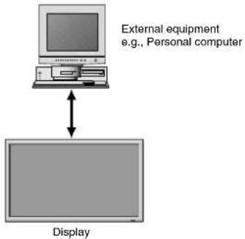
text_image
External equipment e.g., Personal computer DisplayConnector on the plasma monitor side: EXTERNAL CONTROL connector.
Use a crossed (reverse) cable.
Type of connector: D-Sub 9-pin male
| Pin No. | Pin Name | Pin No. | Pin Name |
| 1 | No Connection | 6 | DSR (DCE side ready) |
| 2 | RXD (Receive data) | 7 | RTS (Ready to send) |
| 3 | TXD (Transmit data) | 8 | CTS (Clear to send) |
| 4 | DTR (DTE side ready) | 9 | No connection |
| 5 | GND |
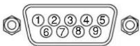
Communication Parameters
(1) Communication system Asynchronous
(2) Interface RS-232C
(3) Baud rate 9600 bps
(4) Data length 8 bits
(5) Parity Odd
(6) Stop bit 1 bit
(7) Communication code Hex
External Control Codes (Reference)
FUNCTION CODE DATA
Power ON 9FH 80H 60H 4FH 00H CDH
OFF 9FH 80H 60H 4FH 00H CEH
| Input Switch Video1 (RCA) DFH 80H 60H 47H 01H 01H 06H | ||
| Video2 (S-Video) | DFH 80H 60H 47H 01H 02H 09H | |
| DVD/HD1 (RCA) | DFH 80H 60H 47H 01H 05H 0CH | |
| DVD/HD2 (RCA) | DFH 80H 60H 47H 01H 06H 0DH | |
| DVD/HD3 (HDMI) | DFH 80H 60H 47H 01H 0EH 15H | |
| PC/RGB (mini D-sub 15-pin) | DFH 80H 60H 47H 01H 07H 0EH | |
| DVD/HD4 (HDMI) | DFH 80H 60H 47H 01H 1AH 21H | |
| Audio Mute | ON | 9FH 80H 60H 3EH 00H BDH |
| OFF | 9FH 80H 60H 3FH 0CH BEH | |
| Picture Mode | NORMAL | DFH 80H 60H 0AH 01H 01H CBH |
| THEATER 1 | DFH 80H 60H 0AH 01H 02H CCH | |
| THEATER 2 | DFH 80H 60H 0AH 01H 03H CDH | |
| DEFAULT | DFH 80H 60H 0AH 01H 04H CEH | |
| BRIGHT | DFH 80H 60H 0AH 01H 05H CFH | |
| Screen Mode | STADIUM | DFH 80H 60H 51H 01H 02H 13H |
| ZOOM | DFH 80H 60H 51H 01H 03H 14H | |
| NORMAL | DFH 80H 60H 51H 01H 04H 15H | |
| ANAMORPHIC | DFH 80H 60H 51H 01H 05H 16H | |
| UNDERSCAN | DFH 80H 60H 51H 01H 08H 19H | |
| 14 : 9 | DFH 80H 60H 51H 01H 09H 1AH | |
| 2.35 : 1 | DFH 80H 60H 51H 01H 0AH 1BH | |
| Auto Picture | ON | DFH 80H 60H 7FH 03H 03H 09H 00H 4DH |
| OFF | DFH 80H 60H 7FH 03H 03H 09H 01H 4EH | |
| Cinema Mode | ON | DFH 80H 60H C1H 01H 01H 82H |
| OFF | DFH 80H 60H C1H 01H 02H 83H | |
Note: Contact your local dealer for a full list of the External Control Codes if needed.
| Pin No. | Signal (Analog) |
| 1 | Red |
| 2 | Green or sync-on-green |
| 3 | Blue |
| 4 | No connection |
| 5 | Ground |
| 6 | Red ground |
| 7 | Green ground |
| 8 | Blue ground |
| 9 | No connection |
| 10 | Sync signal ground |
| 11 | No connection |
| 12 | Bi-directional DATA (SDA) |
| 13 | Horizontal sync or Composite sync |
| 14 | Vertical sync |
| 15 | Data clock |
1/8 Stereo Mini Jack (not supplied) for REMOTE IN/OUT
Plasma monitor REMOTE IN
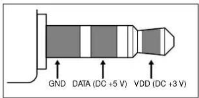
text_image
GND DATA (DC +5 V) VDD (DC +3 V)Plasma monitor REMOTE OUT
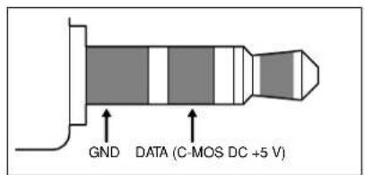
text_image
GND DATA (C-MOS DC +5 V)Following is the connection example of STB (Set-top Box) using the REMOTE IN/OUT connectors of the plasma monitor. Consult your dealer about the actual connection and operation.
* Connection Example
• STB has the REMOTE IN connector.
- The pin assignment of the REMOTE IN connector of STB is same as that of 1/8 stereo mini cable connected to the REMOTE OUT connector (En-32).
- The transmit frequency of the remote control of STB is 37.9 kHz (Typical).
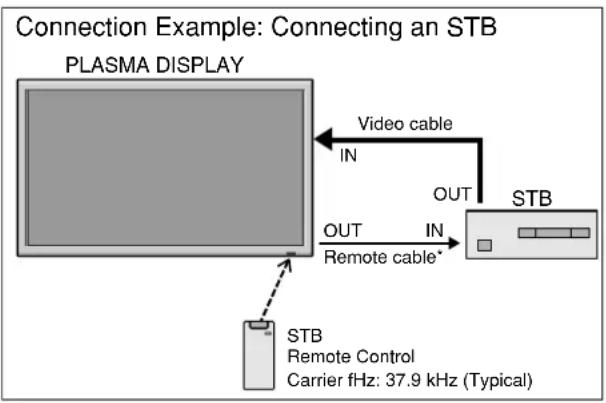
flowchart
graph TD
    A["PLASMA DISPLAY"] -->|Video cable IN| B["STB"]
    A -->|OUT IN| C["Remote cable*"]
    B --> D["STB Remote Control Carrier fHz: 37.9 kHz (Typical)"]
* The 1/8 Stereo Mini cable must be purchased separately.
If the picture quality is poor or there is some other problem, check the adjustments, operations, etc., before requesting service.
| Symptom | Checks | Remedy |
| The unit emits a crackling sound. | Are the image and sound normal? | If there are no abnormalities in the image and sound, the noise is caused by the cabinet reacting to changes in temperature. This will not affect performance. |
| Picture is disturbed.Sound is noisy.Remote control operates erroneously. | Is a connected component set directly in front or at the side of the display? | Leave some space between the display and the connected components. |
| The remote control does not work. | Are the remote control's batteries worn out? | Replace both batteries with new ones. |
| Monitor's power does not turn on when the remote control's power button is pressed. | Is the monitor's power cord plugged into a power outlet? | Plug the monitor's power cord into a power outlet. |
| Are all the monitor's indicators off? | Press the power button on the monitor to turn on the power. | |
| Are the remote control's batteries worn out? | Replace both batteries with new ones. | |
| Monitor does not operate when the remote control's buttons are pressed. | Is the remote control pointed at the monitor, or is there an obstacle between the remote control and the monitor? | Point the remote control at the monitor's remote control sensor when pressing buttons, or remove the obstacle. |
| Is direct sunlight or strong artificial light shining on the monitor's remote control sensor? | Eliminate the light by closing curtains, pointing the light in a different direction, etc. | |
| Are the remote control's batteries worn out? | Replace both batteries with new ones. | |
| No sound or picture is produced. | Is the monitor's power cord plugged into a power outlet? | Plug the monitor's power cord into a power outlet. |
| Picture appears but no sound is produced. | Is the volume set at the minimum? | Increase the volume. |
| Is the mute mode set?Are the speakers properly connected? | Press the remote control's MUTE button.Connect the speakers properly. | |
| Is AUDIO INPUT set correctly? | Set AUDIO INPUT on the AUDIO menu correctly. | |
| Poor picture with VIDEO signal input. | Improper control setting.Local interference.Cable interconnections.Input impedance is not correct level. | Adjust picture control as needed.Try another location for the monitor.Be sure all connections are secure. |
| Poor picture with RGB signal input. | Improper control setting.Incorrect 15 PIN connector pin connections. | Adjust picture controls as needed.Check pin assignments and connections. |
| Tint is poor or colors are weak. | Are the tint and colors properly adjusted? | Adjust the tint and color (under PICTURE). |
| Nothing appears on screen. | Is the computer's power turned on? | Turn on the computer's power. |
| Is a source connected? | Connect source to the monitor. | |
| Is the power management function in the standby or off mode? | Operate the computer (move the mouse, etc.). | |
| Part of picture is cut off or picture is not centered. | Is the position adjustment appropriate? | Adjust the IMAGE ADJUST properly. |
| Image is too large or too small. | Is the screen size adjustment appropriate? | Press the WIDE button on the remote control and adjust properly. |
| Picture is unstable. | Is the computer's resolution setting appropriate? | Set to the proper resolution. |
| ON/STANDBY indicator is lighted in red. | Horizontal and / or vertical sync signal is not present when the Intelligent Power Manager control is on. | Check the input signal. |
| ON/STANDBY indicator is blinking in red. | The temperature inside the main unit has become too high and has activated the protector. | Promptly switch off the power of the main unit and wait until the internal temperature drops. See*1. |
| ON/STANDBY indicator is blinking in green and red, or green. | —— | Prompty switch off the power of the main unit. See *2. |
*1 Overheat protector
If the monitor becomes too hot, the overheat protector will be activated and the monitor will be turned off. If this happens, turn off the power to the monitor and unplug the power cord. If the room where the monitor is installed is particularly hot, move the monitor to a cooler location and wait for the monitor to cool for 60 minutes. If the problem persists, contact your dealer.
*2 In the following case, power off the monitor immediately and contact your dealer or authorized Service Center.
The monitor turns off 5 seconds after powering on and then the ON/STANDBY indicator blinks. It indicates that the power supply circuit, plasma display panel, temperature sensor, or one or more fans have been damaged.
NEC Corporation of America warrants this product to be free from defects in material and workmanship under the following terms and, subject to the conditions set forth below, agrees to repair or replace (at NEC Corporation of America' sole option) any part of the enclosed unit which proves defective. Replacement parts or products may be new or refurbished and will meet specifications of the original parts or products.
HOW LONG IS THE WARRANTY?
Parts and Labor: Parts and Labor (Excluding the PDP) are warranted for (3) three years from the date of the first customer purchase.
PDP (Plasma Display Panel): The PDP is warranted for (1) one year from the date of the first customer purchase.
WHO IS PROTECTED?
This warranty may be enforced only by the first purchaser.
WHAT IS COVERED AND WHAT IS NOT COVERED
Except as specified below, this warranty covers all defects in material or workmanship in this product. The following are not covered by the warranty:
- Any product which is not distributed in the U.S.A. or Canada by NEC Corporation of America or which is not purchased in the U.S.A. or Canada from an authorized NEC Corporation of America dealer.
- Any product of which the serial number has been defaced, modified or removed.
- Damage, deterioration or malfunction resulting from:
a. Accident, misuse, abuse, neglect, fire, water, lightning or other acts of nature, unauthorized product modification, or failure to follow instructions supplied with the product.
b. Repair or attempted repair by anyone not authorized by NEC Corporation of America.
c. Any shipment of the product (claims must be presented to the carrier).
d. Removal or installation of the product.
e. Any other cause which does not relate to a product defect.
f. Burns or residual images upon the phosphor of the panel.
-
Cartons, carrying cases, batteries, external cabinets, magnetic tapes, or any accessories used in connection with the product.
-
Service outside of the U.S.A. and Canada.
WHAT WE WILL PAY FOR AND WHAT WE WILL NOT PAY FOR
We will pay labor and material expenses for covered items, but we will not pay for the following:
- Removal or installation charges.
-
Costs of initial technical adjustments (set-up), including adjustment of user controls. These costs are the responsibility of the NEC Corporation of America dealer from whom the product was purchased.
-
Shipping charges,
HOW YOU CAN GET WARRANTY SERVICE
- To obtain service on your product, consult the dealer from whom you purchased the product.
- Whenever warranty service is required, the original dated invoice (or a copy) must be presented as proof of warranty coverage. Please also include in any mailing your name, address and a description of the problem(s).
- For the name of the nearest NEC Corporation of America authorized service center, call NEC Corporation of America at 800-836-0655.
LIMITATIONS OF LIABILITY
Except for the obligations specifically set forth in this warranty statement, we will not be liable for any direct, indirect, special, incidental, consequential, or other types of damages, whether based on contract, tort, or any other legal theory, whether or not we have been advised of the possibility of such damages. This warranty is in lieu of all other warranties expressed or implied, including, but not limited to, the implied warranties of merchantability or fitness for a particular purpose.
EXCLUSION OF DAMAGES
NEC Corporation of America' liability for any defective product is limited to the repair or replacement of the product at our option. NEC Corporation of America shall not be liable for:
- Damage to other property caused by any defects in this product, damages based upon inconvenience, loss of use of the product, loss of time, commercial loss; or
- Any other damages whether incidental, consequential or otherwise. Some states do not allow limitation on how long an implied warranty lasts and/or do not allow the exclusion or limitation of incidental or consequential damages, so the above limitations and exclusions may not apply to you.
HOW STATE LAW RELATES TO THE WARRANTY
This warranty gives you specific legal rights, and you may also have other rights which vary from state to state.
FOR MORE INFORMATION,
TELEPHONE 800-836-0655
NEC CORPORATION OF AMERICA
1250 N. Arlington Heights Road, Suite 400
Itasca, Illinois 60143-1248
Note: All products returned to NEC Corporation of America for service MUST have prior approval. To get approval, call NEC Corporation of America at 800-836-0655.
Mode d'emploi
RISQUE D'ELECTROCUTION NE PAS OUVRIR

ATTENTION:
POUR EVITER TOUT RISQUE D'ELECTROCUTION, NE PAS OUVRIR LE BOITIER. A L'INTERIEUR, AUCUNE PIECE NE NECESSITE L'INTER-VENTION DE L'UTILISATEUR. EN CAS DE PROBLEME, S'ADRESSER A UN REPARATEUR SPECIALISTE.

natural_image
Diagram of a flat-panel monitor mounted on a base with a wavy surface underneath (no text or symbols)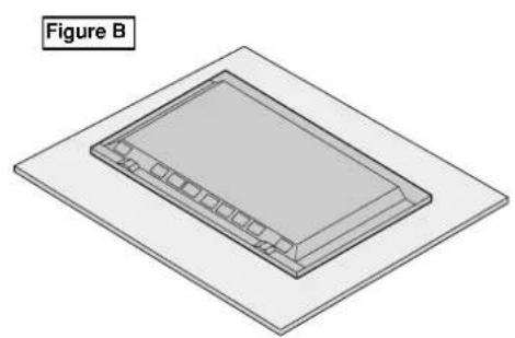
natural_image
Isometric diagram of a rectangular device with internal components, labeled 'Figure B' (no text or symbols on the device itself)natural_image
Technical line drawing of a remote control panel with a black arrow indicating rotation (no text or symbols)natural_image
Technical line drawing of a mechanical device with a black arrow indicating a component (no text or symbols)natural_image
Line drawing of a mechanical component with a triangular clip inserted into a base (no text or symbols)text_image
Approx. 7 m/23 pieds 30° 30°ATTENTION
text_image
L B D A C E F G H I J KA AC IN (ENTREE DU CORDON D'ALIMENTATION ELECTRIQUE CA)
HDMI, the HDMI logo and High-Definition Multimedia Interface are trademarks or registered trademarks of HDMI Licensing LLC.
text_image
L B D A C E F G H I J KA AC IN (ENTREE DU CORDON D'ALIMENTATION ELECTRIQUE CA)
HDMI, the HDMI logo and High-Definition Multimedia Interface are trademarks or registered trademarks of HDMI Licensing LLC.
text_image
L B D A C E F G H I J KA AC IN (ENTREE DU CORDON D'ALIMENTATION ELECTRIQUE CA)
HDMI, the HDMI logo and High-Definition Multimedia Interface are trademarks or registered trademarks of HDMI Licensing LLC.
Télécommande
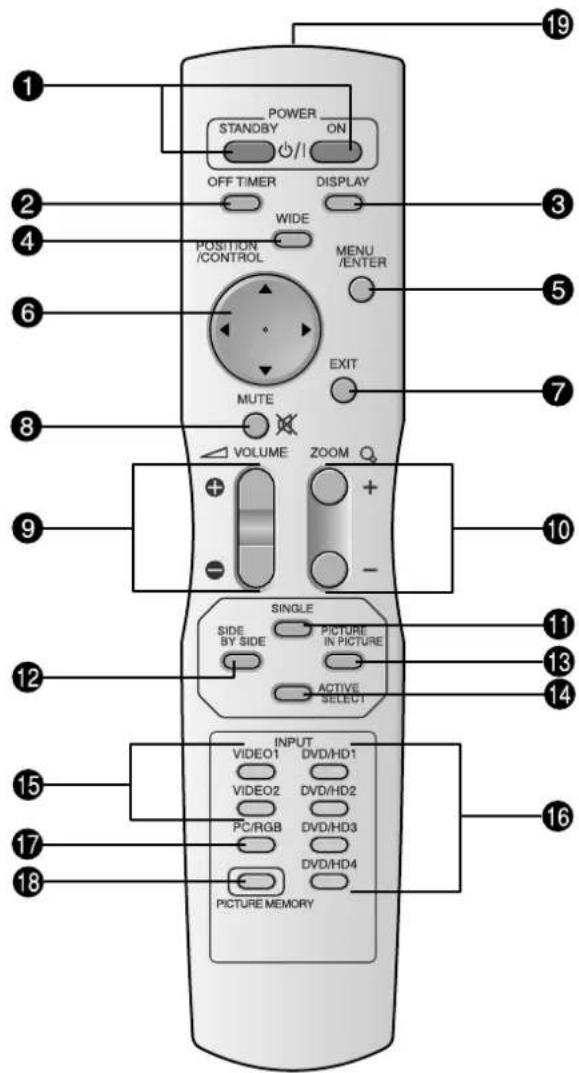
text_image
POWER STANDBY ON OFF TIMER DISPLAY WIDE POSITION /CONTROL MENU /ENTER MUTE EXIT VOLUME ZOOM + + - SINGLE SIDE BY SIDE PICTURE IN PICTURE ACTIVE SELECT INPUT VIDEO1 DVD/HD1 VIDEO2 DVD/HD2 PC/RGB DVD/HD3 DVD/HD4 PICTURE MEMORY 19 3 5 7 10 11 13 14 15 16 17 18⑬ PICTURE IN PICTURE
natural_image
Geometric diagram with four circles arranged in a cross pattern, no text or symbols presentnatural_image
Pure geometric diagram with intersecting circles and diagonal lines inside a rectangle (no text or symbols)natural_image
Geometric diagram with a central circle and surrounding circles, no text or symbols presentnatural_image
Geometric diagram with concentric circles and semicircles, no text or symbols presentnatural_image
Pure geometric diagram with circles and diagonal lines inside a rectangle, no text or symbols presentnatural_image
Geometric diagram with a circle inscribed in a rectangle and two diagonal lines forming an X (no text or symbols)natural_image
Pure geometric diagram of a rectangle with internal circles and diagonal lines, no text or symbols present.Sous-balayage
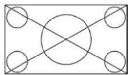
natural_image
Pure geometric diagram with intersecting circles and diagonal lines inside a rectangle (no text or symbols)Sur-balayage
natural_image
Geometric pattern with four circles and diagonal lines forming a cross (no text or symbols)natural_image
Geometric pattern with intersecting circles and diagonal lines forming a cross (no text or symbols)natural_image
Geometric pattern with concentric circles and intersecting lines inside a rectangle (no text or symbols)natural_image
Pure geometric diagram with intersecting circles and diagonal lines inside a rectangle (no text or symbols)Informations
text_image
MODE IMAGE : CINEMA1Informations
■ Mode d'affichage
flowchart
graph TD
    A["PC/RGB"] --> B["bouton Zoom+/-"]
    C["PC/RGB"] --> D["bouton SINGLE"]
    B --> E["Diagram of circles arranged in a grid"]
    D --> F["Diagram of circles arranged in a grid"]
    E --> G["Diagram of circles arranged in a grid"]
    F --> H["Diagram of circles arranged in a grid"]
natural_image
Pure geometric diagram with intersecting circles and diagonal lines, no text or symbols present
Image-dans-Image
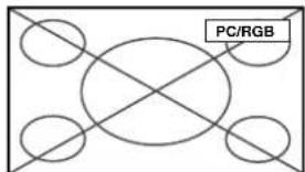
text_image
PC/RGB
CTACT1
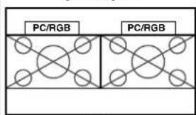
text_image
PC/RGB PC/RGBou
CTACT2
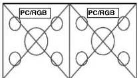
text_image
PC/RGB PC/RGB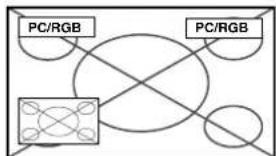
flowchart
graph TD
    A["Central Node"] --> B["PC/RGB"]
    A --> C["PC/RGB"]
    A --> D["PC/RGB"]
    A --> E["PC/RGB"]
INV./FD BLANC: ARRET
SCREEN WIPER: ARRET
FOCUS LEGER: ARRET
POSITION OSM: MARCHE
CONTRASTE OSM: BASSE-
PLE (Peak Luminance Enhancement)
1250 N. Arlington Heights Road, Suite 400
Itasca, Illinois 60143-1248
natural_image
Illustration of a flat-screen monitor with a wavy screen and a base mount, labeled 'Ilustración A' (no other text or symbols)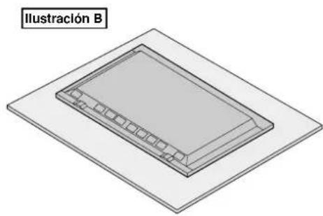
natural_image
3D diagram of a rectangular object with internal grid pattern, labeled 'Ilustración B' (no other text or symbols)natural_image
Technical line drawing of a remote control panel with a black arrow indicating rotation (no text or symbols)natural_image
Technical line drawing of a mechanical component with a handle and mounting holes (no text or symbols)- Instale la tapa.

natural_image
Line drawing of a mechanical component with a handle and mounting holes (no text or symbols)Radio de acción
text_image
Aprox. 7 m/23 pies 30° 30°PRECAUCIÓN
text_image
A B D C E F G H I J KA AC IN
HDMI, the HDMI logo and High-Definition Multimedia Interface are trademarks or registered trademarks of HDMI Licensing LLC.
Vista Posterior/Placa de terminales 50XR6
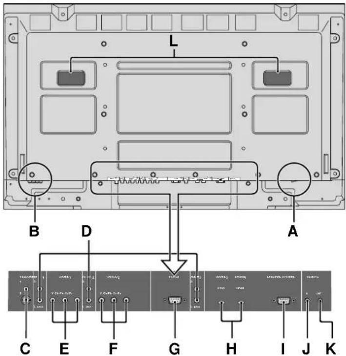
text_image
L B D A C E F G H I J KA AC IN
HDMI, the HDMI logo and High-Definition Multimedia Interface are trademarks or registered trademarks of HDMI Licensing LLC.
Vista Posterior/Placa de terminales 60XR5
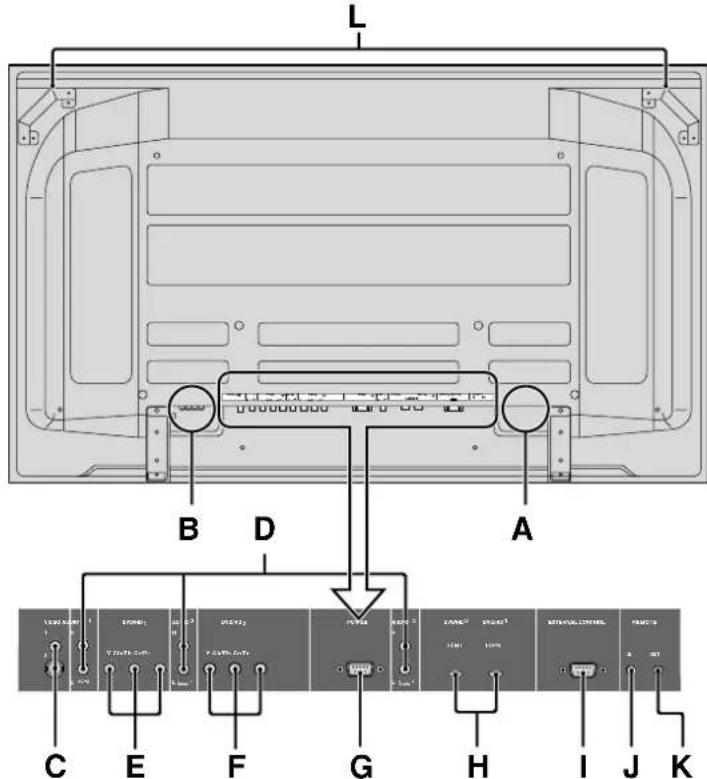
text_image
L B D A C E F G H I J KA AC IN
HDMI, the HDMI logo and High-Definition Multimedia Interface are trademarks or registered trademarks of HDMI Licensing LLC.
Mando a distancia
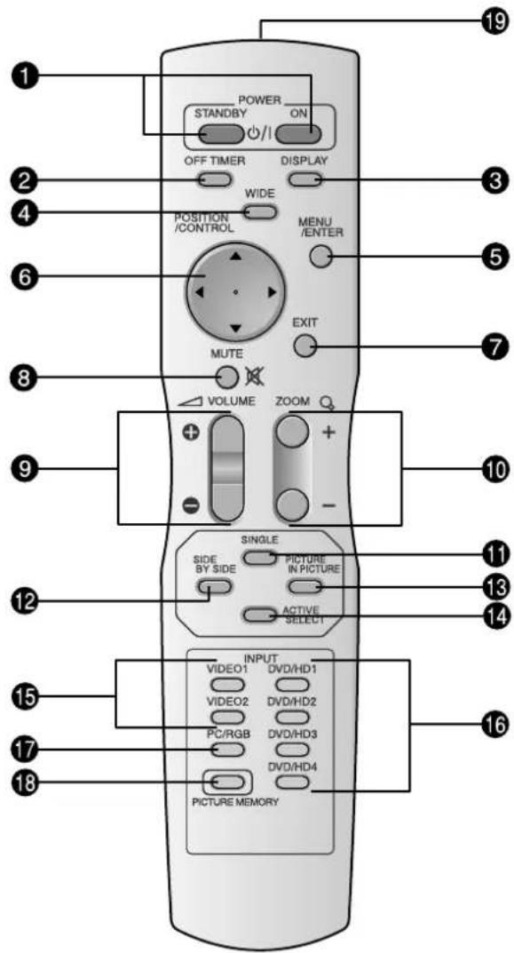
text_image
POWER STANDBY ON OFF TIMER DISPLAY WIDE POSITION /CONTROL MENU /ENTER MUTE EXIT VOLUME ZOOM + + - + - SINGLE SIDE BY SIDE PICTURE IN PICTURE ACTIVE SELECT INPUT VIDEO1 DVD/HD1 VIDEO2 DVD/HD2 PC/RGB DVD/HD3 DVD/HD4 PICTURE MEMORY 19 3 5 7 10 11 13 14 15 16 17 18① POWER ON/STANDBY
⑬ PICTURE IN PICTURE
natural_image
Geometric diagram with four circles arranged in a cross pattern within a rectangle (no text or symbols)natural_image
Geometric diagram with four circles arranged in a cross pattern inside a rectangle (no text or symbols)natural_image
Geometric diagram with intersecting circles and diagonal lines inside a rectangle (no text or symbols)natural_image
Geometric diagram with concentric circles and intersecting lines, no text or symbols presentnatural_image
Pure geometric diagram with circles and diagonal lines inside a rectangle, no text or symbols presentnatural_image
Geometric diagram with a circle and two diagonal lines inside a rectangle (no text or symbols)natural_image
Pure geometric diagram of a rectangle with internal circles and four corner arcs, no text or symbols present.Overscan
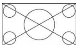
Underscan
natural_image
Geometric pattern with intersecting circles and diagonal lines forming a symmetrical design (no text or symbols)natural_image
Geometric diagram with four circles and diagonal lines inside a rectangle (no text or symbols)natural_image
Geometric diagram with concentric circles and semicircles, no text or symbols presentnatural_image
Pure geometric diagram with intersecting circles and diagonal lines inside a rectangle (no text or symbols)Información
1250 N. Arlington Heights Road, Suite 400
Itasca, Illinois 60143-1248
Vista frontal....Po-7
Vista posterior/Placa de terminais.... Po-8
Controle remoto Po-11
Ajustar as cores ...... Po-22
natural_image
3D diagram of a panel mounted on a base with a wavy pattern underneath, labeled 'Figura A' (no other text or symbols)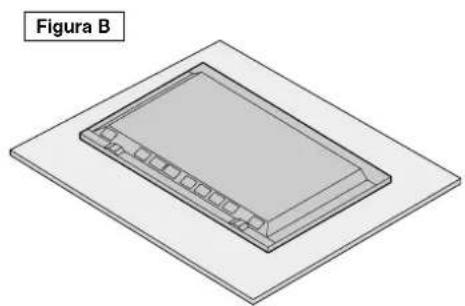
natural_image
Isometric diagram of a rectangular device with internal components, labeled 'Figura B' (no text or symbols on the device itself)natural_image
Technical line drawing of a remote control device with a handle and screw base (no text or symbols)- Volte a colocar a tampa.
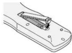
natural_image
Line drawing of a mechanical component with a handle and mounting holes (no text or symbols)Alcance de funcionamento
text_image
Aprox. 7 m 30° 30°CUIDADO
text_image
L B D A C E F G H I J KA AC IN
| EXTERNAL CONTROL (D-Sub)
HDMI, the HDMI logo and High-Definition Multimedia Interface are trademarks or registered trademarks of HDMI Licensing LLC.
Vista posterior/Placa de terminais 50XR6
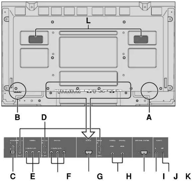
text_image
L B D A C E F G H I J KA AC IN
| EXTERNAL CONTROL (D-Sub)
HDMI, the HDMI logo and High-Definition Multimedia Interface are trademarks or registered trademarks of HDMI Licensing LLC.
Vista posterior/Placa de terminais 60XR5
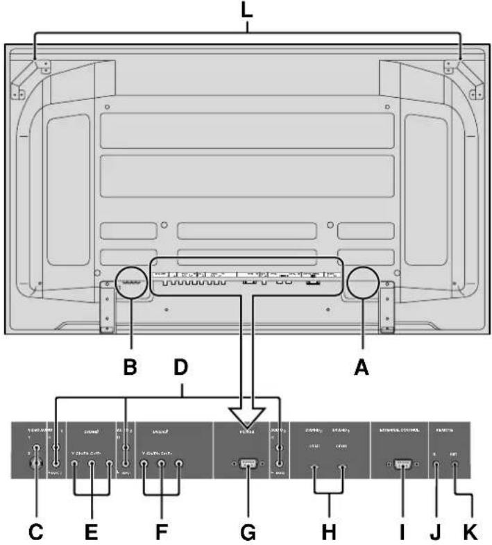
text_image
L B D A C E F G H I J KA AC IN
I EXTERNAL CONTROL (D-Sub)
HDMI, the HDMI logo and High-Definition Multimedia Interface are trademarks or registered trademarks of HDMI Licensing LLC.
Controle remoto

text_image
POWER STANDBY ON OFF TIMER DISPLAY WIDE POSITION /CONTROL MENU /ENTER MUTE EXIT VOLUME ZOOM + + - SINGLE SIDE BY SIDE PICTURE IN PICTURE ACTIVE SELECT INPUT VIDEO1 DVD/HD1 VIDEO2 DVD/HD2 PC/RGB DVD/HD3 DVD/HD4 PICTURE MEMORY① POWER ON/STANDBY
⑬ PICTURE IN PICTURE
natural_image
Geometric diagram with four circles arranged in a cross pattern, no text or symbols presentÉ visualizado o tamanho de écran normal.
natural_image
Geometric diagram with intersecting circles and diagonal lines inside a rectangle (no text or symbols)natural_image
Geometric pattern with intersecting circles and diagonal lines inside a rectangle (no text or symbols)natural_image
Geometric pattern with concentric circles and semicircles, no text or symbols presentnatural_image
Pure geometric diagram with circles and diagonal lines inside a rectangle, no text or symbols presentnatural_image
Geometric diagram with a circle and intersecting lines inside a rectangle (no text or symbols)natural_image
Pure geometric diagram of a rectangle with internal circles and diagonal lines, no text or symbols present.Overscan
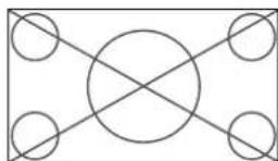
Underscan
natural_image
Geometric pattern with four circles and diagonal lines forming a cross (no text or symbols)natural_image
Geometric diagram with intersecting circles and diagonal lines, no text or symbols presentnatural_image
Geometric pattern with concentric circles and intersecting lines, no text or symbols presentnatural_image
Pure geometric diagram with intersecting circles and diagonal lines inside a rectangle (no text or symbols)Informação
1250 N. Arlington Heights Road, Suite 400
Itasca, Illinois 60143-1248
NEC and the NEC logo are registered trademarks
of NEC Corporation