PA6240 - Receiver Monacor - Free user manual and instructions
Find the device manual for free PA6240 Monacor in PDF.
| Product type | 6-zone PA amplifier-mixer (receiver) |
| Brand | Monacor |
| Model | PA6240 |
| Nominal power (100 V outputs) | 6 × 100 W RMS (max 240 W RMS total) |
| Nominal power (4 Ω output) | 1 × 240 W RMS |
| Max output power | 340 W |
| Distortion rate | < 1 % at 1 kHz |
| MIC/LINE inputs 1-3 | Sensitivity 2.5-300 mV adjustable, impedance 5 kΩ, balanced XLR/6.35 mm jack connectors |
| LINE inputs 4 and 5 | Sensitivity 300 mV, impedance 15 kΩ, unbalanced RCA connectors |
| PAGING IN input | 250 mV, 5 kΩ, balanced |
| Zone outputs | 6 × 100 V (screw terminals) |
| Direct outputs | 1 × 100 V, 1 × 4 Ω |
| PRE OUT and REC outputs | 775 mV (PRE OUT on 6.35 mm jack, REC on RCA) |
| Equalizer | Bass ±10 dB at 100 Hz, treble ±10 dB at 10 kHz |
| Mains power | 230 V / 50 Hz |
| Backup power | 24 V DC / 20 A (terminals) |
| Dimensions (W × H × D) | 482 × 133 × 352 mm (3 rack units) |
| Weight | 17.0 kg |
| Protection | Overload, overheating, short-circuit (LED PROTECT) |
| Cooling | Temperature-controlled variable speed fan |
| Optional accessories | Insert modules (PA-1120DMT, PA-1140RCD, PA-1200C, PA-1200RDSU), desktop microphones (PA-4000PTT, PA-4300PTT, PA-6000RC), surveillance/detection/anti-feedback modules (PA-6FD, PA-6FM, PA-6FR) |
Frequently Asked Questions - PA6240 Monacor
User questions about PA6240 Monacor
0 question about this device. Answer the ones you know or ask your own.
Ask a new question about this device
Download the instructions for your Receiver in PDF format for free! Find your manual PA6240 - Monacor and take your electronic device back in hand. On this page are published all the documents necessary for the use of your device. PA6240 by Monacor.
USER MANUAL PA6240 Monacor
New option for microphone priority starting from serial number ...-03
For all devices whose serial number ends with "-03", the priority of the input channels CH1-CH3 and of the siren can be switched off. To do this, disconnect the device from the power supply and remove the housing cover. Set the switch SW1 in the rear part of the device to the position OFF ( drawing). The signals of the channels CH1 - CH3 and of the siren will then no longer fade out the signals of the channels CH4 - CH5, for example, but they will mix with these signals.
It will, however, still be possible to individually assign a higher priority (3rd priority level) to the channels CH1-CH3 by means of the corresponding switch MIC PRIORITY.
Français
PA Mixing Amplifier for 6 Zones

MONACOR
WWW.MONACOR.COM
PA-6240
PA Mixing Amplifier for 6 Zones
These instructions are intended for installers of PA systems (chapters 4 and 5) and for users without any specific technical knowledge (chapter 6). Please read the instructions carefully prior to operation and keep them for later reference.
All operating elements and connections described can be found on the fold-out page 3.
Contents
1.1 Front panel 10
1.2 Rear panel 10
1.3 Zone paging microphone PA-6000RC 11
1.4 Fault detecting module PA-6FD. 11
1.5 Fault monitoring module PA-6FM 11
1.6 Anti-feedback module PA-6FR 11
1 Operating Elements and Connections 10
2 Safety Notes 11
3 Applications and Accessories 11
4 Installation of Additional Modules 12
4.1 Connection module for PA-6000RC 12
4.1.1 Installation and connection 12
4.1.2 Microphone connection and basic setting. 12
4.2 Fault detection module PA-6FD. 12
4.2.1 Installation and connection 12
4.2.2 Calibration. 12
4.3 Fault monitoring module PA-6FM 12
4.4 Anti-feedback module PA-6FR 12
4.4.1 Installation and connection 12
4.4.2 Operation 13
5 Setting into Operation. 13
5.1 Setting up the amplifier. 13
5.1.1 Rack installation 13
5.2 Adjusting the chime sound and the priority of the insertion module. 13
5.3 Making connections 13
5.3.1 Speakers 13
5.3.2 Microphones 13
5.3.3 Desk microphone PA-4000PTT or PA-4300PTT 13
5.3.4 Units with line output/recorder 13
5.3.5 Inserting an equalizer or another unit 13
5.3.6 Additional amplifier 13
5.3.7 Telephone bell or night bell 14
5.3.8 Telephone switchboard 14
5.3.9 Switch for announcements in all zones 14
5.3.10 Emergency priority relays 14
5.3.11 Switch for switching on and off by remote control 14
5.3.12 Power supply and emergency power supply 14
5.4 Defining the priority of the input signals 14
6 Operation 14
6.1 Adjusting the volume 14
6.2 Activating the PA zones 15
6.3 Chime 15
6.4 Alarm siren 15
6.5 Zone paging microphone PA-6000RC 15
6.6 Desk microphone PA-4000PTT/PA-4300PTT. 15
7 Protective Circuit 15
8 Specifications 15
Layout and connection plan 48
Block diagram. 19
1 Operating Elements and Connections
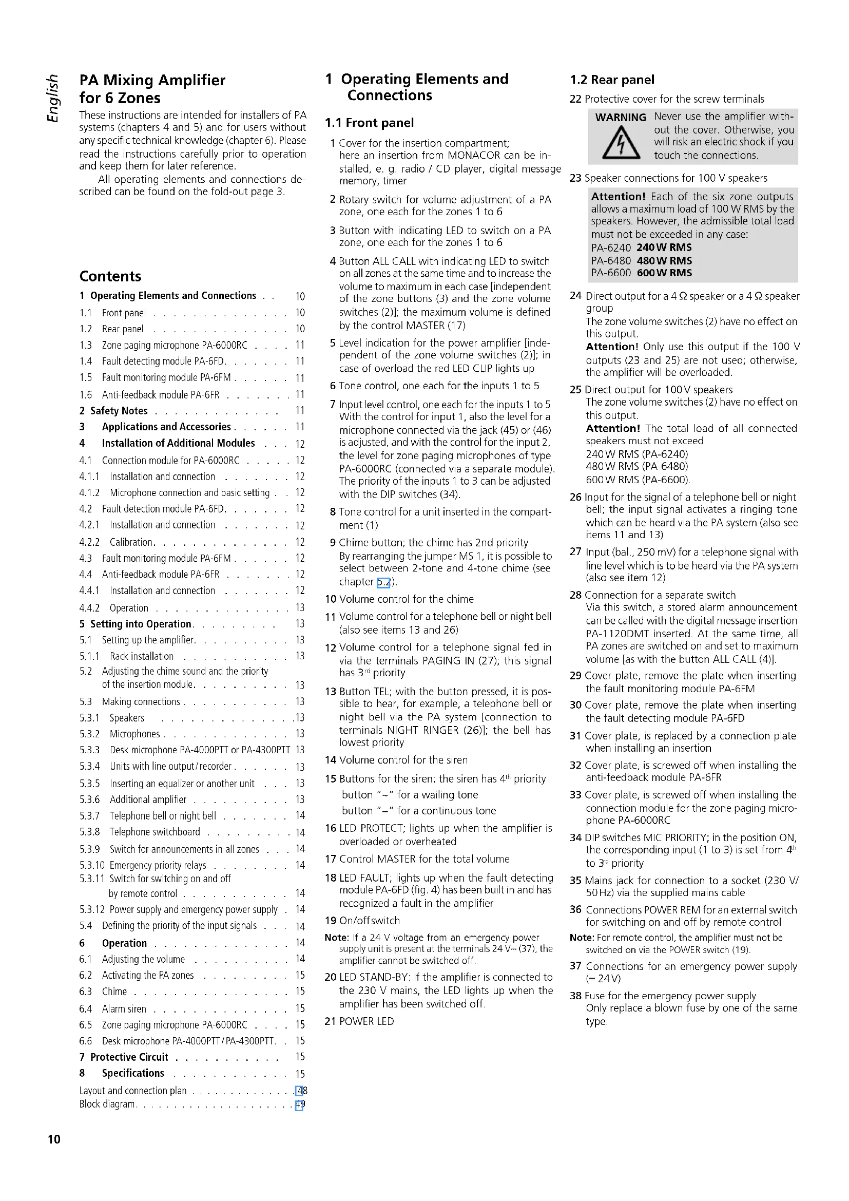
1.1 Front panel
1 Cover for the insertion compartment; here an insertion from MONACOR can be installed, e.g. radio / CD player, digital message memory, timer
2 Rotary switch for volume adjustment of a PA zone, one each for the zones 1 to 6
3 Button with indicating LED to switch on a PA zone, one each for the zones 1 to 6
4 Button ALL CALL with indicating LED to switch on all zones at the same time and to increase the volume to maximum in each case [independent of the zone buttons (3) and the zone volume switches (2)]; the maximum volume is defined by the control MASTER (17)
5 Level indication for the power amplifier [independent of the zone volume switches (2); in case of overload the red LED CLIP lights up
6 Tone control, one each for the inputs 1 to 5
7 Input level control, one each for the inputs 1 to 5 With the control for input 1, also the level for a microphone connected via the jack (45) or (46) is adjusted, and with the control for the input 2, the level for zone paging microphones of type PA-6000RC (connected via a separate module). The priority of the inputs 1 to 3 can be adjusted with the DIP switches (34).
8 Tone control for a unit inserted in the compartment (1)
9 Chime button; the chime has 2nd priority By rearranging the jumper MS 1, it is possible to select between 2-tone and 4-tone chime (see chapter 5.2).
10 Volume control for the chime
11 Volume control for a telephone bell or night bell (also see items 13 and 26)
12 Volume control for a telephone signal fed in via the terminals PAGING IN (27); this signal has 3^rd priority
13 Button TEL; with the button pressed, it is possible to hear, for example, a telephone bell or night bell via the PA system [connection to terminals NIGHT RINGER (26)]; the bell has lowest priority
14 Volume control for the siren
15 Buttons for the siren; the siren has 4^th priority button for a wailing tone button - for a continuous tone
16 LED PROTECT; lights up when the amplifier is overloaded or overheated
17 Control MASTER for the total volume
18 LED FAULT; lights up when the fault detecting module PA-6FD (fig. 4) has been built in and has recognized a fault in the amplifier
19 On/off switch
Note: If a 24V voltage from an emergency power supply unit is present at the terminals 24V = (37) , the amplifier cannot be switched off.
20 LED STAND-BY: If the amplifier is connected to the 230 V mains, the LED lights up when the amplifier has been switched off.
21 POWER LED
1.2 Rear panel
22 Protective cover for the screw terminals
WARNING

Never use the amplifier without the cover. Otherwise, you will risk an electric shock if you touch the connections.
23 Speaker connections for 100V speakers
Attention! Each of the six zone outputs allows a maximum load of 100 W RMS by the speakers. However, the admissible total load must not be exceeded in any case:
PA-6240 240W RMS
PA-6480 480W RMS
PA-6600 600W RMS
24 Direct output for a 4 speaker or a 4 speaker group
The zone volume switches (2) have no effect on this output.
Attention! Only use this output if the 100 V outputs (23 and 25) are not used; otherwise, the amplifier will be overloaded.
25 Direct output for 100V speakers
The zone volume switches (2) have no effect on this output.
Attention! The total load of all connected speakers must not exceed
240W RMS (PA-6240)
480W RMS (PA-6480)
600W RMS (PA-6600).
26 Input for the signal of a telephone bell or night bell; the input signal activates a ringing tone which can be heard via the PA system (also see items 11 and 13)
27 Input (bal., 250mV for a telephone signal with line level which is to be heard via the PA system (also see item 12)
28 Connection for a separate switch Via this switch, a stored alarm announcement can be called with the digital message insertion PA-1120DMT inserted. At the same time, all PA zones are switched on and set to maximum volume [as with the button ALL CALL (4)].
29 Cover plate, remove the plate when inserting the fault monitoring module PA-6FM
30 Cover plate, remove the plate when inserting the fault detecting module PA-6FD
31 Cover plate, is replaced by a connection plate when installing an insertion
32 Cover plate, is screwed off when installing the anti-feedback module PA-6FR
33 Cover plate, is screwed off when installing the connection module for the zone paging microphone PA-6000RC
34 DIP switches MIC PRIORITY; in the position ON, the corresponding input (1 to 3) is set from 4^th to 3^rd priority
35 Mains jack for connection to a socket (230 V/ 50 Hz) via the supplied mains cable
36 Connections POWER REM for an external switch for switching on and off by remote control
Note: For remote control, the amplifier must not be switched on via the POWER switch (19).
37 Connections for an emergency power supply (= 24V)
38 Fuse for the emergency power supply Only replace a blown fuse by one of the same type.
39 6.3 mm jacks AMP IN and PRE OUT for inserting a unit, e. g. equalizer; a second PA amplifier may also be connected to the jack PRE OUT if the output power is not sufficient for operating further speakers
40 Output REC for connection of a recorder The output volume is independent of the control MASTER (17).
41 Inputs 4 and 5 for units with line level (e.g. CD player, tuner, mixer, etc.)
42 Balanced input via combined XLR/6.3 mm jack, one each for the inputs 1 to 3.
The input sensitivity can be adjusted with the control GAIN (43) between microphone level and line level (2.5 - 250mV)
43 Control for adjusting the input sensitivity, one each for the inputs 1 to 3
44 Button PHANTOM POWER for switching on the 12 V power supply for a phantom-powered microphone, one each for the inputs 1 to 3
Caution! Only activate the switch with the amplifier switched off (switching noise). With the button pressed, no unbalanced microphone must be connected to the corresponding input; otherwise, this microphone may be damaged.
45 Jack PA-4300PTT for connecting a PA desk microphone of type PA-4300PTT
46 Jack PA-4000PTT for connecting a PA desk microphone of type PA-4000PTT
47 Screw terminals for connection of emergency priority relays
1.3 Zone paging microphone PA-6000RC
The zone paging microphone is available as an accessory and is not supplied with the amplifier.
48 Switch DIGITALMESSAGE; in the position ON, the stored announcements can be called*
49 Switch TALK for defining the priority when using several microphones PA-6000RC
SLAVE other microphones switched to PRIORITY take priority
PRIORITY microphones switched to PRIORITY take priority over microphones switched to SLAVE
50 Jack LINK for connection of another zone paging microphone PA-6000RC
51 Jack OUTPUT for connection to the jack INPUT of the connection module supplied with the microphone
52 Input jacks AUX IN for an additional audio signal with line level
53 Output level control for the microphone signal and the signal from the jacks AUX IN (52)
54 Indicating LEDs
POWER power LED (amplifier switched on)
SEND lights up when an individual announcement is made or a stored announcement* is called
BUSY lights up with individual announcements and with announcements via other connected microphones PA-6000RC
55 TALK button
56 Rotary switchMESSAGE BANK for selection of a stored announcement*
57 Buttons Z1 to Z6 with indicating LEDs for switching on the zones in which the announcement is to be heard
58 Button ALL CALL with indicating LED for switching on all zones at the same time [like button (4)]
59 Button REPEAT/ STOP for multiple reproduction of a stored announcement* by pressing the button a second time, the announcement will be stopped
60 Button START/ STOP for reproduction of a stored announcement* by pressing the button a second time, the announcement will be stopped
1.4 Fault detecting module PA-6FD
The fault detecting module is available as an accessory and is not supplied with the amplifier. It is inserted instead of the cover plate (30).
61 Relay output for connection of a signal device
62 Connections COM and HOT; to be connected to the connections HIGH IMP (25): COM at -, HOT at +
63 LED indicator "Sense" for adjusting the response sensitivity
64 Control for the 20kHz test tone level
65 Control for the response sensitivity
1.5 Fault monitoring module PA-6FM
The fault monitoring module is available as an accessory and is not supplied with the amplifier. It is inserted instead of the cover plate (29).
66 Relay outputs for connection of signal devices
The relay AC responds if no mains voltage is present, if the internal mains fuse has blown, or if the mains switch (19) is not in the position ON.
The relay DC responds if the fuse (38) for the emergency power supply has blown or if no voltage from an emergency power supply unit is present at the connections DC POWER (37)
The relay FAN responds if the internal fan is defective or if it is not connected.
1.6 Anti-feedback module PA-6FR
The anti-feedback module is available as an accessory and is not supplied with the amplifier. It is inserted instead of the cover plate (32).
67 Selector switch ACTIVE
IN = frequency shift activated
OUT = no frequency shift
68 DIP switches for selection of the frequency shift
69 Power LED: flashes when the amplifier is switched on
2 Safety Notes
The unit corresponds to all relevant directives of the EU and is therefore marked with
WARNING
The unit uses dangerous mains voltage. Leave servicing to skilled personnel only and do not insert anything into the vents! Inexpert
handling or modification of the unit may result in electric shock.
During operation there is a hazard of contact with a voltage of up to 100V at the speaker connections (23, 25). Never use the amplifier without the protective cover (22).
Always switch of the PA system when making or changing any connections.
The unit is suitable for indoor use only. Protect it against dripping water and splash water, high air humidity and heat (admissible ambient temperature range 0 - 40^
- Do not place any vessels filled with liquid, e. g. drinking glasses, on the unit.
The heat being generated inside the unit must be carried off by air circulation. Therefore, the air vents at the housing must not be covered.
- Immediately disconnect the mains plug from the mains socket if
- the unit or the mains cable is visibly damaged,
- a defect might have occurred after the unit was dropped or suffered a similar accident,
- malfunctions occur. In any case the unit must be repaired by skilled personnel.
- Never pull the mains cable to disconnect the mains plug from the mains socket, always seize the plug.
For cleaning only use a dry, soft cloth; never use chemicals or water. - No guarantee claims for the unit and no liability for any resulting personal damage or material damage will be accepted if the unit is used for other purposes than originally intended, if it is not correctly connected or operated, or if it is not repaired in an expert way.

If the unit is to be put out of operation definitively, take it to a local recycling plant for a disposal which is not harmful to the environment.
3 Applications and Accessories
The amplifier is especially designed for application in 100 V PA systems. 100 V outputs for six PA zones are available, the volume of which can be adjusted individually. Via three inputs with individually adjustable priority, microphones or units with line output may be connected. Two further line inputs complete the connecting possibilities.
| Accessories | |
| Insertion modules for the extension compartment (1) | |
| PA-1120DMT | digital message memory with timer |
| PA-1140RCD | radio/CD player |
| PA-1200C | timer |
| PA-1200RDSU | AM / FM radio with audio player |
| PA desk microphones especially designed for this amplifier | |
| PA-4000PTT | A desk microphone may be con- nected to the jack PA-4000PTT (46). |
| PA-4300PTT | A desk microphone may be con- nected to the jack PA-4300PTT (45). A maximum of three microphones PA-4300PTT may be operated with the amplifier. |
| PA-6000RC (fig. 3) | Zone paging microphone with buttons for selecting the individual PA zones; the microphone is supplied with a connection module which is inserted into the amplifier |
| Additional modules | |
| PA-6FD | fault detection module |
| PA-6FM | fault monitoring module |
| PA-6FR | anti-feedback module for the input 1 |
4 Installation of Additional Modules

Additional modules must only be installed by specialized personnel. Prior to opening the amplifier disconnect the mains plug from the socket; otherwise, you will risk an electric shock!
If an emergency power supply unit is connected, disconnect it from the connections 24V = (37) so that the amplifier will be out of operation.
4.1 Connection module for PA-6000RC
For the connection of the zone paging microphone PA-6000RC (fig. 3) available as an accessory, the connection module supplied with the microphone must be installed into the amplifier.
4.1.1 Installation and connection
1) Screw off the housing cover of the amplifier and the cover (33) on the rear panel of the amplifier.
2) Connect the 3-pole line AS 903 of the connection module to the jack CN 903 of the amplifier - see layout plan on page 48.
3) Insert the module into the cutouts which are uncovered when the cover is removed (33) and screw it on.
4) Connect the black-red 2-pole line A of the amplifier to the jack CN 801 of the module.
However, if also the anti-feedback module PA-6FR is installed, connect the 2-pole line A to the jack CN 801 of the PA-6FR and the 2-pole line AN 801 of the PA-6FR to the jack CN 801 of the connection module.
5) Connect the screened line AS 802 of the module to the jack AN 802 of the amplifier.
6) Connect the 7-pole line AS 204 of the module to the jack CN 901 of the amplifier.
7) If no digital message insertion PA-1120DMT is installed, fasten the loose 10-pole line AS 4-1 of the module with cable ties in the amplifier.
Only carry out the steps 8) to 10) with the digital message insertion PA-1120DMT installed:
8) Connect the 10-pole line AS 4-1 of the module to the jack TO RR-100 / 600 of the insertion.
9) With the jumper MS 802 of the connection module define if the announcement in the memory M6 of the PA-1120DMT can be called via the zone paging microphone (position ON) or not (position OFF, factory setting). The memory M6 can, for example, be reserved for an automatic alarm announcement which is only to be activated via the terminalsMESSAGE FIRST PRIORITY (28).
10) In the amplifier set the jumper MS 2 on the front PCB above the level control (7) for the input 3 to the position "PRI TO PACK". Thus, the signal of the insertion takes 1st priority and its volume is not attenuated by a signal of the zone paging microphone.
4.1.2 Microphone connection and basic setting
1) Connect the jack OUTPUT (51) of the microphone to the jack INPUT of the connection module. A short connection cable is supplied with the microphone. The cable length between amplifier and microphone must be 1000m as a maximum.
A second microphone may be connected to the jack LINK of the module or to the jack LINK (50) of the first microphone. For the connection of a third microphone, connect its jack OUTPUT to the jack LINK of the second micro
phone. As a maximum, three microphones may be connected. The cable length between two microphones must not exceed 100m
Note: The combined XLR / 6.3 mm jack (42) of input 2 must not be used after connection of a PA-6000RC because it is connected in parallel to the input for the zone paging microphone.
2) When using several microphones PA-6000RC, set the switch TALK (49) to position PRIORITY at the microphone or microphones which are to take priority over the other microphones. Set the switch to position SLAVE for the remaining microphones. Thus, during an announcement from a microphone with priority, no announcement from a microphone without priority can be made. (In case of microphones of the same priority, the microphone first activated takes priority.)
3) To obtain 2^nd priority for the zone paging microphone / s, press the button at the connection module (position PRIORITY). When the button is not pressed (position SLAVE), the 4^h priority is adjusted. An overview of all possible priorities is given in chapter 5.4 "Defining the priority of the input signals".
4) If the digital message insertion PA-1120DMT is used, use the switch DIGITALMESSAGE (48) to define if stored announcements can be called via the zone paging microphone (switch position ON) or if they are locked (position OFF).
5) If the inputs at the amplifier are not sufficient, a line signal can be fed into the jacks AUX IN (52) [e.g. background music from a CD player]. Adjust the output level for the microphone signal and the signal from the jacks AUX IN with the control AUDIO OUT (53).
4.2 Fault detection module PA-6FD
The fault detection module PA-6FD (fig. 4) available as an accessory is especially designed for this amplifier. It generates a 20kHz sine test tone which is fed to the amplifier. It is checked at the output HIGH IMP (25) if the test tone is present. In case of a defect in the amplifier in which case the test tone is not present at the output HIGH IMP, the LED FAULT (18) lights up. Via a relay, a signal device can additionally be activated.
4.2.1 Installation and connection
1) Disconnect the amplifier from the mains and from the emergency power supply.
2) Screw off the housing cover of the amplifier and remove the cover plate (30).
3) Insert the module PA-6FD from the outside at the place of the cover plate and screw it on.
4) Connect the 5-pole line B of the amplifier to the jack CN 601 of the module, see layout plan on page 48.
5) Connect the negative contact of the connection HIGH IMP (25) at the amplifier to the contact COM of the screw terminal Line In (62) at the module and the positive contact of HIGH IMP to the contact HOT of Line In.
6) Connect the jumper SW 1 on the monitoring module to position ON.
7) If a fault is recognized by the module, the LED FAULT (18) lights up and the relay contacts (61) close. For alarm triggering, a signal device may be connected to the contacts. The rating of the relay contacts is 1A at 120V max. or = 24V max.
Note: The relay contacts also close when the amplifier is switched off.
4.2.2 Calibration
An oscilloscope or a voltmeter is required which is able to measure alternating voltage up to 20kHz min.
1) Switch on the amplifier and turn the volume control MASTER (17) to zero so that only the 20kHz test tone is present at the speaker outputs.
2) Measure the voltage of the 20kHz test tone at the connection HIGH IMP (25) and adjust it to 2V(5.6Vpp) with the trimming control OSC Level (64).
3) Turn up the trimmer potentiometer Sensitivity (65) until the LED "Sense" (63) lights up. From this position, turn the potentiometer to the scale mark after the next. The LED may flicker during operation; this is not a fault.
4) After the calibration, set the control MASTER to the desired volume again.
4.3 Fault monitoring module PA-6FM
The fault monitoring module PA-6FM (fig. 5) available as an accessory is especially designed for this amplifier. Via the three relay outputs (66) signal devices can be activated in case of the following faults:
The relay contacts AC switch over if no mains voltage is present, if the internal mains fuse has blown, or if the mains switch (19) is not in the position ON.
The relay contacts DC switch over if the fuse (38) for the emergency power supply has blown or if no voltage from an emergency power supply unit is present at the connections DC POWER (37).
The relay contacts FAN switch over if the internal fan is defective or if it is not connected.
Note: All relay contacts also switch over when the amplifier is switched off.
1) Disconnect the amplifier from the mains and from the emergency power supply.
2) Screw off the housing cover of the amplifier and remove the cover plate (29).
3) Insert the module PA-6FM from the outside at the place of the cover plate and screw it on.
4) Connect the 6-pole line of the amplifier to the jack CN 5 of the module, see layout plan on page 48.
5) Connect the signal devices for alarm triggering to the relay switching contacts (66). The imprint on the module shows the contact position in case of fault and with the amplifier switched off. The rating of the relay contacts is 1A at 120V max. or = 24V max.
4.4 Anti-feedback module PA-6FR
The anti-feedback module PA-6FR (fig. 6) available as an accessory is especially designed for this amplifier. The signal of input 1 is routed via the module and increased in frequency (2, 4, 5 or 6Hz can be adjusted). Due to the frequency shift, an optimum protection against acoustic feedback is reached.
4.4.1 Installation and connection
1) Disconnect the amplifier from the mains and from the emergency power supply.
2) Screw off the housing cover of the amplifier and the cover (32) on the rear side of the amplifier.
3) Insert the module into the cutouts which are uncovered when the cover is removed and screw it on.
4) Connect the 2-pole line AN 702 (black-brown) of the amplifier to the jack CN 702 of the module, see layout plan on page 48.
5) Connect the black-red 2-pole line A of the amplifier to the jack CN 801.
6) If the connection module for the zone paging microphone PA-6000RC has been inserted before, the 2-pole line is already connected to the jack CN 801 of the connection module (dashed line in the layout plan on page 48). Disconnect the line from the connection module and connect it to the jack CN 801 of the PA-6FR. For this purpose connect the 2-pole line AN 801 of the PA-6FR to the jack CN 801 of the connection module.
7) Place the jumper MS 401 of the amplifier to position "FR".
4.4.2 Operation
After setting the amplifier into operation, set the switch ACTIVE (67) to position IN. Via input 1 make an announcement at the required volume. In the basic setting, when all DIP switches (68) are in the upper position, the frequency shift is 2Hz . If an acoustic feedback should occur in spite of this frequency shift, adjust a higher frequency shift with the DIP switches.
5 Setting into Operation
5.1 Setting up the amplifier
The amplifier is designed for insertion into a rack for units with a width of 482mm (19^ ) but it can also be used as a table top unit. In each case, air must be able to circulate through all vents without obstruction so that a sufficient cooling of the power amplifier is ensured.
5.1.1 Rack installation
For rack mounting 3 rack spaces (= 133mm) are required. To prevent the rack from becoming top heavy, the amplifier must be inserted in the lower section of the rack. The front panel alone is not sufficient for fixing it safely. In addition, lateral rails or a bottom plate must secure the unit.
The hot air blown out at the side of the amplifier must be dissipated from the rack; otherwise, heat will accumulate in the rack which may not only damage the amplifier but also other units in the rack. In case of insufficient heat dissipation, install a ventilation unit into the rack.
5.2 Adjusting the chime sound and the priority of the insertion module
Prior to the installation of an insertion into the compartment (1), adjust the two jumpers MS 1 (chime) and MS 2 (priority of the insertion), see layout plan on page 48. These are no longer accessible when an insertion is installed.
1) Disconnect the amplifier from the mains and from the emergency power supply.
2) Screw off the cover (1) for the insertion.
3) Adjust the chime sound with the jumper MS 1 position "4T": 4-tone chime position "2T": 2-tone chime
4) Adjust the priority for the insertion module with the jumper MS 2: po sition "SLAVE" (factory setting):
The signal of the insertion has lowest priority.
po sition "PRI TO PACK":
The signal of the insertion has 2^nd priority. This adjustment must be selected, for example, if announcements stored via the zone paging microphone PA-6000RC are to be called from the digital message memory PA-1120DMT.
An overview of all possible priorities is given in chapter 5.4 "Defining the priority of the input signals".
5) If no insertion is installed, screw on the cover (1) again.
5.3 Making connections
Any connections should only be made by qualified personnel and in any case with the amplifier switched off!
Numerous connections, e. g. those for the speakers, are below the protective cover (22). For connection, screw off the cover.
WARNING

Never operate the amplifier without the protective cover (22). During operation, dangerous high voltages up to 100V are present at the speaker
terminals (23, 25). After connection, always replace the cover to prevent any contact with the terminals.
5.3.1 Speakers
1) Either connect 100V speakers for the six PA zones to the screw terminals SPEAKER ZONES ATT. OUTPUTS (23)
Attention! Each of the six zone outputs allows a maximum load of 100W RMS by the speakers. However, the admissible total load must not be exceeded in any case:
PA-6240 240W RMS
PA-6480 480W RMS
PA-6600 600W RMS
or a speaker group with a total impedance of 4 as a minimum to the screw terminals LOW IMP 4 (24) [when the 100V outputs (23 and 25) are not used; otherwise, the amplifier will be overloaded]. The zone volume switches (2) do not affect this output.
2) Additional 100 V speakers which should always be switched on independent of the zone buttons (3) and whose volume is not to be reduced by the zone volume switches (2), may be connected to the screw terminals HIGH IMP 100V (25). The total load of all connected speakers must, however, not exceed the amplifier power (see note "Attention!).
3) When connecting the speakers, always observe the correct polarity, i.e. connect the positive contact of the speakers each to the upper terminal. The positive contact of the speaker cables is always especially marked.
5.3.2 Microphones
Connect three microphones with an XLR or 6.3 mm plug to the combined XLR/6.3 mm jacks (42) of the inputs 1 to 3.
1) When connecting a microphone, turn the corresponding control GAIN (43) to the right stop to position -50^ .
2) When using a phantom-powered microphone (e.g. PA-4000PTT), switch on the 12V supply with the corresponding button PHANTOM POWER (44).
Caution! Only actuae the switch with the amplifier switched off (switching noise). With the button pressed, no unbalanced microphone must be connected to the corresponding input; otherwise, this microphone may be damaged.
3) For the priority of a microphone, set the corresponding DIP switch MIC PRIORITY (34) to the position ON (also see chapter 5.4).
Notes:
- When using the desk microphone PA-4000PTT or PA-4300PTT, the input 1 must not be used as this input is connected in parallel to the input (46) for the PA-4000PTT and with the input (45) for the PA-4300PTT.
- If a zone paging microphone PA-6000RC is connected, the input 2 must not be used because it is in parallel to the input for the PA-6000RC (via the corresponding connection module).
5.3.3 Desk microphone PA-4000PTT or PA-4300PTT
The desk microphones PA-4000PTT and PA-4300PTT [separately available as accessories] have been especially designed for this amplifier.
1) Use the RJ-45 jack PTT REMOTE to connect the microphone PA-4000PTT to the jack PA-4000PTT (46) of the amplifier or use the jack OUTPUT to connect the microphone PA-4300PTT to the jack PA-4300PTT (45) of the amplifier.
2) It is possible to connect two additional microphones of the model PA-4300PTT: Connect the jack LINK of the first microphone to the jack OUTPUT of the second microphone. Proceed in the same way to connect the third microphone to the second one.
3) Press the button PHANTOM POWER (44) of input 1 and turn the corresponding GAIN control (43) fully to the right to the position -50^ .
Notes:
- Input 1 is now connected in parallel to the jacks for the desk microphones and must therefore not be used for any other input signals.
- The overall length of the microphone cable must not exceed 1000m
5.3.4 Units with line output /recorder
Five units with line level (e.g. CD player, radio, mixer) may be connected to the inputs 1 to 5. Exceptions: Do not use input 1 when connecting a desk microphone to the jack PA-4300PTT (45) or PA-4000PTT (46) and do not use input 2 when operating the zone paging microphone PA-6000RC!
For background music the inputs 4 and 5 [RCA jacks LINE IN (41)] should be used because these have lowest priority.
1) When connecting the inputs 1 to 3 via the combined XLR / 6.3 mm jacks (42), turn the corresponding control GAIN (43) to the left stop to position -10 . Do not press the corresponding button PHANTOM POWER (44).
When connecting a stereo unit to one of the inputs 1 to 3, use a stereo mono adapter (e.g. SMC-1 from MONACOR) and an adapter cable (e.g. MCA-300 from MONACOR); otherwise, the signals of the stereo centre cancel each other mutually.
2) If one of the inputs 1 to 3 should take priority over the other two, set the corresponding DIP switch MIC PRIORITY (34) to position ON. The inputs 1 to 3 always take priority over the inputs 4 and 5 (see chapter 5-4).
3) A recorder may be connected to the jacks REC (40). The recording volume is independent of the control MASTER (17) and the zone volume switches (2).
5.3.5 Inserting an equalizer or another unit
For external sound effect e. g. an equalizer may be inserted via the jacks AMP IN - PRE OUT (39): Connect the input of the unit to the jack PRE OUT and the output to the jack AMP IN.
Note: A signal interruption occurs in the amplifier if only jack AMP IN is connected or if the inserted unit is not switched on, if it is defective or not correctly connected. Then the speakers remain mute.
5.3.6 Additional amplifier
If more speakers are required than admissible for the amplifier, another amplifier is necessary. Connect the input of the additional amplifier to the jack PRE OUT (39) or REC (40). The signal for the additional amplifier is not affected by the controls MASTER (17) or by the zone volume switches (2).
5.3.7 Telephone bell or night bell
A telephone bell or night bell may sound via the PA system (e.g. during a round at night), if required.
1) Feed the control voltage for the bell (e.g. 8 V/50 Hz) to the connections NIGHT RINGER (26).
2) Press the button TEL (13).
3) Actuate the bell and adjust the volume of the ringing tone created by the amplifier with the control RINGER (11).
4) Switch the bell function on or off with the button TEL according to requirements.
Note: The bell has lowest priority.
5.3.8 Telephone switchboard
Announcements via the PA system can be reproduced from a telephone switchboard.
1) Feed the telephone signal (line level) to the terminals PAGING IN (27).
2) Adjust the volume during an announcement with the control PAGING (12).
Note: Telephone announcements have 3^rd priority.
5.3.9 Switch for announcements in all zones
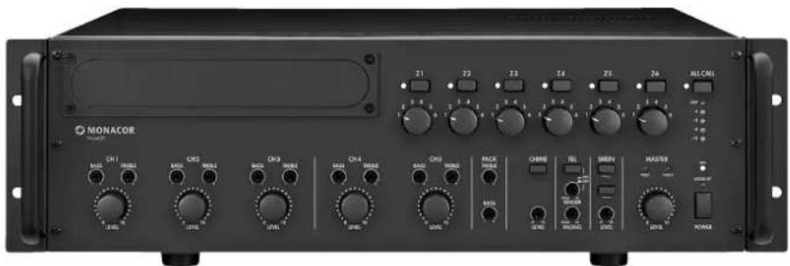
For remote control of the following functions connect a switch to the terminalsMESSAGE FIRST PRIORITY (28):
- All PA zones are switched on and set to maximum volume [as with the button ALL CALL (4)].
- When using the digital message insertion PA1120DMT, the announcement of the memory M 6 is automatically called. For this purpose, connect the jumper MS 2 prior to installing the insertion to the position "PRI TO PACK" (see layout plan on page 28). Thus, the announcement of the memory M 6 takes first priority.
Instead of the switch, it is also possible to connect an alarm detecting contact, e.g. for an automatic fire alarm announcement.
- If the amplifier is at the same time to be switched on by the switch or alarm detecting contact, connect a diode of type 1N4007 according to fig. 7 between the upper terminalMESSAGE FIRST PRIORITY and the left terminal POWER REM.
Automatic switch-on of the amplifier and activation of the announcement M 6
5.3.10 Emergency priority relays
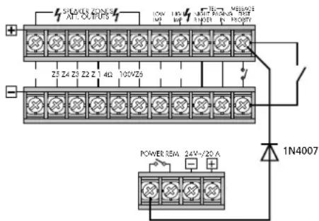
If PA volume adjusting controls with emergency priority relays (e.g. series ATT-3..PEU or ATT-5..PEU from MONACOR) are inserted between the amplifier and the speakers, important announcements can also be heard at the volume "zero".
1) For this purpose connect a desk microphone PA-4000PTT or PA-4300PTT (chap.5.3.3).
2) Connect the emergency priority relay according to fig. 8 to the terminals PRIORITY RELAY OUTPUT (47). The output allows a load of 200mA
3) Set the switch PRIORITY at the microphone to position ON (downwards).
4) When actuating the TALK button now, the speakers are set to maximum volume by the relays.
Emergency priority relays
5.3.11 Switch for switching on and off by remote control
The amplifier can be switched on and off by remote control with a switch connected to the contacts POWER REM (36). For this purpose, the amplifier must not be switched on with the POWER switch (19) or not be connected to the emergency power supply.
5.3.12 Power supply and emergency power supply
1) Finally connect the supplied mains cable to the mains jack (35) first and then to a socket (230V / 50Hz)
2) For continuous operation of the amplifier in case of a possible mains failure, connect a 24V emergency power supply unit (e.g. PA-24ESP from MONACOR) to the terminals 24V = (37) . With a cable length of up to 6m , a cable cross section of 4mm^2 is required as a minimum.
Note:
- If the 24V voltage from the emergency power supply unit is present at the terminals 24V_ext , the amplifier cannot be switched off with the switch POWER (19). In case of a mains failure or if it is switched off, it switches automatically to the emergency power supply.
- Even if the amplifier is switched off, it consumes some power. Therefore, disconnect the mains plug from the socket and, if necessary, disconnect the emergency power supply unit if the amplifier will not be in operation for a longer time.
5.4 Defining the priority of the input signals
A priority is assigned to all input signals. A signal of a higher priority always covers a signal of a lower priority when both signals are present at the amplifier at the same time. Signals of the same priority are mixed. The following table gives an overview and shows possibilities of modification.
| Priority Signal | Condition | Modification | |
| 1 | Announcement M6 from digital message insertion PA-1120DM | jumper MS 2 on PRI TO PACK | |
| switch at (28) closed | |||
| 2 | desk microphone PA-4000PTT PA-4300PTT | DIP switch PRIORITY on microphone to ON | switch to OFF = 4thpriority2 |
| zone paging microphone PA-6000RC | switch on connection module to PRIORITY | switch to SLAVE = 4thpriority2 | |
| chime | — | — | |
| 3 | telephone switch-board at terminal (27) | — | — |
| 4 | inputs 1, 2 and 3 | DIP switch (34) to OFF1 | DIP switch to ON = 3rdpiarity |
| siren | — | — | |
| 5 | extension insertions | jumper MS 2 to SLAVE1 | jumper MS 2 to PRI TO PACK = 2ndpiarity |
| inputs 4 and 5 | — | — | |
| telephone bell or night bell | — | — | |
Factory setting
The desk microphone PA-4000PTT/PA-4300PTT uses the input 1 and the zone paging microphone PA-6000RC the input 2. Via the corresponding DIP switch MIC PRIORITY (34), the microphones can also be set to 3^d priority.
6 Operation
If the amplifier is switched off and if no 24V voltage from an emergency power supply unit is present at the terminals 24V = (37) , the LED STAND-BY (20) lights up.
1) Prior to the first switching-on, set the five level controls (7) for the inputs 1 to 5 and the control MASTER (17) to position zero for the time being.
2) Switch on the amplifier with the POWER switch (19) or with a switch connected to the terminals POWER REM (36). The green LED STAND-BY extinguishes and the yellow LED POWER (21) lights up.
6.1 Adjusting the volume
1) First adjust the volume desired as a maximum for announcements of highest priority. For this purpose, press the button ALL CALL (4) for the time being. According to the equipment available, make an announcement:
a) With a digital message insertion, call the announcement from the memory M6 via a switch at the terminalsMESSAGE FIRST PRIORITY (28). Set the control LEVEL at the insertion approximately to the position 7.
b) With a desk microphone connected to the jack PA-4300PTT (45) or PA-4000PTT (46), set the level control (7) of the input 1 approximately to the position 7, and make an announcement.
c) In case of a zone paging microphone PA6000RC, set the level control (7) of input 2 approximately to position 7, press the button ALL CALL (58), and make an announcement.
d) When using another microphone, set the level control (7) of the corresponding input approximately to position 7, and make an announcement.
2) During an announcement, adjust the volume with the control MASTER (17). In case of overload, the red LED CLIP lights up in the level indication (5). Then reduce the volume with the control MASTER.
3) To adjust the volume for normal announcements, disengage the button ALL CALL again. For this purpose, press all buttons (3) of the individual PA zones.
4) Make an announcement as described under item 1) b or d.
Notes:
- On the PA-4000PTT /PA-4300PTT, set the switch PRIORITY to the upper position.
- Do not make the announcement via a PA-6000RC because its volume is independent of the zone volume switches (2).
5) Do not change the control MASTER (17) but adjust the desired volume separately for each zone with the corresponding zone volume switches (2) during the announcement.
6) Then adjust the volume for the signals of the other inputs (e.g. background music) with the control LEVEL (7) of the corresponding input.
7) For each input used adjust the sound with the corresponding controls "Bass" and "Treble" (6). Adjust the sound for an insertion in the compartment (1) with the controls PACK (8).
8) It may be necessary to readjust once again the volume of the input signals with the corresponding level controls (7).
9) Turn the level controls (7) of the inputs not used to zero.
Note: For the inputs 1 to 3, the input sensitivity can be adjusted with the controls GAIN (43), if a level control (7) must be turned up very far or almost be closed to obtain the desired volume ratio to the other inputs, modify the input sensitivity with the corresponding control GAIN.
6.2 Activating the PA zones
1) Switch on the zones to be used for PA applications with the buttons Z 1-Z6 (3). As a check, the green LEDs of the activated zones light up.
2) For announcements to all zones, press the button ALL CALL (4). At the same time, the volume of the zones is increased to maximum [corresponds to the adjustment of all zone volume switches (2) in position 6].
6.3 Chime
The chime sounds prior to an announcement when the TALK button at the desk microphone PA-4000PTT / PA-4300PTT or at the zone paging microphone PA-6000RC is pressed. When other microphones are used, the chime can be activated with the button CHIME (9). Adjust the chime volume with the control LEVEL (10).
With the jumper MS 1, it is possible to switch between a 2-tone chime and a 4-tone chime, see chapter [5.2].
6.4 Alarm siren
In case of an alarm it is possible to switch the siren on with one of the two buttons (15) in the control section SIREN:
Button for a wailing tone
Button - - " for a continuous tone
Adjust the volume of the alarm siren with the control LEVEL (14).
6.5 Zone paging microphone PA-6000RC
1) First switch on the PA zones in which the announcement are to be heard with the buttons SPEAKER ZONES SELECTOR (57), otherwise no announcement will be possible. To activate all zones, press the button ALL CALL (58).
2) For the announcement, keep the TALK button (55) pressed. The amplifier activates the PA zones according to the preselection under item 1) independent of the adjustments at the amplifier and increases the volume in the zones to maximum [corresponds to the adjustment of all zone volume switches (2) to position 6]. After the chime, make the announcement.
3) When using the digital message insertion PA-1120DMT, a stored announcement can also be called via the zone paging microphone if the switch DIGITALMESSAGE (48) is in position ON:
a) Select the stored announcement with the selector switchMESSAGE BANK (56).
b) Start the announcement with the button START/ STOP (60). To stop the announcement, press the button START/ STOP again.
c) With the button REPEAT/ STOP (59), an announcement can also be made several times. The number of repeats can be adjusted on the insertion (see its operating instructions). To stop the announcement, press the button REPEAT/STOP again.
Notes:
- The announcement of the memory M 6 may be locked (see chapter 4.1., item 9). If in this case the switchMESSAGE BANK is in position 6, the announcement last selected is reproduced.
- If at least one zone button (3) has been pressed at the amplifier, after releasing the TALK button, the announcement selected with the
switchMESSAGE BANKislikewisestarted.To prevent this,leave a storage location of the digital message insertion free or delete it and select this storage location with the switchMESSAGE BANK.
4) The three LEDs POWER, SEND, and BUSY (54) give the following information:
POWER lights up when the amplifier is switched on
SEND lights up when an announcement is reproduced via the microphone or a stored announcement is called
BUSY lights up with individual announcements and with announcements via other connected microphones PA-6000RC
6.6 Desk microphone PA-4000PTT/PA-4300PTT
1) With the microphone PA-4000PT or PA-4300PTT connected, the input 1 is no longer available. As the microphone requires phantom power for operation, press the switch PHANTOM POWER (44) of input 1.
2) If the chime is to sound prior to an announcement when the button TALK is pressed, set the switch CHIME on the rear side of the microphone to the position ON (downwards).
3) Set the switch PRIORITY to position ON when:
- the microphone is to take 2^rd priority
- all PA zones are to be switched on and set to maximum volume when pressing the TALK button [as with button ALL CALL (4)]
- the connected emergency priority relays are to respond (see chapter 2.5.10)
4) For an announcement keep the TALK button pressed and wait for the chime, if necessary.
7 Protective Circuit
The amplifier is equipped with a protective circuit against overload, overheating and short circuit at the speaker outputs. The power amplifier is cooled with a fan whose rotation speed depends on the temperature of the power amplifier. If in spite of this the temperature should increase too much, the amplifier is muted and the red LED PROTECT (16) lights up. In this case turn the control MASTER (17) fully to zero, wait until the LED PROTECT is extinguished, and then switch off the amplifier. Eliminate the fault, e.g.:
- In case of overload, reduce the number of speakers connected or, if possible, adjust a lower power consumption on the speakers. Insert a second PA amplifier, if required (see chapter 5.3.6).
- In case of overheating, provide a better air circulation.
- In case of short circuit at a speaker output, locate the position of the short circuit and eliminate it.
8 Specifications
Rated power
100V outputs*: 6 x 100W, however altogether not more than 240W (PA-6240) 480W (PA-6480) 600W (PA-6600)
4Ω output*
PA-6240: 1×240W
PA-6480:1×480W
PA-6600: 1×600W
Max. output power
PA-6240: 340W
PA-6480: 680W
PA-6600: 850W
THD: < 1% at 1 kHz
Inputs
Input sensitivity/ impedance; connection
MIC/LINE 1-3: 2.5-300mV adjustable/5kΩ; XLR/6.3 mm jack, bal
LINE 4 and 5: 300mV/15 kΩ; RCA, unbal.
AMP IN: 775mV/10kΩ; 6.3 mm jack, unbal.
PAGING IN: 250mV/5kΩ; bal.
Extension insertion: 250 mV/10 kΩ; unbal.
Outputs
Speakers*
Zones: 6 × 100V
Direct outputs: 1 × 100V, 1 × 4Ω
RE OUT: 775 mV/100Ω; unbal.
EC: 775mV/3kΩ; unbal.
Frequency range: 55-16000 Hz (-3 dB)
S/N ratio
Line: >80 dB (A weighted)
Mic: >70 dB (A weighted)
Equalizer
bass: ±10 dB/100 Hz
treble: ±10dB/10kHz
Ambient temperature: .. 0-40°C
Power supply
mains voltage: 230V/50Hz
power consumption
PA-6240: 750VA
PA-6480: 1500VA
PA-6600: 1700VA
Emergency power supply
PA-6240: = 24V / 20A
PA-6480:24V/40A
PA-6600: 24V/50A
Dimensions (W× H× D) .. 482× 133× 352mm
3 rack spaces
Weight
PA-6240: 17.0kg
PA-6480: 19.5kg
PA-6600: 20.0kg
*Either use the 100V outputs or the 4 output!
Subject to technical modification.
1.3 Microphone commande PA-6000RC
6.5 Microphone commande PA-6000RC
| MIC/LINE 1-3: | 2,5-300mV |
| ajustable/5kΩ; | |
| XLR/6,3mmjack, sim |
LINE 4 y 5: 300 mV/15 kΩ; RCA, asim.
AMP IN: 775mV/10kΩ; 6,3mm jack, asim.
PAGING IN: 250 mV/5 kΩ; sim.
Modulo de insertion: 250mV/10kΩ; asim.
Salidas
Altavoces*
Zonas: 6×100V
Salidas directas: 1x100V, 1x4Ω
RE OUT: 775mV/100Ω; asim.
EC: 775 mV/3 kΩ; asim.
Rango de frequencies: 55-16000Hz (-3 dB)
LINE 4-5: 300mV/15kΩ;
RCA,niezbal.
AMP IN: 775mV/10kΩ
jack 6,3 mm,niezbal.
PAGING IN: 250mV/5kΩ bal.
Dodatkowe: 250mV/10kΩ niezbal.
Wyjscia
Glosnikowe*
Strefy: 6 × 100V
Bezposrednie wyjscie: 1× 100V 1× 4
PRE OUT: 775mV/100Ω niezbal.
REC: 775mV/3kΩ niezbal.