W10606694A - Tumble drier WHIRLPOOL - Free user manual and instructions
Find the device manual for free W10606694A WHIRLPOOL in PDF.

User questions about W10606694A WHIRLPOOL
0 question about this device. Answer the ones you know or ask your own.
Ask a new question about this device
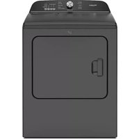
Download the instructions for your Tumble drier in PDF format for free! Find your manual W10606694A - WHIRLPOOL and take your electronic device back in hand. On this page are published all the documents necessary for the use of your device. W10606694A by WHIRLPOOL.
USER MANUAL W10606694A WHIRLPOOL
Installation Instructions
for W10606694 L.P. (Propane and Butane)
Gas Conversion Kit
Converting 20,000 BTU/hr Gas Burners from Natural Gas to Liquefied Petroleum (Bottled Gas)
Parts included in Kit:
1 Instruction Sheet
1 Blocking Pin
1 Orifice, Burner-Butane No. .049
1 Orifice, Burner-Propane No. 55
1 Label, Rating Plate Conversion (English)
1 Label, Rating Plate Conversion (French)
1 Label, Conversion Record (English)
1 Label, Conversion Record (French)
1 Label, Burner Baseplate (English/French)
Tools and Accessories required:
1/4" Socket and Ratchet Wrench
1/4" Nut Driver
5/16" Nut Driver
Phillips-Head Screwdriver
T-20 Torx -head Screwdriver
Pliers or Flat-Head Screwdriver
| Disassembling the Dryer | |||||
| Section | Cabinet Width | Console Location | Front Panel Type | Rated Capacity (cubic feet) | Page |
| 1 29" Rear Full 8.8+ 2 | |||||
| 2 27" Front | Full | 7 to 7.5 | 4 | ||
| 3 29" Rear Full | 7 to 7.6 | 8 | |||
| 4 27" Rear Toe | Panel | 7 to 7.5 | 9 | ||
Warning: This conversion kit shall be installed by a qualified service agency in accordance with the manufacturer's instructions and all applicable codes and requirements of the authority having jurisdiction. The information in these instructions must be followed to minimize the risk of fire or explosion or to prevent property damage, personal injury, or death. The qualified service agency is responsible for the proper installation of this kit. The installation is not proper and complete until the operation of the converted appliance is checked as specified in the manufacturer's instructions supplied with this kit.
NOTE: A qualified service technician is any person or representative of a company who is experienced or trained in servicing gas equipment and is familiar with necessary precautions.
Canada Only
THIS CONVERSION KIT SHALL BE CARRIED OUT IN ACCORDANCE WITH THE REQUIREMENTS OF THE PROVINCIAL AUTHORITIES HAVING JURISDICTION AND IN ACCORDANCE WITH THE REQUIREMENTS OF THE CAN-B49.1 AND CAN1-B149.2 INSTALLATION CODE.
NOTE: Read these instructions before proceeding.
IMPORTANT: The LP Conversion Kit you received is an approved kit for converting your gas dryer from natural to LP propane or butane gas. The kit number shown on the Burner Data Label located on the Burner Base may not match the kit you receive due to kit consolidation.
Torx and T-20 are registered trademarks of Acument Intellectual Properties, LLC.
W10740674A
This dryer has been manufactured for use with Natural Gas. Installation of this conversion kit converts the dryer for use with L.P. gas with supply pressure between 8" (203 mm) and 13" (330 mm) water column. If this dryer is converted for use with L.P. gas by means of this kit, the input rating will be 20,000 BTU's per hour, for altitudes up to 10,000 feet (3,048 m). For installations above 2,000 feet (610 m), contact a qualified service agency for derating instructions.
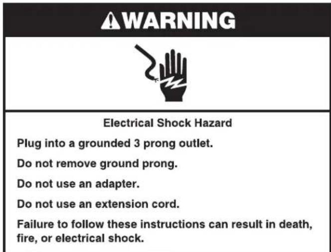
WARNING

Electrical Shock Hazard
Disconnect power before servicing.
Replace all parts and panels before operating.
Failure to do so can result in death or electrical shock.
Preparing for Kit Installation
READ THOROUGHLY AND FOLLOW STEPS
- Unplug dryer or disconnect power.
- Turn off gas supply using the shut-off valve that supplies the dryer.
- Fill out information on the appropriate Conversion Record Label (English or French) and apply in a conspicuous location adjacent to model and serial tag located in the door well. Go to Section 1, 2, or 3, depending on model.
Disassembling the Dryer
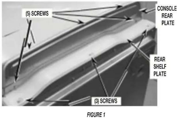
SECTION 1 - 8.8+ CUBIC FOOT MODELS WITH 29" CABINET, FULL FRONT PANEL, AND REAR CONSOLE
To gain access to inside of dryer:
- Remove console rear plate and rear shelf plate by removing a total of eight (8) screws. See Figure 1.
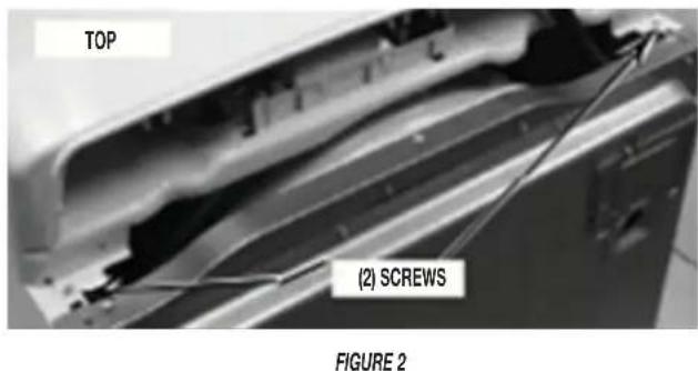
- Remove two (2) screws from the rear of the top.
See Figure 2. This will allow the top to be slid rearward.
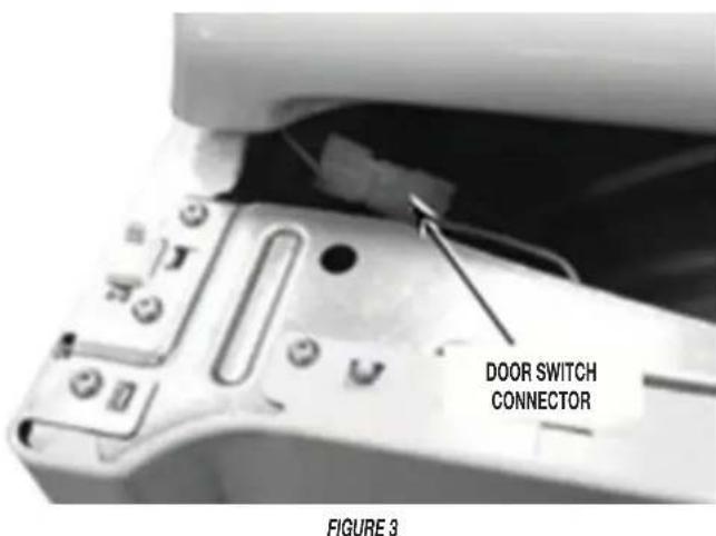
- Disconnect the door switch connector located in the top left front corner of the dryer. See Figure 3.
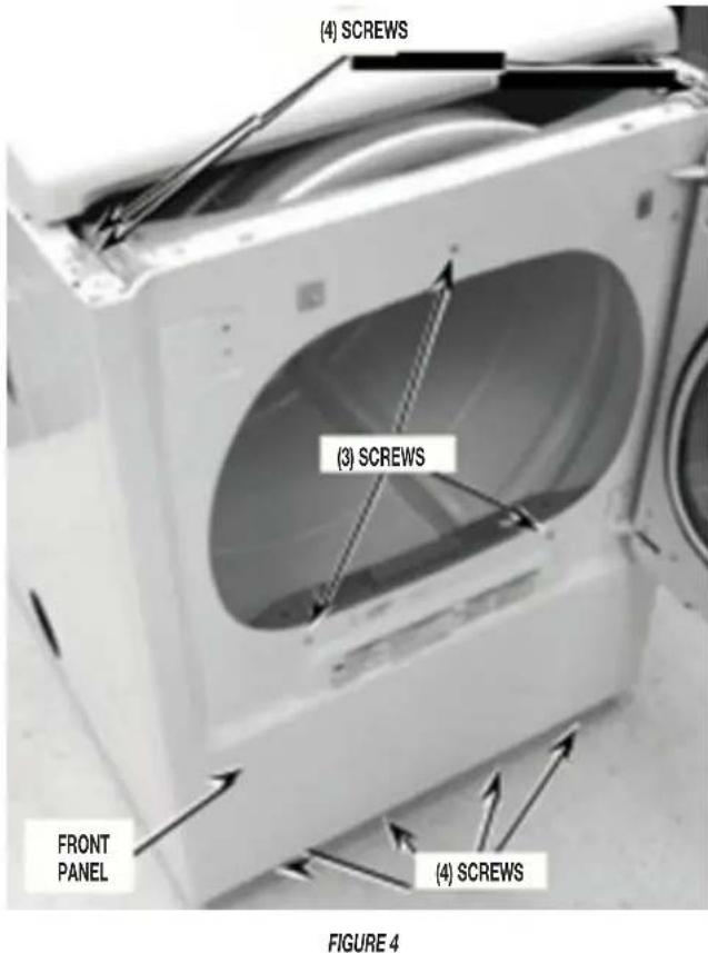
- Remove the front panel and door assembly by removing a total of eleven (11) screws: Four (4) 14 hex-head screws along the bottom front, three (3) Phillips-head screws around the door opening, and four (4) T-20 Torx-head screws on the top front panel bracket. See Figure 4. Once screws are removed, close the door and lift up the front panel and door assembly to remove.
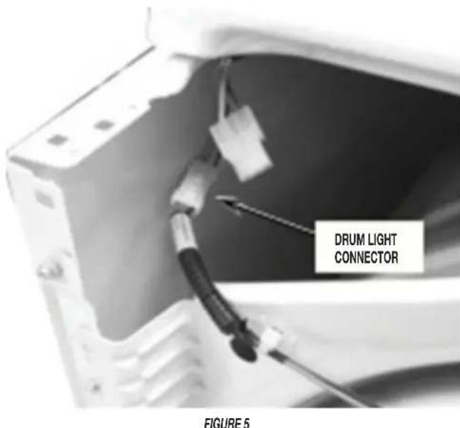
- Disconnect the drum light connector located in the top left front corner of the dryer. See Figure 5.
- Disconnect moisture strip connector located in lower right front corner of the dryer. See Figure 6.
- Remove the two (2) lower lint duct screws. See Figure 6.
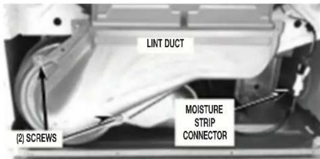
FIGURE 6
- Remove the four (4) screws from the two side edges of the front bulkhead. See Figure 7.
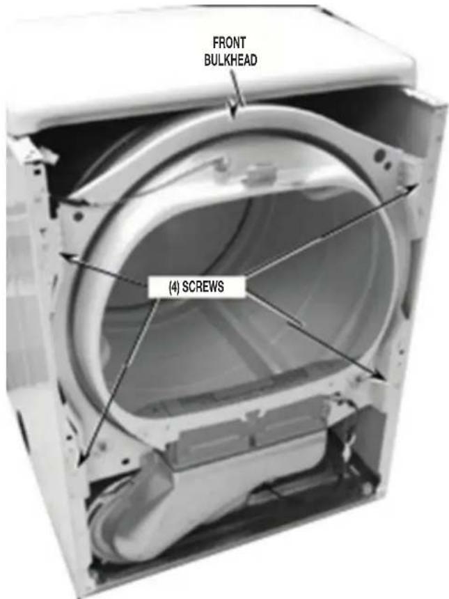
FIGURE 7
- Remove the front bulkhead and lint duct assembly by lifting it off the two (2) front hooks (see Figure 8) and then lowering it to clear the drum support rollers from the drum front.
NOTE: Lift up on front of drum to help lift off of rollers on front bulkhead.
NOTE: Since the drum belt is still in tension, it will pull the drum down as you remove the front bulkhead and lint duct assembly.
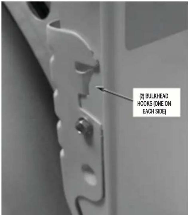
FIGURE 8
- Remove the drum belt tension by reaching into dryer just under the drum to back side of drive motor. Grasp idler pulley and lift up to relieve tension from belt and remove belt from motor pulley and lower the idler slowly. See Figure 9.
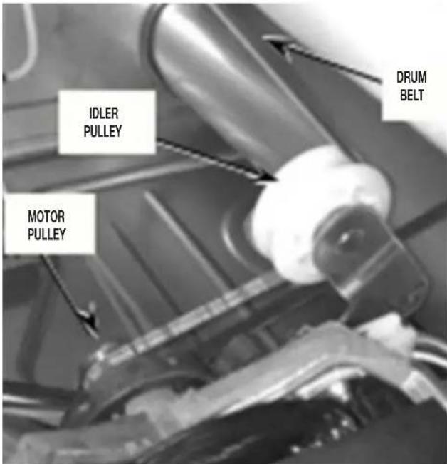
FIGURE 9
- Remove drum from the dryer by grasping the top of the drum belt and front of drum while sliding drum out of cabinet front.
FIGURE 10
- Remove the front bulkhead and lint duct assembly by lifting it. Continue to "Determining Gas Valve Style" - "Changing the Orifice."
SECTION 2 - 7 TO 7.5 CUBIC FOOT MODELS WITH 27^ CABINET, FULL FRONT PANEL, AND FRONT CONSOLE
- Remove dryer top by first removing the two (2) screws from the rear of the dryer. See Figure 1.
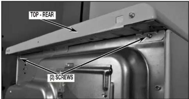
FIGURE 1
- Remove dryer top by sliding top toward rear of dryer and lift to remove. See Figure 2.
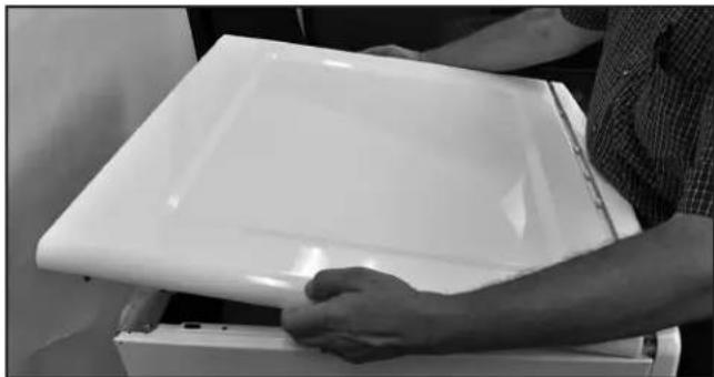
FIGURE 2
- Remove console by first removing two (2) screws (one from each side of console assembly) at location as shown in Figure 3.
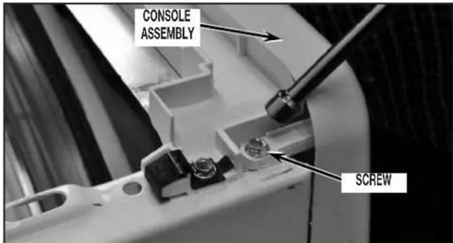
FIGURE 3
- Disconnect drum light connector and main console connector as shown in Figure 4. Lift up on console and tilt assembly forward to remove console. NOTE: Only on models with the CCU Bracket located on the left side of the unit.
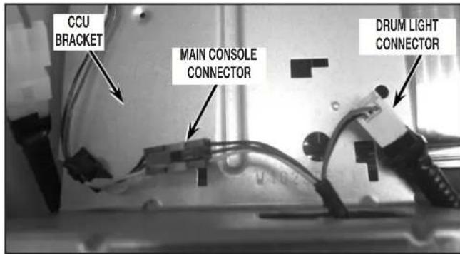
FIGURE 4
- Remove front panel assembly by opening door and remove the two (2) screws as shown in Figure 5. After removal of these screws, close door.
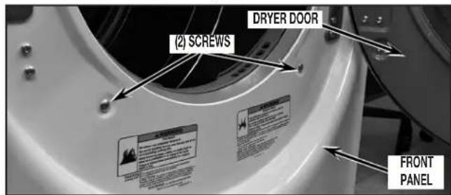
FIGURE 5
- Disconnect door switch connector. See Figure 6.
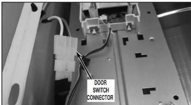
FIGURE 6
- Remove front panel by first removing four (4) screws from bottom of front panel as shown in Figure 7.
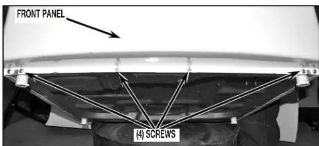
FIGURE 7
- Next remove the three (3) screws from the top of the front panel as shown in Figure 8.
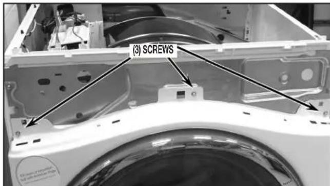
FIGURE 8
- Remove front panel assembly from dryer by lifting panel assembly up and off tabs (one each side) as shown in Figure 9.
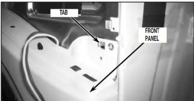
FIGURE 9
- Next remove console mounting bracket by removing two (2) screws securing bracket to cabinet left side panels, two (2) screws from right side panel and one (1) screw from central controlbracket.Slightlyliftassemblyandremovefromdryer. See Figures 10A and 10B.
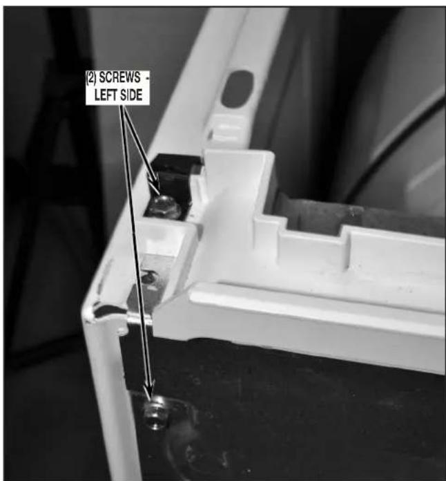
FIGURE 10A
NOTE: Only on models with the CCU Bracket located on the left side of the unit.
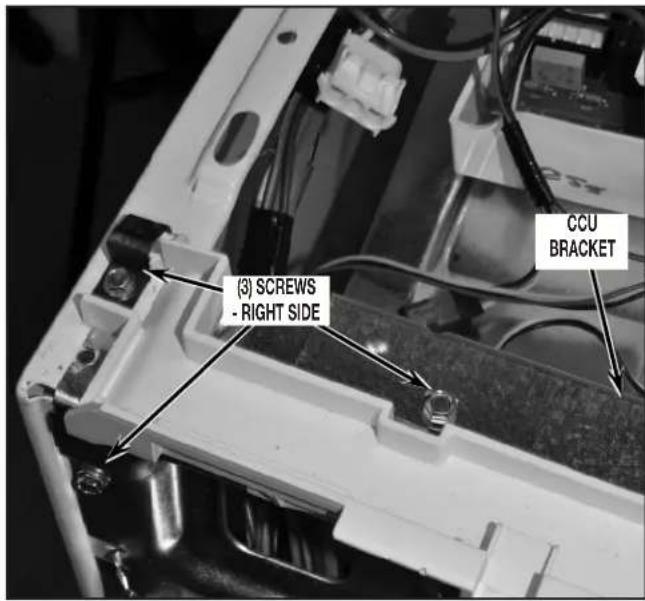
FIGURE 10B
- Remove the bulkhead assembly from dryer by first removing lint screen from dryer lint duct. See Figure 11.
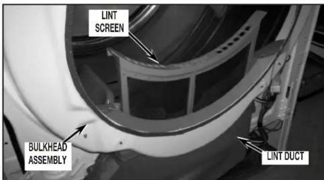
FIGURE 11
- Disconnect moisture sensor disconnect block from main harness disconnect block located at lower right side of dryer. See Figure 12.
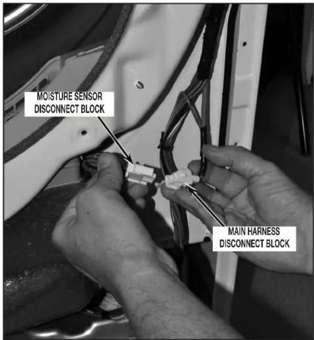
FIGURE 12
- Remove lint duct by removing the four (4) screws and clip as shown in Figure 13.
NOTE: Slide lint duct down and away from dryer to remove.
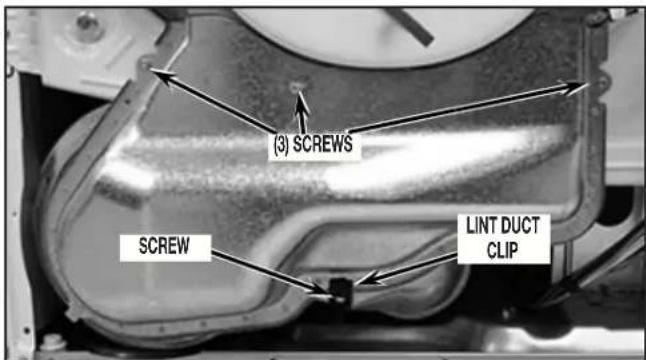
FIGURE 13
- Remove bulkhead assembly by first removing four (4) screws securing the bulkhead assembly to cabinet. Slightly lift up on bulkhead assembly and at the same time pulling away from drum working rollers off drum. See Figure 14.
NOTE: During removal of bulkhead, take special notice of the Lower Protective Shield to ensure proper orientation during reassembly.
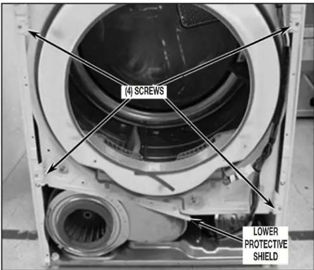
FIGURE 14
- Swing bulkhead assembly to side and remove two (2) harness clips to disconnect harness from bulkhead. See Figure 15. NOTE: Only on models with the CCU Bracket located on the right side of the unit.
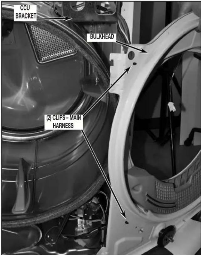
FIGURE 15
- To gain further access to the burner assembly the drum will need to be removed. Before removing drum from dryer the CCU and bracket assembly must be secured in position to side panel using the plastic hook attached to the main harness. This will allow the CCU assembly to hang in place rather than dropping down when the drum is removed. See Figure 16.
NOTE: Only on models with the CCU Bracket located on the right side of the unit.
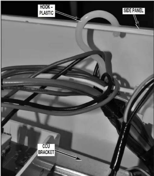
FIGURE 16
- Remove drum from dryer by first reaching into dryer just under the drum, to back side of drive motor. Grasp idler pulley and lift up to relieve tension from belt and remove belt from motor pulley and idler pulley. Refer to Figure 17 for belt removal and reassembly.
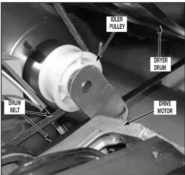
FIGURE 17
- Remove drum from dryer by grasping the drum belt and front of drum and slide drum out of cabinet front.
IMPORTANT: Note position of drum belt, front and rear orientation for reassembly. See Figure 18.
NOTE: When removing drum from cabinet be sure not to hit the CCU and bracket assembly knocking it from its hanging position. Continue to "Determining Gas Valve Style" - "Changing the Orifice."
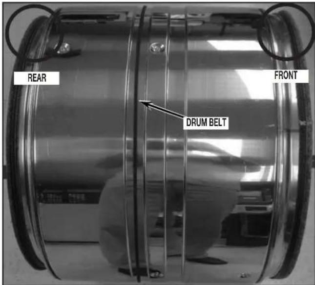
FIGURE 18
SECTION 3-7 TO 7.6 CUBIC FOOT MODELS WITH 29^ CABINET, FULL FRONT PANEL, AND REAR CONSOLE
- Lift dryer top. Use a putty knife to press against the left and right spring clips to release them from the top. Gently lean dryer top toward the wall so as not to damage the dryer top or wall. See Figure 1.
SPRING CLIPS FIGURE 1
- Remove two (2) hex head screws from the cabinet front panel. See Figure 2.
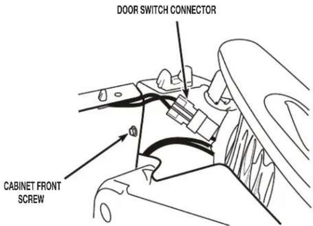
FIGURE 2
- Disconnect the door switch connector from the harness connector. See Figure 2.
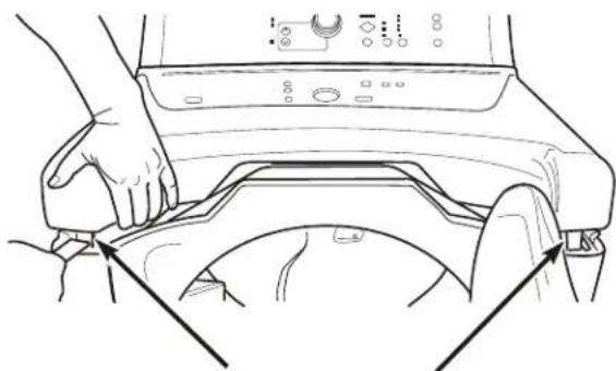
- Lift the front panel, unhook it from the bottom two hangers and remove the panel. See Figure 3.
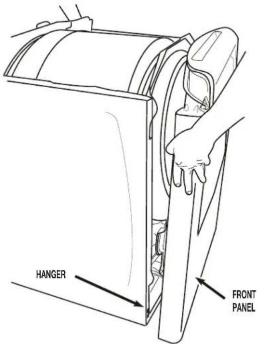
FIGURE 3
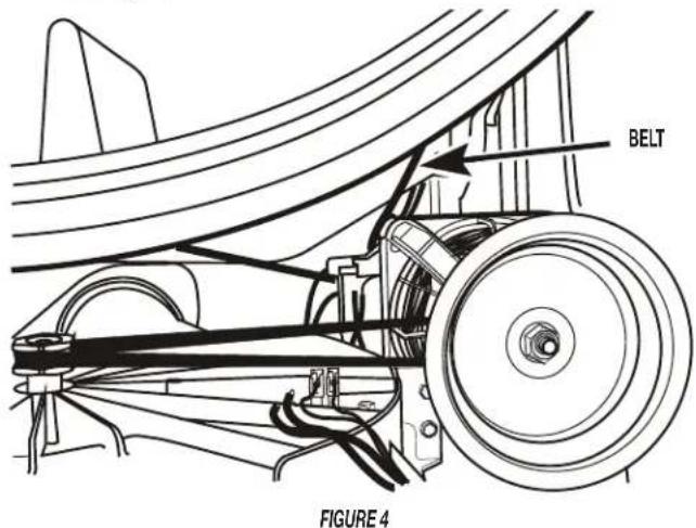
- Reach around the back of the drive motor and push the idler wheel arm to relieve the spring tension on the belt; then slide the belt off the idler and motor pulleys. See Figure 4.
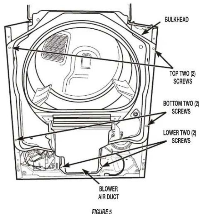
- Loosen the top two (2) hex-head screws and remove the bottom two (2) hex-head screws from the front bulkhead. Remove the lower two (2) screws from the blower air duct. Gently remove the bulkhead and blower air duct from the front of the dryer. See Figure 5.
- Remove the drum from the dryer cabinet.
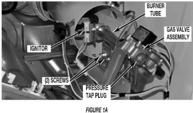
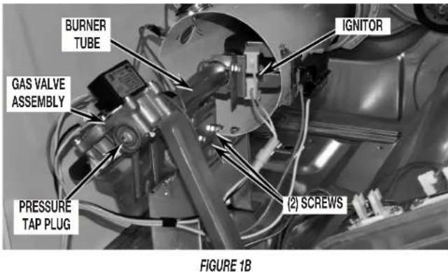
- Disconnect ignitor wires from harness then remove the burner tube by removing the two (2) screws securing it to the burner base. See Figure 1B; then continue to "Determining Gas Valve Style" - "Changing the Orifice."
SECTION 4-7 TO 7.5 CUBIC FOOT MODELS WITH 27^ CABINET, TOE PANEL, AND REAR CONSOLE
Disassemble to access gas valve. To remove the toe panel on some models, a small flat-head screwdriver is required to release the clips at top of panel. Continue to "Determining Gas Valve Style" - "Changing the Orifice."
Determining Gas Valve Style CHANGING THE ORIFICE (BOTH STYLES)
- Remove the two (2) screws securing the burner tube to the burner base. See Figures 1A and 1B.
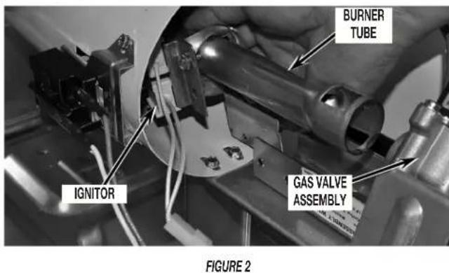
- Slide burner tube forward far enough to gain access to orifice. Do not bump ignitor. See Figure 2.
NOTE: The ignitor is fragile.
- Remove the burner orifice from the gas valve assembly and replace it with the proper orifice furnished in this kit. Orifice number is stamped on one edge of the hex head of orifice. Securely tighten. See Figure 3.
Propane gas - Use Orifice No. 55.
Butane gas - Use Orifice No. .049.
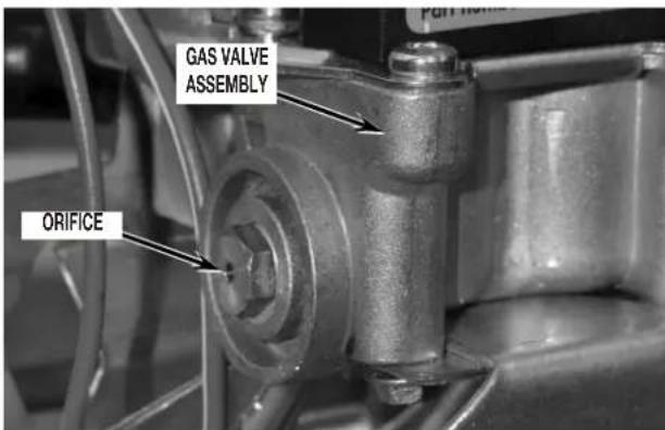
FIGURE 3
- Slide the burner tube back in place and, using the screws removed in Section 3, step 8, reattach burner tube to the burner assembly. Securely tighten the two (2) mounting screws. See Figure 1A or 1B.
- Before proceeding, you must first determine which gas valve style is on the dryer. Refer to Figure 4 - Style "A" and "B".
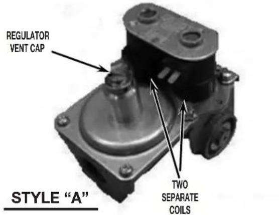
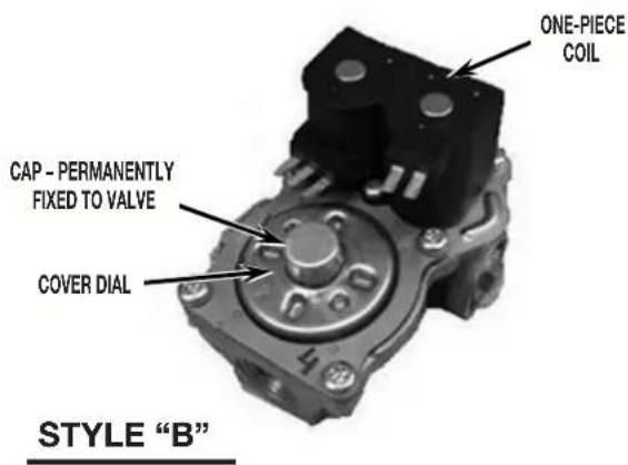
FIGURE 4
NOTE: IF YOUR GAS DRYER HAS STYLE "A" FOLLOW STEP 6. FOR STYLE "B" SKIP TO STEPS 7 TO 10.
STYLE “A” GAS VALVE CONVERSION
- Remove the regulator vent cap (leak limiting device) from the pressure regulator. See Figure 5. Continue to Step 10.
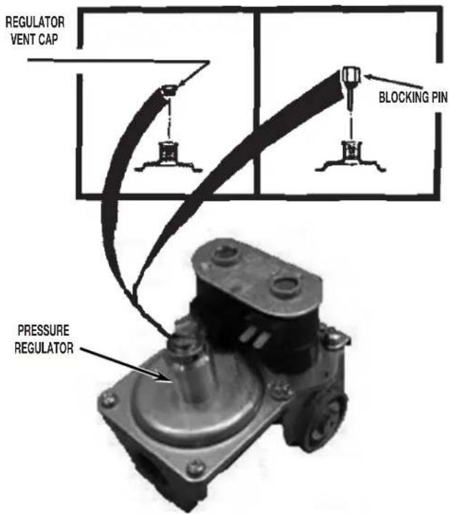
FIGURE 5
STYLE "B" GAS VALVE CONVERSION
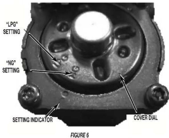
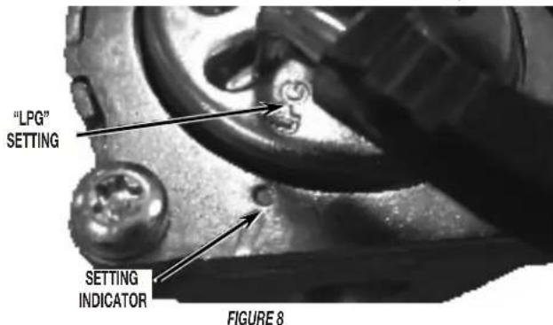
- Observe the cover dial settings indicated as NG (Natural Gas) and LPG (Liquefied Propane gas) along with the gas type setting indicator. See Figure 6.
- Position a pair of bend pliers into the slots of the cover dial. See Figure 7.
NOTE: To gain better access, remove the coil wire leads.
NOTE: If bend pliers are not available, a flat-blade screwdriver and/or needle nose pliers will suffice.
- Rotate cover dial 25 degrees counterclockwise, lining up "LPG" marking with the indicator on the gas valve. See Figure 8.
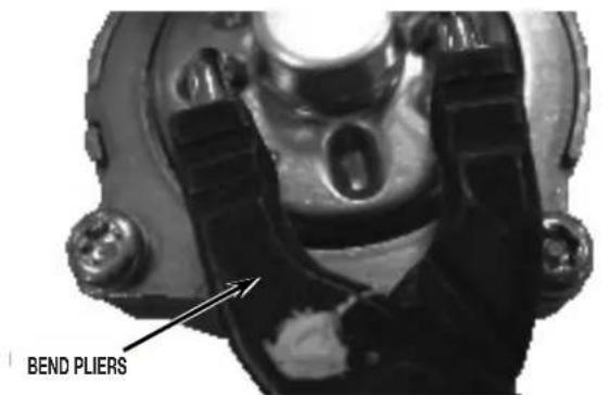
FIGURE 7
- Apply English or French conversion label on top of the burner data decal located on the burner baseplate.
Installation Checklist
- Check that both labels have been installed as described in "Preparing for Kit Installation," step 3 and Step 10 above.
- If converting to Propane, check that the number 55 is not marked on either of the remaining orifices. If converting to Butane, check that the number .049 is not marked on either of the remaining orifices.
WARNING
Explosion Hazard
Use a new CSA International approved gas supply line. Install a shut-off valve.
Securely tighten all gas connections.
If connected to LP, have a qualified person make sure gas pressure does not exceed 13" (330 mm) water column.
Examples of a qualified person include: licensed heating personnel, authorized gas company personnel, and authorized service personnel.
Failure to do so can result in death, explosion, or fire.
Pressure Testing (Both Styles)
Check minimum and maximum inlet gas pressure:
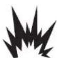
- Remove pressure tap plug from valve body using a 3/16" hex wrench. See Figure 1.
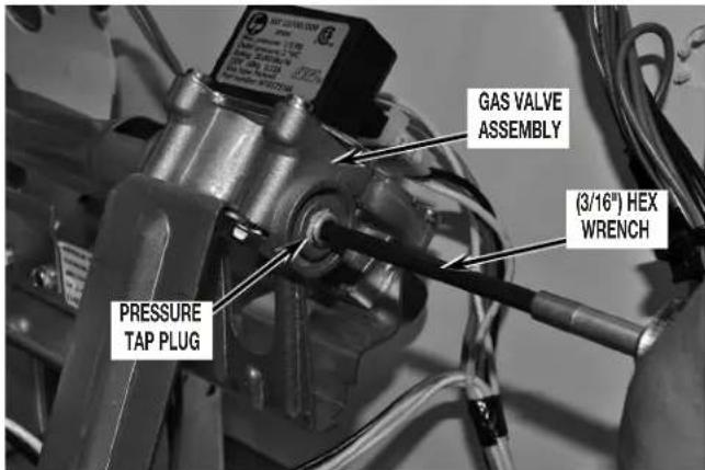
FIGURE 1
- Insert pressure tap and finger-tighten. Remove view hole plug from side panel. See Figure 2.
FIGURE 2
- Connect a airtight hose to pressure tap and run the hose through the view hole on the right side panel. Connect other end of hose to manometer (airtight hose will attach between pressure tap and manometer.) See Figure 3.
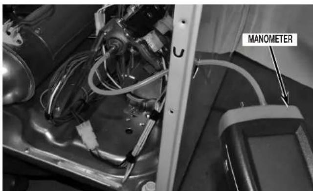
FIGURE 3
NOTE: Be sure to replace all parts a panels, and to reconnect all wire leads and connections that were disconnected during disassembly of dryer.
- Turn on and zero manometer. See Figure 4.
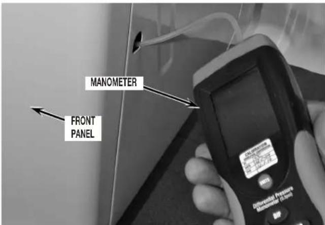
FIGURE 4
- Plug in dryer or reconnect power.
- Turn on gas supply.
- Set dryer cycle to time dry, high heat and turn on dryer.
- After ignition, verify gas inlet pressure is between 8'' (203 mm) and 13" (330 mm) water column.
- Turn off dryer.
- Unplug dryer or disconnect power.
- Turn off gas supply.
- Disassemble control panel or top and console assembly (depending on application) and front panel assembly from dryer to regain access to burner assembly.
- Disconnect manometer and remove hose from pressure tap.
- Remove pressure tap.
- Reinstall pressure tap plug to gas valve and tighten.
NOTE: Pressure tap plug can be reinstalled and securely tighten to gas valve body without removal of the bulkhead assembly with the use of a 3/16" hex wrench.
Checking for Leaks
- With front panel removed, brush or spray an approved non-corrosive leak detection solution onto pressure tap plug.
-
Reassemble dryer in reverse order as described in "Disassembling the Dryer."
-
Turn on gas supply.
- Plug in dryer or reconnect power.
- Set dryer cycle to time dry, high heat and turn on dryer.
- View through the hole on the right side panel inspecting for leaks indicated by growing bubbles. See Figure 1.
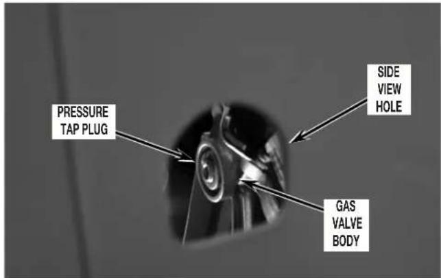
FIGURE 1
- If any bubbles are present, turn off gas supply, tighten the leaking connection and retest for leaks.
- If dryer was moved during conversion, use the same method to check for leaks in the flexible gas supply line and fittings between the dryer and the gas supply pipe.
- If any bubbles are present, tighten the leaking connection and retest for leaks.
NOTE: Replace flexible gas supply line if bubbles are present on supply line.
- If no bubbles are present, reinstall hole plug to side panel and unplug dryer.
Completing the Conversion
- Check to assure all components are attached securely in place and lint filter has been installed to dryer.
- Reattach dryer top or top and console assembly (depending on application). If dryer was moved from its original position, reposition dryer to its location.
- Connect external exhaust vent to dryer.
- Plug in dryer or reconnect power.
-
Check that dryer is working properly by:
-
Turning on dryer.
- Running on high heat for 5 minutes.
- Checking for heat in drum.