YWED4815EW - Tumble drier WHIRLPOOL - Free user manual and instructions
Find the device manual for free YWED4815EW WHIRLPOOL in PDF.

User questions about YWED4815EW WHIRLPOOL
0 question about this device. Answer the ones you know or ask your own.
Ask a new question about this device
Download the instructions for your Tumble drier in PDF format for free! Find your manual YWED4815EW - WHIRLPOOL and take your electronic device back in hand. On this page are published all the documents necessary for the use of your device. YWED4815EW by WHIRLPOOL.
USER MANUAL YWED4815EW WHIRLPOOL
Gas and Electric Dryer Installation Instructions
29" Wide Models
Tools and Parts....4
Location Requirements 5
ELECTRICAL REQUIREMENTS - U.S.A. ONLY
Electrical Requirements 7
ELECTRIC DRYER POWER HOOKUP - CANADA ONLY......8
Electrical Requirements 8
GAS DRYER POWER HOOKUP - U.S.A. AND CANADA......8
Electrical Requirements 8
Gas Supply Requirements....9
Install Leveling Legs 10
MAKE ELECTRICAL CONNECTION - U.S.A. ONLY
(EFFECTUER LE RACCORDEMENT ÉLECTRIQUE -
ÉTATS-UNIS SEULEMENT)....11
Electrical Connection Options....11
Power Supply Cord Connection....12
Direct Wire Connection....13
MAKE GAS CONNECTION....16
VENTING....17
Venting Requirements....17
Plan Vent System....18
Venting Kits....18
INSTALL VENT SYSTEM 19
CONNECT INLET HOSES....20
CONNECT VENT 21
LEVEL DRYER....21
COMPLETE INSTALLATION CHECKLIST 22
REVERSE DOOR SWING (OPTIONAL) 22
TROUBLESHOOTING....24
Table des matières
SÉCURITÉ DE LA SÉCHEUSE 25
EXIGENCES D'INSTALLATION 27
RACCORDEMENT DU CONDUIT D'ÉVACUATION .... 39
RÉGLAGE DE L'APLOMB DE LA SÉCHEUSE.... 39
ACHEVER L'INSTALLATION - LISTE DE VÉRIFICATION.....39
INVERSION DU SENS DE L'OUVERTURE DE LA PORTE
(FACULTATIF)......40
DÉPANNAGE 42
Date of installation:
Installer:
Model number:
Serial number:
NOTES CONCERNANT L'INSTALLATION
Date d'achat :
Your safety and the safety of others are very important.
We have provided many important safety messages in this manual and on your appliance. Always read and obey all safety messages.

This is the safety alert symbol.
This symbol alerts you to potential hazards that can kill or hurt you and others.
All safety messages will follow the safety alert symbol and either the word "DANGER" or "WARNING."
These words mean:
! DANGER
You can be killed or seriously injured if you don't immediately follow instructions.
WARNING
You can be killed or seriously injured if you don't follow instructions.
All safety messages will tell you what the potential hazard is, tell you how to reduce the chance of injury, and tell you what can happen if the instructions are not followed.

WARNING - "Risk of Fire"
- Clothes dryer installation must be performed by a qualified installer.
- Install the clothes dryer according to the manufacturer's instructions and local codes.
- Do not install a clothes dryer with flexible plastic venting materials or flexible metal (foil type) duct. If flexible metal duct is installed, it must be of a specific type identified by the appliance manufacturer as suitable for use with clothes dryers. Flexible venting materials are known to collapse, be easily crushed, and trap lint. These conditions will obstruct clothes dryer airflow and increase the risk of fire.
- To reduce the risk of severe injury or death, follow all installation instructions.
- Save these instructions.

WARNING
Fire Hazard
Failure to follow safety warnings exactly could result in serious injury, death, or property damage.
Do not install a booster fan in the exhaust duct.
Install all clothes dryers in accordance with the installation instructions of the manufacturer of the dryer.
In the State of Massachusetts, the following installation instructions apply:
■ Installations and repairs must be performed by a qualified or licensed contractor, plumber, or gasfitter qualified or licensed by the State of Massachusetts.
■ If using a ball valve, it shall be a T-handle type.
■ A flexible gas connector, when used, must not exceed 3 feet.
WARNING: For your safety, the information in this manual must be followed to minimize the risk of fire or explosion, or to prevent property damage, personal injury, or death.
- Do not store or use gasoline or other flammable vapors and liquids in the vicinity of this or any other appliance.
-
WHAT TO DO IF YOU SMELL GAS:
-
Do not try to light any appliance.
- Do not touch any electrical switch; do not use any phone in your building.
- Clear the room, building, or area of all occupants.
- Immediately call your gas supplier from a neighbor's phone. Follow the gas supplier's instructions.
- If you cannot reach your gas supplier, call the fire department.
- Installation and service must be performed by a qualified installer, service agency, or the gas supplier.
WARNING: Gas leaks cannot always be detected by smell.
Gas suppliers recommend that you use a gas detector approved by UL or CSA.
For more information, contact your gas supplier.
If a gas leak is detected, follow the "What to do if you smell gas" instructions.
IMPORTANT: The gas installation must conform with local codes, or in the absence of local codes, with the National Fuel Gas Code, ANSI Z223.1/NFPA 54 or the Canadian Natural Gas and Propane Installation Code, CSA B149.1.
The dryer must be electrically grounded in accordance with local codes, or in the absence of local codes, with the National Electrical Code, ANSI/NFPA 70 or Canadian Electrical Code, CSA C22.1.
IMPORTANT SAFETY INSTRUCTIONS
WARNING: To reduce the risk of fire, electric shock, or injury to persons when using the dryer, follow basic precautions, including the following:
■ Read all instructions before using the dryer.
■ Do not place items exposed to cooking oils in your dryer. Items contaminated with cooking oils may contribute to a chemical reaction that could cause a load to catch fire.
- Do not dry articles that have been previously cleaned in, washed in, soaked in, or spotted with gasoline, dry-cleaning solvents, or other flammable or explosive substances as they give off vapors that could ignite or explode.
■ Do not allow children to play on or in the dryer. Close supervision of children is necessary when the dryer is used near children.
■ Before the dryer is removed from service or discarded, remove the door to the drying compartment.
■ Do not reach into the dryer if the drum is moving.
■ Do not install or store the dryer where it will be exposed to the weather.
■ Do not tamper with controls.
■ Do not repair or replace any part of the dryer or attempt any servicing unless specifically recommended in this Use and Care Guide or in published user-repair instructions that you understand and have the skills to carry out.
■ Do not use fabric softeners or products to eliminate static unless recommended by the manufacturer of the fabric softener or product.
■ Do not use heat to dry articles containing foam rubber or similarly textured rubber-like materials.
■ Clean lint screen before or after each load.
- Keep area around the exhaust opening and adjacent surrounding areas free from the accumulation of lint, dust, and dirt.
■ The interior of the dryer and exhaust vent should be cleaned periodically by qualified service personnel.
■ See "Electrical Requirements" located in the installation instructions for grounding instructions.
SAVE THESE INSTRUCTIONS
IMPORTANT SAFETY INSTRUCTIONS
When discarding or storing your old clothes dryer, remove the door.
SAVE THESE INSTRUCTIONS
INSTALLATION REQUIREMENTS
Tools and Parts
Gather the required tools and parts before starting installation.
Tools needed for all installations:
natural_image
Line drawing of a screwdriver with a flat head and threaded shaft (no text or symbols)
natural_image
Simple line drawing of a screwdriver (no text or symbols)Flat-blade screwdriver #2 Phillips screwdriver
natural_image
Simple line drawing of a screwdriver with a handle and screw head (no text or symbols)1/4" nut driver or socket wrench (recommended)
natural_image
Line drawing of a pair of pliers (no text or symbols)Tin snips (new vent installations)
natural_image
Simple line drawing of a tape measure (no text or symbols)Tape measure
natural_image
Two interlocked rings with metal clips attached (no text or symbols)Vent clamps
natural_image
Simple diagram with three circular symbols inside a rectangular box (no text or labels)Level
natural_image
Line drawing of a pair of pliers (no text or symbols)Pliers

natural_image
Line drawing of an adjustable wrench (no text or symbols)Adjustable wrench that opens to 1" (25 mm) or hex-head socket wrench
natural_image
Two line drawings of laboratory pipettes: a cylindrical tube and a tool with a handle (no text or symbols)Caulking gun and compound (for installing new exhaust vent)
natural_image
Simple line drawing of a flat tool with a handle and central slot (no text or symbols)Utility knife
natural_image
Simple line drawing of a tool or plunger (no text or symbols)Putty knife
natural_image
Line drawing of a pair of pliers with metal handles (no text or symbols)Wire Stripper (direct wire installations)
Tools needed for gas installations:
natural_image
Line drawing of a adjustable wrench (no text or symbols)8" (203 mm) or 10" (254 mm) pipe wrench
natural_image
Line drawing of an adjustable wrench (no text or symbols)8" (203 mm) or 10" (254 mm) adjustable wrench (for gas connections)
natural_image
Simple line drawing of a jar with a lid and handle (no text or symbols)Pipe-joint compound resistant to LP gas
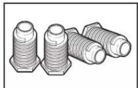
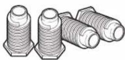
Parts supplied (all models):
natural_image
Illustration of four different types of bolts with hexagonal heads (no text or symbols)or
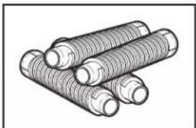
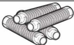
natural_image
Illustration of three cylindrical objects with textured surfaces (no text or symbols)Leveling legs (4) (Length and appearance of legs may vary according to model)
Parts supplied (steam models):
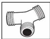
"Y" connector
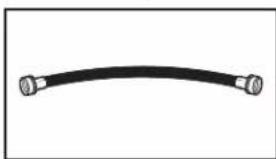
natural_image
Simple black curved line with two metallic connectors at both ends (no text or symbols)Short inlet hose
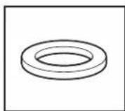
Rubber washer
Parts package is located in dryer drum. Check that all parts are included.
Parts needed (steam models):
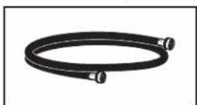
natural_image
Coiled black hose with two connectors (no text or symbols visible)5' (1.52 m) inlet hose
If using a power supply cord:
Use a UL listed power supply cord kit marked for use with clothes dryers. The kit should contain:
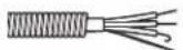
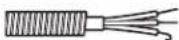
■A UL listed 30-amp power supply cord, rated 120/240 volt minimum. The cord should be type SRD or SRDT and be at least 4 ft. (1.22 m) long. The wires that connect to the dryer must end in ring terminals or spade terminals with upturned ends.
■A UL listed strain relief.
Parts needed: (Not supplied with dryer)
Check local codes. Check existing electrical supply and venting. See “Electrical Requirements” and “Venting Requirements” before purchasing parts.
Mobile home installations require metal exhaust system hardware available for purchase from the dealer from whom you purchased your dryer. For further information, please refer to the “Assistance or Service” section in your “Use and Care Guide.”
Optional Equipment: (Not supplied with dryer)
Refer to your "Use and Care Guide" for information about accessories available for your dryer.
Location Requirements
WARNING
Explosion Hazard
Keep flammable materials and vapors, such as gasoline, away from dryer.
Place dryer at least 18 inches (460 mm) above the floor for a garage installation.
Failure to do so can result in death, explosion, or fire.
You will need:
■A location allowing for proper exhaust installation. See "Venting Requirements."
■A separate 15 or 20-amp circuit needed for gas dryers and 30-amp circuit needed for electric dryers.
If you are using power supply cord, a grounded electrical outlet located within 2 ft. (610 mm) of either side of dryer. See "Electrical Requirements."
■A sturdy floor to support dryer and a total weight (dryer and load) of 200 lbs. (90.7 kg). The combined weight of a companion appliance should also be considered.
■Level floor with maximum slope of 1" (25 mm) under entire dryer. If slope is greater than 1" (25 mm), install Extended Dryer Feet Kit, Part Number 279810. If not level, clothes may not tumble properly and automatic sensor cycles may not operate correctly.
■ For garage installation, place dryer at least 18" (460 mm) above floor.
■Steam models only: Cold water faucet located within 4 ft. (1.2 m) of the water fill valves, and water pressure of 20-100 psi (137.9-689.6 kPa). You may use the water supply for your washer using the "Y" connector and short hose which are provided.
IMPORTANT: Do not operate, install, or store dryer where it will be exposed to water, weather, or at temperatures below 45^ F ( 7^ C). Lower temperatures may cause dryer not to shut off at end of automatic sensor cycles, resulting in longer drying times.
NOTE: No other fuel-burning appliance can be installed in the same closet as a dryer.
Installation clearances:
For each arrangement, consider allowing more space for ease of installation and servicing, spacing for companion appliances, and clearances for walls, doors, and floor moldings. Space must be large enough to allow door to fully open. Add spacing on all sides of dryer to reduce noise transfer. If a closet door or louvered door is installed, top and bottom air openings in door are required.
Check code requirements. Some codes limit, or do not permit, installation of the dryer in garages, closets, mobile homes, or sleeping quarters. Contact your local building inspector.
Dryer Dimensions
Front View
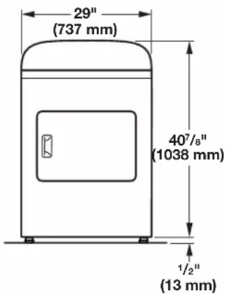
text_image
29" (737 mm) 407/8" (1038 mm) 1/2" (13 mm)NOTE: Minimum height of leveling legs should be 1/2" (13 mm), or to match the height of the accompanying washer.
Side View
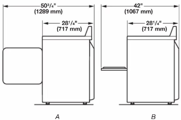
text_image
50³/⁴" (1289 mm) 28¹/⁴" (717 mm) 42" (1067 mm) 28¹/⁴" (717 mm) A BA. Wide opening side-swing door
B. Wide opening hamper door
Back View
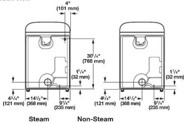
text_image
4" (101 mm) 30¼/4" (768 mm) 1¼/4" (32 mm) 4³/4" (121 mm) 14½" (368 mm) 9¼/4" (235 mm) 4¼/4" (121 mm) 14½" (368 mm) 9¼/4" (235 mm) Steam Non-SteamInstallation spacing for recessed area or closet
The dimensions shown are for the minimum spacing allowed.
■Additional spacing should be considered for ease of installation and servicing.
■Additional clearances might be required for wall, door, and floor moldings.
■ Additional spacing of 1" (25 mm) on all sides of the dryer is recommended to reduce noise transfer.
■For closet installation, with a door, minimum ventilation openings in the top and bottom of the door are required. Louvered doors with equivalent ventilation openings are acceptable.
■Companion appliance spacing should also be considered.
Installation Spacing
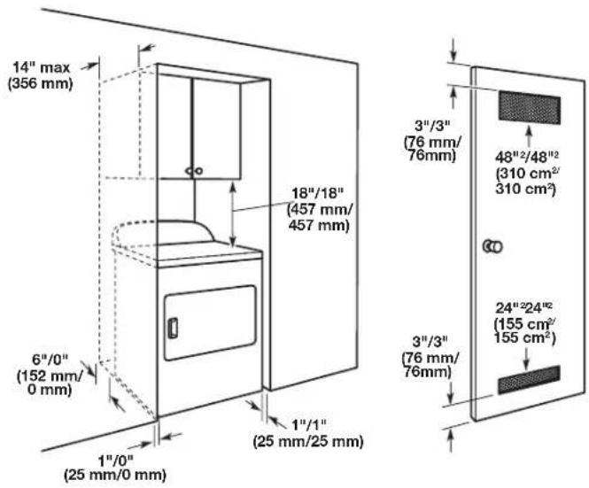
text_image
14" max (356 mm) 6"/0" (152 mm/ 0 mm) 1"/0" (25 mm/0 mm) 18"/18" (457 mm/ 457 mm) 1"/1" (25 mm/25 mm) 3"/3" (76 mm/ 76mm) 48"/2/48"/2 (310 cm²/ 310 cm²) 3"/3" (76 mm/ 76mm) 24"/24"/2 (155 cm²/ 155 cm²)Recommended/Minimum spacing
Mobile home – Additional installation requirements
This dryer is suitable for mobile home installations. The installation must conform to the Manufactured Home Construction and Safety Standard, Title 24 CFR, Part 3280 (formerly the Federal Standard for Mobile Home Construction and Safety, Title 24, HUD Part 280) or the Canadian Manufactured Home Standard CAN/CSA-Z240 MH.
■Metal exhaust system hardware, available for purchase. For further information, please reference the "Assistance or Service" section of the "Use and Care Guide."
■Special provisions must be made in mobile homes to introduce outside air into the dryer. The opening (such as a nearby window) should be at least twice as large as the dryer exhaust opening.
For gas dryers mobile home installations:
■Mobile Home Installation Hold-down Kit Part Number W10432680 is available to order. For further information, see "Assistance or Service" section in your "Use and Care Guide."
ELECTRICAL REQUIREMENTS - U.S.A. ONLY (SPÉCIFICATIONS ÉLECTRIQUES - ÉTATS-UNIS SEULEMENT)
Electrical Requirements
It is your responsibility:
■To contact a qualified electrical installer.
■To be sure that the electrical connection is adequate and in conformance with the National Electrical Code, ANSI/NFPA 70 - latest edition and all local codes and ordinances.
The National Electrical Code requires a 4-wire power supply connection for homes built after 1996, dryer circuits involved in remodeling after 1996, and all mobile home installations.
A copy of the above code standards can be obtained from: National Fire Protection Association, One Batterymarch Park, Quincy, MA 02269.
■To supply the required 3 or 4 wire, single phase, 120/240 volt, 60 Hz, AC only electrical supply (or 3 or 4 wire, 120/208 volt electrical supply, if specified on the serial/rating plate) on a separate 30-amp circuit, fused on both sides of the line. Connect to an individual branch circuit. Do not have a fuse in the neutral or grounding circuit.
■Do not use an extension cord.
■If codes permit and a separate ground wire is used, it is recommended that a qualified electrician determine that the ground path is adequate.
Electrical Connection
To properly install your dryer, you must determine the type of electrical connection you will be using and follow the instructions provided for it here.
This dryer is manufactured ready to install with a 3-wire electrical supply connection. The neutral ground conductor is permanently connected to the neutral conductor (white wire) within the dryer. If the dryer is installed with a 4-wire electrical supply connection, the neutral ground conductor must be removed from the external ground connector (green screw), and secured under the neutral terminal (center or white wire) of the terminal block. When the neutral ground conductor is secured under the neutral terminal (center or white wire) of the terminal block, the dryer cabinet is isolated from the neutral conductor.
■If local codes do not permit the connection of a neutral ground wire to the neutral wire, see "Optional 3-wire connection" section.
■A 4-wire power supply connection must be used when the appliance is installed in a location where grounding through the neutral conductor is prohibited. Grounding through the neutral is prohibited for (1) new branch-circuit installations, (2) mobile homes, (3) recreational vehicles, and (4) areas where local codes prohibit grounding through the neutral conductors.
If using a power supply cord:
Use a UL listed power supply cord kit marked for use with clothes dryers. The kit should contain:
■A UL listed 30-amp power supply cord, rated 120/240 volt minimum. The cord should be type SRD or SRDT and be at least 4 ft. (1.22 m) long. The wires that connect to the dryer must end in ring terminals or spade terminals with upturned ends.
■A UL listed strain relief.
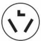
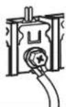
If your outlet looks like this:
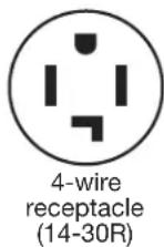
Then choose a 4-wire power supply cord with ring or spade terminals and UL listed strain relief. The 4-wire power supply cord, at least 4 ft. (1.22 m) long, must have 4 10-gauge solid copper wires and match a 4-wire receptacle of NEMA Type 14-30 R. The ground wire (ground conductor) may be either green or bare. The neutral conductor must be identified by a white cover.
If your outlet looks like this:
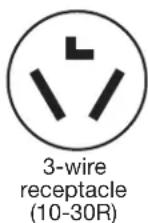
Then choose a 3-wire power supply cord with ring or spade terminals and UL listed strain relief. The 3-wire power supply cord, at least 4 ft. (1.22 m) long, must have 3 10-gauge solid copper wires and match a 3-wire receptacle of NEMA Type 10-30R.
If connecting by direct wire:
Power supply cable must match power supply (4-wire or 3-wire) and be:
■Flexible armored cable or nonmetallic sheathed copper cable (with ground wire), covered with flexible metallic conduit. All current-carrying wires must be insulated.
■10-gauge solid copper wire (do not use aluminum) at least 5 ft. (1.52 m) long.
GROUNDING INSTRUCTIONS
■ For a grounded, cord-connected dryer:
This dryer must be grounded. In the event of malfunction or breakdown, grounding will reduce the risk of electric shock by providing a path of least resistance for electric current. This dryer uses a cord having an equipment-grounding conductor and a grounding plug. The plug must be plugged into an appropriate outlet that is properly installed and grounded in accordance with all local codes and ordinances.
■ For a permanently connected dryer:
This dryer must be connected to a grounded metal, permanent wiring system, or an equipment-grounding conductor must be run with the circuit conductors and connected to the equipment-grounding terminal or lead on the dryer.
WARNING: Improper connection of the equipment-grounding conductor can result in a risk of electric shock. Check with a qualified electrician or service representative or personnel if you are in doubt as to whether the dryer is properly grounded. Do not modify the plug on the power supply cord: if it will not fit the outlet, have a proper outlet installed by a qualified electrician.
SAVE THESE INSTRUCTIONS
ELECTRIC DRYER POWER HOOKUP - CANADA ONLY
ELECTRICAL REQUIREMENTS
WARNING
Electrical Shock Hazard
Plug into a grounded 4 prong outlet.
Failure to do so can result in death or electrical shock.
It is your responsibility:
■To contact a qualified electrical installer.
■To be sure that the electrical connection is adequate and in conformance with Canadian Electrical Code, C22.1-latest edition and all local codes. A copy of above codes standard may be obtained from: Canadian Standards Association, 178 Rexdale Blvd., Toronto, ON M9W 1R3 CANADA.
■To supply the required 4 wire, single phase, 120/240 volt, 60 Hz, AC only electrical supply on a separate 30-amp circuit, fused on both sides of the line. A time-delay fuse or circuit breaker is recommended. Connect to an individual branch circuit.
This dryer is equipped with a CSA International Certified Power Cord intended to be plugged into a standard 14-30R wall receptacle. The cord is 5 ft. (1.52 m) long. Be sure wall receptacle is within reach of dryer's final location.
4-wire receptacle (14-30R)
If using a replacement power supply cord, it is recommended that you use Power Supply Cord Replacement Part Number 9831317.
For further information, please reference service numbers located in "Assistance or Service" section of your Use and Care Guide.
GROUNDING INSTRUCTIONS
■ For a grounded, cord-connected dryer:
This dryer must be grounded. In the event of malfunction or breakdown, grounding will reduce the risk of electric shock by providing a path of least resistance for electric current. This dryer is equipped with a cord having an equipment-grounding conductor and a grounding plug. The plug must be plugged into an appropriate outlet that is properly installed and grounded in accordance with all local codes and ordinances.
WARNING: Improper connection of the equipment-grounding conductor can result in a risk of electric shock. Check with a qualified electrician or service representative or personnel if you are in doubt as to whether the dryer is properly grounded. Do not modify the plug provided with the dryer: if it will not fit the outlet, have a proper outlet installed by a qualified electrician.
SAVE THESE INSTRUCTIONS
GAS DRYER POWER HOOKUP - U.S.A. AND CANADA
ELECTRICAL REQUIREMENTS
WARNING

Electrical Shock Hazard
Plug into a grounded 3 prong outlet.
Do not remove ground prong.
Do not use an adapter.
Do not use an extension cord.
Failure to follow these instructions can result in death, fire, or electrical shock.
■120 Volt, 60 Hz, AC only, 15- or 20-amp fused electrical supply is required. A time-delay fuse or circuit breaker is recommended. It is also recommended that a separate circuit serving only this dryer be provided.
GROUNDING INSTRUCTIONS
■ For a grounded, cord-connected dryer: This dryer must be grounded. In the event of malfunction or breakdown, grounding will reduce the risk of electric shock by providing a path of least resistance for electric current. This dryer is equipped with a cord having an equipment-grounding conductor and a grounding plug. The plug must be plugged into an appropriate outlet that is properly installed and grounded in accordance with all local codes and ordinances.
WARNING: Improper connection of the equipment-grounding conductor can result in a risk of electric shock. Check with a qualified electrician or service representative or personnel if you are in doubt as to whether the dryer is properly grounded. Do not modify the plug provided with the dryer: if it will not fit the outlet, have a proper outlet installed by a qualified electrician.
SAVE THESE INSTRUCTIONS
Gas Supply Requirements
WARNING
Explosion Hazard
Use a new CSA International approved gas supply line.
Install a shut-off valve.
Securely tighten all gas connections.
If connected to LP, have a qualified person make sure gas pressure does not exceed 13" (330 mm) water column.
Examples of a qualified person include:
licensed heating personnel, authorized gas company personnel, and authorized service personnel.
Failure to do so can result in death, explosion, or fire.
Gas type
Natural gas:
This dryer is equipped for use with Natural Gas. It is design-certified by CSA International for LP (propane or butane) gases with appropriate conversion.
■Your dryer must have the correct burner for the type of gas in your home. Burner information is located on the rating plate in the door well of your dryer. If this information does not agree with the type of gas available, please reference the "Assistance or Service" section of the Use and Care Guide.
LP Gas Conversion:
IMPORTANT: Conversion must be made by a qualified technician.
No attempt shall be made to convert the dryer from the gas specified on the model/serial rating plate for use with a different gas without consulting your gas company.
GAS SUPPLY LINE
Option 1 (Recommended Method)
Flexible stainless steel gas connector:
■If local codes permit, use a new flexible stainless steel gas connector (Design Certified by the American Gas Association or CSA International) to connect your dryer to the rigid gas supply line. Use an elbow and a 3/8" flare x 3/8" NPT adapter fitting between the stainless steel gas connector and the dryer gas pipe, as needed, to prevent kinking.
Option 2 (Alternate Method)
Approved aluminum or copper tubing
■Must include 1/8" NPT minimum plugged tapping accessible for test gauge connection, immediately upstream of the gas connection to the dryer.
■1/2" IPS pipe is recommended.
■3/8" approved aluminum or copper tubing is acceptable for lengths under 20 ft. (6.1 m) if local codes and gas supplier permit.
■If you are using Natural gas, do not use copper tubing.
■Lengths over 20 ft. (6.1 m) should use larger tubing and a different size adapter fitting.
If your dryer has been converted to use LP gas, 3/8" LP compatible copper tubing can be used. If the total length of the supply line is more than 20 ft. (6.1 m), use larger pipe.
NOTE: Pipe-joint compounds that resist the action of LP gas must be used. Do not use TEFLON ^®† tape.
■Must include shut-off valve
In the U.S.A.:
An individual manual shut-off valve must be installed within six (6) ft. (1.8 m) of the dryer in accordance with the National Fuel Gas Code, ANSI Z223.1. The location should be easy to reach for opening and closing.
In Canada:
An individual manual shut-off valve must be installed in accordance with the B149.1, Natural Gas and Propane Installation Code. It is recommended that an individual manual shutoff valve be installed within six (6) ft. (1.8 m) of the dryer. The location should be easy to reach for opening and closing.
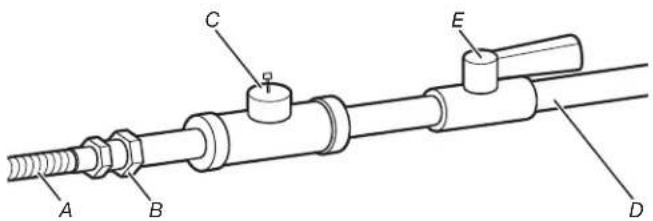
text_image
Technical diagram of a mechanical assembly with labeled components A, B, C, D, and EA. 3/8" fl exible gas connector
B. 3/8" pipe to fl are adapter fi tting
C. 1/8" NPT minimum plugged tapping
D. 1/2" NPT gas supply line
E. Gas shutoff valve
GAS SUPPLY CONNECTION REQUIREMENTS
Use an elbow and a 3/8" flare x 3/8" NPT adapter fitting between the fl exible gas connector and the dryer gas pipe, as needed, to avoid kinking.
■Use only pipe-joint compound. Do not use TEFLON ^® tape.
This dryer must be connected to the gas supply line with a listed fl exible gas connector that complies with the standard for connectors for gas appliances, ANSI Z21.24 or CSA 6.10.
BURNER INPUT REQUIREMENTS
Elevations above 2,000 ft. (610 m):
■ When installed above 2,000 ft. (610 m), a 4% reduction of the burner Btu rating shown on the model/serial number plate is required for each 1,000 ft. (305 m) increase in elevation.
Gas supply pressure testing
■The dryer must be disconnected from the gas supply piping system during pressure testing at pressures greater than 1/2 psi.
Dryer gas pipe
■The gas pipe that comes out through the rear of your dryer has a 3/8" male pipe thread.
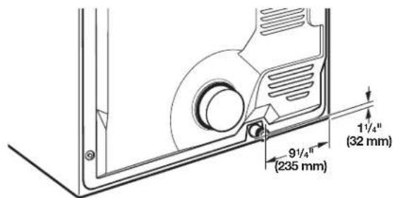
text_image
9½" (235 mm) 1½" (32 mm)3/8" NPT dryer gas pipe
INSTALL LEVELING LEGS
WARNING
Excessive Weight Hazard
Use two or more people to move and install dryer.
Failure to do so can result in back or other injury.
1. Prepare dryer for leveling legs
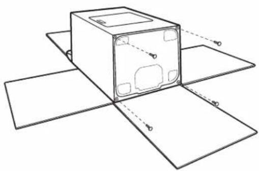
natural_image
Diagram of a device with labeled components and alignment lines (no text or symbols)To avoid damaging floor, use a large, flat at piece of cardboard from dryer carton; place under entire back edge of dryer. Firmly grasp dryer body (not console panel) and gently lay dryer down on cardboard.
2. Screw in leveling legs
or
natural_image
Illustration of three cylindrical mechanical components with threaded ends (no text or symbols)Using a wrench and tape measure, screw leveling legs into leg holes until bottom of foot is approximately 1/2" (13 mm) from bottom of dryer (so that the dryer height matches that of the accompanying washer).
Now stand the dryer on its feet. Slide the dryer until it is close to its final location. Leave enough room to connect the exhaust vent.
For mobile home use
Gas dryers must be securely fastened to the floor.
Mobile home installations require a Mobile Home Installation Hold-down Kit. For ordering information, please reference the "Use and Care Guide."
MAKE ELECTRICAL CONNECTION – U.S.A. ONLY (EFFECTUER LE RACCORDEMENT ÉLECTRIQUE – ÉTATS-UNIS SEULEMENT)
Power Supply Cord
WARNING

Fire Hazard
Use a new UL listed 30 amp power supply cord.
Use a UL listed strain relief.
Disconnect power before making electrical connections.
Connect neutral wire (white or center wire) to center terminal (silver).
Ground wire (green or bare wire) must be connected to green ground connector.
Connect remaining 2 supply wires to remaining 2 terminals (gold).
Securely tighten all electrical connections.
Failure to do so can result in death, fire, or electrical shock.
Direct Wire
WARNING

Fire Hazard
Use 10 gauge copper wire.
Use a UL listed strain relief.
Disconnect power before making electrical connections.
Connect neutral wire (white or center wire) to center terminal (silver).
Ground wire (green or bare wire) must be connected to green ground connector.
Connect remaining 2 supply wires to remaining 2 terminals (gold).
Securely tighten all electrical connections.
Failure to do so can result in death, fire, or electrical shock.
ELECTRICAL CONNECTION OPTIONS
1. Choose electrical connection type

Power supply cord 4-wire receptacle (NEMA Type 14-30R): Go to steps 1-2 on page 12 for power supply cord strain relief; then steps 3-6 for 4-wire Power Supply Cord Connection section. Then, go to Venting Requirements.
Power supply cord 3-wire receptacle (NEMA Type 10-30R): Go to steps 1-2 on page 12 for power supply cord strain relief; then steps 3-5 for 3-wire Power Supply Cord Connection section. Then go to Venting Requirements.
4-wire direct connection: Go to steps 1-2 on page 13 for direct wire strain relief; then steps 3-8 for 4-wire Direct Wire Connection section. Then go to Venting Requirements.
3-wire direct connection: Go to steps 1-2 on page 13 for direct wire strain relief; then steps 3-7 for 3-wire Direct Wire Connection section. Then go to Venting Requirements.
NOTE: If local codes do not permit connection of a cabinet-ground conductor to neutral wire, go to "Optional 3-wire Connection" section. This connection may be used with either a power supply cord or a direct wire connection.
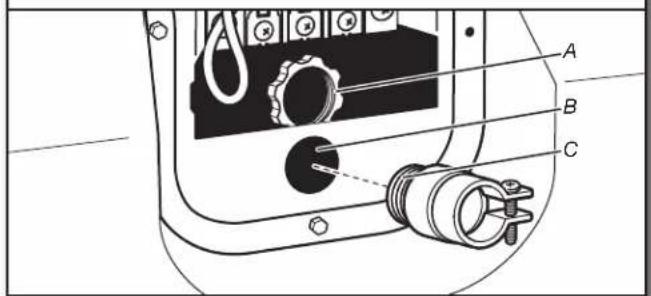
2. Remove terminal block cover
text_image
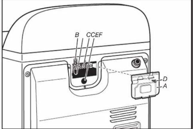
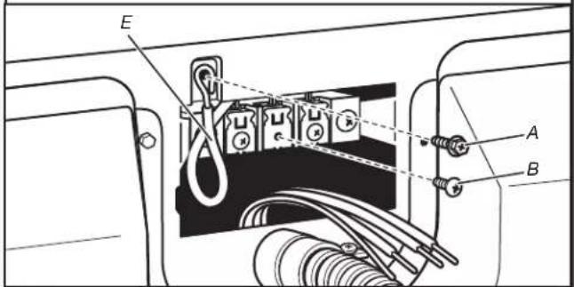
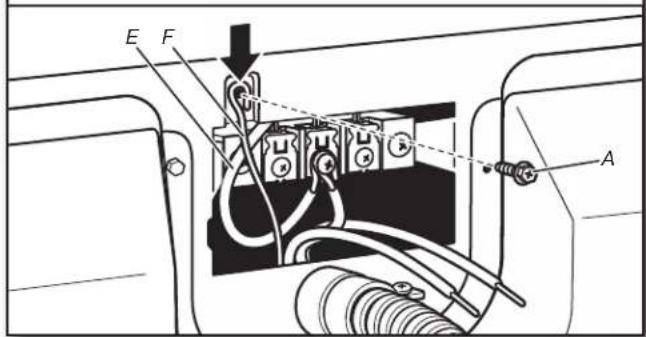
B CCEF D ABefore you start, disconnect power. Remove hold-down screw (D) and terminal block cover (A).
A. Terminal block cover
B. External ground conductor screw
C. Center terminal block screw
D. Hold-down screw
E. Neutral ground wire
F. Hole below terminal block cover
POWER SUPPLY CORD CONNECTION
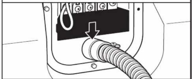
Power supply cord strain relief
- Attach power supply cord strain relief
text_image
A B C DRemove the screws from a 3/4" (19 mm) UL listed strain relief (UL marking on strain relief). Put the tabs of the two clamp sections (C) into the hole (B) below the terminal block opening so that one tab is pointing up (A) and the other is pointing down (D), and hold in place. Tighten strain relief screws just enough to hold the two clamp sections (C) together.
- Attach power supply cord to strain relief
natural_image
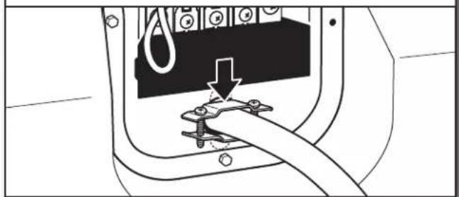
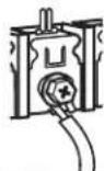
Diagram of a cable being inserted into an electrical socket (no text or symbols visible)Put power supply cord through the strain relief. Be sure that the wire insulation on the power supply cord is inside the strain relief. The strain relief should have a tight fit with the dryer cabinet and be in a horizontal position. Do not further tighten strain relief screws at this point.
For 3-wire Power Supply Cord Connection, continue to step 3 on page 13.
For 4-wire Power Supply Cord Connection, continue to step 3 on this page.
4-wire Power Supply Cord Connection
IMPORTANT: A 4-wire connection is required for mobile homes and where local codes do not permit the use of 3-wire connections.
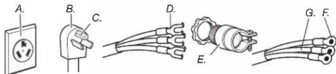
text_image
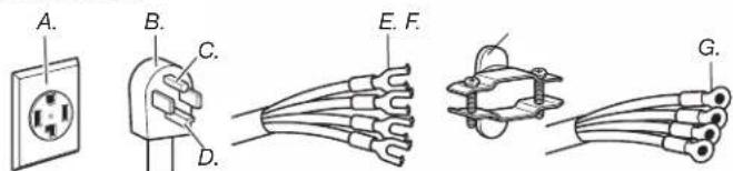
A. B. C. D. E. F. G.A. 4-wire receptacle (NEMA type 14-30R)
B. 4-prong plug
C. Ground prong
D. Neutral prong
E. Spade terminals with upturned ends
F. 3/4" (19 mm) UL listed strain relief
G. Ring terminals
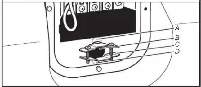
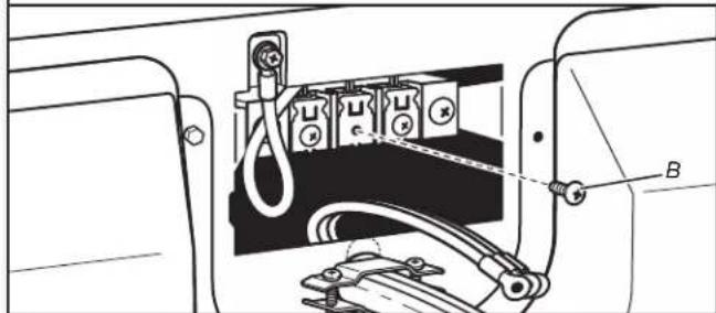
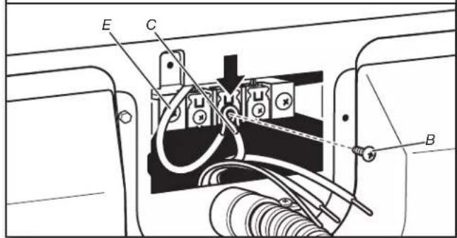
- Prepare to connect neutral ground wire and neutral wire
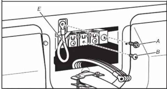
text_image
E A BRemove center terminal block screw (B). Remove neutral ground wire (E) from external ground conductor screw (A).
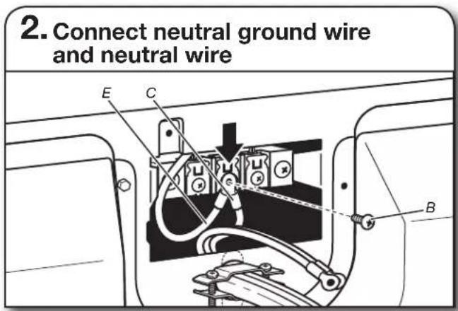
- Connect neutral ground wire and neutral wire
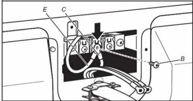
text_image
E C BConnect neutral ground wire (E) and neutral wire (white or center) (C) of power supply cord under center terminal block screw (B). Tighten screw.
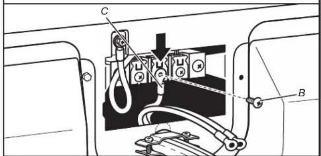
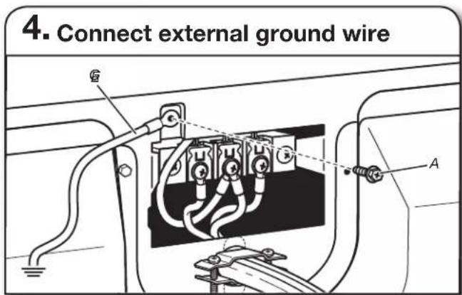
- Connect ground wire
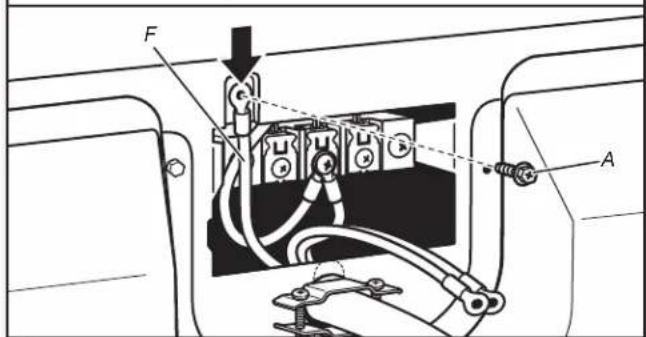
text_image
Technical diagram of an electrical switch assembly with labeled components A and FConnect ground wire (F) (green or bare) of power supply cord to external ground conductor screw (A). Tighten screw.
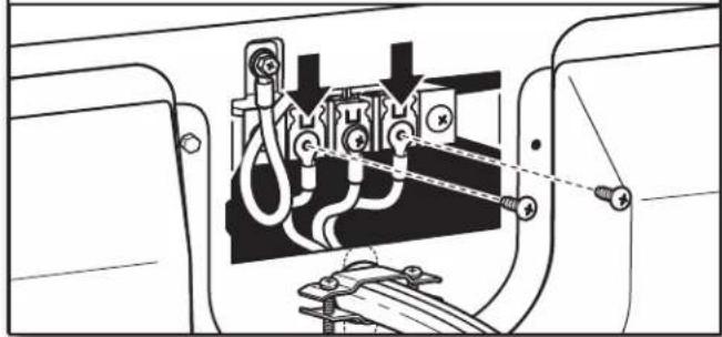
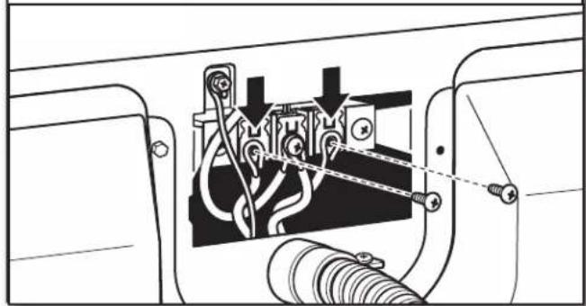
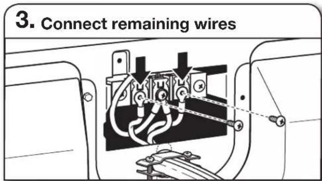
6. Connect remaining wires
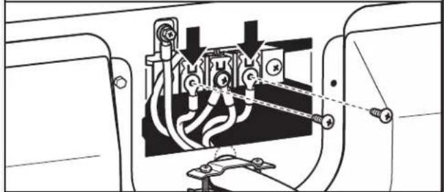
natural_image
Technical diagram of an electrical switchgear assembly with no visible text or symbolsConnect remaining wires to outer terminal block screws. Tighten screws. Finally, reinstall terminal block cover. Secure cover with hold-down screw. Now, go to Venting Requirements.
3-wire Power Supply Cord Connection Use where local codes permit connecting cabinet-ground conductor to neutral wire.
text_image
A. B. C. D. E. G. F.A. 3-wire receptacle (NEMA type 10-30R)
B. 3-wire plug
C. Neutral prong
D. Spade terminals with upturned ends
E. 3/4" (19 mm) UL listed strain relief
F. Ring terminals
G. Neutral (white or center wire)
3. Remove center screw
natural_image
Technical diagram of an electrical switch assembly with labeled component B (no text or symbols present)Remove center terminal block screw (B).
4. Connect neutral wire
text_image
Technical diagram showing electrical switch connections with labeled components A and B, and component CConnect neutral wire (white or center) (C) of power supply cord to center terminal block screw (B). Tighten screw.
5. Connect remaining wires
natural_image
Technical diagram of a mechanical assembly with no visible text or symbolsConnect remaining wires to outer terminal block screws. Tighten screws. Finally, reinstall terminal block cover. Secure cover with hold-down screw. Now, go to Venting Requirements.
DIRECT WIRE CONNECTION Direct wire strain relief
1. Attach direct wire strain relief
text_image
Technical diagram of a mechanical device with labeled parts A, B, and CUnscrew the removable conduit connector (A) and any screws from a 3/4" (19 mm) UL listed strain relief (UL marking on strain relief). Put the threaded section of the strain relief through the hole (B) below the terminal block opening. Reaching inside the terminal block opening, screw the removable conduit connector onto the strain relief threads (C).
2. Attach direct wire cable to strain relief
natural_image
Diagram of a cable connector with a valve and plug, showing internal wiring (no text or symbols)Put direct wire cable through the strain relief. The strain relief should have a tight fit with the dryer cabinet and be in a horizontal position. Tighten strain relief screws.
For 3-wire Direct Wire Connection, continue to step 3 on page 15.
For 4-wire Direct Wire Connection, continue to step 3 on the next page.
4-wire Direct Wire Connection
IMPORTANT: A 4-wire connection is required for mobile homes and where local codes do not permit 3-wire connections.
3. Prepare your 4-wire cable for direct connection
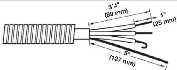
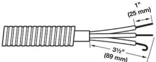
text_image
3½" (89 mm) 1" (25 mm) 5" (127 mm)Direct wire cable must have 5 ft. (1.52 m) of extra length so dryer may be moved if needed.
Strip 5" (127 mm) of outer covering from end of cable, leaving bare ground wire at 5" (127 mm). Cut 1 ^1/2 " (38 mm) from remaining 3 wires. Strip insulation back 1" (25 mm). Shape ends of wires into hooks.
4. Connect wires to terminal block
To connect wires to terminal block, place hooked end of wire under terminal block screw, facing to the right, squeeze hooked end together, and tighten screw.
5. Prepare to connect neutral ground wire and neutral wire
text_image
E A BRemove center terminal block screw (B). Remove neutral ground wire (E) from external ground conductor screw (A).
6. Connect neutral ground wire and neutral wire
text_image
E C BConnect neutral ground wire (E) and place hooked end (hook facing right) of neutral wire (white/center wire) (C) of direct wire cable under center screw of terminal block (B). Squeeze hooked ends together and tighten screw.
7. Connect ground wire
text_image
E F AConnect ground wire (green or bare) (F) of direct wire cable to external ground conductor screw (A). Tighten screw.
8. Connect remaining wires
natural_image
Technical diagram of an electrical switch mechanism inside a motor (no text or labels)Place hooked ends of remaining direct wire cable wires under outer terminal block screws (hooks facing right). Squeeze hooked ends together and tighten screws. Finally, reinstall terminal block cover. Now, go to Venting Requirements.
3-wire Direct Wire Connection
Use where local codes permit connecting cabinet-ground conductor to neutral wire.
3. Prepare your 3-wire cable for direct connection
text_image
1" (25 mm) 3½" (89 mm)Direct wire cable must have 5 ft. (1.52 m) of extra length so dryer may be moved if needed.
Strip 3 ^1/2 " (89 mm) of outer covering from end of cable. Strip insulation back 1" (25 mm). If using 3-wire cable with ground wire, cut bare wire even with outer covering. Shape wire ends into hooks.
4. Connect wires to terminal block
To connect wires to terminal block, place hooked end of wire under terminal block screw, facing to the right, squeeze hooked end together, and tighten screw.
5. Remove center screw
natural_image
Technical diagram of an electrical switch assembly with labeled component B (no text or symbols present)Remove center terminal block screw (B).
6. Connect neutral wire
text_image
Technical diagram of a mechanical or electrical component with labeled parts C and B, showing connections and assembly lines.Place hooked end of neutral wire (white or center) (C) of direct wire cable under center terminal block screw (B). Squeeze hooked end together. Tighten screw.
7. Connect remaining wires
natural_image
Technical diagram of a mechanical or electrical component with no visible text, numbers, or symbolsPlace hooked ends of remaining direct wire cable wires under outer terminal block screws (hooks facing right). Squeeze hooked ends together and tighten screws. Finally, reinsert tab of terminal block cover into slot of dryer rear panel. Secure cover with hold-down screw. Now, go to Venting Requirements.
Optional 3-wire Connection
You must verify with a qualified electrician that this grounding method is acceptable before connecting.
1. Prepare to connect neutral ground wire and neutral wire
text_image
E A BRemove center terminal block screw (B). Remove neutral ground wire (E) from external ground conductor screw (A).
text_image
2. Connect neutral ground wire and neutral wire E C BConnect neutral ground wire (E) and neutral wire (white or center wire) (C) of power supply cord or cable under center terminal block screw (B). Tighten screw.
text_image
3. Connect remaining wiresPlace hooked ends of remaining wires under outer terminal block screws (hooks facing right). Tighten screws.
text_image
4. Connect external ground wire G AConnect a separate copper ground wire (G) from the external ground conductor screw (A) to an adequate ground. Finally, reinsert tab of terminal block cover into slot of dryer rear panel. Secure cover with hold-down screw. Now, go to Venting Requirements.
MAKE GAS CONNECTION
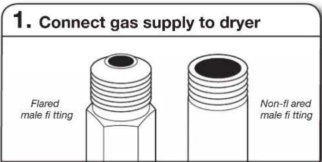
text_image
1. Connect gas supply to dryer Flared male fi tting Non-fl ared male fi ttingRemove red cap from gas pipe. Using a wrench to tighten, connect gas supply to dryer. Use pipe-joint compound on threads of all non-fl ared male fi ttings. If fl exible metal tubing is used, be sure there are no kinks.
NOTE: For LP gas connections, you must use pipe-joint compound resistant to action of LP gas. Do not use TEFLON® tape.
text_image
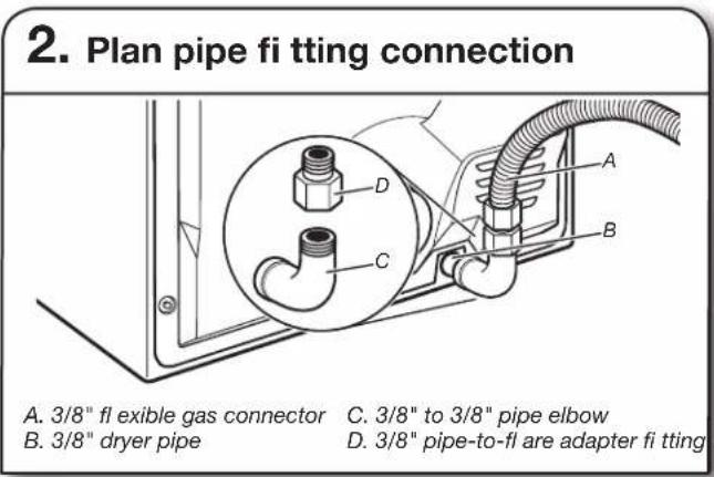
2. Plan pipe fi tting connection A. 3/8" fl exible gas connector C. 3/8" to 3/8" pipe elbow B. 3/8" dryer pipe D. 3/8" pipe-to-fi are adapter fi ttingA combination of pipe fittings must be used to connect dryer to existing gas line. A recommended connection is shown. Your connection may be different, according to supply line type, size, and location.
text_image
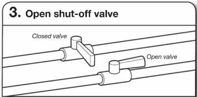
3. Open shut-off valve Closed valve Open valveOpen shut-off valve in supply line; valve is open when handle is parallel to gas pipe. Then, test all connections by brushing on an approved noncorrosive leak-detection solution. Bubbles will show a leak. Correct any leaks found.
VENTING
Venting Requirements
WARNING

Fire Hazard
Use a heavy metal vent.
Do not use a plastic vent.
Do not use a metal foil vent.
Failure to follow these instructions can result in death or fire.
WARNING: To reduce the risk of fire, this dryer MUST BE EXHAUSTED OUTDOORS.
IMPORTANT: Observe all governing codes and ordinances.
Dryer exhaust must not be connected into any gas vent, chimney, wall, ceiling, attic, crawlspace, or a concealed space of a building. Only rigid or flexible metal vent shall be used for exhausting.
text_image
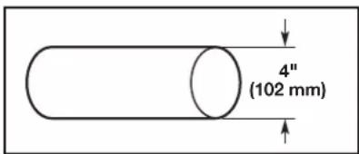
4" (102 mm)4" (102 mm) heavy metal exhaust vent
■Only a 4" (102 mm) heavy metal exhaust vent and clamps may be used.
■Do not use plastic or metal foil vent.
Rigid metal vent:
■Recommended for best drying performance and to avoid crushing and kinking.
Flexible metal vent: (Acceptable only if accessible to clean)
■Must be fully extended and supported in final dryer location.
■Remove excess to avoid sagging and kinking that may result in reduced airflow and poor performance.
■Do not install in enclosed walls, ceilings, or floors.
■The total length should not exceed 7^3/_4 ft. (2.4 m).
NOTE: If using an existing vent system, clean lint from entire length of the system and make sure exhaust hood is not plugged with lint. Replace plastic or metal foil vents with rigid metal or flexible metal vents. Review “Vent System Chart” and, if necessary, modify existing vent system to achieve best drying performance.
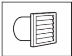
Exhaust hoods:
■Must be at least 12" (305 mm) from ground or any object that may obstruct exhaust (such as flowers, rocks, bushes, or snow).
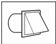
Recommended Styles:
natural_image
Simple line drawing of a vent with airflow or ventilation slots (no text or symbols)Louvered hood Box hood
natural_image
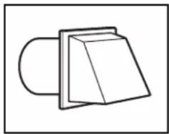
Simple line drawing of a mechanical component with a rectangular housing and rounded base (no text or symbols)Acceptable Style:
natural_image
Simple line drawing of a mechanical component or bracket (no text or symbols)Angled hood
Elbows:
■45° elbows provide better airflow than 90° elbows.
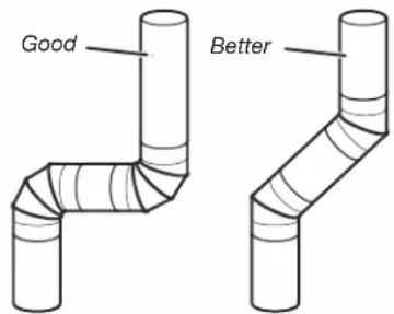
text_image
Good BetterClamps:
■Use clamps to seal all joints.
■Exhaust vent must not be connected or secured with screws or other fastening devices that extend into interior of duct and catch lint. Do not use duct tape.
natural_image
Simple diagram showing a circular object with an arrow pointing left and a ring on the right (no text or symbols)
natural_image
Pure mechanical diagram showing a rotating component with an arrow indicating direction, no text or symbols presentImproper venting can cause moisture and lint to collect indoors, which may result in:
■ Moisture damage to woodwork, furniture, paint, wallpaper, carpets, etc.
■ Housecleaning problems and health problems.
Plan Vent System
Recommended exhaust installations
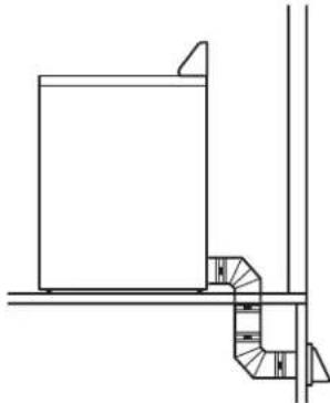
Typical installations vent the dryer from the rear of the dryer. Other installations are possible.
text_image
A B C D E F G B E HA. Dryer
E. Clamps
B. Elbow
F. Rigid metal or flexible metal vent
C. Wall
G. Vent length necessary to connect elbows
D. Exhaust hood
H. Exhaust outlet
natural_image
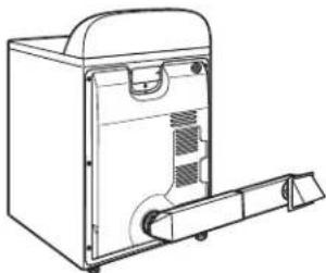
Line drawing of a brick wall-mounted electrical cabinet with a piping fixture (no text or symbols)Standard rear offset exhaust installation
Alternate installations for close clearances
Venting systems come in many varieties. Select the type best for your installation. Two close-clearance installations are shown. Refer to the manufacturer's instructions.
natural_image
Diagram of a portable air conditioner unit with coiled tubing and ventilation slots (no text or symbols)Over-The-Top installation (also available with one offset elbow)
natural_image
Line drawing of a portable refrigerator with handle and ventilation slots (no text or symbols)Periscope installation
NOTE: The following kits for close clearance alternate installations are available for purchase.
Venting Kits
For more information, call 1-866-698-2538 (Whirlpool) or 1-800-344-1274 (Maytag), or visit us at
www.applianceaccessories.com (Whirlpool) or www.maytag.com (Maytag).
In Canada, call 1-800-688-2002 (Whirlpool and Maytag) or visit us at www.whirlpoolparts.ca (Whirlpool) or www.maytag.ca (Maytag).
| Part Number Descriptions |
| 8171587RP 0"-5" Metal vent periscope |
| 4396037RP 0"-18" Metal vent periscope |
| 4396011RP 18"-29" Metal vent periscope |
| 4396014 29"-50" Metal vent periscope |
| 4392892 In-Wall metal DuraVentTM Periscope |
| 4396028 Sure ConnectTM venting kit(over-the-top installation) |
| 4396009RP 5' Universal connect vent, flexible dryer venting |
| 4396010RP 6' SecureConnectTM vent, flexible dryer venting |
| 4396013RB Dryer vent installer's kit |
| 4396033RP 5' flexible dryer venting with clamps |
| 4396727RP 8' flexible dryer venting with clamps |
| 4396004 Dryer offset elbow |
| 4396005 Wall offset elbow |
| 4396006RW DuraSafeTM close elbow |
| 4396007RW Through-the-wall vent cap |
| 4396008RP 4" steel dryer venting clamps - 2 pack |
| 8212662 Flush mounting louvered vent hood 4" |
Special provisions for mobile home installations:
The exhaust vent must be securely fastened to a noncombustible portion of the mobile home structure and must not terminate beneath the mobile home. Terminate the exhaust vent outside.
natural_image
Pure architectural line drawing of a staircase and adjacent building (no text or symbols)Determine vent path:
■ Select route that will provide straightest and most direct path outdoors.
■Plan installation to use fewest number of elbows and turns.
■When using elbows or making turns, allow as much room as possible.
■Bend vent gradually to avoid kinking.
■Use as few 90° turns as possible.
Determine vent length and elbows needed for best drying performance:
■Use following "Vent System Chart" to determine type of vent material and hood combinations acceptable to use.
NOTE: Do not use vent runs longer than those specified in "Vent System Chart." Exhaust systems longer than those specified will:
■Shorten life of dryer.
■Reduce performance, resulting in longer drying times and increased energy usage.
The "Vent System Chart" provides venting requirements that will help achieve best drying performance.
| Vent System Chart | |||
| Number of 90° turns or elbows | Type of vent | Box/louvered hoods | Angled hoods |
| 0 Rigid metal 64 ft. (20 m) 58 ft. (17.7 m) | |||
| 1 Rigid metal 54 ft. (16.5 m) 48 ft. (14.6 m) | |||
| 2 Rigid metal 44 ft. (13.4 m) 38 ft. (11.6 m) | |||
| 3 Rigid metal 35 ft. (10.7 m) 29 ft. (8.8 m) | |||
| 4 Rigid metal 27 ft. (8.2 m) 21 ft. (6.4 m) | |||
| Vent System Chart(29" Wide Long Vent WED/WGD4870and WED/WGD4975 Models Only) | ||
| Number of90° turnsor elbows | Typeof vent | Box/louveredor angled hoods |
| 0 Rigid metal 160 ft. (48.8 m) | ||
| 1 Rigid metal 150 ft. (45.7 m) | ||
| 2 Rigid metal 140 ft. (42.7 m) | ||
| 3 Rigid metal 130 ft. (39.6 m) | ||
| 4 Rigid metal 120 ft. (36.6 m) | ||
| 5 Rigid metal 110 ft. (33.5 m) | ||
INSTALL VENT SYSTEM
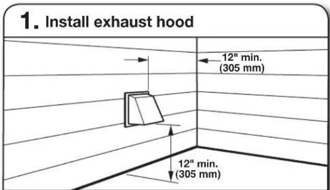
text_image
1. Install exhaust hood 12" min. (305 mm) 12" min. (305 mm)Install exhaust hood and use caulking compound to seal exterior wall opening around exhaust hood.
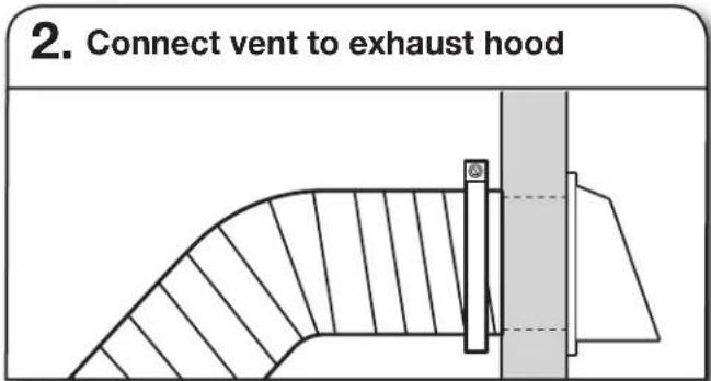
text_image
2. Connect vent to exhaust hoodVent must fit over the exhaust hood. Secure vent to exhaust hood with 4" (102 mm) clamp. Run vent to dryer location using straightest path possible. Avoid 90° turns. Use clamps to seal all joints. Do not use duct tape, screws, or other fastening devices that extend into interior of vent to secure vent, because they can catch lint.
CONNECT INLET HOSES
(Steam Models Only)
For non-steam models, skip to "Connect Vent."
The dryer must be connected to the cold water faucet using the new inlet hoses. Do not use old hoses.
1. Turn cold water off, remove and replace rubber washer

natural_image
Pure electrical circuit lines without any symbolsTurn cold water faucet off and remove washer inlet hose. Remove old rubber washer from inlet hose and replace with new rubber washer.
2. Attach short hose and "Y" connector
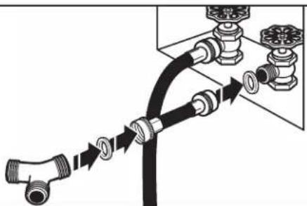
natural_image
Diagram of a pipe connection with fittings and valves, showing fluid flow direction (no text or labels)Attach 2 ft (0.6 m) inlet hose to cold water faucet. Screw on coupling by hand until it is seated on faucet. Then attach "Y" connector to end of the 2 ft (0.6 m) inlet hose. Screw on coupling by hand until it is seated on "Y" connector.
3. Tighten couplings
natural_image
Mechanical assembly diagram showing a hand operating a valve with hoses and tubing (no text or symbols)Using pliers, tighten the couplings with additional two-thirds turn.
NOTE: Do not overtighten. Damage to the coupling can result.
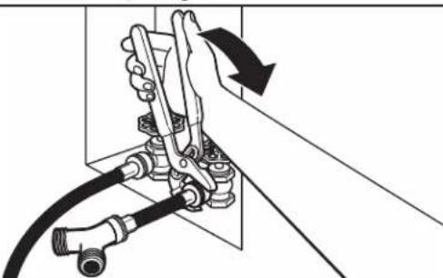
4. Attach long hose to "Y" connector and tighten couplings
natural_image
Pure electrical circuit lines without any symbolsAttach dryer 5 ft (1.5 m) inlet hose ends to the "Y" connector. Attach washer cold inlet hose to other side of "Y" connector. Screw on coupling by hand until it is seated on connector. Using pliers, tighten the couplings an additional two-thirds turn.
NOTE: Do not overtighten. Damage to the coupling can result.
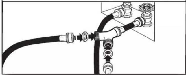
5. Attach long hose to dryer fi ll valve and tighten coupling
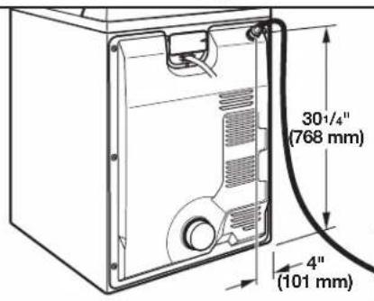
text_image
30½/4" (768 mm) 4" (101 mm)Attach other end of long hose to fi ll valve at top of dryer back panel. Screw on coupling by hand until it is seated on fi ll valve connector. Using pliers, tighten the coupling an additional two-thirds turn.
NOTE: Do not overtighten. Damage to the coupling can result.
natural_image
Diagram of a curved pipe with a rotating arrow indicating flow direction (no text or symbols)6. Turn on cold water faucet
natural_image
Pure diagram of a pipe connection with valves and fittings, no text or symbols presentCheck that the water faucet is turned on.
text_image
7. Check for leaksCheck for leaks around "Y" connector, faucet, and hoses.
CONNECT VENT
text_image
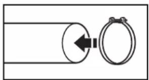
1. Connect vent to exhaust outletUsing a 4" (102 mm) clamp, connect vent to exhaust outlet in dryer. If connecting to existing vent, make sure vent is clean. Dryer vent must fit over dryer exhaust outlet and inside exhaust hood. Check that vent is secured to exhaust hood with a 4" (102 mm) clamp.

text_image
2. Move dryer to fi nal locationMove dryer to fi nal location. Avoid crushing or kinking vent.
LEVEL DRYER
text_image
1. Level dryerCheck levelness of dryer from side to side. Repeat from front to back.
NOTE: The dryer must be level for the moisture sensing system to operate correctly.
Not Level
natural_image
Simple geometric diagram with a circle containing three shaded rectangular regions and a small semicircle inside (no text or symbols)LEVEL
Not Level
text_image
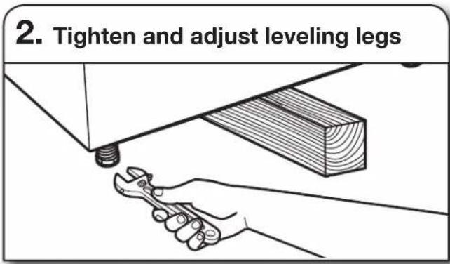
2. Tighten and adjust leveling legsIf dryer is not level or the same height as the washer, prop up using a wood block. Use wrench to adjust legs up or down, and check again for levelness. Once legs are level, make sure all four legs are snug against the floor before tightening them.
COMPLETE INSTALLATION CHECKLIST
☐ Check that all parts are now installed. If there is an extra part, go back through steps to see what was skipped.
☐ Check that you have all of your tools.
☐ Dispose of/recycle all packaging materials.
☐ Check dryer's final location. Be sure vent is not crushed or kinked.
☐ Check that dryer is level. See "Level Dryer."
Remove film on console and any tape remaining on dryer.
☐ Wipe dryer drum interior thoroughly with a damp cloth to remove any dust.
Read "Dryer Use" in your "Use and Care Guide."
☐ Set the dryer on a full heat cycle (not an air cycle) for 20 minutes and start the dryer.
Be sure the water faucets are on.
☐ Check for leaks around "Y" connector, faucet, and hoses.
☐ If you live in a hard water area, use of a water softener is recommended to control the buildup of scale through the water system in the dryer. Over time, the buildup of lime scale may clog different parts of the water system, which will reduce product performance. Excessive scale buildup may lead to the need for certain part replacement or repair.
If the dryer will not start, check the following:
■Dryer is plugged into a grounded 3-prong outlet.
■Electrical supply is connected.
■Household fuse is intact and tight, or circuit breaker has not tripped.
■Dryer door is closed.
☐ When the dryer has been running for 5 minutes, open the dryer door and feel for heat. If you feel heat, cancel cycle and close the door.
If you do not feel heat, turn the dryer off and check to see whether gas supply line shut-off valve is open.
■If the gas supply line shut-off valve is closed, open it, then repeat the 5-minute test as outlined above.
■If the gas supply line shut-off valve is open, contact a qualified technician.
NOTE: You may notice an odor when the dryer is first heated. This odor is common when the heating element is first used. The odor will go away.
REVERSE DOOR SWING (OPTIONAL)
NOTE: Magnetized screwdriver is helpful.
- Place towel on dryer
natural_image
Line drawing of a washing machine with a lid and front panel (no text or symbols)Place towel on top of dryer to avoid damaging the surface.
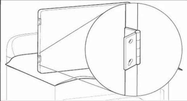
- Remove bottom screws
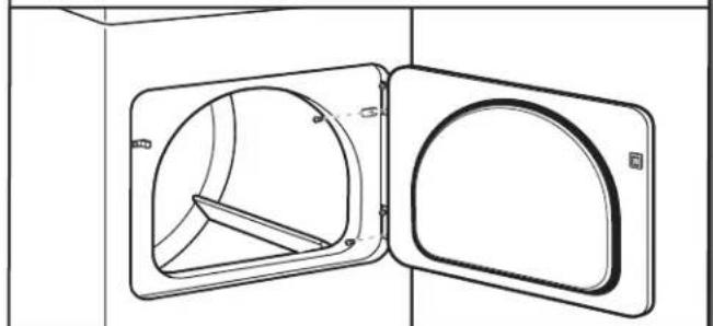
natural_image
Technical line drawing of a door opening with internal structural details (no text or symbols)Open dryer door. Remove bottom screws from dryer cabinet side of hinges. Loosen (do not remove) top screws from dryer cabinet side of hinges.
- Lift door off top screws
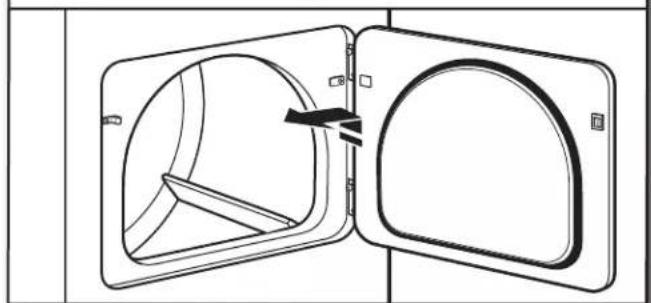
natural_image
Diagram of an open door with internal structural components, showing no text or symbolsLift door until top screws in dryer cabinet are in large part of hinge slot. Pull door forward off screws. Set door (handle side up) on top of dryer. Remove top screws from dryer cabinet.
text_image
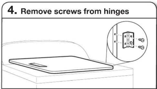
4. Remove screws from hingesRemove screws attaching hinges to door.
flowchart
graph TD
    A["Device 1"] --> B["Device 2"]
    B --> C["Device 3"]
    C --> D["Device 4"]
    D --> E["Device 5"]
    E --> F["Device 6"]
    F --> G["Device 7"]
    style A fill:#f9f,stroke:#333
    style B fill:#f9f,stroke:#333
    style C fill:#f9f,stroke:#333
    style D fill:#f9f,stroke:#333
    style E fill:#f9f,stroke:#333
    style F fill:#f9f,stroke:#333
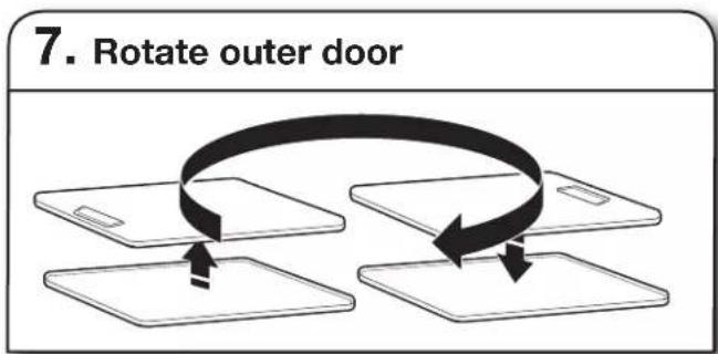
Rotate outer door 180° and set it back down on inner door. Reattach outer door panel to inner door panel so handle is on the side where hinges were just removed. Insert 4 door screws.
text_image
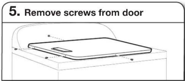
5. Remove screws from doorRemove screws at top, bottom, and side of door (4 screws) that hold the inner and outer door together. Holding door over towel on dryer, grasp sides of outer door and lift to separate it from inner door. Set outer door aside.
NOTE: Do not pry apart with putty knife or screwdriver. Do not pull on door seal or plastic door catches.
text_image
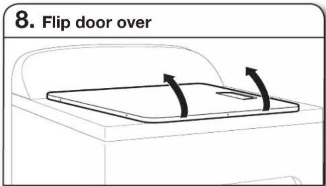
8. Flip door overFlip door over so handle side is down.
text_image
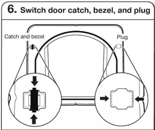
6. Switch door catch, bezel, and plug Catch and bezel PlugRemove the door catch, bezel, and plug from the inside of the inner door by squeezing and pulling/pushing them. Place the door catch, bezel, and plug on the sides opposite from where they were.
text_image
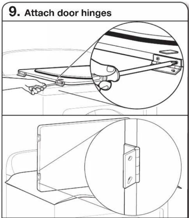
9. Attach door hingesReattach door hinges to dryer door so that the larger hole is at the bottom of the hinge.
text_image
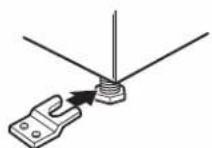
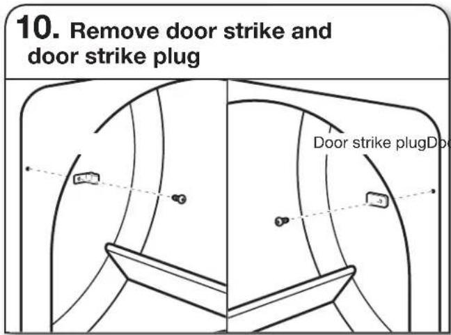
10. Remove door strike and door strike plug Door strike plugDpcRemove door strike and door strike plug from dryer cabinet. Insert the door strike into door strike plug hole and secure with screw. Insert door strike plug into original door strike hole and secure with screw.
text_image
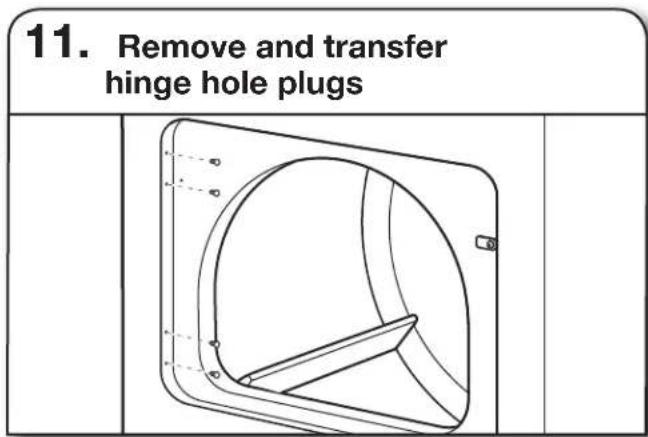
11. Remove and transfer hinge hole plugsUse a small, fl at-blade screwdriver to gently remove 4 hinge hole plugs on left side of dryer cabinet. Transfer plugs into hinge holes on opposite side of dryer cabinet.
text_image
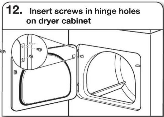
12. Insert screws in hinge holes on dryer cabinetNOTE: Two people may be needed to reinstall door. Insert screws into the bottom holes on left side of dryer cabinet. Tighten screws halfway. Position door so large end of door hinge slot is over screws. Slide door up so screws are in bottom of slots. Tighten screws. Insert and tighten top screws in hinges.
text_image
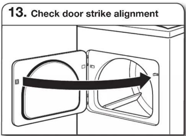
13. Check door strike alignmentClose door and check that door strike aligns with door catch. If it is needed, slide door catch left or right within slot to adjust alignment.
TROUBLESHOOTING
See the Use and Care Guide or visit our website and reference Frequently Asked Questions to possibly avoid the cost of a service call.
natural_image
Simple line drawing of a screwdriver (no text or symbols)
natural_image
Simple line drawing of a screwdriver (no text or symbols)natural_image
Simple line drawing of a screwdriver with a handle and end cap (no text or symbols)natural_image
Simple line drawing of a pair of pliers (no text or symbols)natural_image
Simple line drawing of a measuring tape (no text or symbols)Mètre-ruban
natural_image
Two interlocked rings with metal clips attached (no text or symbols)natural_image
Simple line drawing of a rectangular object with three circular holes, no text or symbols present.Niveau
natural_image
Line drawing of a pair of pliers (no text or symbols)Pince
natural_image
Line drawing of an adjustable wrench (no text or symbols)natural_image
Two line drawings of laboratory pipettes: a cylindrical tool and a syringe (no text or symbols)natural_image
Simple line drawing of a flat tool with a handle and central slot (no text or symbols)Couteau utilitaire
natural_image
Simple line drawing of a cylindrical object with a tapered end (no text or symbols)Couteau à mastic
natural_image
Line drawing of a pair of pliers with metal handles and a screw (no text or symbols)natural_image
Line drawing of an adjustable wrench (no text or symbols)natural_image
Line drawing of an adjustable wrench (no text or symbols)
natural_image
Simple line drawing of a jar with a lid and handle (no text or symbols)natural_image
Two technical illustrations of bolted components, one showing a hexagonal nut and the other showing multiple threaded bolts (no text or symbols present)natural_image
Three technical illustrations of pipe fittings: a threaded pipe fitting, a flexible hose with connectors, and a washer (no text or symbols)natural_image
Coiled black rubber hose with two end fittings (no text or symbols visible)text_image
29" (737 mm) 407/8" (1038 mm) 1/2" (13 mm)text_image
Technical diagram of a mechanical assembly with labeled components A, B, C, D, and Enatural_image
Diagram of a device with a central box and surrounding planes, no text or symbols presentnatural_image
Illustration of three cylindrical mechanical components with threaded ends (no text or symbols)text_image
Technical diagram showing pipe connection components with labeled parts A, C, and DA. Raccord fl exible de gaz de 3/8"
text_image
4" (102 mm)natural_image
Simple line drawing of a vent or airflow device with a curved handle and rectangular frame (no text or symbols)
natural_image
Simple line drawing of a 3D object resembling a mechanical part or bracket (no text or symbols)natural_image
Simple line drawing of a mechanical component or bracket (no text or symbols)Clapet incliné
Coudes :
natural_image
Simple line drawing of two circular objects with a directional arrow, no text or symbols present
natural_image
Simple line drawing of a utility box mounted on a brick wall, no text or symbols presentnatural_image
Diagram of a portable air conditioner unit with coiled tubing and a close-up inset showing internal components (no text or symbols)natural_image
Line drawing of a portable kitchen appliance with lid, ventilation slots, and handle (no text or symbols)natural_image
Pure architectural line drawing of a staircase and adjacent building (no text or symbols)natural_image
Mechanical assembly diagram showing a hand operating a valve with hoses and a rotating arrow (no text or symbols)natural_image
Pure diagram of a cable being inserted into a connector, no text or symbols presentnatural_image
Diagram of a car exhaust pipe with airflow direction arrow (no text or labels)natural_image
Pure electrical circuit lines without any symbolsnatural_image
Three-panel illustration showing pipe fittings and water droplets during installation (no text or symbols)natural_image
Technical line drawing of a mechanical component with hoses and a central knob (no text or symbols)natural_image
Simple line drawing of a washing machine with a door and arrow indicating left motion (no text or symbols)natural_image
Line drawing of a kitchen appliance with a lid and handle (no text or symbols)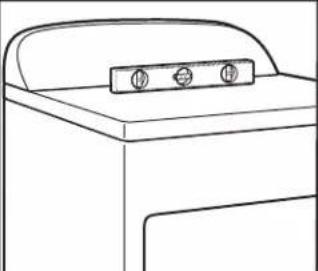
natural_image
Line drawing of a washing machine with a lid and two buttons (no text or symbols)natural_image
Line drawing of a hand using a wrench to lift a wooden block (no text or symbols)natural_image
Line drawing of a laptop with a screen and lid, shown in perspective view (no text or symbols)natural_image
Diagram of a device with two curved arrows indicating rotation or movement (no text or symbols)natural_image
Diagram showing a hand holding a tool interacting with a car's steering wheel, with an inset close-up of the handle (no text or symbols present)