USER MANUAL DAS180EAQHWDB DANBY
SPLIT AIR CONDITIONER Owner's Manual. 1-24
SAFETY PRECAUTIONS
Incorrect installation due to ignoring instructions can cause serious damage or injury.
- Installation must be performed by a certified HVAC technician. Defective installation can cause water leakage, electrical shock or fire.
- In North America, installation must be performed in accordance with the requirement of NEC and CEC by authorized personnel only.
- Contact an HVAC technician or the sales agent for information on repair or maintenance of this appliance.
- When connecting refrigerant piping, do not let substances or gases other than the specified refrigerant enter the lines as this will lower the unit's capacity and can cause abnormally high pressure in the refrigeration system, which can lead to explosion or injury.
- Check that air cannot enter the refrigerant system and check for refrigerant leaks when moving the appliance.
- Only use the included accessories, parts and specified parts for installation. Using non-standard parts can cause water leakage, electrical shock, fire and can cause the unit to fail.
- Install the appliance in a firm location that can support the unit's weight. If the chosen location cannot support the appliance's weight, or if the installation is not completed properly, the appliance may fall and cause serious injury or damage.
- Do not climb on or place objects on the outdoor appliance.
-
Do not touch the appliance when barefoot or if parts of the body are wet.
-
For all electrical work, follow all local and national wiring standards and regulations and this manual. You must use an independent circuit and single outlet to supply power. Do not connect other appliances to the same outlet. Insuffcient electrical capacity or defects in electrical work can cause electrical shock or fire.
- For all electrical work, use all specified cables. Connect cables tightly and clamp them securely to prevent external forces from damaging the terminal. Improper electrical connections can overheat and cause electrical shock or fire.
- All wiring must be correctly arranged to ensure that the control board can close properly. If the control board cover is not closed properly, it can lead to corrosion and cause the connection points on the terminal to overheat, catch fire or cause electrical shock.
- The user must protect the indoor appliance with a fuse of suitable capacity for the maximum input current or with another overload protection device.
- Ensure that the mains voltage corresponds to the value stamped on the rating plate. Keep the switch or power plug clean. Insert the power plug correctly and fi rmly into the socket thereby avoiding the risk of electric shock or fi re from insufficient cients contact.
- Check that the socket is suitable for the plug. If it is not, have the plug changed.
- This appliance must be fitted with means for disconnection from the supply mains having a contact separation in all poles that provide full disconnection under over voltage category III conditions and these means must be incorporated in the fi xed wiring in accordance with wiring rules.

- Before accessing the terminals all the power circuits must be disconnected from the power supply.
- In certain functional environments, such as kitchens, server rooms, etc, the use of specially designed air conditioning units is highly recommended.
- This appliance is not intended for use by persons (including children) whose physical, sensory or metal capabilities may be different or reduced, or who lack experience or knowledge, unless such persons receive supervision or training to operate the appliance by a person responsible for their safety.
- Do not install the appliance in a location that may be exposed to combustible gas leaks. If combustible gas accumulates around the appliance, it may cause fire.
- Do not install the appliance within 20 inches of a source of infl ammable substances or pressurized containers.
- If the appliance is used in an area without proper ventilation, precautions must be taken to prevent any leaks of refrigerant gas from remaining in the environment and creating a danger of fire.
- Do not operate this appliance in a wet room such as a bathroom or laundry room. Too much exposure to water can cause electrical components to short circuit.
- The appliance must be properly grounded or electric shock can occur.
- Install drainage piping according to the instructions in this manual. Improper drainage may cause water damage.
-
Carry out a test cycle after installing the appliance and record the operating data.
-
If the appliance produces smoke or there is a smell of burning immediately cut off the power and contact an authorized service center.
- Cleaning and maintenance must be carried out by specialized technical personnel. Disconnect the appliance from the main electricity supply before performing any cleaning or maintenance.
- Always use the appliance with the air fi liter installed. The use of the appliance without the air fi liter could cause an excessive accumulation of dust in the inner parts of the device with possible subsequent failures.
- This appliance has been made for air conditioning domestic environments and must not be used for any other purpose. These instructions are not intended to cover every possible condition and situation. Common sense and caution are recommended for installation, operation and maintenance.
NOTE ABOUT FLUORINATED GASES
- This appliance contains fluorinated gasses. For specific information on the type and amount of gas, refer to the relevant label on the appliance itself.
- Installation, service, maintenance and repair of this appliance must be performed by a certifi ed HVAC technician.
- Uninstallation and recycling must be performed by a certified HVAC technician.
- If the appliance has a leak detection system installed, it must be checked for leaks at least every 12 months. When the appliance is checked for leaks, proper record keeping of all checks is strongly recommended.
SAVE THESE INSTRUCTIONS!
INSTALLATION INSTRUCTIONS
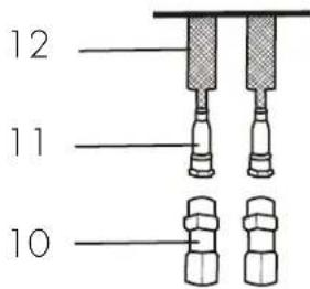
ACCESSIONS
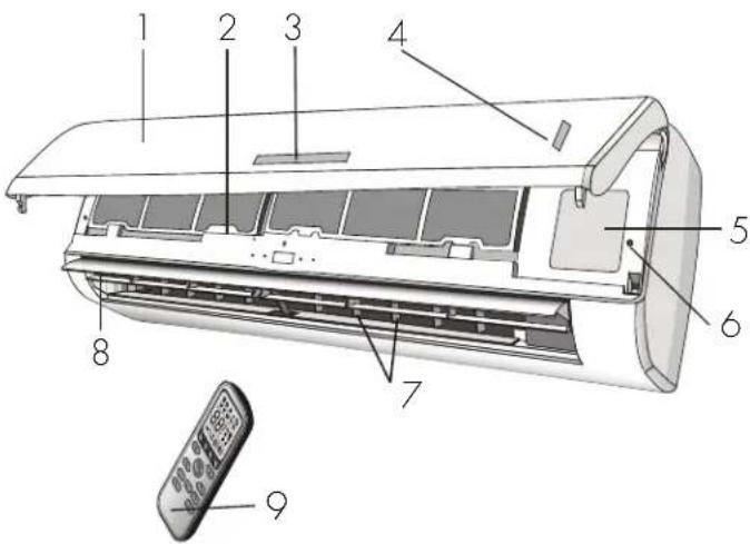
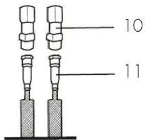
The air conditioning system comes with the following accessories. Use all of the installation parts and accessories to install the air conditioner. Improper installation may result in water leakage, electrical shock, fire or may cause the equipment to fail.
- Front panel
- Air filter
- LED display
- Signal receiver
- Terminal block cover
- Emergency button
7.Deflectors
- Airflow direction flaps
- Remote control
- Male quick connections
- Female quick connections
- Connecting pipes
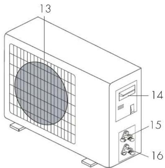
- Air outlet grille
- Big handle cover
15.Gasvalve
16.Liquid valve
Note: The images are for reference purposes only and may not correspond to the actual appearance of the appliance.
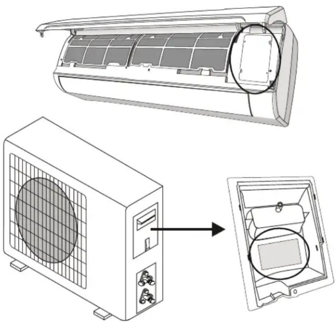
INSTALLATION INSTRUCTIONS
INDOOR APPLIANCE
- Install the indoor appliance on a strong wall that is not subject to vibrations.
- The inlet and outlet ports must not be obstructed.
- Do not install the appliance near a source of heat, steam or flammable gas.
- Install the appliance near an electric socket or a private circuit.
- Do not install the appliance where it will be exposed to direct sunlight.
- Install the appliance where the connection between the indoor and outdoor appliance will be as easy as possible.
- Install the appliance where it will be easy to drain the condensed water.
Install the appliance where the fi iter can be easily accessed.
- Check the operation regularly and leave the necessary space as shown.
- The indoor appliance should be installed at least 8 feet from the ground.
- The indoor appliance requires a minimum of 6'' (15 cm) of space on both sides and the top for proper air flow.
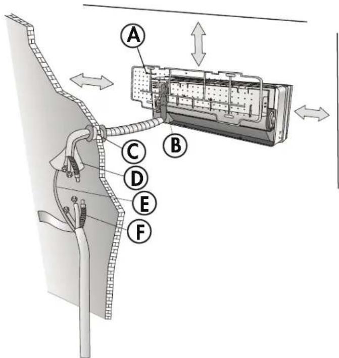
A. Mounting plate
B. Condensed water drain pipe
C. Sleeve
D. Insulating covering
E. Electrical cable
F. Water drain pipe
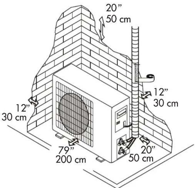
OUTDOOR APPLIANCE
- Do not install the outdoor appliance near sources of heat, steam or flammable gas.
- Do not install the appliance in windy or dusty places.
- Do not install the appliance near a busy walkway or where people usually pass. Select a space where the air discharge and operating sound will not disturb neighbors.
- Avoid installing the appliance where it will be exposed to direct sunlight. A shade or awning should be installed if the appliance will be in direct sun.
- If the outdoor appliance is subject to vibrations, place ribbed gaskets onto the feet.
- Check the operation regularly and leave the necessary space as shown.
INSTALLATION INSTRUCTIONS
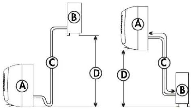
INSTALLATION BREAKDOWN
A. Indoor appliance
B. Outdoor appliance
C. Pipe length is 50 feet (15 meters) maximum.
D. Height is 16 feet (5 meters) maximum.
INSTALL THE MOUNTING PLATE
- Hold the mounting plate on the wall and mark the location of the screw holes. Use a level to ensure the mounting plate is perfectly square.
- Drill 3.2cm deep holes in the wall in the marked locations.
- Insert the plastic anchors into the holes.
- Attach the mounting plate to the wall using the self tapping screws.
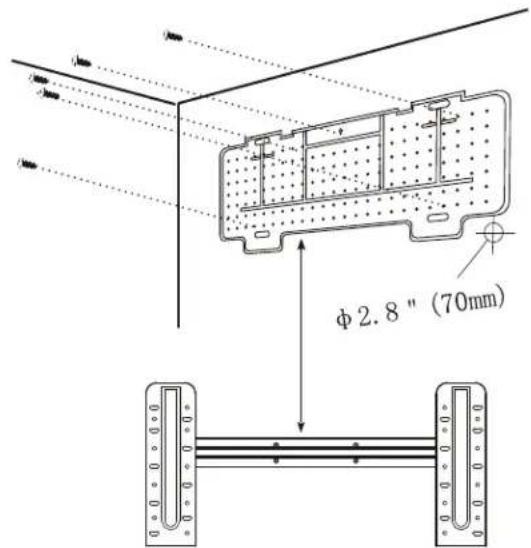
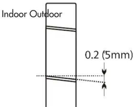
DRILL A HOLE FOR PIPING
- Drill a 2.8'' (7 cm) diameter hole through the wall to accommodate the piping.
- The hole must angle downwards toward the exterior by 0.2^ (5 mm).
- Install a fl exible fl ange into the hole to keep the edges clean and to protect the piping.
INSTALLATION INSTRUCTIONS
ELECTRICAL CONNECTION -INDOOR
- Lift the front panel and remove the cover.
- Follow the circuit diagram to make the connections.
- Connect the cables to the terminals by following the numbering. Use a cable size that is suitable for the electrical power input and according to all current national safety requirements.
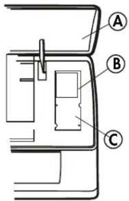
A. Front panel
B. Wiring diagram
C. Terminal block cover
REFRIGERANT PILING SETTING POSITION
Before passing the piping through the wall, bind the copper pipes, the drain pipe and the power cables together with tape. Ensure that the water drain pipe is at the bottom of the group.
WATER DRAINAGE
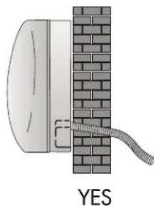
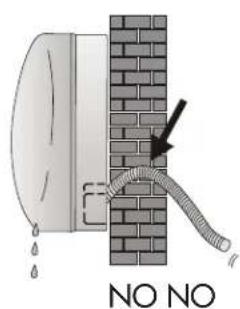
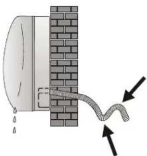
Draining water from the indoor appliance is crucial for correct operation.
- Ensure the drain hose is at the bottom of the pipe, taking care not to create siphons.
- The drain hose must slant downwards.
- Do not bend or twist the drain hose or leave it protruding and do not put the end of it in water. If an extension is connected to the drain hose, ensure that it is lagged when it passes into the indoor unit.
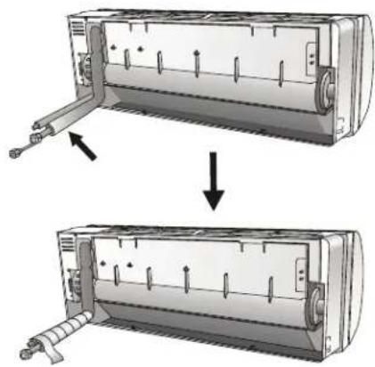
- If the piping is installed to the right, the pipes, power cable and drain hose must be lagged and secured onto the rear of the appliance with a pipe connection.
INSTALLATION INSTRUCTIONS
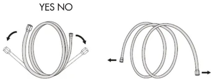
EXTENDING THE PIPES
When extending the rolled pipes, straighten them by unwinding gently as shown. Do not pull from either end as this can cause the pipe to bend or twist.
If the pipes are bent or pulled two often, they will become weak and can leak. Do not bend the pipes any more than three times in any one spot.
Do not remove the cap from the pipes until making the connections to avoid dirt or debris entering the pipes.
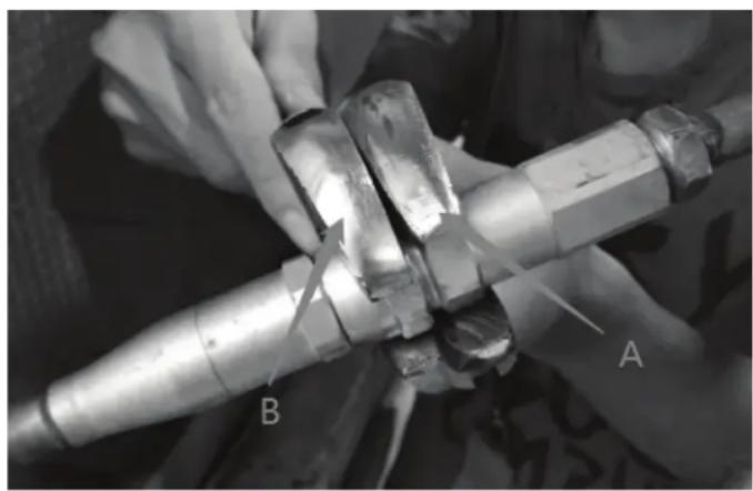
CONNECTING THE INDOOR UNIT
- Remove the cap from the pipe attached to the indoor unit.
- Align the female quick connector to the male end and attach.
- Hold the short position (A) of the male quick connector by open-end spanner and do not turn. Use a torque wrench to hold the short position (B) of the female quick connector which is attached with a long copper pipe and quickly turn to tighten them. Follow the proper torque chart.
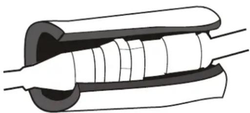
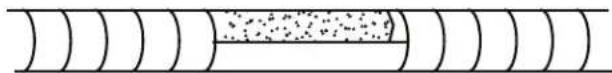
- To protect the quick connector and ensure effcient performance, cover the quick connector with a foam pad.
INSTALLATION INSTRUCTIONS
CONNECTING THE INDOOR UNIT
After connecting the pipe, install the connection cables. Now install the drain pipe. After connection tape the pipe, cables and drain pipe together with the insulating material.
- Arrange the pipes, cables and drain hose well.
- Lag the pipe joints with insulating material, securing it with vinyl tape.
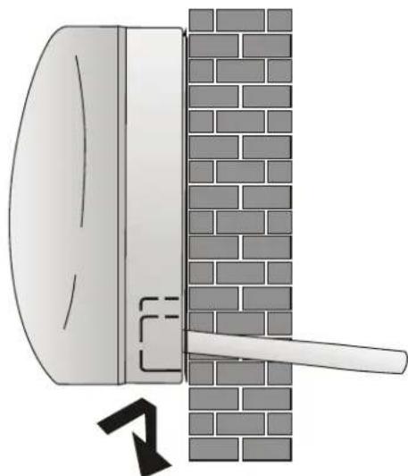
- Run the bound pipe, cables and drain pipe through the wall hole and mount the indoor unit onto the upper part of the mount plate securely.
- Press and push the lower part of the indoor unit tightly against the mounting plate.
A. Connection cable
B. Refrigerant pipe
C. Insulation sleeve
D. Refrigerant pipe
E. Condensed water drain pipe
INSTALLATION INSTRUCTIONS
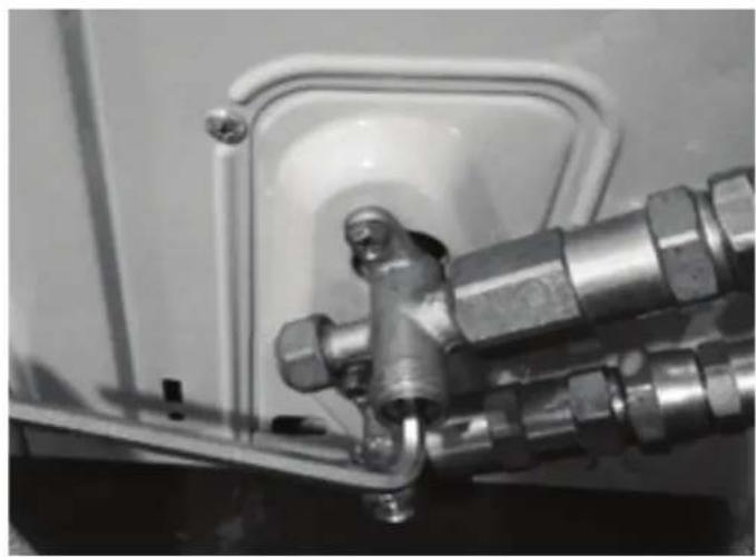
CONNECTING THE OUTDOOR UNIT
Before connecting pipes and cables, ensure the outdoor unit is being installed in an area with enough space for proper air flow and easy maintenance.
Fasten the supports to the wall using screw anchors that are suited to the type of wall. Use a larger quantity of screw anchors than normally required to avoid vibration during operation and to ensure efficienct functioning.
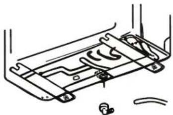
The condensed water and ice formed during operation can be drained through the drain pipe.
Fasten the drain port in the 2.5cm hole placed in the bottom of the unit as shown. Connect the drain port and the drain pipe. Make sure that the water is drained to a suitable place.
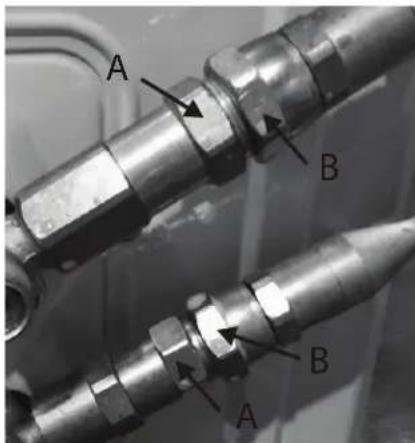
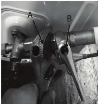
CONNECTING THE PIPES
- Remove the plastic seals from the outdoor unit valve and male quick connectors.
- Align the female quick connector to the male end and attach.
- Hold the short position (A) of the male quick connector by open-end spanner and do not turn. Use a torque wrench to hold the short position (B) of the female quick connector which is attached with a long copper pipe and quickly turn to tighten them. Follow the proper torque chart.
INSTALLATION INSTRUCTIONS
PROPER TORQUE CHART
Note: always perform a leakage check at all connections before operating the appliance.
| Coupling dimensions Pound force | force (1 bf - ft) Newton meter (n - m) Kg force meter (kgf - m) |
| (ø6.35) 9.5 cm dash size 11.8 | 16 1.7 | | |
| (ø9.52) 1.27 cm dash size 11.8 | 8 16 1.7 | | |
| (ø12.7) 1.9 cm dash size 13.3 | 18 1.9 | | |
| (ø16) 2.54 cm dash size 14.8 | 20 2.1 | | |
- Remove the cover of the 2-way and 3-way valves. Use the inner hexagon spanner to open the outdoor valve core by turning it counterclockwise. If the valve core is not opened fully the system may malfunction of suffer damage. Replace the valve cover.
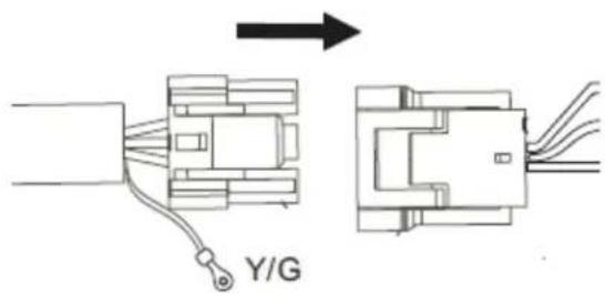
- Connect the wire by plugging the quick connecting cable for both the indoor and outdoor units.
INSTALLATION INSTRUCTIONS
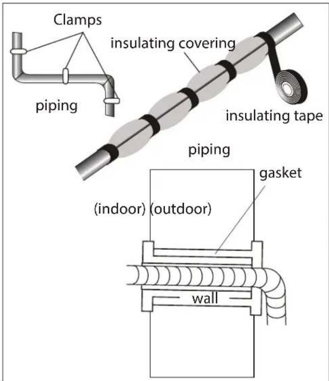
INSTALLATION - FINAL STAGE
- Wind insulation covering around the joints of the indoor unit and secure it with tape.
- Secure the extra length of signal cable to the piping or to the indoor unit.
- Secure the piping to the wall with clamps.
- Seal the hole in the wall through which the piping is passed so that no air or water can pass through.
INDOOR UNIT TEST
- Does the unit turn on and off normally?
- Does the fan operate normally?
- Do the set point and timer operate properly?
- Does each light turn on normally?
- Does the louver operate normally?
Is the condensed water draining?
OUTDOOR UNIT TEST
- Is there any abnormal noise or vibration during operation?
- Could the noise, the air flow or the condensed water drainage disturb the neighbours?
Is there any coolant leaking?
Note: the electronic controller allows the compressor to start only three minutes after voltage has reached the system.
INSTALLATION INSTRUCTIONS
INSTALLATION - INFORMATION FOR THE INSTALLER
| Inverter type model capacity (btu/h) 9K 12K 18K 24K 36K |
| Gas pipe diameter 3/8" | (ø9.52) | 3/8" (ø9.52) | 3/8" (ø9.52) | 1/2" (ø12.7) | 1/2" (ø12.7) |
| Additional refrigerant charge 20g/m 20g/m 20g/m 20g/m 30g/m |
Other notes
Liquid pipe diameter: 1 / 4^ ( 6)
Length of pipe with standard charge: 7.5 meters
Maximum distance allowed between indoor and outdoor units: 15 meters
Maximum difference allowed in level between indoor and outdoor units: 5 meters
Type of refrigerant: R410a
| Tightening torque for protection caps and fl ange connection |
| Pipe Tightening | torque(N x m) | Corresponding stress(using 20 cm wrench) | | Tightening torque (N x m) |
| 1/4" (ø6) 15 - | 20 wrist | strength service | port nut 7 - 9 | |
| 3/8" (ø9.52) | 31 - 35 | arm strength | protection caps | 25 - 30 |
| 1/2" (ø12.7) | 35 - 45 | arm strength | | |
| 5.8" (ø15.88) | 75 - 80 | arm strength | | |
WIRING DIAGRAMS
The wiring diagram may be different for different models. Refer to the wiring diagrams on both the indoor and outdoor units.
On the indoor unit, the wiring diagram is located under the front panel.
On the outdoor unit, the wiring diagram is located on the back of the outdoor handle cover.
Note: Some models will have wires connected to the main PCB of the indoor unit without a terminal block.
INSTALLATION INSTRUCTIONS
CABLE WIRE SPECIFICATION
| Inverter type model capacity (btu/h) 9K | -115V | 12K -115V | 9K -230V | 12K -230V | 24K 36K | |
| sectional area |
| Power supply cable N(L2) 3 mm | | 2AWG12 | 3 mm2AWG12 | 3 mm2AWG12 | 3 mm2AWG12 | 3 mm2AWG12 |
| L(L1) 3mm2AWG12 | 3 mm2AWG12 | 3 mm2AWG12 | 3 mm2AWG12 | 3 mm2AWG12 | 3 mm2AWG12 |
| 3 mm2AWG12 | 3 mm2AWG12 | 3 mm2AWG12 | 3 mm2AWG12 | 3 mm2AWG12 | 3 mm2AWG12 |
| Connection supply cable 3(L) AWG 16 AWG 16 | AWG 16 | AWG 16 | AWG 16 AWG 16 | | | |
| 2(N) |
| 1(S) |
| 3 | |
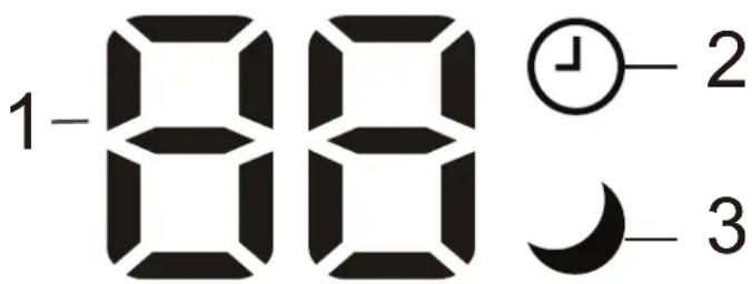
INDOOR UNIT DISPLAY
-
Temperature display:
-
Displays the set temperature
- Displays the error code when a fault occurs
-
Displays time remaining during timer operation
-
Timer: Illuminates during timer operation.
- Sleep: Illuminates when sleep mode is active.
Note: The shape and position of the indicators may be different based on your model but the function is the same.
Note: The display on your indoor unit may only show two numbers for the temperature when three numbers are shown on the remote control. For example, the unit display may show 28^ when the remote control shows 28.5^ .
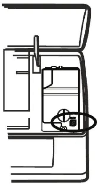
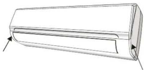
If the remote controller is not working, the indoor appliance can be turned on or off using the manual control button.
Open the front panel, the manual control button will be on the right hand side.
- Press the manual control button once to set the unit to run in cool mode.
- Press the manual control button twice to set the unit to run in heat mode.
- Press the manual control buttons three times to turn the unit off.
AUTO Restart
In the case of sudden power failure, the unit will save the last setting in memory and return to normal operation when power is restored.
OPERATING INSTRUCTIONS
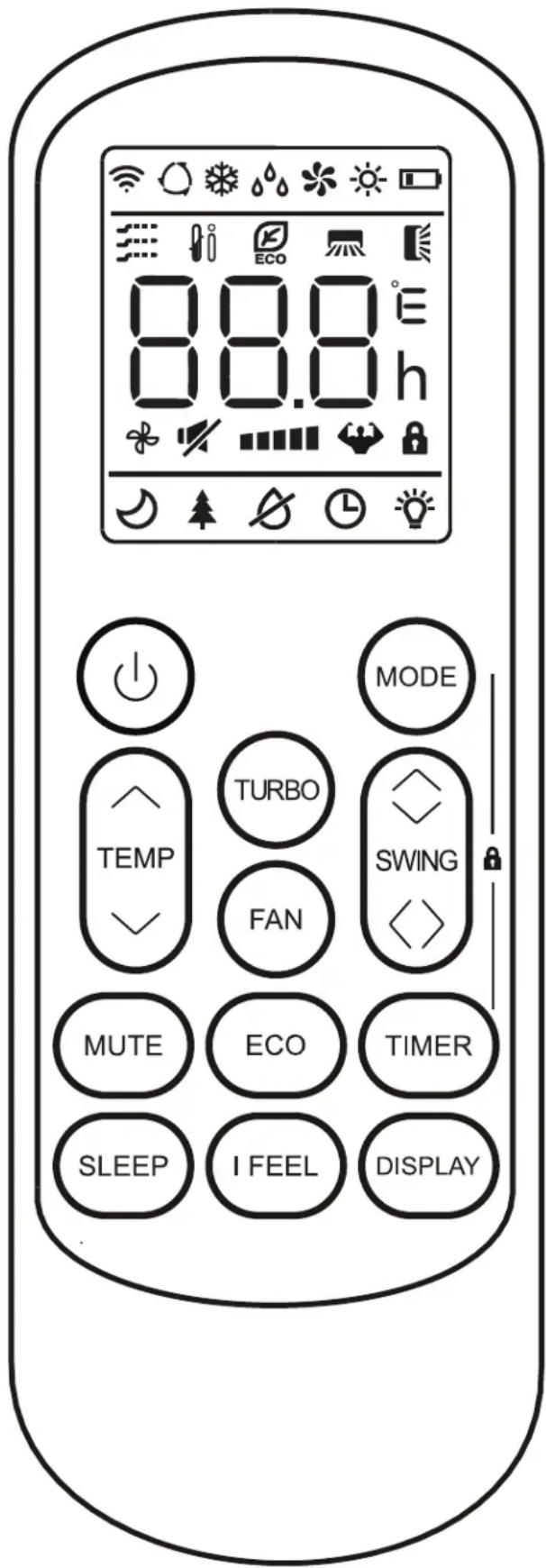
REMOTE CONTROL
- Display: Shows the set temperature, the ambient temperature and the timer settings.
- Power button: Use to turn the appliance on or off.
- Temperature control buttons: Use to adjust the set temperature and to set the timer.
- Mode button: Use to choose the operating mode.
- ECO button: Use to set the energy saver function.
- Turbo button: Use to set the turbo function.
- Fan button: Use to set the desired fan speed.
- Timer button: Use to set the automatic timer.
- Sleep button: Use to set the sleep function.
- Display button: Use to turn the display on or off.
- Swing button: Use to set the desired louver angle.
- Mute button: Use to set the mute function.
- iFeel button: Use to set the iFeel function.
Notes:
- The display and some functions of the remote control may vary based on model.
- The shape and position of buttons and indicators may vary based on model but the function is the same.
- The unit confirms the correct reception of each button press with a beep.
OPERATING INSTRUCTIONS
REMOTE CONTROL DISPLAY
| Symbol Meaning | |
| Battery indicator |
| Auto mode function indicator |
| Cooling mode indicator |
| Dry mode indicator |
| Fan mode indicator |
| Heating mode indicator |
| ECO mode indicator |
| Timer indicator |
| Temperature indicator |
| Fan speed indicator |
| Mute function indicator |
| Turbo function indicator |
| Up and down auto swing indicator |
| Left and right auto swing indicator |
| Sleep function indicator |
| iFeel function indicator |
| Signal indicator |
| Child lock |
| Display ON/OFF |
OPERATING INSTRUCTIONS
REMOTE CONTROL BATTERIES
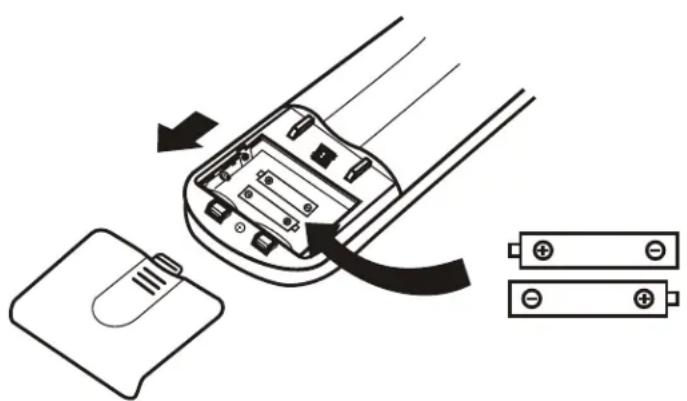
The remote control requires two AAA alkaline batteries (included). Batteries should be replaced when no sound is heard when using the remote control or when the appliance does not respond to a command issued by the remote control.
Battery replacement:
- Slide the rear cover on the remote in the direction of the arrow.
- Insert two AAA batteries following the same orientation depicted inside the battery chamber (+ / - )
- Reinstall the rear cover.
- If the remote control will not be used for extended periods of time, the batteries should be removed.
Notes:
- Protect the remote control from high temperatures, and keep it away from radiation exposure.
- Keep the control panel receiver out of direct sunlight.
- Do not mix old and new batteries.
- Do not mix alkaline, standard (carbon-zinc), or rechargeable (ni-cad, ni-mh,etc) batteries.
- The remote operates within a range of 8 meters (26 ft.) from the receiver located inside the main appliance. Any obstruction between the receiver and remote may cause signal interference, limiting the ability to program the main unit.
REMOTE CONTROL SETTINGS
On some models, when the batteries are replaced, you need to set cooling only or heat pump control type. As soon as you insert new batteries the sun and snowflake symbol will flash on the display.
When the snowflake is displayed, push any button to set the cooling only type remote control.
When the sun is displayed, push any buttons to set the heat pump type remote control.
Note: If the remote is set to cooling only, the heat function will not be available on units that include a heat pump. If you need to reset the unit again, remove and replace the batteries.
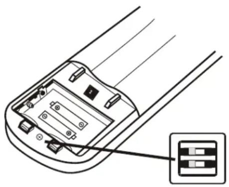
REMOTE CONTROL DIP SWITCH
On some models there is a dip switch inside the battery compartment that can be used to manually set cooling only or heat pump mode.
| DIP switch position | Function |
| °C Display will show | °C |
| °F Display will show | °F |
| Cool Cooling only mode |
| Heat Heat pump mode |
OPERATING INSTRUCTIONS
This Class B digital apparatus complies with the Canadian ICES-003 standard. CAN ICES-3 (B)
This equipment has been tested and found to comply with the limits for a Class B digital device, pursuant to Part 15 of the FCC Rules. These limits are designed to provide reasonable protection against interference in a residential installation.
This equipment generates, uses and can radiate radio frequency energy and, if not installed and used in accordance with the instructions, may cause interference to radio communications. However, there is no guarantee that interference will not occur in a particular installation.
If this equipment does cause interference to radio or television reception, which can be determined by turning the equipment off and on, the user is encouraged to try to correct the interference by one or more of the following measures:
- Reorient or relocate the receiving antenna.
- Increase the separation between the equipment and receiver.
- Connect the equipment into an outlet on a circuit different from that to which the receiver is connected.
- Consult the dealer or an experienced radio/TV technician for help.
Changes or modifi cations not approved by the party responsible for FCC compliance could void the user's authority to operate the equipment. This appliance complies with Part 15 of the FCC Rules.
Operation is subject to the following two conditions:
- This device may not cause interference.
- This device must accept any interference received, including interference that may cause undesired operation.
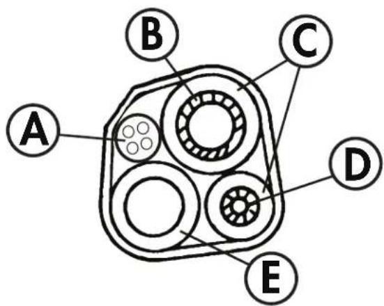
AIR FLOW
Air enters the appliance through the front grill and passes through a fiiter before it is cooled or heated through the heat exchanger.
The direction of the air outlet is motorized up and down by flaps and manually moved left and right by the vertical deflectors. For some models the vertical deflectors are also motorized.
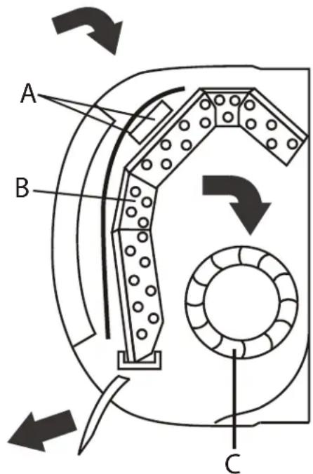
A. Filter
B. Heat
C. Fan
OPERATING INSTRUCTIONS
OPERATING MODES
There are five operating modes to choose from. Press the mode button repeatedly to choose the desired mode. The adjacent indicator light will illuminate to show which mode has been selected.
Cool Mode
Choose cool mode to set the cooling function. Use the temperature control buttons to choose the desired temperature. When cool mode is selected, the fan speed can be adjusted by pressing the fan button.
- Heat Mode
Choose heat mode to set the heating function. Use the temperature control buttons to choose the desired temperature. When heat mode is selected, the fan speed can be adjusted by pressing the fan button.
In heat mode the appliance can automatically enter a defrost cycle to remove frost that has collected on the condenser. This process can last 2 - 10 minutes and the fan will stop operating during this time. After defrosting the appliance will return to regular operation.
- Dry Mode
Choose dry mode to remove excess moisture from the air during periods of high humidity. All water pulled from the air will condense inside the appliance and drain out the back. The fan speed will be automatically set and cannot be modified in dry mode.
- Fan Mode
Choose fan mode to run the internal fan without engaging the cooling function. Press the fan button repeatedly to choose the fan speed: low, med, high or auto.
- Auto Mode
Auto mode is a pre-set factory program that automatically definis the mode and fan speed based on the set temperature, the ambient temperature and the ambient humidity.
OPERATING INSTRUCTIONS
TIMER FUNCTION
To set the Auto-off timer:
- Ensure the appliance is turned on.
- Press the timer button to set the timer to turn the appliance off.
- Press the temperature control buttons to select the desired amount of hours before the appliance turns off.
- Press the timer button to confirm the selection.
To set the Auto-on timer:
- Ensure the appliance is turned off.
- Press the timer button to set the timer to turn the appliance on.
- Press the mode button to set the desired mode.
- Press the fan button to set the desired fan speed.
- Press the temperature control buttons to select the desired amount of hours before the appliance turns off.
- Press the timer button to confirm the selection.
Notes:
- The temperature control buttons will increase the time in 0.5 hour increments up to 10 hours and then in 1 hour increments up to 24 hours
- The display will revert back to showing the previous temperature setting if the appliance does not receive a signal within a 5 second period during programming
- Turning the appliance on or off at any time or adjusting the timer setting to 0.0 hours will cancel the timer settings
SLEEP FUNCTION
The sleep function is used to decrease energy use during sleeping hours. This function can only be activated by pressing the SLEEP button on the remote control.
When in cool mode, the temperature will increase by 1^ (2^) in the first hour and will increase an additional 1^ (2^) in the second hour. The temperature will decrease by 1^ (2^) in 7 hours and another 1^ (2^) in 10 hours.
When in heat mode, the temperature will decrease by 1^ (2^) in the first hour and will decrease an additional 1^ (2^) in the second hour. The temperature will increase by 1^ (2^) in 7 hours and another 1^ (2^) in 10 hours.
At the end of sleep cycle, the appliance will resume normal operation.
Note: The sleep feature is not available in fan and dry mode.
OPERATING INSTRUCTIONS
ECO FUNCTION
The ECO function will automatically cycle the outdoor fan on and off when the compressor is not in use and will minimize compressor running speeds to conserve energy. This function is available in cool and heat modes.
TURBO FUNCTION
Press the turbo button to activate the turbo function, which will run the appliance continuously at high fan speed to reach the preset temperature in the shortest amount of time. The turbo function is available in cool, heat and fan modes.
MUTE FUNCTION
Press the mute button to activate the mute function. Press the mute button again to deactivate the mute function.
When the mute function is active the indoor unit will run the lowest fan speed in order to be as quiet as possible.
The mute function is not available in dry mode. Changing the fan speed or set temperature will cancel the mute function.
IFEEL FUNCTION
This function enables the remote control to measure the temperature at its location and send this signal to the air conditioner to optimize the temperature around you and ensure comfort.
Press the iFEEL button to activate the iFEEL function. It will automatically deactivate after 2 hours. Press the iFEEL button any time to cancel this function.
SWING FUNCTION
Press the swing button to activate the louver swing. Press the swing button again to stop the louver at the desired angle.
There is a button for the horizontal louver and one for the vertical louver.
Never position the louvers manually if that are automatic as the louver motors are delicate and may be damaged.
Do not place fingers, sticks or other items into the air inlet or outlets. Contact with live parts can cause damage or injury.
CARE & MAINTENANCE
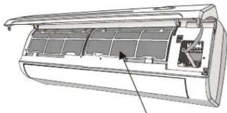
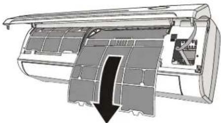
CLEANING THE AIR FILTER
The air fi liter on the indoor unit should be cleaned approximately every 2 weeks. The air fi liter may require more frequent cleaning if there is signifi cant dander or fur in the air.
- Open the front panel.
- Remove the air filter by gently pulling downward.
- Clean the fiiter with warm water. Water should not be hotter than 113^ (45^)
- Ensure the filter is completely dry before replacing in the appliance.
Note: The electrostatic and deodorant fi lter (if installed) cannot be washed and must be replaced with new fi lters every 6 months.
CLEANING THE HEAT EXCHANGER
- Open the front panel of the indoor unit and them remove it by lifting and unhooking it from the hinges to make cleaning easier.
- Clean the heat exchanger using a cloth and water that is not hotter than 113^ (45^) . Never use aggressive solvents or detergents.
- If the battery of the outdoor unit is clogged, remove any leaves or debris by hand and remove any dust with an air jet or with water.
END OF SEASON CARE
- Disconnect the automatic switch or the plug.
- Clean and replace the filters.
- On a sunny day, let the air conditioner run on fan only mode for several hours to ensure that the inside of the unit can dry completely.
ERROR CODES
In the case of an error, the following codes may appear on the display of the indoor unit.
E1 - indoor temperature sensor fault
E2 - indoor pipe temperature sensor fault
E3 - outdoor pipe temperature sensor fault
E4 - refrigerant system leak or fault
E6 - malfunction of indoor fan motor
E7 - outdoor air temperature sensor fault
E8 - outdoor discharge temperature sensor fault
E9 - outdoor IPM module fault
EA - outdoor current detect fault
EE - outdoor PCB EEPROM fault
EF - outdoor fan motor fault
EH - outdoor suction temperature sensor fault
DISPOSAL
Check for local regulatory compliance regarding approved and safe disposal of this appliance.
TROUBLESHOOTING
| PROBLEM POSSIBLE CAUSE |
| The appliance does not start when pressing on/off button | · The appliance has a protection feature that prevents it from being turned back on for 3 minutes after being turned off to avoid overloading
· Room temperature is lower than the set temperature. (Cooling mode)
· Room temperature is higher than the set temperature (Heat mode)
· Power failure
· A fuse is burned out
· Remote control batteries have burned out |
| The appliance changes from cool or heat to fan mode automatically | · The appliance may change mode to prevent frost from forming on the internal coils
· The set temperature has been reached, at which point the compressor is turned off. The appliance will continue operating when the room temperature flUCTuates from the set temperature |
| The indoor or outdoor appliance are emitting white mist | · In humid regions, a large temperature difference between the room temperature and the set temperature can cause white mist
· When the appliance restarts in HEAT mode after defrosting, white mist may be emitted due to moisture generated from the defrosting process |
| The indoor or outdoor appliance are making noise | · A rushing air sound may occur when the louver resets its position
· A squeaking sound may occur after running the appliance in HEAT mode due to the expansion and contraction of internal plastic parts
· A low hissing sound during operation is normal; this is caused by refrigerant gas fl owing through the appliance |
| Dust is emitted from the appliance | · The appliance may accumulate dust on the internal components during long periods of non-use, which will be emitted when the appliance is turned on |
| The appliance emits a bad odor | · The appliance may absorb odors from the surrounding environment, (cooking smells, animal smells, cigarette smells, etc.) which will be emitted during operation
· The fi liter has become clogged and should be cleaned |
| The fan of the outdoor appliance does not operate | · During operation, the fan speed on the outdoor appliance is controlled to optimize product effi ciency |
| Operation is erratic, unpredictable, or appliance is unresponsive | · Interference from cell phone towers and remote boosters may cause the appliance to malfunction. To reset the appliance: disconnect the power then reconnect and press the power button to restart operation |
| Poor cooling or heating performance | · Temperature setting is higher or lower than the ambient room temperature
· The outdoor temperature is extremely high or low
· The air fi liter is clogged
· The air inlet or outlet is blocked
· Doors and windows are open
· Low refrigerant due to leak or long-term use
· The heat exchanger is dirty |
| The appliance starts and stops frequently | · There is too much or too little refrigerant in the system
· Incompressible gas or moisture has entered the system
· The voltage is too high or too low
· The compressor is malfunctioning |
LIMITED APPLIANCE WARRANTY
This quality product is warranted to be free from manufacturer's defects in material and workmanship, provided that the unit is used under the normal operating conditions intended by the manufacturer.
This warranty is available only to the person to whom the unit was originally sold by Danby Products Limited (Canada) or Danby Products Inc. (U.S.A.) (hereafter "Danby") or by an authorized distributor of Danby, and is non-transferable.
TERMS OF WARRANTY
Plastic parts, are warranted for thirty (30) days only from purchase date, with no extensions provided.
First 24 months During the first twenty-four (24) months, any functional parts of this product found to be defective, will be replaced, at warrantor's option, at no charge to the ORIGINAL purchaser.
Nothing within this warranty shall imply that Danby will be responsible or liable for any spoilage or damage to food or other contents of this appliance, whether due to any defect of the appliance, or its use, whether proper or improper.
EXCLUSIONS
Save as herein provided, by Danby, there are no other warranties, conditions, representations or guarantees, express or implied, made or intended by Danby or its authorized distributors and all other warranties, conditions, representations or guarantees, including any warranties, conditions, representations or guarantees under any Sale of Goods Act or like legislation or statute is hereby expressly excluded. Save as herein provided, Danby shall not be responsible for any damages to persons or property, including the unit itself, howsoever caused or any consequential damages arising from the malfunction of the unit and by the purchase of the unit, the purchaser does hereby agree to indemnify and hold harmless Danby from any claim for damages to persons or property caused by the unit.
GENERAL PROVISIONS
No warranty or insurance herein contained or set out shall apply when damage or repair is caused by any of the following:
1) Power failure.
2) Damage in transit or when moving the appliance.
3) Improper power supply such as low voltage, defective house wiring or inadequate fuses.
4) Accident, alteration, abuse or misuse of the appliance such as inadequate air circulation in the room or abnormal operating conditions (extremely high or low room temperature).
5) Use for commercial or industrial purposes (ie. If the appliance is not installed in a domestic residence).
6) Fire, water damage, theft, war, riot, hostility, acts of God such as hurricanes, floods etc.
7) Service calls resulting in customer education.
8) Improper Installation (ie. Building-in of a free standing appliance or using an appliance outdoors that is not approved for outdoor application).
Proof of purchase date will be required for warranty claims; please retain bills of sale.

CONSERVEZ CES INSTRUCTIONS!

INSTALL THE MOUNTING PLATE
Danby Products Limited
PO Box 1778, Guelph, Ontario, Canada N1H 6Z9
Telephone: (519) 837-0920 FAX: (519) 837-0449
1-800-263-2629
12/19
Danby Products Inc.
PO Box 669, Findlay, Ohio, U.S.A. 45840
Telephone: (419) 425-8627 FAX: (419) 425-8629
NOTES / REMARQUES / NOTAS :
NOTES / REMARQUES / NOTAS :
Danby Products Limited, Guelph, ON, Canada N1H 6Z9 Danby Products Inc., Findlay, Ohio, USA 45840
Trademarks of Danby Products Limited and/or its subsidiaries
Marques de commerce de Danby Products Limited et / ou de ses filiales
* Marcas commerciales de Danby Products Limited y / o sus subsidiaries