
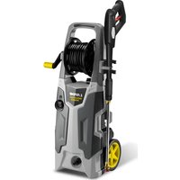
PWR4000 - Pressure washer Lavor - Free user manual and instructions
Find the device manual for free PWR4000 Lavor in PDF.

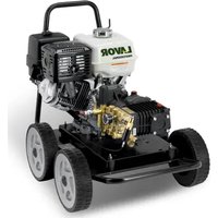
| Product type | High pressure cleaner |
| Brand | Lavor |
| Model | PWR4000 |
| Power source | 4-stroke petrol engine |
| Maximum pressure | 4000 PSI (276 bar) |
| Pump type | Piston pump with oil sump |
| Pressure regulation | Adjustable unloader valve |
| Detergent injection | Injection system with brass soap nozzle and adjustable valve |
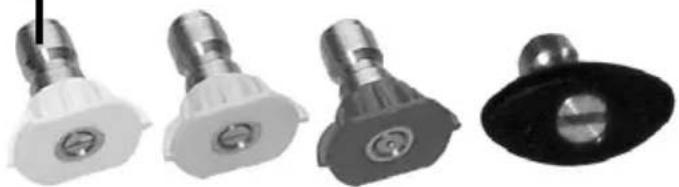
| Included nozzles | High pressure nozzles (0°, 15°, 40°) and low pressure nozzle (soap) |
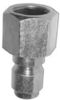
| High pressure hose length | 15.24 m (50 feet) |
| Gun | With trigger and safety lock |
| Safety | Pump thermal protection valve, automatic shutoff due to low oil level |
| Engine maintenance | Oil change SAE 10W-30 every 250 hours |
| Pump maintenance | Oil change 30W non-detergent every 250 hours |
| Water filter | Filter on intake valve, regular cleaning |
| Pump warranty | 12 months against manufacturing defects |
| Other parts warranty | 90 days against manufacturing defects |
| Recommended use | Exterior cleaning, vehicles, patios, facades |
| Precautions | Never direct spray at people or animals, wear protective equipment |
Frequently Asked Questions - PWR4000 Lavor
User questions about PWR4000 Lavor
0 question about this device. Answer the ones you know or ask your own.
Ask a new question about this device
Download the instructions for your Pressure washer in PDF format for free! Find your manual PWR4000 - Lavor and take your electronic device back in hand. On this page are published all the documents necessary for the use of your device. PWR4000 by Lavor.
USER MANUAL PWR4000 Lavor
Component Identification 2
Before You Begin 2
Safety Instructions 2-3
GeneralWarnings&Cautions 3-4
Location,Warnings & Cautions 4
Gas Engine Precautions 5
Electric Motor Precautions 6
Pump Precautions 7
Pre-Operation Checklist 7
Setup & Use 7-8
Operating Instructions 8-9
Shutdown Instructions 10
Winterize the Machine 10
Preventative Maintenance 11
Pressure Washer Troubleshooting 11-14
Gas Engine Troubleshooting 15-16
Electric Motor Troubleshooting 16-17
Pump Troubleshooting 17-19
Pump Pressure Warranty 20
Frame Assembly Instructions 20-21
General EZ Pump Breakdown 22-23
General TP Pump Breakdown 24-25
Comet ZWD Pump Breakdown 26-27
Comet LWD-K Pump Breakdown 28-29
Comet AXD Pump Breakdown 30-31
AR XMV Pump Breakdown 32-33
Cat 5DX Pump Breakdown 34-35
Cat 2DX Pump Breakdown 36-37
Pressure Washer Accessories 62-63
Identification Des Composantes 38
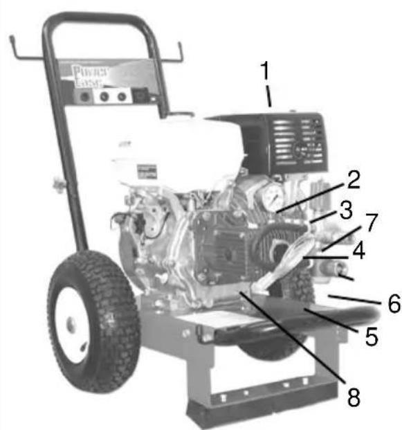
Component Identification
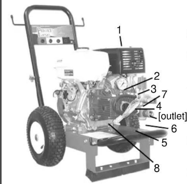
- Engine muffler: Please avoid leaning or placing hand on muffler when turning on or shutting down unit (HOT!!!)
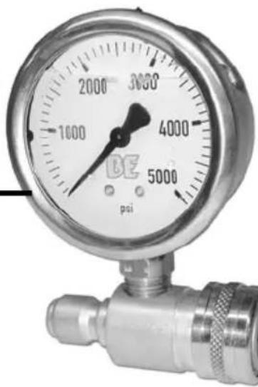
2.Stainless steel gauge: High pressure, glycerin filled
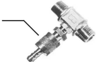
3.Unloader valve: for adjusting the working pressure of the unit - Soap injector Kit: For extra cleaning capabilities.
5.Soap Injector Inlet Hose: For drawing from soap container.
6.Inlet Water Filter: For garden hose. Located near unloader - Thermo Valve: Safeguards pump from overheating
8.Plunger pump: Water cooled
Before You Begin
Read and understand all instructions before operating your pressure washer.
This manual explains how to use your high pressure spray equipment. Be sure everyone who operates, maintains or repairs the pressure washer has read this manual. WARNINGS AND CAUTIONS MUST BE UNDERSTOOD!
Safety Instructions
WARNING
High pressure spray can cause serious injury. This product must be used ONLY by personnel that have been instructed in the safe use of this machine. Observe all warnings when you operate, maintain and repair the pressure washer.
Use this equipment only in well ventilated areas and free of combustible materials, combustible fumes or dust. Failure to follow this warning may cause carbon monoxide build up, fire or explosion, and possible injury or death.
Safety Instructions Continued
To prevent injury wear the following protective clothing:
Gloves Hard Hat Mask
Work Boots Ear Plugs Safety Goggles
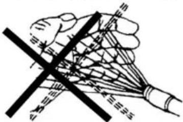

INJECTION HAZARD: Fluids under high pressure from spray or leaks can penetrate the skin and cause extremely serious injury, including death or the need for amputation. You must observe these precautions.
NEVER point the spray gun at people, plants or animals.
NEVER put your hand or fingers over the spray tip.
NEVER try to stop or deflect leaks with your hand or body.
NEVER purchase and use chemicals or detergents that are toxic, flammable, or high in acidic/alkaline base, and always request a material safety data sheet (MSDS) for the product you are purchasing.
NEVER use a powder type detergent or chemical that is not manufactured for pressure washer use; i.e. dish detergent, laundry soap.
General Warnings & Cautions
GET EMERGENCY MEDICAL TREATMENT AT ONCE IF ANY FLUID SEEMS TO PENETRATE YOUR SKIN, EVEN IF THE WOUND DOES NOT APPEAR SERIOUS.
Tell the doctor exactly what fluid was injected and give him the Material Safety Data Sheet for the detergent or chemical product used.
Understand ALL the information this section before you begin to use the pressure washer.
Be sure that all system components and accessory items are original equipment or equivalent.
Be sure the machine is properly located for safe operation.
NEVER alter or modify the pressure washer as personal injury or death could result to humans, plants, or animals, and voids any warranty offered by the manufacturer.
NEVER locate the equipment near combustible materials, combustible fumes, or dust, as personal injury or death could result from fire or explosion.
GeneralWarnings & Cautions Continued
NEVER spray flammable liquids, toxic chemicals (such as incesticide or weed killer) as personal injury or death could result from fire, explosion, or poisoning while damaging the environment.
NEVER allow children or untrained adults to operate the machine.
NEVER wear loose clothing and keep your body and clothing clear of moving parts when the machine is running.
NEVER leave the pressure washer unattended once you have started it. If you must leave, follow complete shut down instructions to prevent unauthorized and untrained personnel from operating the machine.
NEVER move the machine by pulling the hose.
NEVER activate the gun with no nozzle in the wand. This will cause the "O" ring to become dislodged from the coupling and the unit will not function properly.
NEVER put any type of trigger lock onto the gun.
NEVER place hands on motor or pump when unit is running. Keep away from moving parts at all times.
NEVER allow children or animals around your working area.
ALWAYS face nozzle and wand to the ground when testing.
NEVER exceed the pressure rating of the unit's recommended pressure.
NEVER change quick couple nozzles with the nozzle under pressure and without the gun safety in the "on" or "lock" position.
NEVER clean the machine by using its own spray wand.
NEVER run the machine without water.
Location,Warnings & Cautions
The machine must be used at or near the working area and always under trained operator supervision.
The machine should be located as close as possible to the water supply.
Locate the machine on a solid and level surface so that engine and pump crankcase oil lubricates components properly. Avoid areas where water can build up in the working area. Possible injury can occur caused by the surface becoming slippery from water build up.
Locate the machine in a well ventilated area and away from flammable materials or fumes. Be sure ventilation WARNINGS are observed. Keep pressure washer at least 18" away from flammable materials.
Locate the machine so the operator has easy access to the pressure washer and its controls.
Locate the machine so that it is protected from external damage.
To prevent damage and excessive hose wear, locate the pressure washer so that the hose does not cross traffic areas.
Gas Engine Precautions
A FIRE OR EXPLOSION CAN OCCUR RESULTING IN PERSONAL INJURY IF THE FOLLOWING INSTRUCTIONS ARE NOT FOLLOWED:
1 DO NOT fill gasoline tank while engine is running. Allow engine to cool for two minutes before refueling.
2 DO NOT operate the engine when an odor of gasoline is present, or other explosive conditions exist.
3 IF GASOLINE IS SPILLED, move the machine away from the area of the spill and avoid creating any source of ignition until the gasoline has evaporated.
4 DO NOT store, spill, or use gasoline near an open flame, or devices such as a stove, furnace, water heater which utilize a pilot light, or devices which can create a spark.
5 REFUEL OUTDOORS preferably, or in well ventilated areas with UNLEADED GAS ONLY.
6 DO NOT operate engine without muffler. Operating without a muffler, or with a muffler that leaks because of rust or damage, can permit an increased exhaust noise level. Inspect muffler periodically and replace if necessary.
7 DO NOT use this engine on any forest covered, brush covered or grass covered unimproved land unless a spark arrestor is attached to the muffler.
8 DO NOT operate engine if air cleaner or cover directly over the carburetor air intake is removed.
9 DO NOT choke the carburetor to stop the engine.
10 DO NOT TAMPER WITH THE GOVERNOR SPRINGS, GOVERNOR LINKS OR OTHER PARTS WHICH MAY INCREASE THE GOVERNED ENGINE SPEED.
11 DO NOT tamper with the engine speed selected by the original equipment manufacturer.
12 CAUTION - DO NOT RUN AT EXCESSIVE SPEEDS. Operating and engine at excessive speeds increases the danger of personal injury.
13 DO NOT TOUCH hot mufflers, cylinders or fins, as contact may cause burns.
14 TO PREVENT HAND OR ARM INJURY, always pull starter chord rapidly to avoid kickback.
15 READ ENGINE OWNERS/OPERATORS MANUAL BEFORE USING OR ATTEMPTING TO SERVICETHIS MACHINE.
Electric Motor Precautions
DO NOT directly spray electric motor, as shock hazard could occur.
DO NOT allow electric plug to get wet during operation. PLEASE USE WITH CAUTION!
Make sure the unit is in the off position before plugging in.
Do not touch plug with wet hands.
Make sure that you are using the correct voltage and phase
Do not modify the plug provided with the product. If it will not fit the outlet, have a proper outlet installed by a qualified electrician.
Do not use any type of adaptor with this product.
It is recommended to connect your electric pressure washer to a ground fault circuit interrupter. This engine must be grounded. If it should malfunction or breakdown, grounding provides a path of least resistance for electric current to reduce the risk of electric shock. This product is equipped with a chord having an equipment grounding conductor and a grounding plug. The plug must be plugged into and appropriate outlet that is properly installed and grounded in accordance with all local codes and ordinances.
DANGER - Improper connection of the equipment grounding conductor can result in a risk of electrocution. Check with a qualified electrician or service personnel if you are in doubt as to whether the outlet is properly grounded.
Extension Chords
Extension chords are NOT recommended to be used with this product. If an extension chord must be used the following requirements should be met:
Use only 3 wire extension chord that has a three prong grounding type plug with the applicable amperage to match the pressure washer being used.
Use only extension chords that are intended for outdoor use. These extension chords are identified by a marking "Acceptable for use with outdoor appliances; store indoors while not in use" Use only extension chords having an electrical rating not less than that of the product. DO NOT use damaged extension chords and DO NOT yank on any chord to disconnect. Keep chord away from heat and sharp edges. ALWAYS disconnect the extension chord from the receptacle before disconnecting the product from the extension chord. Extension chords MUST be connected to a grounded outlet equipped with a GFCI (Ground Fault Circuit Interruptions). There is risk of electrocution if the extension chord is not connected to a grounded outlet equipped with a GFCI.
Pump Precautions
NEVER allow the pump to run for more than a 3 minute period without opening the gun. (This will cause pump damage due to excessive water temperature and void the warranty)
NEVER let the pump run when the machine is not connected to the water supply. (causing cavitation)
NEVER run acids or hard caustics (such as lye) through the pump.
NEVER use chemicals or agents which are not compatible with the Buna-N and PVC (polyvinyl) or neoprene covering of the hose. (Always use citrus based detergents.)
NEVER use water with a temperature over 140 degrees F.
Check for leaks. Tighten connections if necessary.
Pre-Operation Checklist
□Be sure you understand all the safety precautions and have been instructed in the safe use of the machine.
Wear face and eye protection to prevent injury from spray and flying debris.
Wear protective gloves, rubber boots, and other protective clothing as required.
□Understand all safety precautions and first aid for any detergent or chemical being used.
Check that all lines and hoses are not kinked, twisted or damaged. Replace any damaged hose.
Check that the machine is connected to a water supply and that the water supply is on.
Tighten all fluid connections securely.
Check that oil and fuel levels are at the correct levels before operating. (Pump uses BE-UTFH oil. Engine uses SAE 10-30W. If your pressure washer is equipped with a gear box, use 90W oil for gear box.) (See engine manufacturer's manual for oil change intervals.)
Before starting machine be sure pump is primed and air is purged from the system by allowing water to flow through the pump.
Setup & Use
Follow these instructions for setup and use of your high pressure washer.
- Position the machine on a solid level surface with slopes for drainage to prevent liquid build up on the floor or surface. Position the machine so that the operator has easy access to the pressure washer and its controls. Be sure ventilation WARNINGS are observed.
Setup & Use Continued
- Check and determine that the water supply source is capable of exceeding the output in gallons per minute of the pump. If you are drawing water from a clean static source, rather than a pressure main, the pressure washer must be primed and placed as close as possible to the water source. Be sure the machine is placed on a solid level surface and can not be pulled or bumped into the static source, and the intake hose used must be as large as possible. When drawing water from a pressure source, you need a hose with a 5/8'' outside diameter for lengths up to 50' , or a 3/4'' diameter for lengths up to 100' .
- Connect the high pressure hose to the pressure washer and tighten securely.
Operating Instructions
WARNING
High pressure spray, improperly used could damage the equipment you wish to clean or the surrounding environment. Practice on scrap materials, gradually increasing pressure applied to the object by adjusting the nozzle or moving the nozzle closer to the object until it is cleaned without being damaged.
The manufacturer does not warranty damage caused by the consumer's failure to adjust or operate the machine in accordance with the instructions provided in the owners manual supplied with the machine.
Follow these instructions to operate the machine:
- Use the pre-operation checklist to help avoid personal injury.
- Prime the pump and purge air from the system by squeezing the gun trigger before starting the machine, with the unit attached to a pressure main. Let the water flow from the wand until air is purged from system.
- If engine is equipped with fuel valve, turn valve to ON.
- Close choke lever located on engine carburetor as per engine manufacturer instructions.
- Turn engine switch to ON.
- If engine is equipped with throttle lever, position lever to HALF THROTTLE.
- For easier starting, squeeze the trigger on the spray gun allowing water to pass through gun and grasp the engine starter grip. Pull lightly on the starter grip until resistance is felt, then pull briskly. Repeat this step as necessary until engine starts.
Operating Instructions Continued
- As engine begins to warm up, gradually move the choke lever to OPEN.
- If engine is equipped with throttle lever, position lever to FULL THROTTLE.
- The manufacturer has adjusted the pump pressure to its maximum operating pressure. Simply adjust the pressure required for cleaning with the nozzle as follows when your wand is equipped with: Quick Couple Nozzles: Change nozzles to desired spray pattern (0^, 15^, 40^) or detergent nozzle (the one with the larger orifice) by quick coupling on and off the nozzle. DO THIS ONLY WHEN THE TRIGGER IS NOT SQUEEZED AND THE GUN SAFETY IS ON. NOTE: 0^ is not included with 2005HWCOMXE, 1704HWCOMX or 1604BWCOMX
- You are now ready to start cleaning with your pressure washer. CAUTION: Always begin high pressure washing with the nozzle at least four feet from the object being cleaned and gradually move nozzle closer to the object until it is cleaned without damage.
- To draw chemical/detergent, be sure the pick up tube is installed into the chemical/detergent container with the tube sub merged in the solution. Change wand nozzle to the brass soaper nozzle and squeeze the gun trigger. Adjust the brass knurled chemical knob counter clockwise until proper chemical application is reached. (Adjustment is not available on some models. If no adjustment, simply attaching soaper nozzle will activate the injector.)
Adjusting
Soap Injector
- NEVER allow the pump to run for more than a 3 minute period without opening the gun. This will cause the pump damage due to excessive water temperature and void the warranty. A thermal relief valve has been added to the pump to reduce the possibility of overheating, however, malfunction of this device does not constitute pump warranty for damage caused by overheating.
- As you operate the machine, be sure the inlet garden hose does not become kinked.
- The maximum engine RPM has been set at the factory. TAMPERING WITH ENGINE GOVERNOR WILL VOID PUMP WARRANTY.
- Do not exceed the manufacturer's maximum pressure by increasing the unloader adjustment. (This will void pump warranty.)
Shutdown Instructions
- Run only clean water through the entire chemical/detergent system, then turn chemical/detergent injection valve to OFF. INJECTION HAZARD: Fluids under high pressure from spray or leaks can penetrate the skin and cause extremely serious injury, including death or the need for amputation.
- If engine is equipped with throttle lever, position lever to IDLE.
- Turn engine switch to OFF.
- If engine is equipped with a fuel valve, turn valve to CLOSED position.
- Turn water supply to OFF.
- Open gun to relieve pressure, and drain as much water as possible.
- Remove inlet garden hose.
- For safety and your liability protection, remove high pressure hose and store gun/wand in a secure place with this owners manual to eliminate the possibility of unauthorized and untrained personnel from operating the machine.
Winterize The Machine
Whenever your machine will be subjected to freezing temperatures, severe damage could occur caused by freezing inside the components. To prevent costly repairs, follow these steps: (Freeze damage is NOT covered by the manufacturers warranty.)
- Be sure the machine is OFF, water supply is disconnected, and pressure has been relieved.
- Obtain a one-gallon container or NONTOXIC (RV) antifreeze.
- Install a suction hose from the pump inlet (garden hose fitting) into the NONTOXIC antifreeze. Following operation instructions, start the engine and squeeze trigger on spray gun allowing the pump to draw anti freeze through the entire system. Once antifreeze appears at the end of the wand, turn the engine off.
- Squeeze gun trigger to relieve pressure, and remove the high pressure hose, gun/wand and store in a secure place with the owners manual to eliminate unauthorized and untrained personnel from operating the machine.
- See engine owner's manual for proper engine storage.
- When preparing to operate the pressure washer again, simply reconnect to pressure system water supply, attach the high pressure hose assembly, turn the water to "ON" and squeeze trigger allowing water to pass through the system. (Do not start engine.) Once the liquid becomes clear water at the end of the wand, you are ready to begin operating your pressure washer as referenced in this manual.
Preventive Maintenance
Daily Checks
Regular inspection of your pressure washer is the key to prolong its life.
Follow these simple daily checks
religiously.
- Check air filter for dirt and clean or replace as required.
- Check engine oil level. (Dipstick is attached to inside of oil cap.)
- Check engine fuel level.
- Check high pressure hose for kinks, twists or damage. Replace any damaged hose.
- Check that the pump oil level is within operation range on the pump dipstick or to the centre of the sight glass.
- On units with a gearbox, check that the gear box oil level is within operation range on the gear box dipstick.
- Check that the water supply is adequate for your machine.
- Check water inlet screen and clean when necessary.
- Check the chemical supply.
Preventive Maintenance
-
Change pump oil and, if so equipped, gearbox oil, after every 250 hours. (Pump uses 30W non-detergent oil. If your pressure washer is equipped with a gear box, use 90W oil for gearbox.)
-
See engine manufacturer's manual for oil change intervals.
(Engine uses SAE 10-30W.)
Pressure Washer Troubleshooting
NOTICE: Most problems with pressure washers are not a malfunction of the pump or motor!! ALWAYS trouble shoot from water source and/or nozzle towards the pump and motor. Example: Check water supply and nozzle if pressure fluctuates, unit is noisy or does not reach full pressure.
Follow these trouble shooting rules closely.
Introduction
With proper care and use of the pressure washer, the unit should remain free of problems. Most problems are caused by careless or improper use of the equipment. Operation of the unit without an inlet water supply will result in damage to the seals and other components. Another common cause of damage is running the unit for long periods with the spray gun trigger in its "Closed" position.
The latter can result in high water temperatures, resulting in damage to seals and other components.
Pressure Washer Troubleshooting Continued
Failure of the pressure washer to operate properly is often blamed on a pump failure. Actually only about 10 percent of pressure washer problems are caused by pump failure.
Cavitation
If the water pressure falls below a certain point (called vapor pressure) the water will begin to boil even though the temperatures are below normal boiling point. Tiny bubbles of vapor will then form in the boiling water. If the vapor bubbles are carried away to a higher pressure area in the system the vapor will condense again and leave a cavity in the midst of the flow. The surrounding water will then rush in to fill these cavities. Extremely high local pressures are then created (up to 100,000 PSI). Such high pressures may result in erosion, turbulence, noise, vibration, and excess wear and tear on the pump.
The pump inlet, where the pistons pull the water in, are very susceptible to cavitation problems. Anything that obstructs the flow of water into the pump can result in cavitation such as:
A clogged water inlet filter
Inlet piping or hoses that are too small
- Excessive numbers of restrictions in the water inlet (such as too many valves, or too many bends).
Excessive turbulence or heat
To prevent cavitation, pump inlets must be carefully maintained to avoid restrictions to flow.
Some Pressure Washer Problems
Some of the problems that might occur in a pressure washer system are as follows:
Failure of the unit to produce pressure
Erratic pressure
Chattering
Reduction in pressure
Low water volume
If a Problem Occurs - Some Preliminary Checks
When a problem arises don't remove the pump immediately and start replacing parts. First check the following possible causes of the problem:
Make sure the water supply is turned on and the water supply is adequate
Pressure Washer Troubleshooting Continued
Make sure the water inlet hose is not kinked or damaged
Check the inlet water filter. Clean or replace if necessary
Make sure the water supply is not too hot. Inlet water temperature should not exceed 140^ F
If a detergent is being used, make sure the detergent hose is submerged and not drawing air into the system. If detergent is not being used, the chemical injector valve should be turned off
Make sure the unloader/regulator valve is properly adjusted
Make sure the pump outlet hose is not leaking and is not blocked
Check the wand and high pressure hose quick couplers for missing O-rings
Check that the nozzle is clear and unobstructed
More Troubleshooting Tips
- If the pump is running but produces no flow, try priming the pump.
a) To prime the pump, keep suction at a minimum and keep the discharge line open
b)Open and close the spray gun trigger repeatedly to aid the priming process - A chattering noise usually indicates a restricted water supply or air leaks.
a)Check for kinks or leaks in the hoses
b)look for a plugged or damaged inlet water filter
c)If the filter has been damaged, sediment may have entered the pump. The sediment will be lodged in the inlet valve(s) and must be removed. - Damage to the pump can result from
a) inadequate water supply,
b)vacuum lift too high, or
c)excessive water temperature. - Check the pump crankcase for correct oil level and for oil contamination. If oil appears milky, water has entered the oil and the piston seals should be replaced.
Problems With Detergent
Problems with the use of detergent are often caused by incorrect procedures on the part of the operator. Problems encountered that involve the use of cleaning agents can often be attributed to one or more of the following:
- Wrong Nozzle: Use the brass soaper nozzle when using detergents.
- Hose is not fully submerged in solution: If the tube is not fully immersed, the unit will be picking up air.
- Injection valve is closed: The detergent valve must be open in order to pick up detergent.
Pressure Washer Troubleshooting Continued
- Wrong type of detergent: Only those soaps designed specifically for pressure washers should be used. Household detergents could damage the pressure washer.
Most Frequently Asked Questions
What kind of oil should I use?
Engine: Check engine manufacturer's manual (SAE 10-30W).
Pump: 30W non-detergent
Gearbox: If your pressure washer is equipped with a gearbox, use 90W oil.
My Pressure Washer won't start...
Are engine controls set properly?
Do you have fuel in your machine?
How do I get the soap suction to work?
Replace the high pressure stainless steel nozzle with the brass soaper nozzle.
How do I adjust the pressure at the Unloader?
Turn the unloader/regulator knob clockwise to increase pressure and counter-clockwise to decrease pressure.
I don't have any water pressure...
Do you have any kinks, leakage, or blockage in hoses, fittings or nozzle?
Is the brass soaper nozzle attached to the end of the lance?
Have you let the unit run in bypass for longer than 3 minutes (pump running, gun trigger not depressed)
Have you checked the nozzle for excessive wear?
Gas Engine Troubleshooting
| Problem Engine will not start | Possible Cause 1. Throttle lever on/off switch in OFF position 2. No fuel in engine 3. Worn fouled or dirty spark plug 4. Pressure build up in pump | Remedy 1. Turn throttle lever to ON position 2. Fill fuel tank or turn on fuel supply 3. Replace with factory recommended spark plug 4. Squeeze trigger on spray wand (refer to operating instructions in owner's manual) |
| Units with Oil Alert or Oil Guard Systems | Engine not level or Engine oil level too low | Place engine on level surface or Fill crankcases with oil (refer to engine manufacturers instruction manual) |
| Engine with low power | 1. Possible internal engine problem 2. Partially clogged gun nozzle | 1. Return it to an authorized engine repair center. If engine is equipped with throttle lever, make sure engine is running at full throttle. 2. Clean nozzle of any blockage |
| Engine runs well at no load but “bogs” down under full load | 1. Engine speed is too slow | 1. Contact your pressure washer dealer |
| Engine will not start; or starts and runs rough | 1. Low oil level 2. Dirty air cleaner 3. Out of gasoline 4. Stale gasoline 5. Sparkplug wire not connected to spark plug | 1. Fill crankcase to proper level 2. Clean or replace air cleaner 3. Fill fuel tank 4. Drain gas tank, fill with fresh fuel 5. Connect wire to spark plug |
Gas Engine Troubleshooting Continued
| 6. Bad spark plug 7. Water in gasoline 8. Overchoking 9. Excessively rich fuel mixture 10. Intake valve stuck open or closed 11. Engine has lost compression | 6. Replace spark plug 7. Drain gas tank, fill with fresh fuel 8. Open choke fully and crank engine 9. Contact authorized engine service outlet 10. Contact authorized engine service outlet 11. Contact authorized engine service outlet | |
| Engine shuts down during operation | 1. Out of gasoline 2. Low oil level | 1. Fill fuel tank 2. Fill crankcase with oil, to proper level |
| Engine lacks power | 1. Dirty air filter | 1. Replace air filter |
| Engine “hunts” or falters | 1. Choke is opened too soon | 1. Move choke to halfway position until engine runs smoothly * All engine servicing to be taken to manufacturer’s authorized service outlet |
Electric Motor Troubleshooting
| Problem Motor will not start and there is no humming sound | Possible Cause 1. Not plugged in 2. “RESET” button on GFCI not pushed 3. Circuit breaker has tripped or fuse is blown | Remedy 1. Plug in 2. Push “RESET” button 3. Reset breaker or replace fuse |
| Power source circuit continues to trip or blow fuses | 1. Too much load already on circuit | 1. Reduce load on circuit and try another compatible amp circuit |
Electric Motor Troubleshooting Continued
| 2. Extension cord is too long or of improper gauge, causing voltage drop 3. Pump is stuck due to dirt, mineral build up, or ice 4. Motor malfunction | 2. See section on extension cords 3. Unplug unit. If temp. is below freezing do not use. Thaw in warm area. 4. Take it to your closest Baldor dealer for servicing * All motor servicing to be taken to manufacturer's authorized service outlets |
Pump Troubleshooting
| Problem No low pressure detergent delivery | Possible Cause 1. Nozzles set on high pressure 2. Siphon hose or filter is plugged 3. Incorrect nozzle size | Remedy 1. Push nozzle forward for variable nozzle units, or replace with brass soaper nozzle 2. Unplug siphon hose 3. Install correct brass soaper nozzle |
| Unit does not reach required pressure | 1. Restricted or insufficient water supply 2. Unsuitable or worn out nozzle 3. Regulator set too low | 1. Check supply hose, faucet and inlet water filter. Must be connected to water source which provides 6GPM 2. Replace nozzle 3. Reset unloader by turning knob (clockwise increases pressure) |
Pump Troubleshooting Continued
| 1. Restricted or insufficient water supply or air in the water line 2. Water temperature is too high 3. Pump has operated more than 3 minutes without pulling trigger 4. Pump sucking air 5. Inadequate water supply 6. Thermal relief valve stuck open | 1. Check supply hose, fauce and inlet water filter 2. Use cool water only, maximum 140° F 3. Pull trigger at least 30 seconds every 3 minutes 4. Check chemical/soap injection system 5. Connect to water supply of at least 6GPM 6. Return unit to your pressure washer dealer for servicing | |
| 1. Water leak in high pressure fittings, hose or gun | 1. Use teflon tape or pipe sealant to tighten hose fitting, replace hose or gun If problem continues, take to your pressure washer dealer | |
| 1. Nozzle in low pressure mode 2. Low unloader/regulator pressure 3. Water inlet filter is blocked 4. Inadequate water supply 5. Inlet garden hose is kinked or leaking 6. Detergent line is not submerged 7. Water supply is over 140° F | 1. Insert stainless steel high pressure nozzles 2. Adjust unloader/regulator to desired setting 3. Clear inlet filter screen 4. Provide adequate water flow (at least 6GPM) 5. Straighten inlet hose or patch leak 6. Submerge detergent line 7. Provide cooler water supply |
Pump Troubleshooting Continued
| 8. High pressure outlet hose is blocked or leaks 9. Spray gun leaks 10. Nozzle is obstructed 11. Pump is faulty | 8. Clear blockage in high pressure outlet hose 9. Replace spray gun 10. Clear nozzle 11. Return unit to your pressure washer dealer | |
| 1. Detergent adjustment closed 2. Inadequate water supply 3. Nozzles in high pressure mode 4. Water restriction | 1. Turn adjustment knob counter clockwise to open 2. Connect to water supply that will sufficiently supply 6GPM to pump 3. Replace high pressure stainless steel nozzle with brass soaper nozzle (black) 4. Remove wand/nozzle and check for detergent delivery - if you have soap, check and clean nozzle and all fittings removing scaling or other restrictions If problem continues, take to your pressure washer dealer |
NOTE: Most detergent delivery problems can be prevented by:
1. Using citrus based detergents
2. Flushing the chemical/detergent system before storing
3. NEVER use powdered detergents that are not manufactured specifically for use in pressure washers (ie dish detergent)
| 1. Water temperature too high 2. Thermal relief valve stuck open | 1. Use cool water only, maximum 140° F 2. Return unit to your pressure washer dealer for servicing |
Pump Pressure Warranty
Pressure washers built by the manufacturer are warranted against any manufacturers defects that may occur to their pumps, or gearboxes, for a period of 12 months from the date of purchase. In the case of a defect, please return the entire pump, with a copy of your bill of purchase, to the dealer from whom you purchased your pressure washer for possible warranty replacement
Engines/Motors are warranted by their manufacturers. Engine/motor warranty repair work must be done by an authorized repair depot.
The manufacturer warrants all other parts and components not listed above, for a period of 90 days from the date of purchase against manufacturer's defects. ALL labor done to the unit must have an authorized manufacturer repair number to qualify for warranty.
Pressure Washer units sold for commercial use will carry a limited warranty on all parts and components, for a 90-day period from the date or purchase against manufacturer's defects.
This warranty does not cover merchandise or components thereof, which, in the opinion of the company, has been subjected to negligent handling, misuse, alterations, an accident, or if repairs have been made with parts other than those obtainable through the manufacturer.
Frame Assembly Instructions
Single-Handle Frame
- Slide top part of handle into lower part.
- Align holes in the handle, and insert bolt through. Secure threads nut securely. (A)
Frame Assembly Instructions Continued
Large Frame
- If applicable, bolt lower handle onto the frame using the four bolt holes labeled with an (A).
- Slide top part of handle into lower part. Align holes in the handle, and insert bolt through. Secure threads nut securely (B).
Stainless Steel Belt Drive Frame
- Bolt the handle and the feet brackets onto the frame through the same holes (labelled A). Place the feet brackets between the handle and the frame.
- If applicable, bolt the feet onto the feet brackets through the holes labelled with a (B).
- Bolt bumper on opposite end (C).
- Slide axle through the axle tube (D).
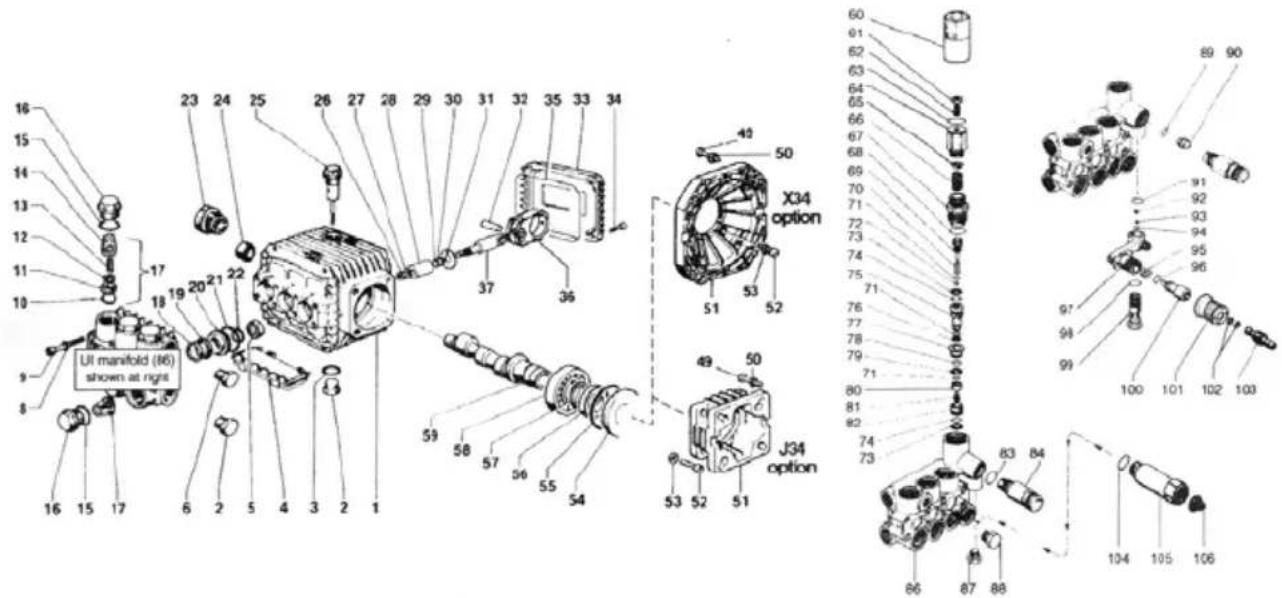
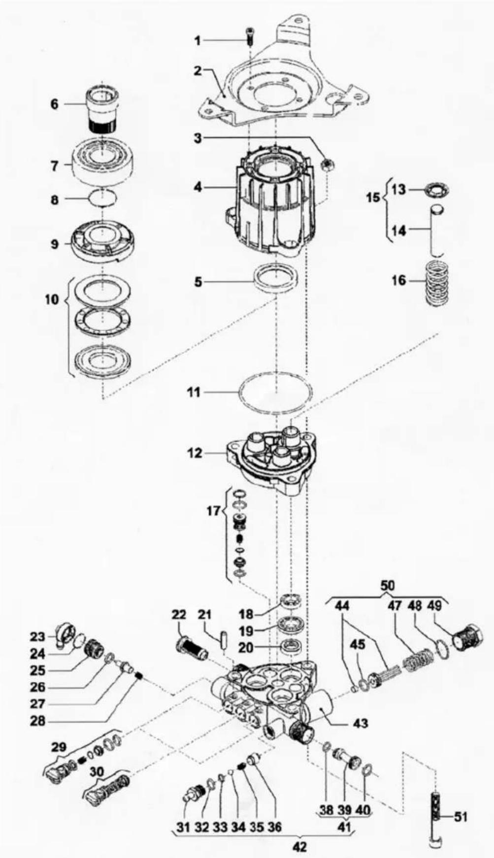
ITEM PART DESCRIPTION QTY.
144120041 PUMP HEAD 1
2 99317500 SCREW 8
3 96701400 WASHER 8
4 90384100 O-RING 6
5 36200366 VALVE SEAL 6
636200176VALVE6
7 94737600 SPRING 6
8 36202551 VALVE CAGE 6
9 90384700 O-RING 6
10 98222600 CAP SCREW 6
11 36711501 VALVE ASSEMBLY 6
12 99180700 SCREW4
13 50150074 BEARING COVER 1
14 44211801 SPACER 1
15 90409700O-RING1
16 91832800BALLBEARING 1
17 90161400 OIL SEAL 3
18 44010022 CRANKCASE 1
19 98210300 OIL DIP STICK 1
22 44050066 PISTON GUIDE 3
23 44030022 CONNECTING ROD 3
24 90392000 O-RING1
25 44160022 REAR COVER 1
26 99183700 SCREW5
27 90358500 O-RING1
28 98204100 CAP SCREW 1
29 97734000 PIN 3
30 96735000 WASHER 3
31 90502200 ANTI-EXT. RING 3
32 90357200 O-RING 3
33 52040009PISTON 3
34 96700800 WASHER 3
35 92221600 NUT 3
40 90361200 O-RING 3
41 44080070 PACKING RETAINER 3
42 52216670 INTERMED. RING 3
43 90262200 PACKING 3
44 90262000 PACKING3
45 51100051 HEAD RING 3
General EZ Pump Breakdown
ITEM PART DESCRIPTION QTY.
46 98210000 CAP SCREW 1
47 98217600 CAP SCREW 1
48 96738000 WASHER 1
49 96751400 WASHER 1
50 98196600 CAP SCREW 1
51 90261700 SEA.; LOW PRESS. 3
75 90063500 RETAINING RING 1
76 44020965 CRANKSHAFT 1
77 91856800 ROLLER BEARING 1
7890409700O-RING1
79 99275500 SCREW, 5/16 X 1 4
99334500 SCREW, 3/8 X 1 4
80 96702000 WASHER 08MM 4
96710400 WASHER 010 MM 4
81 10051822 GAS FLANGE 1
82 90169000 OIL SEAL 1
83 96693800 WASHER 4
84 99191200 SCREW 4
Seal Kit: 3 x RKI130 (3040G)
Seal Kit: 3 x RKI156 (4040G)
Valve Kit: RKI123
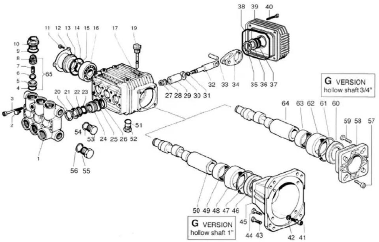
ITEM PART DESCRIPTION QTY.
151010622 CRANKCASE 1
298210000 PLUG,3/81
3 90383300 O-RING 1
4 51209102 PROTECTOR 1
5 90156500 OIL SEAL 3
6 98204100 PLUG, 1/4 1
8 96693800 WASHER 8
9 99194300 SCREW 8
10 90384100 O-RING 6
11 36200366 VALVE SEAT 6
12 36200176 VALVE PLATE 6
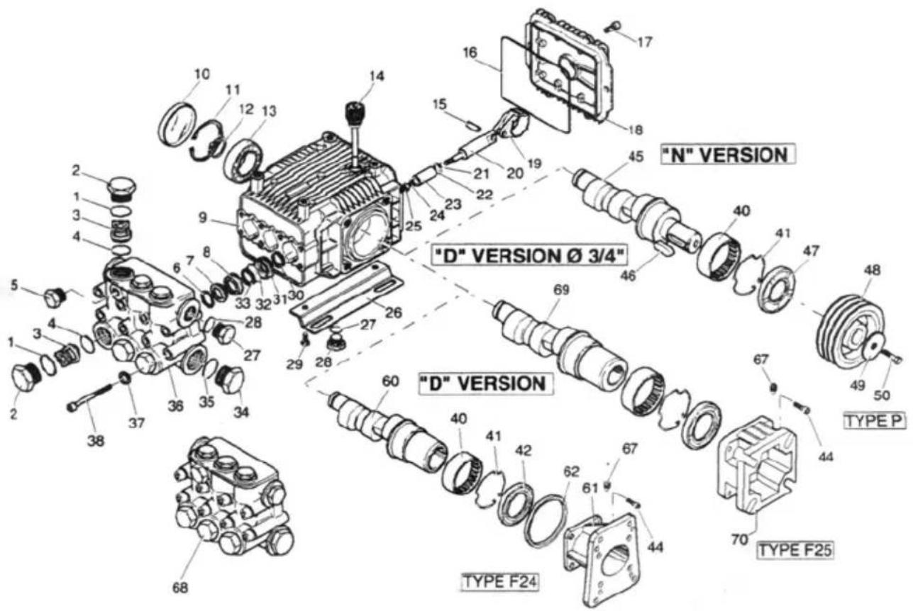
General TP Pump Breakdown
ITEM PART DESCRIPTION QTY.
57 90066700 SNAP RING 1
58 20283521 BEARING 1
59 51022165 CRANKSHAFT 1
60 36318751 KNOB 1
61 99306800 BOLT, M8 X 25 1
62 99222300 NUT, M8
63 90359800 O-RING.20.35 X 1.78
64 36318570 PRESSURE REGULATOR
65 36316970 SEAT
84 10007870 NIPPLE, 3/8 BSPP 1
10014770 NIPPLE, M22 (optional)
10031870 NIPPLE, 3/8 NPT (optional)
8651120141 UI MANIFOLD 1
87 98205700 CAP 1
8898204100CAP 1
89 90382200 O-RING 1
90100151662MMNOZZLE1
91 90358200 O-RING 1
92 94821700 SPRING 1
93 97478200 BALL 1
94 90357200 O-RING 1
Seal Kit: 3 x RKI096
Valve Kit: RKI123
ITEM PART DESCRIPTION QTY.
1 3218012600 MANIFOLD 0 15 BRASS 1
3218012700 MANIFOLD 0 15 BRASS 1
23202001800CAPG1/81
3 3609015200 SCREW M8 X 55 8
3609015600 SCREW M8 X 55 8
4 1210004600 O-RING 2,62 X 17,13 MM 6
5 3009008700 VALVE SEAT 6
6 3604001700 VALVE PLATE 6
71802017700SPRING6
8 1205002500 VALVE GUIDE6
9 1210004800 O-RING 2,62 X 20,24 MM 6
103202023900CAP
11 3609008800 SCREW M5 X 10 3
12 1004001200 CRANKCASE COVER
13 0402017200 SPACER
14 1210038600 O-RING 3,53 X 44,04 MM 1
15 3019001100 SNAP RING
16 0438006900 BALL BEARING 20 X 52 X 15 MM
17 0403012800 CRANKCASE
0403014100 CRANKCASE
19 3200005100 OIL DIPSTICK
20 0009019600 HEAD RING O15 MM
21 1241003400 PACKING O15 MM
22 0009022300 RING O15 MM
23 1241003000 PACKING 15 X 22 X 5,5 MM
24 0009022200 RING O15 MM
25 1210022300 O-RING 1,78 X 26,7 MM
26 0019009500 OIL SEAL 15 X 24 X 5 MM
27 0600004800 NUT
28 2811008000 WASHER 8,2 X 14 X 1,5 MM
29 0202002000 PISTON O15 MM
30 2812003800 WASHER
6
1
1
3
Comet ZWD Pump Breakdown
ITEM PART DESCRIPTION QTY.
31 1210005500 O-RING 1,78 X 6,07 MM 3
32 2409004400 PISTON GUIDES 3
33 3011001400 WRIST, PIN 3
34 0205005000 CON. ROD 3
35 3019003300 SNAP RING O18 MM 1
36 3201001200 OIL INDICATOR 1
37 1210033300 O-RING 1,78 X 23,52 MM 1
38 1210020600 O-RING 2,62 X 101,27 MM
39 0402022000 CRANKCASE COVER
40 3609004100 SCREW M6 X 25
41 3609003200 SCREW M6 X 20
42 2811002300 WASHER 6,6 X 18 X 2 MM
43 3607016800 SCREW 3/8" 16 X 1"
44 3607011900 SCREW 5/16" 24" X 1"
45 3016002300 FLANGE 1"
46 0019010200 OIL SEAL 40 X 62 X 7 MM
47 3020001200 SNAP RING C 72
48 0204003800 BUSHING
49 0437004500 ROLLER 40 X 47 X 16 MM
50 0001038600 CRANKSHAFT 1"
0001038600 CRANKSHAFT 1"
0001039800 CRANKSHAFT 1"
51 1210044100 O-BING 2 X 14 MM
52 3200000700 CAP 3/8 GAS OT 58
53 3200000700 CAP 3/8 GAS OT 58
54 2811008400 WASHER 16,7 X 22 X 1,5 MM
55 3202001500 CAP G 1/2
56 2811008600 WASHER 21,2 X 27 X 1,5 MM
65 1220003000 VALVE ASS. BLY.
1
1
Seal Kit: 5019006400
Valve Kit: KIT001
ITEM PART DESCRIPTION QTY.
1 3218011200 MANIFOLD 15mm 1
23202001800CAPG1/8
3 3609010800 SCREW M6x55 8
3609015200 SCREW M6x55 8
4 1210004600 O-RING 2,62 x 17.13mm 6
5 3009008700 VALVE SEAT 6
63604001700 VALVE PLATE 6
71802017700 SPRING
8 1205002500 VALVE GUIDE6
9 1210004800 O-RING 2.62 x 20.24mm 6
10 3202015500 CAP
11 3609008800 SCREW M5 x 10 3
12 1004001200 CRANKCASE COVER
13 0402017200 SPACER
14 1210038600 O-RING 3,53 x 44.04mm 1
15 3019001100 SNAP RING 1
16 0438006600 BALL BEARING 20x52x15mm
0438006900BALL BEARING20x52x15mm 1
17 0403012800 CRANKCASE 1
19 3200005100 OIL DIPSTICK 1
20 0009019600 HEAD RING 15mm 3
21 1241003400 PACKING 15mm 3
22 1241003000 PACKING 15x22x5.5mm 3
23 0009019800 PACKING RETainer 15mm 3
24 1210022300 O-RING 1,78x 26,7mm 3
25 0019009500 OIL SEAL 15× 24× 5mm 3
26 0600004800 NUT 3
27 2811008000 WASHER 8,2x14x1,5mm 3
28 0202002000 PISTON 15mm 3
29 2812003800 WASHER 3
30 1210005500 O-RING 1,78x 6,07mm 3
31 2409004400 PISTON GUIDES 3
32 3011001400 WRIST, PIN 3
33 0205004800 CON.ROD 3
0205005000 CON.ROD 3
34 3019003300 SNAP RING 18mm
35 3201001000 OIL INDICATOR 1
36 1210033300 O-RING 1,78x 23,52mm
37 1210020600 O-BING 2.62x 101.27mm
38 0402014200 CRANKCASE COVER
39 3609004100 SCREW M6x25 4
46 1210044100 O-RING 2x 14mm
423607019900 CREW 5/16" 24 X 3/4"
430019007500OIL SEAL 35X62X7MM 1
443019000400SNAPRING C72 1
45 3020001200 SNAP RING C72
102 2812006400 WASHER 1
103 0438001500 BALL BEARING 35 X 62 X 14 MM 1
0438007000 BALL BEARING 35 X 62 X 14 MM
104 0001033400 CRANKSHAFT 3/4"
0001033500 CRANKSHAFT 3/4"
0001038300 CRANKSHAFT 3/4"
0001038400 CRANKSHAFT 3/4"
0001040600 CRANKSHAFT 3/4"
Seal Kit: 5019003500
Valve Kit: 5025001100
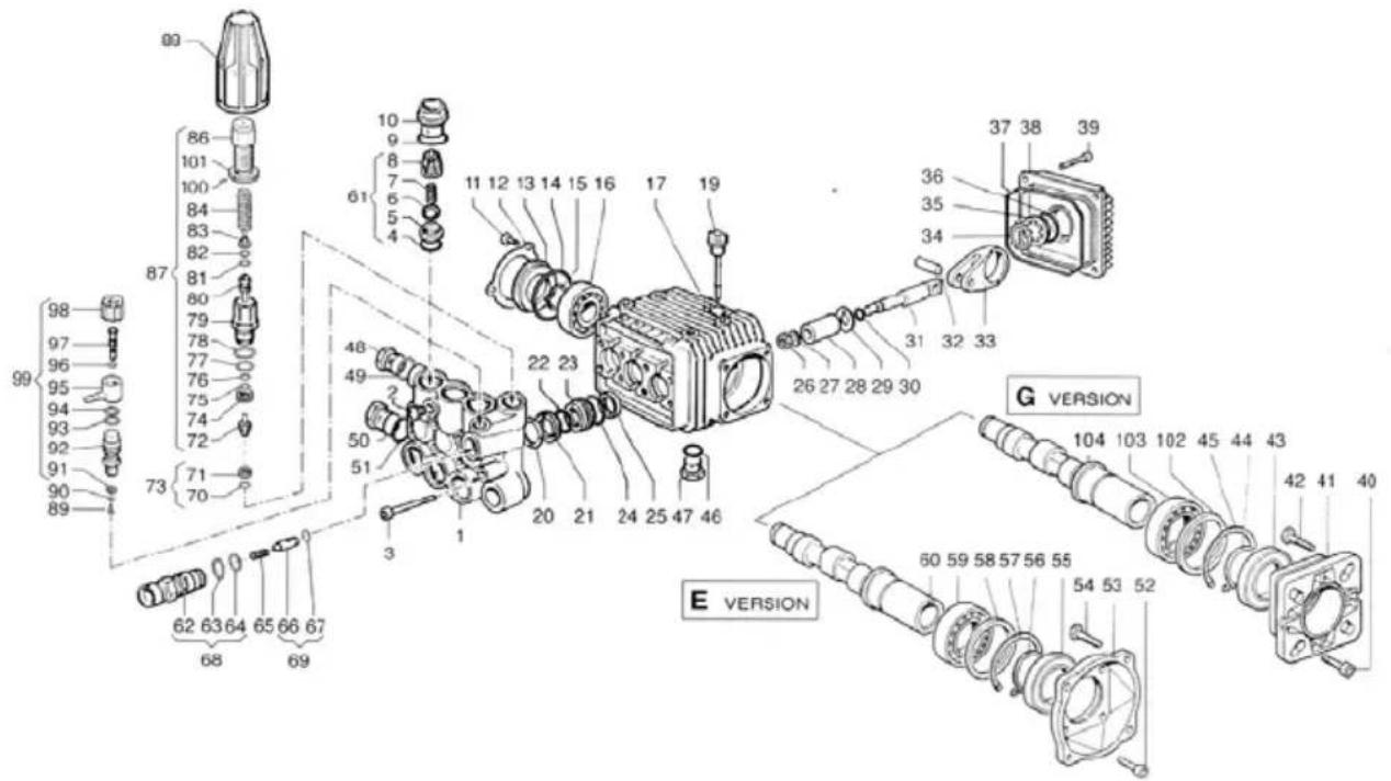
ITEM PART DESCRIPTION QTY.
1 3202001800 CAP 1/8" 1
2 3609015600 SCREW M8x55 4
3 1220004500 VALVE KIT 6
4 1210004900 O-RING 1.78x12.42 6
5 3009012900 VALVE SEAT 6
6 3604002800 SUC./DEL. VALVE 6
7 1802019200 SPRING 6
8 1205003300 VALVE CAGE 6
90601027300SPACER
10 1210015100 O-RING 1,78x17.176
11 3202023600 PLUG 6
12 1215027100 REG.VAL KIT FOR AX 180 BAR
13 1817005300 KNOB 1
14 3622003000 STOP ADJUSTABLE NUT M4x4
15 1227002200 NUT
16 1802018200 SPRING 1
17 0204004600 ADJUSTABLE KNOB 1
18 0009020700 SEAT 1
19 2409007700 PISTON ROD 1
20 1210040600 O-RING 1
21 0009020600 RING 1
22 0204004500 HOUSING 1
23 1210040700 O-RING 1
24 1210040500 O-RING 1
25 0009020500 RING 1
26 1210040400 O-RING 1
27 0009020400 RING 1
28 3002050800 HOUSING WITH BALL 1
29 3009012200 SEAT 1
30 1210040300 O-RING
31 3009001300 VALVE SEAT 1
32 1210035600 O-RING 1,78x25,12 3
33 1241005000 PISTON SEAL 14 3
34 0019010300 SEALING RING 3
35 3201001800 OIL LEVEL PLUG 1
36 1802015300 SPRING 3
37 2409008900 PISTON 3
38 0009022100 RING 3
39 0009022000 RING 14 3
Comet AXD Pump Breakdown
ITEM PART DESCRIPTION QTY.
| 51 04030135.00 PUMP CRANKCASE 1 | |
| 52 36090005.00 SCREW M8x20 4 | |
| 53 34100295.00 INJECTOR BODY M22x1,5 1 | |
| 34100298.00 INJECTOR BODY 3/8" NPT | |
| 54 12100049.00 O-RING 1,78x12,42 | 1 |
| 55 12100040.00 O-RING 1,78x15.6 | 1 |
| 56 34100302.00 INJECTOR BODY KIT M22x1,5 | 1 |
| 34100303.00 INJECTOR BODY KIT 3/8" NPT | |
| 57 18020197.00 SPRING | 1 |
| 58 24090086.00 CHECK VALVE | 1 |
| 59 12100397.00 O-RING | 1 |
| 60 24090091.00 CHECK VALVE KIT | 1 |
| 61 00090219.00 RING | 3 |
| 62 00090230.00 RING | 3 |
| 63 12410055.00 PISTON SEAL 150 BAR | 3 |
| 12410056.00 PISTON SEAL 180 BAR | |
| 64 32000017.00 PLUG 1/8x8 | 1 |
| 65 32000007.00 PLUG 3/8 GAS OT58 | 1 |
| 66 28030435.00 INJECTOR KIT | 1 |
| 67 28030425.00 HOSE BARB FITTING | 1 |
| 68 28120067.00 O-RING | 1 |
| 69 30030026.00 BALL | 1 |
| 70 18020180.00 SPRING | 1 |
| 71 32180299.00 PUMP VALVE CHAMBER | 1 |
| 72 32000017.00 PLUG 1/8x8 | 1 |
| 77 28000081.00 GARDEN HOSE TAIL | 1 |
| E VERSION | |
| 78 36090005.00 SCREW M8x20 1 | |
| 79 28160025.00 THRUST BEARING | 1 |
| 80 04360016.00 AXIAL BEARING | 1 |
| 81 00010431.00 ECCENTRIC SHAFT 6 DEG. | 1 |
| 00010417.00 ECCENTRIC SHAFT 8 DEG. | |
| 00010419.00 ECCENTRIC SHAFT 9 DEG. | |
| 82 04380076.00 BALL BEARING 40x80x18mm | 1 |
| 83 00010422.00 ECCENTRIC SHAFT 5/8" | 1 |
| 84 12100429.00 O-RING | 1 |
| 85 00190034.00 SEALING RING 40x55x7 | 1 |
| 86 30020538.00 SUPPORT | 1 |
| 87 32000071.00 PLUG G3/8 | 1 |
Seal Kit: 5019007700 (2520G, 3020G)
Seal Kit: 5019007800 (3025G, 2020E, 3020E)
Valve Kit: 5025001400
Comet VRX 2017V Pump Breakdown
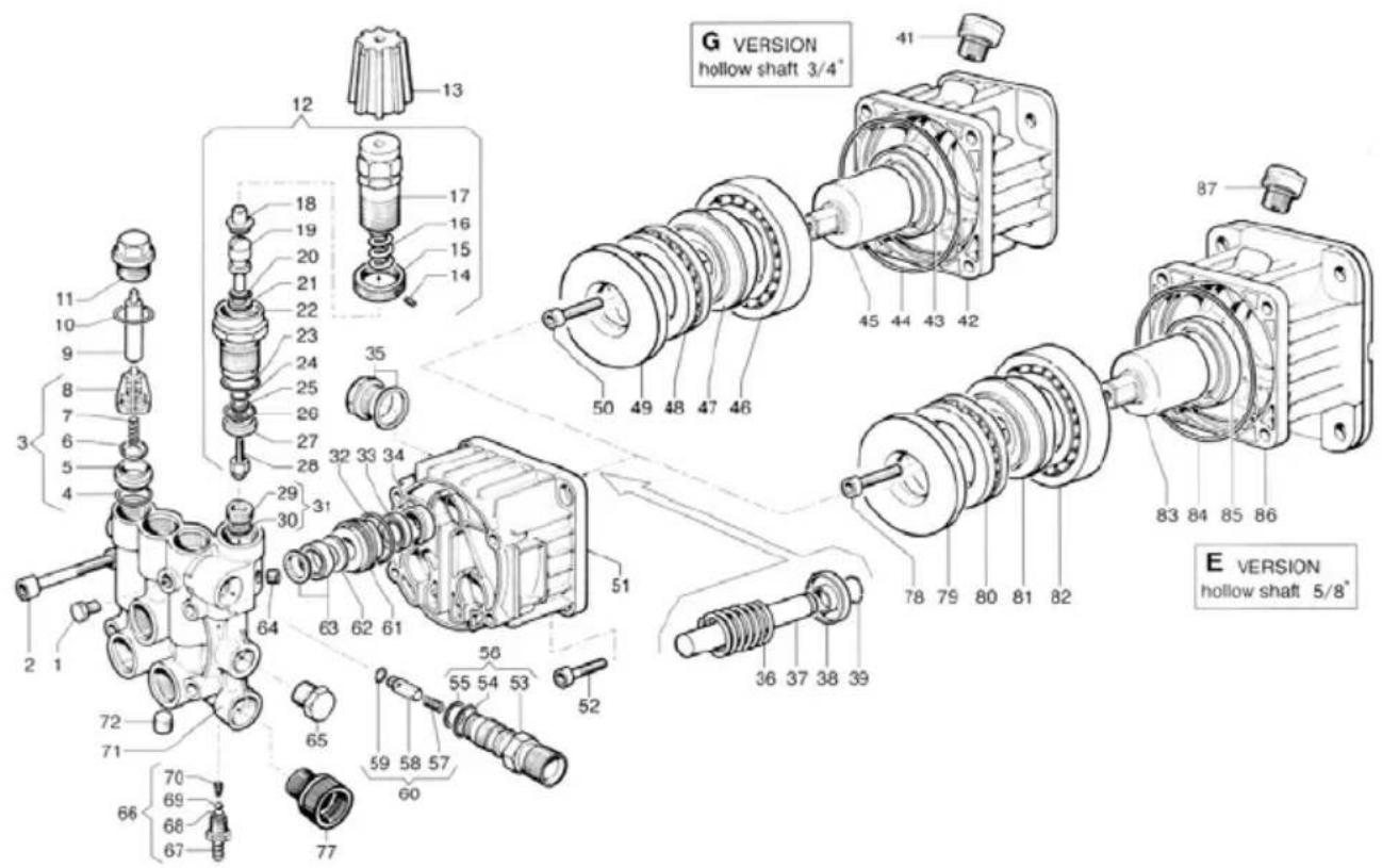
ITEM PART DESCRIPTION QTY.
1 3625005100 SCREW M6x16 4
2 3002055300 SUPPORT 1
3 0604001500 NUT M8 3
4 0403015000 PUMP CRANKCASE 1
50019011200OIL SEAL 35x47x7
60031001300PUMPCRANKSHAFT7/8" L = 46 1 0031001100PUMP CRANKSHAFT7/8" L = 80
70438008400BALL BEARING 30x62x16
8 1210039400 O-RING 2x25
9 0001045900 ECCENTRIC SHAFT
10 0436002000 AXIAL BALL BEARING 1
11 1210039100 O-RING 2.62x75.87
12 2432001800 PUMP CRANKCASE 1
13 0009026700 RING 3
14 2409009900 PISTON 14 3
15 5026026000 PISTON KIT 3
16 1802021300 PISTON SPRING 3
17 1220005400 SUCTION VALVE 3
18 0019011100 OIL SEAL 14x22x5/7 3
19 0009026800 PACKING RETAINER 3
20 1241003300 PACKING 14x22x6 3
21 3021003200 ELASTIC PIN 6x22 3
22 1002013200 SUCTION FILTER
29 1220005700 DELIVERY VALVE 2
30 1220005600 DELIVERY VALVE 1
31 2800010400 DETERGENT STRAIGHT HOSE TAIL
32 1210046500 O-RING 1.78x8.73
33 1210046600 O-RING 1.5x6
34 3003003300 BALL 9/32" 1
35 1802021600 SPRING
36 0204005100 BUSHING 1
38 1210046500 O-RING1.78x8.73 1
39 0801006600 DETERGENT INJECTOR
40 1210017000 O-BING1.78x10.82
41 3410032200 DETERGENT INJECTOR KIT
42 5026026100 DETERGENT KIT 1
43 3218033300 MANIFOLD STD. VERSION
44 0110000300 REGULATION VALVE KIT
45 1210039300 O-RING 2x12
47 1802021500 VALVE SPRING 1
48 1210039200 O-RING 2x16
49 3202027400 PLUG 1
50 5026026400 VALVE KIT 1
51 3609001400 SCREW M8x55 3
THE FOLLOWING ARE FOR THE THERMO VALVE VERSION ONLY
23 2801007900 THERMO VALVE COVER
24 1210004300 O-BING 1.78x11.11
25 0424038100 THERMO VALVE BODY
26 1210047500 O-RING 2.62x9.19
27 3230003100 THERMO VALVE ROD
28 1802021700 SPRING 1
43 3218031100 MANIFOLD 1
Seal Kit: 5026026500
Valve Kit: 5026026300
ITEM PART DESCRIPTION QTY.
1960160O-RING6
2 1260162 PLUG (442 IN lbs) 6
3 1269050 COMPLETE VALVE 6
4880830O-RING6
5620301 PLUG 1
6 1780130 SUPPORT RING 3
7 1260130 GASKET 3
81780090 PISTON GUIDE 3
9 1780010 PUMP BODY
10 1266740 CAP CIRCLIP SNAP RING
11 1260790 BEARING
12 1780550 OIL CAP
13 1780490 BEARING 1
14 880130 OIL CAP
15 1780050 PISTON PIN 3
16 1780510 O-RING 1
17 1200430 SCREW (106 IN lbs) 6
18 1789010 COMPLETE COVER
19 1780040 CON ROD 3
20 1780060 GUIDING PISTON 3
480480 O-RING 3
22 1260091 SPACER DISC 3
23 1780070 PISTON 3
24 1260100PISTONWASHER 3
25 1260110 NUT (106 IN lbs)
26 1380141 BASE 2
27 740290 O-RING 2
28 880530 PLUG 2
29 1260470 SCREW 4
30 1260460 SEAL 3
31 1780100 REAR PISTON GUIDE 3
32 770260 O-RING 2
33 1260440 GASKET 3
34 820360 PLUG1
35 180101 O-RING 1
36 1780380 HEAD (133 IN lbs) 1
37 1381550 WASHER 8
AR XMV Pump Breakdown
ITEM PART DESCRIPTION QTY.
38 1322730 SCREW (133 IN lbs) 8
40 1321190 BEARING 1
41 1321080 SNAP RING 1
42 480671 SEAL 1
44180030 SCREW 4 1780231 CRANK SHAFT
45 1780191 CRANK SHAFT
46 1380520 KEY
47 1260750 SEAL 1
1780590 HOLLOW SHAFT 3/4"
48 1780340 HOLLOW SHAFT 1" 1
60 1780320 HOLLOW SHAFT 1" 1
61 1597 GAS ENGINE FLANGE FOR 1" SHAFT
61 1780580 GAS ENGINE FLANGE FOR 3 / 4^ SHAFT
62 1780430 BUSHING 1
67 820440 GRUB SCREW 1
68 1789200 PUMP HEAD PRE-ASSSEMBLY 1
Seal Kit: AR2741
Valve Kit: AR1864
ITEM PART DESCRIPTION QTY
5 92521 SCREW HHC (M8x20 4
8 46461 COVER, BEARING 1
10 14037 O-RING, BEARING COVER 1
11 46419 SEAL, OIL, CRANKSHAFT 1
13 14037 O-RING, BEARING COVER 1
15 146421 BEARING, BALL-INNER 1
2046677 CONNECTING ROD 3
25 46985 CRANKSHAFT (6.4mm) 30G1 1
46551 CRANKSHAFT (7.9mm) 35G1 1
46460 CRANKSHAFT (9.0mm) 40G1 1
48468 CRANKSHAFT (11.2mm) 50G1 1
27 14480 BEARING, BALL-OUTER 1
32 46798 CAP,DOMED OIL FILLER
33 14179 O-RING, OIL FILLER
37 43987 GAUGE, OIL BUBBLE 1
38 44428 GASKET, FLAT FLEX 1
40 92519 SCREW, HHC (M6x16) 4
48 25625 PLUG, DRAIN (1/4"x11) 1
49 23170 O-RING, DRAIN PLUG 1
50 46379 COVER. CRANKCASE 1
51 14048 O-RING. CRANKCASE COVER 1
5346454 CRANKCASE 1
64 46404 PIN, RIST 3
65 46728 ROD, PLINGER 3
70 29257 SEAL, OIL, CRANKCASE 3
75 46732 SLINGER. BARRIER 3
9046727PLUNGER 3
98 46730 WASHER SEAL, PLUNGER RETAINER 3
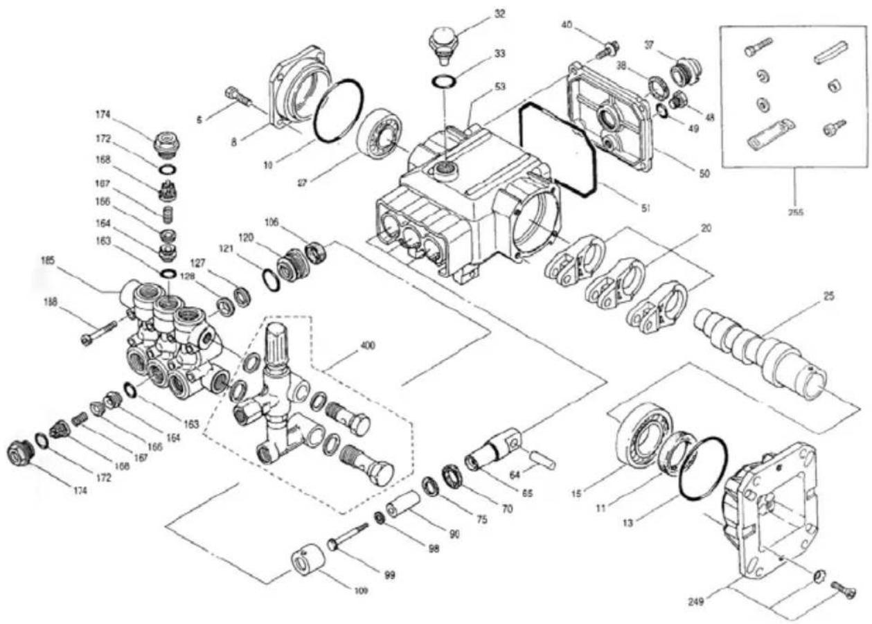
Cat 5DX Pump Breakdown
ITEM PART DESCRIPTION QTY
128 46618 ADAPTOR, MALE 3
163 47547 O-RING, SEAT 85 6
164 46658 SEAT 6
166 46429 VALVE 6
167 43750 SPRING 6
168 46583 RETAINER 6
172 17615 O-RING, VALVE PLUG 75 6
174 46388 PLUG, VALVE 6
185 46526 HEAD, MANIFOLD
188 87868 SCREW, HSH (M8x107)
249 46679 FLANGE, MOUNT
46123 LOCKWASHER, TOOTHED (M8) 4
46403 SCREW, FH (M8x25) 4
255 30519 KIT, BOLT MOUNT 1
34100 SCREW (3/8-16x1-3/8") 4
30921 LOCKWASHER, SPLIT (3/8") 4
30980 WASHER, FLAT (3/8") 4
6106 ANTISEIZE LUBRICANT 1
45217 KEY (1/4"x1/4"x2-1/2") HD 1
34042 SPACER 4
87788 SCREW, SET (M5x^*) 1
300 34062 KIT, SEAL (INCLDS:98,106,121,127,128)
310 34060 KIT, VALVE (INCLDS:163,164,166,167,168,172) 2
4007655 MODULAR UNloader ASSEMBLY 1
7659 MODULAR UNloader ASSEMBLY 1
Seal Kit: 34062
Valve Kit: 34060 x 2
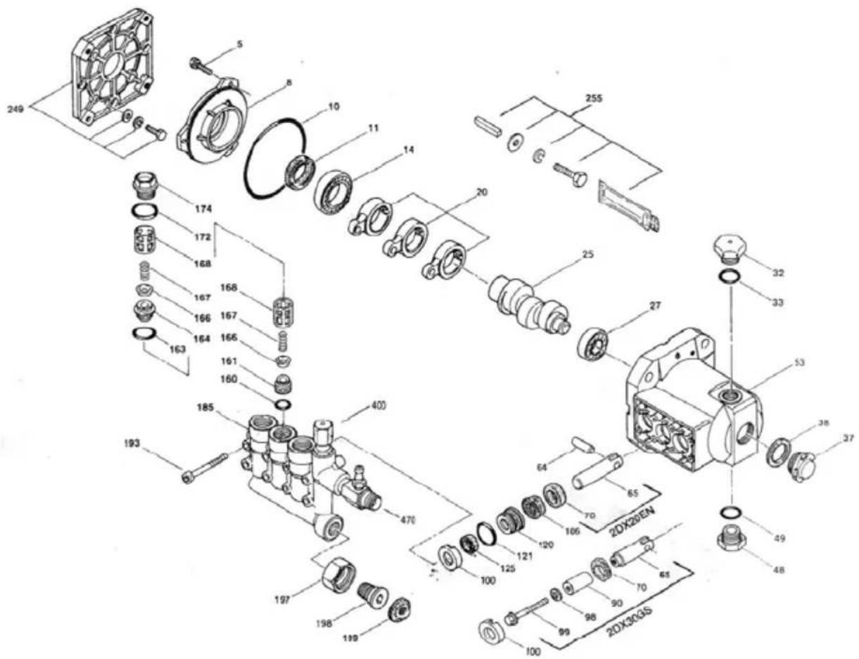
ITEM PART DESCRIPTION QTY.
5 817003 SCREW, HH W/ SW (M6x12) 3
8 46225 COVER, BEARING 1
10 14041 O-RING. BEARING COVER -70 1
11 55337 SEAL, OIL 1
14 14488 BEARING, BALL 1
20 46228 ROD, CONNECTING
25 542981 CRANKSHAFT (4.2mm) (3450)
543295 CRANKSHAFT (6.2mm) (3400) 1
27 13832 BEARING, BALL 1
3245690CAP,OIL FILLER 1
33 14179 O-RING, OIL FILLER CAP -70
37 43987 GAUGE, BUBBLE OIL
48 44842 PLUG, DRAIN (1/2" NPT) 1
49 14179 O-RING, DRAIN PLUG
53 542407 CRANKCASE
64 46229 PIN, RIST 3
65 542402 ROD, PLUNGER (2DX20E,2DX30GS)
46628 ROD, PLUNGER (2DX20EN,2DX30GNS) 3
70 47215 SEAL, OIL 3
90542403 PLUNGER (2DX30GS) 3
98 46730 WASHER, SEAL 3
99 542405 RETAINER, PLUNGER (M6x35)
100 46233 RETAINER, SEAL
106 48222 SEAL, LPS W/S-SPG
120 46436 CASE, SEAL
121 13976 O-RING, SEAL CASE
125 46240 SEAL, HPS W/S
160 13965 O-RING, INLET VALVE SEAT
161 46760 SEAT, INLET
163 19285 O-RING, SEAT
164 46761 SEAT, DISCHARGE
166 46764 VALVE 6
Cat 2DX Pump Breakdown
ITEM PART DESCRIPTION QTY.
167 46865 SPRING 6
168 543988 RETAINER, SPRING 6
172 11338 O-RING, PLUG 6
174 46759 PLUG, VALVE (M22x1.5) 6
185 542973 HEAD, MANIFOLD W/MODULAR UNLDR BODY 1
193 542406 SCREW, HSH (M6x60) 8
197 46488 FITTING, (3/8" NPT) 1
198 46487 NUT, SWIVEL (3/4") 1
19946489 SCREEN, INLET 1
249 30520 KIT, ADAPTOR MOUNT, STANDARD.GAS
46789 FLANGE 1
44843 SCREW, HH (5/16"-24UNFx20) 4
15845 LOCKWASHER (M8) 4
12489 WASHER, FLAT (M8) 4
255 30516 KIT, BOLT MOUNT, ELECTRIC/ GAS
34100 SCREW, HH (3/8"-16UNCx1-3/8") 4
30980 WASHER, FLAT (3/8") 4
30921 LOCKWASHER (3 / 8^ ) 4
6106 LUBRICANT, ANTI-SEIZE 1
34050 KEY (3/16x3/16x27 HD) 1
300 33053 KIT, SEAL (INCLDS:98,106,121,125)
310 33057 KIT VALVE 2
(INCLDS:160,161,163,164.166,167,168,172)
400 UNloader, MODULAR-SEE INDIVIDUAL PARTS 1
470 INJECTOR, CHEMICAL-SEE INDIVIDUAL PARTS 1
Seal Kit: 33053
Valve Kit: 33057
Identification Des Composantes
Accessories/Accessoires
Pump Oil (1L)
Small Dirt Killer Assembly
Petitboserotative
85.210.180
Gauge Kit
Gauge
85.305.001
Coupler & Plug (3/8")
Raccords (3/8")
85.400.201
Spray Nozzle Kit
Becs d'arrosage
85.210.045
Accessories/Accessoires

- Component Identification
- Before You Begin
- Safety Instructions
- WARNING
- Safety Instructions Continued
- General Warnings & Cautions
- GeneralWarnings & Cautions Continued
- Location,Warnings & Cautions
- Gas Engine Precautions
- A FIRE OR EXPLOSION CAN OCCUR RESULTING IN PERSONAL INJURY IF THE FOLLOWING INSTRUCTIONS ARE NOT FOLLOWED:
- Electric Motor Precautions
- Extension Chords
- Pump Precautions
- Pre-Operation Checklist
- Setup & Use
- Setup & Use Continued
- Operating Instructions
- Operating Instructions Continued
- Shutdown Instructions
- Winterize The Machine
- Preventive Maintenance
- Daily Checks
- Pressure Washer Troubleshooting
- Introduction
- Pressure Washer Troubleshooting Continued
- Cavitation
- Some Pressure Washer Problems
- If a Problem Occurs - Some Preliminary Checks
- More Troubleshooting Tips
- Problems With Detergent
- Most Frequently Asked Questions
- Gas Engine Troubleshooting
- Electric Motor Troubleshooting Continued
- Pump Troubleshooting
- Pump Troubleshooting Continued
- Pump Pressure Warranty
- Frame Assembly Instructions
- Single-Handle Frame
- Frame Assembly Instructions Continued
- Large Frame
- Stainless Steel Belt Drive Frame
- ITEM PART DESCRIPTION QTY.
- General EZ Pump Breakdown
- General TP Pump Breakdown
- Comet ZWD Pump Breakdown
- Comet AXD Pump Breakdown
- Comet VRX 2017V Pump Breakdown
- AR XMV Pump Breakdown
- ITEM PART DESCRIPTION QTY
- Cat 5DX Pump Breakdown
- Cat 2DX Pump Breakdown
- Identification Des Composantes
- Accessories/Accessoires
Brand : Lavor
Model : PWR4000
Category : Pressure washer