
K100HERTX - Range hood BERTAZZONI - Free user manual and instructions
Find the device manual for free K100HERTX BERTAZZONI in PDF.
| Product type | Decorative hood |
| Brand | Bertazzoni |
| Model | K100HERTX |
| Use | Extraction of cooking fumes and steam, domestic use |
| Installation | Wall-mounted, with telescopic chimney |
| Operating mode | External extraction or internal recirculation |
| Power supply | 220-240 V / 50-60 Hz |
| Number of speeds | 4 (including 1 booster) |
| Booster function | Yes (4th speed, timed 7 min, automatic return to 3rd speed) |
| Automatic shut-off | Yes, 15 min timer (speed 1, 2 or 3) |
| Lighting | LED 2 x 1.5 W |
| Grease filter | Metallic, dishwasher-safe (short cycle, low temperature) |
| Charcoal filter | For recirculation mode, replacement or regeneration every 2 months |
| Maintenance | Monthly cleaning of grease filter; do not use alcohol or abrasives |
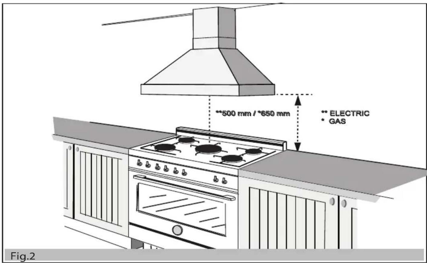
| Minimum distance (gas) | 650 mm between cooking surface and hood |
| Minimum distance (electric) | 500 mm |
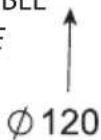
| Exhaust duct diameter | ∅150 mm or ∅120 mm (according to connection flange) |
| Included accessories | Fixing screws, wall plugs ∅8, bracket, drilling template |
| Safety | Disconnect before cleaning; do not use without filters; avoid open flames |
| Repairability | Replacement of LEDs by technical support service |
| Weight | Approximately 12 kg (estimated) |
Frequently Asked Questions - K100HERTX BERTAZZONI
User questions about K100HERTX BERTAZZONI
0 question about this device. Answer the ones you know or ask your own.
Ask a new question about this device
Download the instructions for your Range hood in PDF format for free! Find your manual K100HERTX - BERTAZZONI and take your electronic device back in hand. On this page are published all the documents necessary for the use of your device. K100HERTX by BERTAZZONI.
USER MANUAL K100HERTX BERTAZZONI
Installations instructions
DUNSTABZUGHAUBE
natural_image
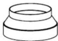
Technical line drawing of a conical exhaust chimney with mounting flanges (no text or symbols)
K120HERTX
K100HERTX
K90HERTX
NELL'IMBALLO
INSIDE PACKAGING
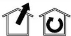
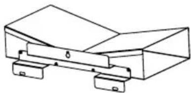
CAPPA RANGE HOOD (x1)
D - (x1)
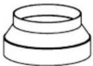
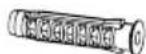
RIDUZIONE ∅150/120
ADAPTER ∅150/120
natural_image
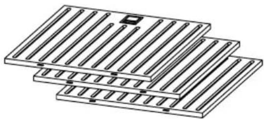
Stack of three identical rectangular panels with vertical slots and a small square top (no text or symbols)F - (x^*)
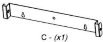
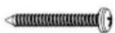
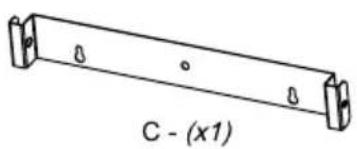
STAFFA TUBI
PIPE BRACKET
*FILTRI ANTIGRASSO/GREASE FILTERS
*(Q.tà in base al modello acquistato
*(Q.ty according to the mod. purchased)
CONTENUTO DEL SACCHETTO
CONTENTS OF THE BAG
T (X6) - TASSELLI ∅8 / WALL ANCHORS ∅8
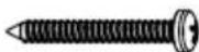
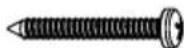
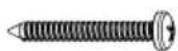
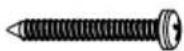
W (X6) - VITE 4,8X40 / SELF TAPPING SCREWS 4,8X40

V (X2) - VITE M4X10 / SCREWS M4X10

DA ACQUISTARE
TO BUY
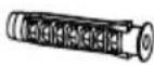
natural_image
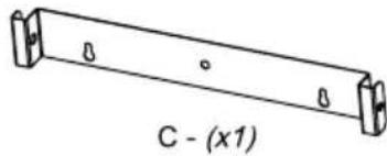
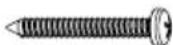
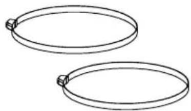
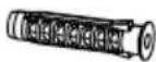
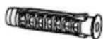
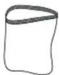
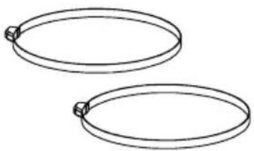
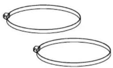
Two identical oval-shaped rings with evenly spaced small protrusions, no text or symbols present.FASCETTE STRINGITUBO
HOSE CLAMPS
natural_image
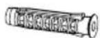
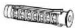
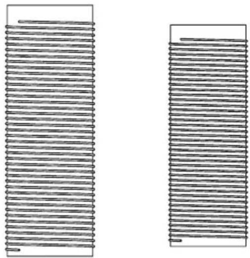
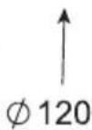
Two identical cylindrical electronic components with parallel leads, shown from different angles (no text or symbols)∅ 150 ↑
(Recommended)
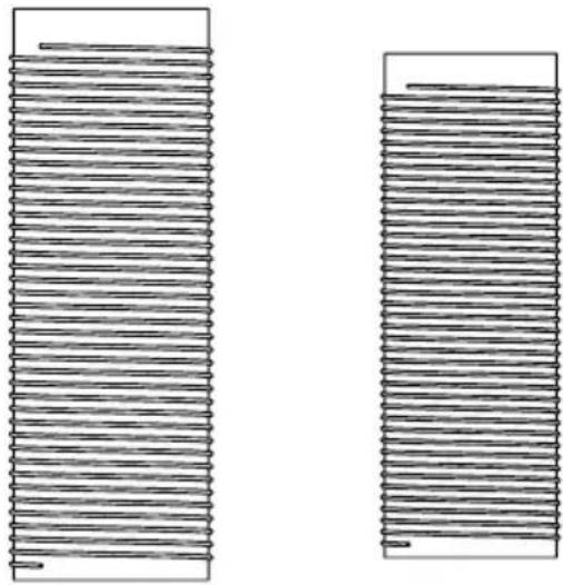
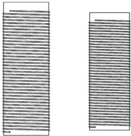
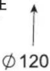
TUBO ESTENSIBILE
EXTENDABLE PIPE
∅ 120

DA ACQUISTARE KIT FILTRANTE
TO BUY RECIRCULATING KIT
opzionale /on request
-Cappa 900mm-1000mm: code 901515
Hood 900mm-1000mm
-Cappa 1200mm: code 901516
Hood 1200mm
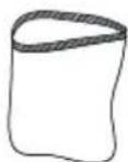
FLANGIA ∅150
FLANGE ∅150
natural_image
Simple line drawing of a cylindrical object with a flared rim (no text or symbols)(x1)
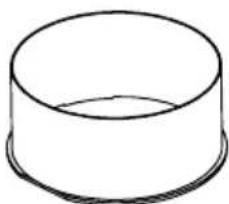
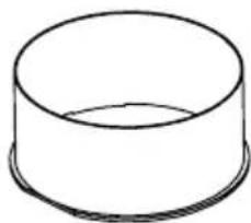
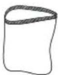
DEVIATORE DI FLUSSO
FLOW DEFLECTOR

natural_image
Simple line drawing of a mechanical bracket or clamp device (no text or symbols)(x1)
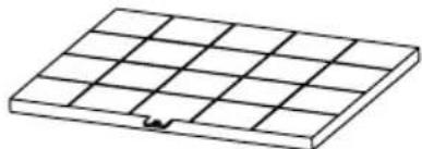
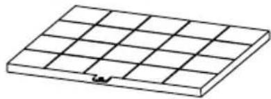
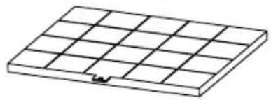
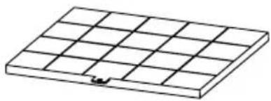
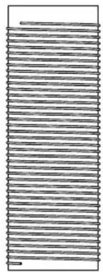
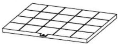
FILTRO AL CARBONE
CHARCOAL FILTER

natural_image
Isometric line drawing of a grid-patterned rectangular plate with a small notch at the bottom (no text or symbols)(x1)
T (X3) - TASSELLI ∅8 / WALL ANCHORS ∅8
W (X3) - VITE 4,8X40 / SELF TAPPING SCREWS 4,8X40
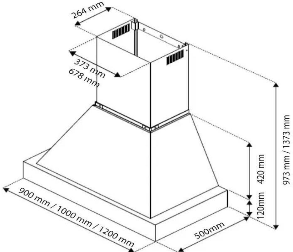
Fig.1


natural_image
Illustration of a handheld electric drill and a pair of scissors cutting through a pencil, no text or symbols present.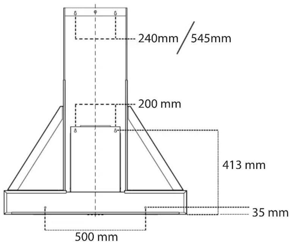
Fig.4
natural_image
Technical line drawing of a mechanical assembly with a central circular component and support structures (no text or symbols)Fig.5

Fig.6

flowchart
graph TD
    A["1"] --> B["1"]
    C["3"] --> D["2"]
    E["□"] --> F["1"]
    G["■"] --> H["1"]
    I["4"] --> J["1"]
    B --> K["↓"]
    D --> L["↓"]
    F --> M["↓"]
    H --> N["↓"]
    J --> O["↓"]

natural_image
Five circular icons representing light, minus sign, fan, plus sign, and clock symbols (no text or labels)Fig.8
IT AVVERTENZE GENERALI
Strictly follow the instructions in this manual. We shall not be held liable for any inconvenience, damage or fire caused to the appliance as a result of failure to follow the instructions in this manual. The hood has been designed to extract cooking fumes and vapors and is intended for domestic use only. Your hood may differ in appearance from the ones shown in the drawings in this manual, yet instructions for use, maintenance and installation do apply to all models.
- It is important to retain all manuals provided with the appliance for future reference. In the event of sale, transfer or removal, make sure to keep them with the appliance.
- Please read these instructions carefully, they contain important safety, installation, and operating information.
- Do not carry out any electrical or mechanical changes to the product or the exhaust ducts.
- Check integrity of the hood before pro - ceeding with the installation. In case the appliance is damaged or non-compliant, contact the retailer and do not continue with the installation.
Note: Some parts/components and/or features of the appliance are accessories which are supplied/available only for some models, or need to be purchased separately as optional.
SAFETY
- Before performing any cleaning or maintenance operation, disconnect the hood from power supply by removing the plug or turning off the main switch of the house.
- Use all necessary personal protective equipment (PPE) for all installation and maintenance operations.
- The appliance can be used by children of 8 years of age or older and by persons with reduced physical, sensory or mental abilities, or lack of experien-
ce and knowledge, provided they are supervised or have received instructions concerning the safe use of the appliance and have an understanding of the hazards involved.
• Children should be supervised to make sure they do not play with the appliance.
- Cleaning and maintenance operations shall not be carried out by children without supervision.
- The room shall be sufficiently ventilated when the kitchen hood is used simultaneously with other appliances fed by gas or other fuels.
- The kitchen hood needs regular cleaning, both in its internal and external parts (AT LEAST ONCE A MONTH), and the maintenance instructions provided for in this manual shall be followed.
- Failure to follow the instructions for cleaning the hood and replacing/ cleaning the filters may result in a fire hazard.
- It is strictly forbidden to do open flame cooking under the hood.
- For lamp replacement, follow the instructions given in the lamp maintenance/replacement section of this manual.
- Open flame cooking can damage filters/ grids and can cause fires, so it must be avoided under all circumstances.
- Frying shall always be supervised in order to prevent overheated oil from catching fire.
CAUTION:
When the hob is on, the accessible parts of the hood can become hot.
INSTALLATION
- The minimum distance between the support surface of containers on the cooking device and the lowest part of the kitchen hood shall not be lower than the ones indicated in the figure (s) relating to the installation for the different types of cooking devices (Gas hob: 650mm / Electric hob: 500mm). If the installation instructions of the gas hob require a greater distance, this must be taken into account (Fig. 2).
- Do not connect the appliance to the mains until installation is fully completed.
- As for the technical and safety measures to be adopted for the discharge of fumes, strictly comply with the provisions of the regulations specified by the competent local authorities.
- Extracted air shall not be conveyed into a duct used for the discharge of fumes produced by appliances burning gas or other fuels.
- Do not use or leave the hood without its lamps properly fitted, as it may result in potential electric shock risk.
- NEVER use the hood without its grid/ filters properly fitted!
- The hood should NEVER be used as a support surface unless specifically indicated. The maximum total weight of any objects positioned or hung on the hood (where applicable), must not exceed 1.5Kg.
- For installation, use only the fixing screws supplied with the appliance or, in case they are not supplied, purchase the correct type of screws.
- Use screws with the correct length specified in the documentation.
- Contact the authorized service center or similar qualified personnel in case of doubts.
CAUTION!
Failure to install screws and fixing devices in accordance with these instructions may result in electrical risk.
Do not use the appliance with a programmer, timer, separate remote control, or any other device that activates automatically.
ASSEMBLY
Before starting installation:
- Check that the product purchased is of a suitable size for the area where it is to be installed.
- Check that (for transportation purposes) there is no material inside the hood (e.g. bags with screws, warranties, etc.), which needs to be removed and stored for future use.
Follow the installation instructions specified below:
- The appliance shall be installed at the required distance from the cooking surface (Gas hob: 650mm / Electric hob: 500mm) - (Fig. 2).
- Remove the three metal grease filters (Fig.3-B).
- Drill the holes on the wall according to the template provided (see Fig. 4).
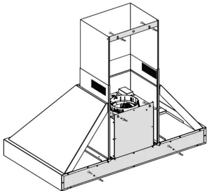
- Use the inserts to fix the hood (Fig. 5).
- Hang the hood on the wall (A), and secure it with the screws (C) (Fig.6).
- Position the bracket (D) and secure it to the wall (B) (Fig. 6).
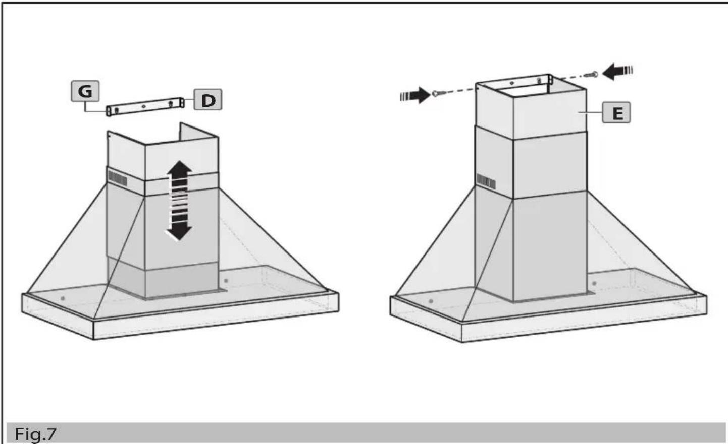
- Adjust the telescopic chimney elements and secure it to the bracket (D) (Fig.7).
CAUTION!
Heavy-weight product: hood handling and installation should be carried out by at least two people or more.
ELECTRIC CONNECTION
The mains voltage shall be the same as the voltage shown on the rating label found inside the hood. If the hood is equipped with a plug, connect the hood to a socket compliant with current regulations, which can be easily reachable even after installation. If the hood is not equipped with a plug (direct connection to the mains) or the plug is not located in an easily accessible area, even after installation, use a standard-compliant two-pole switch that ensures complete disconnection from the mains under overvoltage category III, in accordance with current installation rules and norms.
CAUTION!
Before reconnecting the hood circuit to power supply and verifying proper operation, always check that the mains lead/cable has been fitted correctly. The hood is equipped with a special power cord; if the cord is damaged, send a request to the technical service department.
HOW TO USE THE APPLIANCE
Tips for the hood proper correct use aimed at reducing environmental impact:
Turn on the hood at minimum speed when you start cooking, and leave it on for a few minutes even after cooking has been completed. Increase the speed only in the case of large amounts of fumes and vapors, using the booster function only when absolutely necessary. To keep the odor reduction system efficient, replace the charcoal filter(s) as needed. To keep the grease filter efficient, clean it when necessary. Use a ducting system of the maximum diameter indicated in this manual, in order to optimize efficiency and minimize noise. The hood has been designed to be used either in the extraction mode with air discharged outside the room, or in the recycling mode with air internal recirculation
EXTRACTION MODE
Vapors are discharged to the outside through an exhaust pipe fixed to the connecting flange.
CAUTION!
The exhaust pipe is generally not supplied with the appliance and must be purchased separately. The exhaust pipe diameter should ideally be the same as the diameter of the connecting ring (connecting flange) (∅150/∅120 - page 3).
CAUTION!
If the hood is equipped with charcoal filter(s), they must be removed in the case the hood is operated in the extraction mode.
Connect the hood to pipes and wall outlets having the same diameter as the air outlet (connecting flange). The use of pipes and wall outlets with a smaller diameter will result in a decrease in extraction performance and a high increase in noise level. We therefore decline all liability in this regard.
Use a pipe of the necessary length. In horizontal sections, the pipe should have a slight slope (approx. 10%) to better convey the air to the outside of the room.
- Use a duct with as few bends as possible (maximum bend angle: ≤90°).
- Avoid abrupt changes in duct cross-section.
Only for Germany: When the cooker hood and appliances powered by energy other than electricity are operating simultaneously, the negative pressure in the room shall not exceed 4 Pa (4 x 10⁻⁵ bar).
RECYCLING MODE
The air extracted is ‘degreased’ and ‘deodorized’ before being conveyed back into the room. To use the hood in this mode, you need to fit an additional filtering system based on charcoal filters, in case your hood is not already equipped with it, by simply following the instructions given in the recirculating kit (page 3).
CONTROLS


- ON: light ON
OFF: light OFF - The hood motor is switched on and off. When switched on, the hood starts working at first speed.
- ☑ The motor speed is decreased.
The motor speed is increased. This hood model has 4 speeds. The 4th speed is timed: the motor will automatically switch to 3rd speed after 7 minutes of operation. - It allows automatic switching off of the hood after 15 minutes of operation at 1,2,3 speed (flashing light key).
LIGHTING
The hood is equipped with a lighting system based on LED technology (2 LEDs of 1.5W), which ensures optimal lighting and a duration up to 10 times longer than traditional lamps, thus allowing for considerable energy savings.
For lamp replacement, please contact the technical assistance service.
CLEANINGANDMAINTENANCE
Clean the hood using ONLY a cloth dampened with neutral liquid detergent.
DO NOT USE ANY TOOLS OR OTHER INSTRUMENTS FOR CLEANING OPERATIONS!
Avoid using products containing abrasive substances.
DO NOT USE ALCOHOL!
Grease Filter
Captures grease particles produced during cooking. It must be cleaned once a month, using non-aggressive detergents; it can be hand washed or washed in the dishwasher at low temperatures and on a short cycle. The metal grease filter may fade when washed in the dishwasher, yet this will in no way not affect its filtering efficiency
Charcoal Filter (For recycling version only)
Retains unpleasant cooking odors. The charcoal filter must be replaced (or regenerated - depending on the model: supplied/optional every two months.
DISPOSAL OF HOUSEHOLD APPLIANCE
This appliance is designed, tested and manufactured in compliance with current regulations.
This appliance is marked in accordance with the European Directive 2012/19 / EC, Waste Electrical and Electronic Equipment (WEEE). By ensuring this product is disposed of correctly, users will help prevent potential negative consequences for the environment and human health.
The symbol on the product or the related documentation indicates that this product shall not be treated as household waste, but shall be handed over to the appropriate collection point for the recycling of electrical and electronic equipment. Dispose of it according to your local waste disposal regulations. For more information on the treatment, recovery and recycling of this appliance, contact your local city office, your household waste collection service or the shop where you purchased the appliance.
VERPACKUNGSINHALT
INSIDE PACKAGING
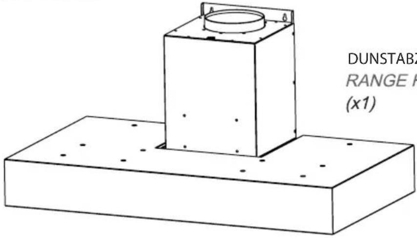
DUNSTABZUGSHAUBE RANGE HOOD (x1)
D - (x1)
REDUZIERUNG ∅150/120
ADAPTER ∅150/120
ROHRHALTERUNG
PIPE BRACKET

natural_image
Stack of three parallel metal sheets with vertical grooves and small connectors (no text or symbols)natural_image
Two identical oval-shaped rings with small protrusions, no text or symbols presentSCHLAUCHSCHELLEN
HOSE CLAMPS
natural_image
Two identical cylindrical structures with parallel lines, no text or symbols visible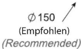
natural_image
Simple line drawing of a cylindrical object with a flared rim (no text or symbols)(x1)
UMLENKSTÜCK KOHLEFILTER
FLOW DEFLECTOR
natural_image
Simple line drawing of a mechanical or architectural component with two base blocks and a central support (no text or symbols)(x1)
CHARCOAL FILTER
natural_image
Isometric view of a grid-patterned rectangular panel with a small notch at the bottom (no text or symbols)(x1)
T (X3) - DÜBEL ∅8 / WALL ANCHORS ∅8
BLECHSCHRAUBEN 4,8X40 / SELF TAPPING SCREWS 4,8X40W (X3)
natural_image
Stack of three parallel rectangular panels with vertical slots, no text or symbols visiblenatural_image
Two identical oval-shaped rings with evenly spaced small protrusions, no text or symbols present.COLLIER DE SERRAGE
HOSE CLAMPS

natural_image
Pure electrical circuit lines without any symbols
natural_image
Pure electrical circuit lines without any symbols
(Recommended)
TUYAU EXTENSIBLE
EXTENDABLE PIPE

KIT FILTRANT À ACHETER
TO BUY RECIRCULATING KIT
optionnel /on request
-Hotte 90mm: code 901515
Hood 90mm
-Hotte 120mm: code 901516
Hood 120mm
BRIDE ∅150
FLANGE ∅150
natural_image
Simple line drawing of a cylindrical object with a flared rim (no text or symbols)(x1)
DÉVIATEUR DE FLUX FILTRE À CHARBON
FLOW DEFLECTOR

natural_image
Technical line drawing of a mechanical bracket or clamp assembly (no text or symbols)(x1)
CHARCOAL FILTER
natural_image
Simple line drawing of a grid-patterned rectangular panel with a small notch at the bottom (no text or symbols)(x1)
T (X3) - CHEVILLES ∅8 /WALL ANCHORS ∅8
W (X3) - VIS TARAUDEUSE 4,8X40 / SELF TAPPING SCREWS 4,8X40
FR
AVERTISSEMENTS GÉNÉRAUX
natural_image
Stack of three parallel metal sheets with vertical slots and a small square component on top (no text or symbols)F - (x^*)
* FILTROS ANTI GRASA / GREASE FILTERS
* (cant. El modelo comprado)
*(Q.ty according to the mod. purchased)
CONTENIDO DEL PAQUETE
CONTENTS OF THE BAG
T (X6) - TACOS ∅8 / WALL ANCHORS ∅8
W (X6) - TORNILLOS 4,8X40 / SELF TAPPING SCREWS 4,8X40

V (X2) - TORNILLOS M4X10 / SCREWS M4X10

PARA COMPRAR
TO BUY
natural_image
Two identical oval rings with evenly spaced small protrusions, no text or symbols present.ABRAZADERA DE MANGUERA
HOSE CLAMPS
natural_image
Two identical vertical panels showing parallel coiled lines, no text or symbols present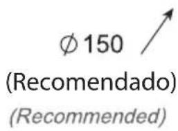
MANGUERA EXTENSIBLE
EXTENDABLE PIPE

PARA COMPRAR KIT FILTRANTE
TO BUY RECIRCULATING KIT
opcional /on request
-Campana 90mm: code 901515 Hood 90mm
-Campana 120mm: code 901516 Hood 120mm
natural_image
Simple line drawing of a cylindrical object with a flared rim (no text or symbols)(x1)
FLOW DEFLECTOR

natural_image
Technical line drawing of a mechanical bracket or support structure (no text or symbols)(x1)
CHARCOAL FILTER
natural_image
Isometric view of a grid-patterned rectangular panel with a small black mark on one side (no text or symbols)(x1)

T (X3) - TACOS ∅8 / WALL ANCHORS ∅8
W (X3) - TORNILLOS 4,8X40 / SELF TAPPING SCREWS 4,8X40
ES
natural_image
Simple line drawing of a rectangular object with four corner holes and a label 'C - (x1)' below (no other text or symbols)FÄSTJÄRN RÖR
PIPE BRACKET
natural_image
Stack of three parallel rectangular panels with vertical slots, no text or symbols visibleF - (x^*)
* FETTFILTER / GREASE FILTERS
* (mängd beroende på inhandlad modell)
*(Q.ty according to the mod. purchased)
PÅSENS INNEHÅLL
CONTENTS OF THE BAG
T (X6) - PLUGGAR ∅8 / WALL ANCHORS ∅8
W (X6) - SKRUV 4,8X40 / SELF TAPPING SCREWS 4,8X40

V (X2) - SKRUV M4X10 / SCREWS M4X10

BEHÖVER INHANDLAS
TO BUY
natural_image
Two identical wire rings with circular ends, no text or symbols presentRÖRHÅLLARE
HOSE CLAMPS

natural_image
Two identical cylindrical structures with parallel lines, no text or symbols visible

FILTRERINGSKITT BEHÖVER
INHANDLAS
TO BUY RECIRCULATING KIT
Tillbehör / on request
FLÄNS ∅150
FLANGE ∅150
natural_image
Simple line drawing of a cylindrical object with a flared rim (no text or symbols)(x1)
FLÖDESAVLEDARE KOLFILTER
FLOW DEFLECTOR

natural_image
Technical line drawing of a mechanical clamp or bracket assembly (no text or symbols)(x1)
-Spisfläkt 90mm: code 901515 Hood 90mm
-Spisfläkt 120mm: code 901516 Hood 120mm
CHARCOAL FILTER
natural_image
Isometric view of a grid-patterned rectangular panel with a small black mark on one side (no text or symbols)(x1)
T (X3) - PLUGGAR ∅8 / WALL ANCHORS ∅8
W (X3) -
SELF TAPPING SCREWS 4,8X40SKRUV 4,8X40 /
SV
ALLMÄNNA VAR- NINGSFÖRESKRIFTER
natural_image
Stacked rectangular panels with parallel lines and a small square marker on top (no text or symbols)F - (x*)
BEUGEL BUIZEN
PIPE BRACKET
* VETFILTERS / GREASE FILTERS
* (Aantal afhankelijk van aangekocht model)
*(Q.ty according to the mod. purchased)
INHOUD VAN DE ZAK
CONTENTS OF THE BAG

T (X6) - PLUGGEN ∅8 / WALL ANCHORS ∅8
W (X6) - ZELFTAPPENDE SCHROEVEN 4,8X40 / SELF TAPPING SCREWS 4,8X40

V (X2) - TORNILLOS M4X10 / SCREWS M4X10

AAN TE KOPEN
TO BUY

natural_image
Two identical oval-shaped rings with evenly spaced small dots at each end (no text or symbols)HOSE CLAMPS
natural_image
Pure electrical circuit lines without any symbols
natural_image
Pure electrical circuit lines without any symbols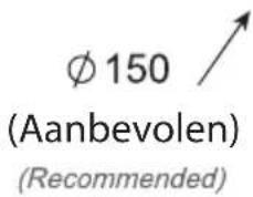
EXTENDABLE PIPE

AAN TE KOPEN FILTERKIT
TO BUY RECIRCULATING KIT
-Hood 90mm: code 901515
-Hood 120mm: code 901516
optioneel / on request
FLENS ∅150 OMLEIDER
FLANGE ∅150

natural_image
Simple line drawing of a cylindrical object with rounded edges (no text or symbols)(x1)
FLOW DEFLECTOR

natural_image
Pure technical line drawing of a mechanical assembly without any text, numbers, or symbols(x1)
KOOLSTOFFILTER
CHARCOAL FILTER
natural_image
Isometric line drawing of a grid-patterned rectangular panel with a small protrusion at the bottom (no text or symbols)(x1)

T (X3) - PLUGGEN ∅8 / WALL ANCHORS ∅8

W (X3) - ZELFTAPPENDE SCHROEVEN 4,8X40 / SELF TAPPING SCREWS 4,8X40
NL
ALGEMENE WAARSCHUWINGEN


- IT AVVERTENZE GENERALI
- SAFETY
- CAUTION:
- INSTALLATION
- CAUTION!
- ASSEMBLY
- ELECTRIC CONNECTION
- HOW TO USE THE APPLIANCE
- Tips for the hood proper correct use aimed at reducing environmental impact:
- EXTRACTION MODE
- RECYCLING MODE
- CONTROLS
- LIGHTING
- CLEANINGANDMAINTENANCE
- Grease Filter
- Charcoal Filter (For recycling version only)
- DISPOSAL OF HOUSEHOLD APPLIANCE
- FR
- AVERTISSEMENTS GÉNÉRAUX
- ES
- SV
- ALLMÄNNA VAR- NINGSFÖRESKRIFTER
- NL
- ALGEMENE WAARSCHUWINGEN
Brand : BERTAZZONI
Model : K100HERTX
Category : Range hood