
321S15 - Electric mower HUSQVARNA - Free user manual and instructions
Find the device manual for free 321S15 HUSQVARNA in PDF.

| Product Type | Thermal Backpack Sprayer |
| Brand | Husqvarna |
| Model | 321S15 |
| Spray Tank Capacity | 15 L |
| Fuel Tank Capacity | 0.6 L |
| Engine Type | Air-cooled 2-stroke gasoline, single cylinder |
| Displacement | 25.4 cm³ |
| Maximum Power | 0.75 kW at 7,000 rpm |
| Idle Speed | 3,000 rpm |
| Pump Type | Plunger |
| Working Pressure | 1.5 to 3.0 MPa |
| Maximum Pressure | 3.5 MPa |
| Maximum Flow Rate | 7 L/min |
| Dimensions (L × W × H) | 395 × 370 × 556 mm |
| Empty Weight | 9.2 kg |
| Fuel/Oil Mix Ratio | 25:1 or 50:1 (Husqvarna oil) |
| Spark Plug | LD L7T or CDK L8RTC, gap 0.6-0.7 mm |
| Recommended Safety Equipment | Helmet, goggles, mask, gloves, boots, protective clothing |
| Routine Maintenance | Clean air and fuel filters every 25 h, drain tank before storage |
| Original Parts | Use exclusively Husqvarna parts |
Frequently Asked Questions - 321S15 HUSQVARNA
User questions about 321S15 HUSQVARNA
0 question about this device. Answer the ones you know or ask your own.
Ask a new question about this device
Download the instructions for your Electric mower in PDF format for free! Find your manual 321S15 - HUSQVARNA and take your electronic device back in hand. On this page are published all the documents necessary for the use of your device. 321S15 by HUSQVARNA.
USER MANUAL 321S15 HUSQVARNA
natural_image
Close-up of an orange car body with a 3D logo on the front wheel (no visible text or symbols)Operator's manual Manual do utilizador Manual de usuario Manuel d'utilisation
321S15 321S25

natural_image
Simple line drawing of an open book enclosed in a circle (no text or symbols)Please read the operator's manual carefully and make sure you understand the instructions before using the machine. Leia atentamente as instruções do manual do utilizador e certifique-se de que compreende o seu conteúdo antes de utilizar a máquina. Lea detenidamente el manual de usuario y asegúrese de entender su contenido antes de utilizar la máquina. Lisez attentivement et assimilez le manuel d'utilisation avant d'utiliser la machine.
English (2-21) Portuguese (22-41) Spanish (42-64) French (65-87)
Symbols
Read owner's manual before operating this machine.
Wear protective headgear, protective goggles, ear muffs and protective mask.
Wear rubber boots.
Wear protective clothing.
Wear rubber gloves.
Electric shock
Hot surface
High pressure injection
Keep a safe distances.


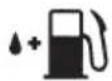
The port to refuel the MIX GASO-LINE
The direction to close the choke
The direction to open the choke
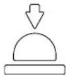
Primer


Never modify your machine.
We won't warrant the machine, if you use the remodeled power sprayer or if you don't observe the proper usage written in the manual.
Contents
KEY TO SYMBOLS
Symbols....2
CONTENTS
Note the following before starting: 3
INTRODUCTION
Dear Customer, 4
WHAT IS WHAT? 5
SAFETY
For safe operation 6
ASSEMBLY
To assemble the sprayer 9
To connect the spray hose assembly and the pump outlet ....9
To connect the spray hose assembly and spray rods ....9
To install and adjust the straps assembly with the unit 9
Checklist before starting the sprayer 9
FUEL
To mix the fuel 10
To fuel the unit ....10
CHEMICAL FILLING
Procedure for fi lling 11
OPERATION
To start the engine 11
To stop the engine 13
To spray 13
Spraying procedure 13
Cleaning after completion of spraying ..... 13
MAINTENANCE
To check the air cleaner 14
To check the fuel filter 14
To check the spark plug 14
To adjust the engine speed 14
To check spray nozzle ....15
To check the pump oil level 15
To check the muffler 16
To check the air cooling fan ....16
To replace the gear oil 16
To check the grease cups 17
DISPOSAL AND STORAGE
Disposal....18
Storage....18
TROUBLESHOOTING
TECHNICAL DATA
Note the following before starting:
Please read the operator's manual carefully.

Warning labels bearing the ▲ mark on the product and in this Manual refer to important safety matters. Please familiarize yourself with them and observe them well.
If a warning label on the product becomes soiled or detached, please order a replacement label from your dealer and attach it in the requisite place.
PRECAUTIONS
In this Operator's Manual, precautions that are considered to be particularly important are indicated as follows.
WARNINGS IN THE MANUAL

WARNING
Failure to observe the precaution may result in the risk of death or serious injury.

IMPORTANT
Failure to observe the precaution may result in damage or malfunction of the product.

NOTE
Other additional explanations that may be of use when operating the product.
INTRODUCTION
Dear Customer,
Congratulations on your choice to buy a Husqvarna product! Husqvarna is based on a tradition that dates back to 1689, when the Swedish King Karl XI ordered the construction of a factory on the banks of the Husqvarna River, for production of muskets. The location was logical, since water power was harnessed from the Huskvarna River to create the waterpowered plant. During the more than 300 years in existence, the Husqvarna factory has produced a lot of different products, from wood stoves to modern kitchen appliances, sewing machines, bicycles, motorcycles etc. In 1956, the first motor driven lawn mowers appeared, followed by chain saws in 1959, and it is within this area Husqvarna is working today.
Today Husqvarna is one of the leading manufacturers in the world of forest and garden products, with quality as our highest priority. The business concept is to develop, manufacture and market motor-driven products for forestry and gardening, as well as for the building and construction industry. Husqvarna's aim is also to be at the front edge for ergonomics, usability, security and environmental protection. That is the reason why we have developed many different features to add to our products within these areas.
We are convinced that you will appreciate with great satisfaction the quality and performance of our product for a very long time to come. The purchase of one of our products gives you access to professional help with repairs and service whenever this may be necessary. If the retailer who sells your machine is not one of our authorised dealers, ask for the address of your nearest service workshop.
It is our wish that you will be satisfied with your product and that it will be your companion for a long time. Think of this operator's manual as a valuable document. By following its content (usage, service, maintenance, etc), the life span and the second-hand value of the machine can be extended. If you sell this machine, make sure that the operator's manual is passed on to the buyer.
Thank you for using a Husqvarna product.
Husqvarna AB has a policy of continuous product development and therefore reserves the right to modify the design and appearance of products without prior notice.
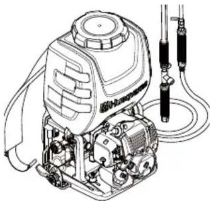
WHAT IS WHAT?
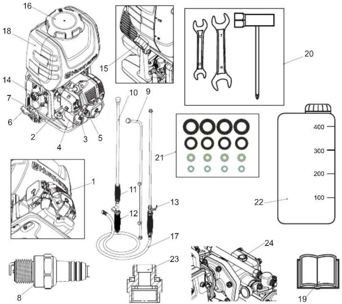
What is what?
1 Primer 13 Cock valve
2 Air cleaner cover 14 Pressure regulating dial
3 Choke lever 15 Drain cap
4 Fuel tank 16 Sprayer tank cap
5 Starter knob 17 Hose assembly
6 Throttle lever 18 Spray tank
7 Stop switch 19 OM
8 Spark plug 20 Assembly tools
9 3-nozzle spray rod 21 Spare parts
10 Single nozzle spray rod 22 Fuel oil mixing tank
11 Front handle 23 ISO nozzle adapter
12 Rear handle 24 Decal
SAFETY
For safe operation
Before using this product, please read this Operator's Manual thoroughly to ensure correct operation. The following are precautions that should be observed in order to use the product smoothly. Elsewhere in the Manual, the ▲ warning mark is used to bring your attention to these precautions.

Before using the product
- This product has been designed mainly for the purpose of spraying pest control chemicals and weedkillers. Please do not use it for any other purpose, as this may cause unforeseen accidents.
- Since this product uses agricultural chemicals that require careful operation, misuse can be dangerous. Do not use this product when tired or otherwise in poor physical condition, or when you may be unable to judge correctly or operate accurately, such as after taking cold relief medicines or drinking alcohol. Also, children or persons who are unable to understand the contents of this Manual should under no circumstances be permitted to use the product.

natural_image
Cartoon illustration of a boy holding a large bag with a no-smoking symbol overlay (no text or symbols present)
- The engine exhaust gas contains toxic carbon monoxide. Please do not use the product indoors, in vinyl houses or tunnels, or in other poorly ventilated places.

- Do not use this product in the following cases.
- When the product could fall over or in other situations when it is difficult to hold or operate.
- After sunset or at other times when eyesight is poor and the safety of the spraying area is diffi cult to ascertain.
- In worsening weather (rain, fog, strong wind, lightning, etc.)

natural_image
Cartoon illustration of a worker in a hard hat pointing forward with raindrops falling (no text or symbols)- When using for the first time, before commencing actual spraying please receive guidance in operating the product from a person with adequate experience.
- Fatigue reduces powers of concentration and increases the risk of accidents. When planning work, please allow ample time, setting a limit of 30-40 minutes for single spraying sessions and breaks of 10-20 minutes in between. Also, do not spray for more than 2 hours in any one day.

natural_image
Cartoon illustration of a person sitting on a bench with steam rising (no text or symbols)- Please take good care of this Operator's Manual and refer to it for additional information from time to time.
- When selling or lending this product, it should be accompanied by this Operator's Manual.
WARNING
- Check to see if the shock-absorbing rubber mount has become cracked or otherwise damaged. Note that failing to replace this rubber mount when it has become cracked or damaged may cause the engine to come loose from its frame during use, thus resulting in possible serious bodily injury.
- If cracked, be sure to replace without delay.
natural_image
Technical line drawing of a mechanical assembly with no visible text or symbols
WARNING
-
If you don't observe the working time, or working manner, Repetitive Stress Injury (RSI) could occur. If you feel discomfort, redness and swelling of your fingers or any other part of your body, see a doctor before getting worse.
-
To avoid noise complaints, in general, operate product between 8 a.m. and 5 p.m. on weekdays and 9 a.m. to 5 p.m. on weekends.
IMPORTANT
Check and follow the local regulations as to sound level and hours of operations for the product.
Precautions before spraying
- Make sure you have the correct protective clothing, headgear, rubber gloves and boots, a protective mask, goggles, a towel, protective cream, etc., to prevent chemicals from coming into contact with your skin or entering your lungs. When spraying, please wear this protective gear to prevent any risk of injury.


- Protective headgear
- Protective goggles
- Protective mask
- Rubber boots
- Ear muffs
- Neck covering
- Protective clothing
- Rubber gloves
-
Protective clothing
-
Please store chemicals in a locked storage box, locker, or other safe place out of the reach of children.
- Carefully read the instructions for using the chemicals, and familiarize yourself with the level of toxicity, method of use, etc.
- Please pay all due consideration to the area in which you will be spraying, to ensure that you do not pollute the water supply, rivers, lakes, ponds, etc., or cause any damage to residents, passers-by, livestock, etc.
- Prepare yourself physically on the day before spraying, by for example cutting down on alcoholic beverages or late-night work.
Do not allow children, animals, etc., to enter the chemical spraying area.

- Before spraying, please prepare fully by inspecting sprayer nozzles and checking for abnormalities such as loose screws or spray hose connections, fuel leaks, defective or broken fluid gaskets, or damage to the carrying band.
Precautions when transporting chemicals
- When transporting chemicals, please handle with care to ensure that there is no spillage of chemicals from torn bags, broken bottles, or loose stoppers.
- Do not carry chemicals in the same container as food.
Precautions when transporting the sprayer
- Do not transport the sprayer while it has chemicals or fuel in the tank, as these could leak out as a result of impact during transportation.
- When transporting in a vehicle, please use a rope or similar to fix the sprayer firmly to the cargo trailer in an upright position. Please do not transport by bicycle or motorbike, as this is dangerous.
WARNING
- If you must move the sprayer in a short distance by your hands, please use the handles on both sides of the tank to move it.
Precautions concerning fuel
WARNING
Taking the following precautions, will lessen the risk of fi re:
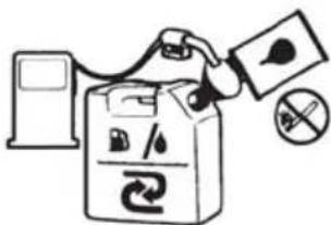
- Mix and pour fuel outdoors, where there are no sparks or flames.
- Do not smoke or place hot objects near fuel.
• Always shut off the engine before refuelling.
• Always stop the engine and let it cool for a few minutes before refuelling. - When refuelling, open the fuel cap slowly so that any excess pressure is released gently.
- Tighten the fuel cap carefully after refuelling.
- Always move the machine away from the refuelling area and source before starting.
• Always use a fuel container with an anti-spill valve. - If you have spilled fuel on it. Wipe off the spillage and allow remaining fuel to evaporate.
- Clean the area around the fuel cap. Contamination in the tank can cause operating problems.
- Ensure that the fuel is well mixed by shaking the container before filling the tank.
Precautions when refi lling chemicals
- Before fi lling the tank with chemicals, please make sure that the cock valve is completely at rest.
- After chemical refilling, firmly tighten the tank cap. If not fully tightened the cap may become loose during spraying, with the risk of physical exposure to the chemicals.
Precaution when starting the engine
- Please keep children, animals, etc. well away when starting the engine and spraying.
Precautions when spraying
- Since protective clothing generally offers poor ventilation and thus places stress on the body, there is a risk of contracting heatstroke or other illness when operating for long periods under high temperatures. Please avoid spraying on hot days, aiming instead for early
morning and late afternoon times when temperatures are relatively cool and winds are low.
- When starting work, please pay all due consideration to the spraying time, wind direction, etc., to ensure that no noise disturbance or chemical hazard is caused to nearby residents, passers-by, farm crops, and so on.
- While spraying please hold the grip firmly at all times and be careful not to point the nozzle in the direction of people or animals.
- While spraying please be careful of the wind direction and always stand on the upwind side, to avoid spraying yourself with chemicals.
- Should you begin to feel even slightly unwell while spraying, consult a doctor immediately. When doing so, inform the doctor of the name of the chemical you were using, the conditions of use, etc.
- If the sprayer is tilted the chemical may leak out through the air holes in the cap. When spraying always make sure you have a firm footing and maintain your balance.
- Do not touch the spark plug or plug cords while the engine is running, as you may get an electric shock.

- Do not touch the muffler, spark plug, or other metal parts with your bare hands while the engine is running or immediately after stopping the engine, as there is the risk of burns due to high temperatures.

Precautions after spraying
- Please seal unused chemicals and store them out of the reach of children.
- Do not simply discard empty chemical containers, but dispose of them safely by incinerating, burying, or another similar method. In addition, please take every care that the water used to clean spraying tools does not create any hazard.
- Fully inspect and maintain protective clothing, masks, gloves, and other protective gear in preparation for the next session.
- After completing the work and tidying away chemicals and spraying tools, you should immediately take a bath or wash your hands, feet, face, etc. thoroughly with soap, as well as washing your mouth out.
- You should change all clothes worn, including underwear, and wash them thoroughly. Clothes worn during spraying should not be worn again the following day.
- After spraying, please limit your alcohol intake and rest thoroughly by going to bed early. If you feel even slightly unwell, please see a doctor as soon as possible.
Other precautions
- When engaged in spraying work over a protracted period of time, please have your health checked regularly.
- Please carry out spraying in a planned fashion, keeping a daily record of the date and time of spraying, the chemicals used, the target pest, contents of the work, duration of the work, and other details.
- Please keep the following points in mind when selecting or using protective gear.
A. Protective clothing. Choose clothing that is cool to wear and offers good ventilation and waterproofing. In addition, wear items that enable you to carry out spraying work in total comfort and safety.
B. Spraying hood. Use a hood with a brim that is waterproof and covers your neck and shoulders.
C. Gloves. Use gloves that are difficult for chemicals to penetrate and do not slip even if you perspire while doing the work.
D. Rubber apron. When mixing chemicals, wear a long, thick, and wide apron that cannot be penetrated by chemical splashes.
E. Protective goggles, mask, etc. Select suitable protective goggles, mask, rubber boots, eye washer, and protective cream, etc., paying attention to standards and the recommendations of farm work safety promotion organizations.

natural_image
Four blue circular icons representing protective gear, boots, walking person, and gloves (no text or symbols)Maintenance precautions
- In order to maintain the functions of the product, regularly carry out the maintenance inspections listed in this Manual. When maintenance or parts replacement not indicated in this Manual are required, please consult your product supplier or nearest Husqvarna product dealer.
- Never keep the engine running while carrying out inspections or maintenance.
- Do not modify the sprayer or dismantle the engine. This could lead to breakdown and serious accidents during operation.
- Do not touch the muffler or spark plug with your bare hands immediately after stopping the engine. There is the risk of burns due to high temperature.

- For replacement parts, please use original Husqvarna parts or brands designated by Husqvarna.
Maintenance of labels
- Please keep warning labels clean and unmarked.
- If warning labels become soiled or peel off, please order from your supplier and replace with new ones.
- When affixing new labels please wipe off all dirt and moisture.
ASSEMBLY
To assemble the sprayer
- Connect the spray hose assembly and the pump outlet.
- Connect the spray hose assembly and spray rods.
- Install and adjust the straps assembly with the unit.
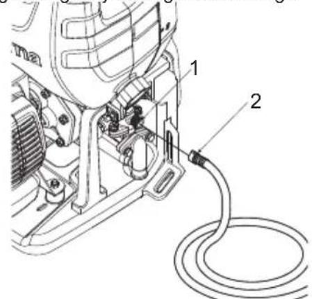
To connect the spray hose assembly and the pump outlet
- Attach the spray hose to the pump outlet (1) by tighening the wing nut (2). Tighten by hand only as overtightening may damage hose fittings.
To connect the spray hose assembly and spray rods
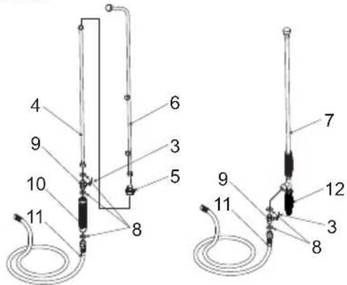
- For 3-nozzle spray rod: Screw the extension rod (4) onto the cock valve (3). Screw the ISO nozzle adapter (5) onto the extension rod (4). Screw the 3-nozzle spray rod (6) onto the ISO nozzle adapter (5). Ensure all connections are secured. Tighten by hand only.
- For single nozzle wand: Screw the single nozzle wand (7) onto the cock valve (3). Ensure the connection is secured. The single wand is equipped with the flow adjustment. Tighten by hand only.

NOTE
- If there is a leakage from the single nozzle wand (7) fittings, retighten the fittings with a spanner or multigrip.
- After the spray hose assembly is connected with the spray rod, inspect and ensure all connections in the spray hose assembly such as the seals (8), cock valve (9), handle (10), spray hose (11) and rear handle (12) are tightly secured (hand tighten only).

NOTE
- Use rear handle (12) to adjust spray volume and spray distance.
To install and adjust the straps assembly with the unit
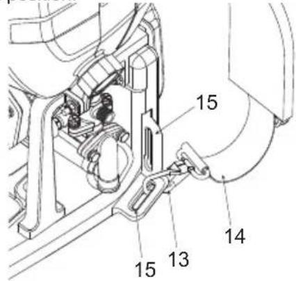
- Hook the harness clip (13) into the fastening eyelet (15).
- Slip the hardness strap (14) over your shoulder.
- Adjust the length of the strap for comfortable and balanced position.

NOTE
- Choose a different fastening eyelet (15), according to your height. Adjust to the most comfortable position.
Checklist before starting the sprayer

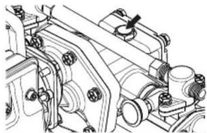
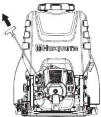
IMPORTANT
- Before starting the engine, remove the decal on the pump gearbox. The hole below the decal is an air pressure balance hole. If you do not remove the decal, it can cause abnormal pressure and gear oil leakages.
natural_image
Mechanical assembly diagram showing interconnected components with no visible text or symbolsReview the unit's assembly to ensure you have performed all of the following:
- Be sure to read Operator Safety and Operation before using the sprayer.
- Check for properly tightened hose connections and other connections including the spray hose assembly.
- Check to make sure there are no kinks, cuts, or damage to hoses.

WARNING
- Spray hose assembly and fi ttings are important for safety of the appliance. Use only hoses and fi ttings recommended by the manufacturer.

WARNING
- Gasoline is very fl ammable. Avoid smo king or bringing any fl ame or sparks near fuel. Make sure to stop the engine and allow it cool before refueling the unit. Select outdoor bare ground for fueling and move at least 3 m (10 ft) away from the fueling point before starting the engine.

natural_image
Illustration of a campfire with a no-smoking sign and smoke, symbolizing noise or fire (no text present)- The Husqvarna engines are lubricated by oil specially formulated for air-cooled 2-cycle gasoline engine use. If Husqvarna oil is not available, use an anti-oxidant added quality oil expressly labeled for air-cooled 2-cycle engine use (JASO FC GRADE OIL or ISO EGC GRADE).
- Do not use BIA or TCW (2-stroke water-cooling type) mixed oil.
• RECOMMENDED MIXING RATIO:
A. GASOLINE 50 : OIL 1 (when using Husqvarna genuine oil)
B. GASOLINE 25: OIL 1 (when using other oil)
• These engines are certified to operate on unleaded gasoline.
- Make sure to use gasoline with a minimum octane number of 89RON (USA/Canada: 87AL).
• Gasoline with up to 10% ethanol (gasohol) or up to 15% MTBE (methyl tertiary butyl ether) is acceptable.
- If you use a gasoline of a lower octane value than prescribed, there is a danger that the engine temperature may rise and an engine problem such as piston seizing may consequently occur.
- Clean, fresh and unleaded gasoline is recommended to reduce the contamination of the air for the sake of your health and the environment.
- Poor quality gasolines or oils may damage sealing rings, fuel lines or fuel tank of the engine.
To mix the fuel

WARNING
• Pay attention to agitation.
-
Measure out the quantities of gasoline and oil to be mixed.
-
Put some of the gasoline into a clean, approved fuel container.
-
Pour in all of the oil and agitate well.
-
Pour in the rest of gasoline and agitate again for at least one minute. As some oils may be difficult to agitate depending on oil ingredients, sufficient agitation is necessary for the engine to last long. Be careful that, if the agitation is insufficient, there is an increased danger of early piston seizing due to abnormally lean mixture.
-
Put a clear indication on the outside of the container to avoid mixing up with gasoline or other containers.
-
Indicate the contents on outside of container for easy identification.
To fuel the unit
-
Untwist and remove the fuel cap. Rest the cap on a dustless place.
-
Put fuel into the fuel tank to 80% of the full capacity.
-
Fasten the fuel cap securely and wipe up any fuel spillage around the unit.

WARNING
-
Select bare ground for fueling.
-
Move at least 3 meters (10 feet) away from the fueling point before starting the engine.
-
Stop the engine before refueling the unit. At that time, be sure to sufficiently agitate the mixed gasoline in the container.
FOR YOUR ENGINE LIFE, AVOID:
-
FUEL WITH NO OIL (RAW GASOLINE) It will cause severe damage to the internal engine parts very quickly.
-
GASOHOL - It can cause deterioration of rubber and/or plastic parts and disruption of engine lubrication.
-
OIL FOR 4-CYCLE ENGINE USE It can cause spark plug fouling, exhaust port blocking, or piston ring sticking.
-
Mixed fuels which have been left unused for a period of one month or more may clog the carbu retor and result in the engine failing to operate properly.
-
In the case of storing the product for a long period of time, clean the fuel tank after rendering it empty. Next, activate the engine and empty the carburetor of the composite fuel.
-
In the case of scrapping the used mixed oil container, scrap it only at an authorized repository site.

NOTE
- As for details of quality assurance, read the description in the section Limited Warranty carefully. Moreover, normal wear and change in product with no functional influence are not covered by the warranty. Also, be careful that, if the usage in the instruction manual is not observed as to the mixed gasoline, etc. described therein, it may not be covered by the warranty.
CHEMICAL FILLING
WARNING
- Chemical substances should be handled correctly, observing the precautions marked on the container. Some chemicals are extremely hazardous to humans and animals, and handling errors can cause serious poisoning or even fatal accidents.
- When not in use, chemical substance containers should be stored separately from other containers out of the reach of children.
IMPORTANT
- Do not fill the sprayer tank with undiluted fluid. This could cause the gasket and valves to lose their durability.
OPERATION
WARNING
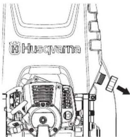
• Highly combustible. When refueling, switch the engine off and keep well away from naked flames.
• After filling the tank (2) with fuel, firmly tighten the cap (1).
To start the engine
IMPORTANT
- Before starting the engine, make sure that the cock valve (3) is completely returned. Starting with the cock valve still pulled out is dangerous, as chemical fluid may spray out of the nozzle as soon as the engine is started.
- Do not fill the sprayer tank with coarse particle fluid like bordeaux mixture or lime sulphur. This will shorten the service life of the machine.
Procedure for fi Iling
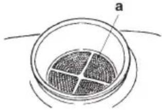
- Use a bucket or other suitable container and dilute the chemical to the requisite strength.
- Place the sprayer on an even and stable surface and remove the sprayer tank cap.
- Fill the tank by passing chemical through the strainer (a).
- When filling is complete, firmly tighten the cap.
natural_image
Diagram of a circular container with internal striped pattern and labeled point 'a' (no text or symbols beyond label)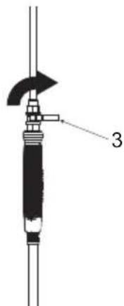
- To start the engine, place the sprayer on an even and stable surface or platform. If the sprayer is unstable, the reaction on starting etc. may cause it to fall.
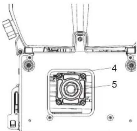
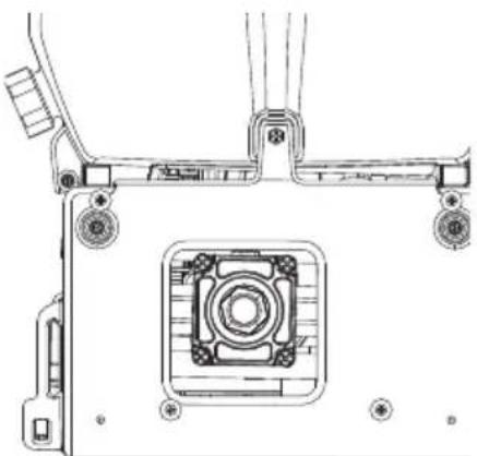
IMPORTANT
- Do not allow the chemical fluid or water in the tank to run out while the engine is running. If the engine runs empty it may cause breakage of the spray pump.
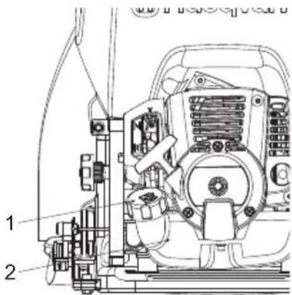
- Make sure that the gear oil is fi lled until the middle of the check-window (5). If it is not enough, loose the upper bolt (4) and fi ll the gear oil. (SAE40CC)
- Press the primer (6) at the bottom of the carburetor a few times with your finger until the fuel starts to flow through the transparent pipe.
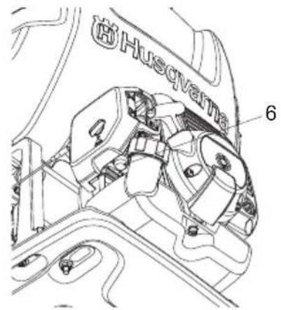

NOTE
- There is no need to operate the primer when restarting immediately after stopping the engine, provided there is fuel left in the fuel tank.
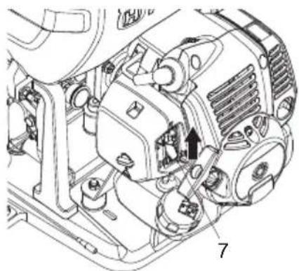
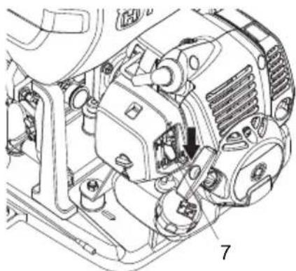
- Lift the choke lever (7) on the right of the air cleaner until it is in the "closed" position.
natural_image
Technical line drawing of a mechanical assembly with no visible text or symbols
NOTE
- When restarting immediately after stopping the engine, set the choke lever to "open".
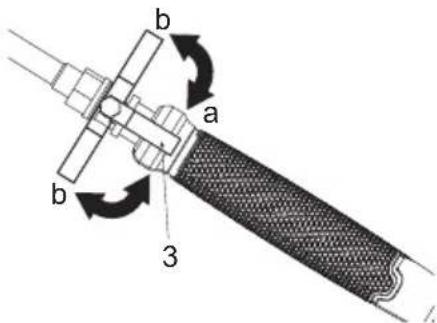
- Set the pressure regulating dial (8) to appropriate spray conditions. The pressure regulating dial is used to control the amount of pressure the pump will produce. When set, excess pressure is vented back into the tank supply to ensure a maximum output pressure at the wand. To set the pressure, follows these steps:
- Turn in clockwise direction to increase the pressure, or; Turn in anticlockwise direction to decrease the pressure.
- To lock the pressure regulating dial, tighten the pressure locking plate (9) in clockwise direction.
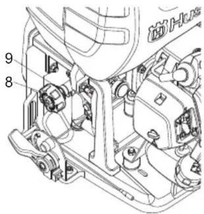

IMPORTANT
- Pressure has been set properly before delivery, do not change the pressure unless it is required.
- Place the sprayer in a stable location, and pull the starter knob with the right hand while holding the sprayer tank down with the left hand. The starter knob should first be pulled out lightly, then, when resistance is felt, pulled more swiftly and vigorously.
natural_image
Technical line drawing of a blue Huayama agricultural machine (no text or symbols)
IMPORTANT
- Do not pull the rope out completely or release the starter knob so that the rope returns, as this can cause starter malfunction.
- Once the engine has started, gradually open the choke lever (7), warm up at low speed for 1-2 minutes.
natural_image
Technical line drawing of an internal mechanical assembly (no text or symbols visible)IMPORTANT
- If the rope is pulled continuously with the choke closed, the spark plug may become fl ooded and the engine may fail to start. If so, you should fi rst remove the spark plug and dry the electrodes, then repeat the starting procedure.
To stop the engine
WARNING
- Stop the engine immediately in the event of an emergency.
- Lower the throttle lever (12) fully and cool the engine down for 1-2 minutes at low speed.
- Hold down stop switch (11) on the left side of the sprayer frame until the engine has come to a complete stop.
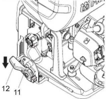
IMPORTANT
- Except for an emergency, avoid stopping the engine while pulling the throttle trigger.
To spray
WARNING
- Please use correctly, observing the precautions in this manual.
- Before lifting the sprayer onto your back, check that the sprayer tank cap and fuel tank cap are tightly closed.
- When spraying, do not point the nozzle at your face, or at other people, animals, etc.
- If the sprayer is tilted too much, chemical fluid or fuel may leak out through the air holes in the cap. When using, always try to maintain an upright posture.
IMPORTANT
- If the sprayer tank becomes empty while spraying, reduce the engine to low speed immediately. Empty running of the engine may cause the spray pump to break.
- Please avoid using multiple nozzles, jet nozzles, or other nozzles that give a large spray volume, as spraying effi ciency is sometimes impaired owing to insufficient pressure.
Spraying procedure
- Start the engine,
- Lift the sprayer onto your back.
- Adjust the carrying band to a suitable length for carrying.
- Increase the engine speed,
- Open the cock valve (3). Chemical fluid starts to spray out from the nozzle in the form of mist.
- When stopping work, close the cock valve (3) fully and reduce the engine speed.
a. open
b. close
Cleaning after completion of spraying
- Loosen the fluid drain cap, transfer the chemical fluid left inside the tank into a suitable container, and process appropriately with all due consideration to safety.
- Pour about 5 litres of clean water into the sprayer tank, spray through the nozzle for 2-3 minutes, and drain the water left inside the tank.
MAINTENANCE
WARNING
- Make sure that the engine has stopped and is cool before performing any service to the machine. Contact with hot muffler may result in a personal injury.
- Do not modify the sprayer or dismantle the engine.
- When replacing parts please use Husqvarna original parts or designated parts.
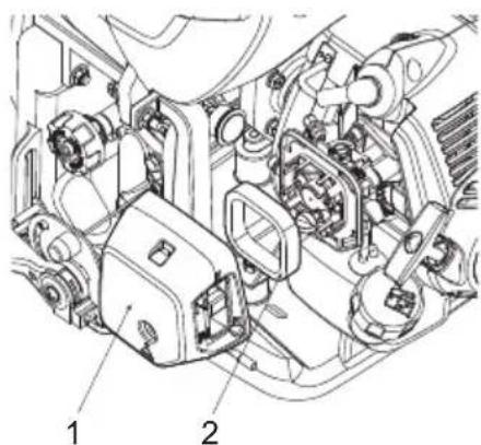
To check the air cleaner
- After every 25 hours of operation, please remove the air cleaner cover (1) and inspect the air cleaner (2). If it is too dirty, wash it carefully in warm water containing a neutral detergent, and return it to its original position after drying it thoroughly.
- If the air cleaner (2) is distorted or damaged, please replace it with a new one.
IMPORTANT
- If the air cleaner is blocked, the efficiency of the engine will be reduced. In addition, the engine interior will suffer abnormal wear if operated without the fi liter or if continually operated with a distorted or damaged fi liter fitted.
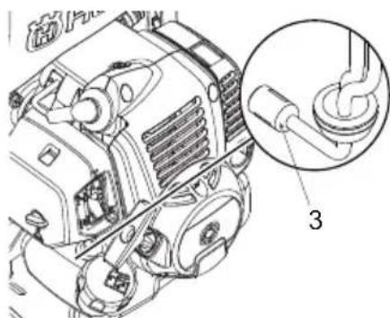
To check the fuel fi lter
- After every 25 hours of operation, empty the fuel tank, detach the fuel fi liter (3) from the tank, and remove all dirt. If the fi liter is too clogged, please replace it with a new one.
natural_image
Technical line drawing of an engine component with a magnified inset showing a pipe fitting (no text or symbols present)IMPORTANT
- If the fuel filter is clogged, the engine speed may be limited or speed fl ectuations may occur.
- If the engine is operated without a fuel filter, dirt will accumulate in the carburetor and cause it to malfunction.
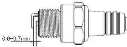
To check the spark plug
WARNING
- Do not touch the spark plug with your bare hands immediately after operation, as there is the risk of burns due to high temperature.

• After every 25 hours of operation, detach the spark plug and remove dirt from the electrodes with a wire brush or similar.
• The correct electrode gap is 0.6 to 0.7mm.
- When replacing plugs, please use designated items.
IMPORTANT
- If too much fuel is absorbed or poor quality oil is used, the spark plug electrodes become dirty, making the engine harder to start.
- Note that using any spark plug other than those designated may result in the engine failing to operate properly or in the engine becoming overheated and damaged.
- To install the spark plug, first turn the plug until it is fi nger tight, then tighten it a quarter turn more with a socket wrench.
TIGHTENING TORQUE: 14.7 to 21.6 N.m. (150 to 220 kgf-cm)
To adjust the engine speed
- Although the engine is adjusted on leaving the factory, after repeated use it may sometimes require readjustment or maintenance. Please consult your original supplier regarding inspections and maintenance other than those shown below.
To adjust idling speed
- If the engine stalls or the pump continues to move when in idling position with the throttle lever completely lowered, readjust the engine speed using the idle speed adjuster (4) on the left of the carburetor.
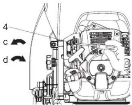
c. reduce speed d. increase speed
Turn the idling adjustment screw:
- Counter-clockwise to reduce engine speed
- Clockwise to increase engine speed

NOTE
- Warm up the engine before adjusting the idling speed.
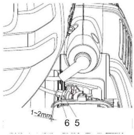
To adjust the throttle wire play
- Throttle wire play should be 1 to 2 mm.
- Take the throttle wire at the carburetor end in your fingers and give a light tug, after completely returning the throttle lever.
- Readjust the position of the wire retaining nut (6), if the play is too great or too small.
- Loosen the lock nut (5) and turn the wire retaining nut (6) clockwise (screw in) to increase the play and counter-clockwise (unscrew) to reduce it.
- Fasten the wire retaining nut by tightening the lock nut, after adjusting.
To check spray nozzle
A clogged spray nozzle can cause the spray pressure and flowrate to drop. All excessive pressure will go back to the sprayer tank.
To correct the problem, immediately clean the spray tip by following these instructions:
- Stop engine & remove the unit from the operators back.
- Disconnect the spray rod from the spray hose assembly.
- To remove the nozzle cap (7/9), turn in anticlockwise direction.
- Inspect and clean the spray tip (8/10) and metal strainer (11) for 3-nozzle spray rod from any foreign material clogging or restricting the spray nozzle. Replace if damaged.
- Reinstall the nozzle cap and the spray rod with the spray hose assembly tightly (hand tighten).
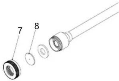
Single nozzle spray rod
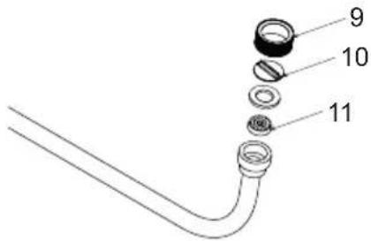
3-nozzle spray rod
To check the pump oil level
Oil level should be checked prior to each use.
- Make sure the sprayer is on a level surface.
- To get access to the back of the pump, you need to unbutton the top backpad only.
- Verify the oil is showing as 1/3-1/2's full (approx. 100ml) in the oil glass window.
- Replace and re-button the backpad into place before using.

NOTE
• DO NOT attempt any oil maintenance on this pump.
- The pump is pre-lubricated and sealed from the factory. If refi lling is required, see an Authorized Dealer or Service Centre.
natural_image
Technical line drawing of a mechanical assembly with mounting holes and a central circular component (no text or symbols)To check the muffler
WARNING
- Inspect periodically, the muffler for loose fasteners, any damage or corrosion. If any sign of exhaust leakage is found, stop using the machine and have it repaired immediately.
- Note that failing to do so may result in the engine catching on fi re.
Perform the procedures after every 100 hours of operation
- Remove the muffler, insert a screwdriver into the vent, and wipe away any carbon buildup. Wipe away any carbon buildup on the muffler exhaust vent and cylinder exhaust port at the same time.
- Tighten all screws, bolts, and fittings.
- Check to see if any oil or grease has worked its way in between the clutch lining and drum, and if it has, wipe it away using oil-free, lead-free gasoline.

natural_image
Line drawing of a hand using a tool to adjust or install a device (no text or symbols present)- Never touch the cylinder, muffler, or spark plug with your bare hands immediately after stopping the engine. The engine can become very hot when in operation, and doing so could result in severe burns.
- When checking the machine to make sure that it is okay before using it, check the area around the muffler and remove any wood chips or leaves which have attached themselves to the brushcutter. Failing to do so could cause the muffler to become overheated and that in turn could cause the engine to catch on fire. Always make sure that the muffler is clean and free of wood chips, leaves, and other waste before use.
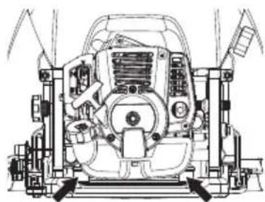
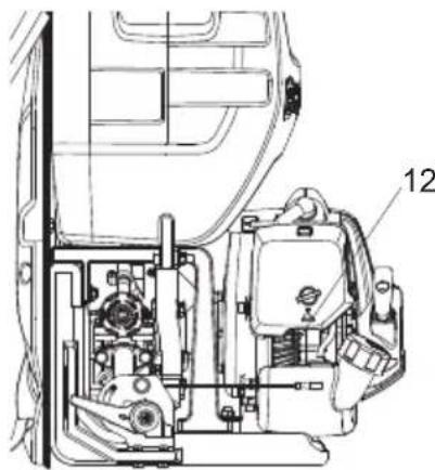
- Check the intake air cooling vent and the area around the cylinder cooling fi ns after every 25 hours of use for blockage. Note that it is necessary to remove the upper cover and the lower cover in order to be able to view the upper part of the cylinder.
IMPORTANT
- If waste gets stuck and causes blockage around the intake air cooling vent (12) or between the cylinder fins, it may cause the engine to overheat, and that in turn may cause mechanical failure on the part of the brushcutter.
natural_image
Technical line drawing of a mechanical assembly with labeled component (12), no readable text or symbols present.To replace the gear oil
- After first 25 hours of use, replace the gear oil. After that, replace it after every 100 hours of use (SAE90, 100cc).
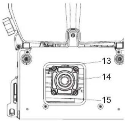
(13) Upper bolt
(14) Check-window
(15) Drain bolt
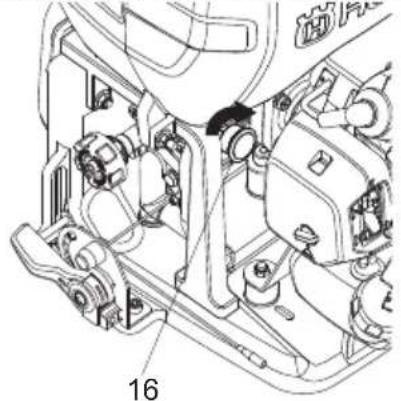
To check the grease cups
- Open the upper cap (16) of the grease cup and check the grease amount. Fill it up if it is decreasing.
natural_image
Technical line drawing of a mechanical assembly with numbered component (16), no readable text or symbols present.| Maintenance procedure Daily Weekly | Monthly Note | |||
| Overall | ||||
| Inspect the whole unit for damage, leak or spillage | √ | |||
| Inspect all accessible fasteners | √ | Tighten or replace if necessary | ||
| Inspect all screws/nuts/bolts | √ | Tighten or replace if necessary. Adjusting screws are not included. | ||
| Check the hoses and fittings | √ | |||
| Clean for any debris | √ | |||
| Engine | ||||
| Inspect and clean the fuel tank | √ | |||
| Inspect and clean the fuel filter | √ | |||
| Inspect and clean the air cleaner | √ | |||
| Check the operation of the throttle lever and stop switch. | √ | |||
| Empty the fuel tank | √ | |||
| Apply grease to the plunger | √ | |||
| Clean or re-adjust the spark plug gap | √ | Make sure the gap is 0.6 to 0.7m (.025in). Replace if necessary | ||
| Maintenance procedure Daily Weekly Monthly Note | ||||
| Inspect the muffler for damage. | √ | Replace if necessary | ||
| Clean the muffler and the cylinder exhaust port | √ | |||
| Clean the cylinder fins and intake air cooling fan | √ | |||
| Sprayer tank and spray nozzels | ||||
| Check/clean the sprayer tank strainer √ | Clean if clogged.Replace if damaged or torn. | |||
| Empty and clean the sprayer tank √ | ||||
| Check the spray nozzles √ | ||||
| Pump | ||||
| Check the level of the pump oil √ | ||||
| Replace the gear oil √ | ||||
| Check the grease cups | √ | Refill if necessary | ||
DISPOSAL AND STORAGE
Disposal
When disposing your machine, fuel or oil for the machine, be sure to allow your local regulations.
Storage
WARNING
- When draining fuel, please be careful not to spill it. If fuel is spilt, wipe off thoroughly. In addition, please be sure to close the storage container cap tightly.
IMPORTANT
- If fuel is left in the engine for protracted periods, the inside of the carburetor may become clogged and cause engine malfunction (faulty starting and insufficient output).
- During storage, slightly loosen the cap of the chemical fluid tank. If screwed too tightly, the gasket may become distorted.
On completion of all work procedures, when not planning to use again for a protracted period please carry out the following pre-storage care, to prevent trouble caused by time-lapse changes.
- Clean the chemical fluid tank and nozzle (see page 13).
-
Remove dirt from the sprayer, inspect it for any damage or looseness, and, if any abnormality is found, correct it thoroughly in preparation for the next time you use the unit.
-
Drain the fuel tank.
- Start the engine, and leave it in idling condition until all the fuel inside the carburetor is spent and the engine comes to a natural stop.
- Remove the spark plug and put a few drops (1 to 2 cc) of 2-cycle oil inside the engine. After pulling the starter rope 2 or 3 times, return the spark plug to their original position and stop in compressed position.
- After oiling the throttle lever and other metal parts with anti-corrosive oil, cover the sprayer and store indoors in a low-humidity location.
IMPORTANT
- Keep the sprayer upright when you do not use it and store it. If the sprayer is not upright, gear oil leakages can occur from the pressure balance hole of pump gearbox.
natural_image
Technical line drawing of a mechanical pump assembly with hoses and control components (no text or symbols)TROUBLESHOOTING
| Problem Possible causes Remedy | ||
| Engine will not start | Electrode spark plug is wet or fouled | Clean or replace the spark plug |
| Cracked spark plug insulator Replace the spark plug | ||
| Incorrect spark plug gap Adjust gap | 0.6 - 0.7mm | |
| Engine fl ooded | Crank engine with choke open and full throttle to clear excess fuel | |
| Incorrect or stale fuel Drain and replace with correct fuel/oil mixture | ||
| No fuel in tank Refuel with correct fuel/oil mixture | ||
| Insuffi cient power | Clogged air cleaner Clean and lubricate air cleaner | |
| Fuel line/passage clogged | Contact Service Centre or see Authorized Dealer | |
| Carbon build up in muffler | Contact Service Centre or see Authorized Dealer | |
| Use incorrect or stale fuel Drain and replace with correct fuel/oil mixture | ||
| Piston seizure | Contact Service Centre or see Authorized Dealer | |
| Machine is overworked Operate properly - do not overload | ||
| Engine stops during operation | Switch is bumped Restart the engine | |
| Shorting of spark plug Clean spark plug or replace | ||
| Piston scored | Contact Service Centre or see Authorized Dealer | |
| Fuel tank is empty Refuel with correct fuel/oil mixture | ||
| Carburettor or fuel tank clogged | Contact Service Centre or see Authorized Dealer | |
| Engine is diffi cult to stop | Stop wire disconnected from the switch | Attach stop wire to switch |
| Overheated engin | Contact service centre or see Authorized Dealer | |
| Unit main body | Loose engine and/or pump mounts | Retignten engine and/or pump mount screws |
| Tank leak | Contact service centre or see Authorized Dealer | |
| Leak at the tube connections | Retignten the hose clip or replace if damaged | |
| Pump is no spraying | No chemical diluted liquid in the sprayer tank | Fill the sprayer tank |
| Valves inside the pump clogged | Contact Service Centre or see Authorized Dealer | |
| Cock valve blocked Clean the cock | valve or replace | |
| Incorrect pressure setting-too low Adjust the pressure regulating dial | ||
| Pump is worn out or damaged | Contact Service Centre or see Authorized Dealer | |
| Spray rod nozzle clogged Clean the nozzle | ||
| Insuffi cient spray pressure | Pump speed or pressure setting too low | Adjust the pump speed and pressure regulating dial |
| Spray rod nozzle clogged Clean the | nozzle | |
| Pump seals and/or vee-packing seals worn or damaged | Contact Service Centre or see Authorized Dealer | |
| One way valve(s) inside the pump clogged | Contact Service Centre or see Authorized Dealer | |
| Clutch slipping Replace the clutch | ||
| Lack of lubrication Apply grease onto the plunger | ||
| Burst spray hose | Contact Service Centre or see Authorized Dealer | |
| Spray rod nozzle worn or damaged | Contact Service Centre or see Authorized Dealer | |
If running difficulties continue, contact your closest Authorized Dealer or Service Centre.
TECHNICAL DATA
| Product model 321S15 321S25 | |||
| Pump | Type Plunger type | ||
| Working Pressure (MPa) * 1.5-3.0 | |||
| Max. Pressure (MPa) * 3.5 | |||
| Max. Working Flowrate (LPM) * 7 | |||
| Engine | Type Single-cylinder air-cooled 2-stroke gasoline engine | ||
| Engine Displacement (cc) 25.4 | |||
| Max. Power/Speed (kW/rpm) * | 0.75/7000 | ||
| Engine Operating Speed (rpm)** | 7000 | ||
| Idling speed (rpm) 3000 | |||
| Fuel Type Gasoline/Oil Mixture | |||
| Oil | 2-stroke | ||
| Admixture ratio | 25:1,50:1(Only Husqvarna genuine oil) | ||
| Starter system Easy starter | |||
| Spark plug | LD L7T, CDK L8RTC | ||
| External dimensions of main unit (mm)L*W*H: | 395*370*556 400*370*632 | ||
| Capacity of sprayer tank (L) 15 25 | |||
| Gross Mass: Empty (kg) | 9.2 | 10 | |
| Capacity of fuel tank (L) | 0.6 | 0.6 | |

NOTE
* Rated in accordance with manufacturers test standard
** The maximum engine operating speed is deliberately set to 7000rpm by the manufacturer to optimise the engine and pump performance and life
Due to product improvements, these specifications are subject to change without notice.
Descrição das peças
natural_image
Illustration of a child holding a large bag with a crossed-out pie chart and no visible text or symbols
natural_image
Cartoon illustration of a worker in a hard hat pointing toward rain, with raindrops falling (no text or symbols)natural_image
Cartoon illustration of a distressed person sitting on stomach with steam lines (no text or symbols)


NOTA
natural_image
Technical line drawing of an engine assembly with no visible text or symbolsnatural_image
Illustration of a no-smoking cigarette with smoke and flames (no text or symbols)Para arrancar o motor
IMPORTANTE
natural_image
Diagram of a circular container with internal compartments, labeled 'a' (no text or symbols beyond label)
natural_image
Technical line drawing of a mechanical assembly with gears and housing (no text or symbols)NOTA
natural_image
Technical line drawing of a blue water spray gun with attached pump and control panel (no text or symbols)IMPORTANTE
natural_image
Technical line drawing of a mechanical assembly with no visible text or symbolsIMPORTANTE
IMPORTANTE
IMPORTANTE
IMPORTANTE
IMPORTANTE
natural_image
Technical line drawing of a mechanical assembly with mounting holes and a central circular component (no text or symbols)natural_image
Line drawing of a hand using a tool to adjust or install a device (no text or symbols present)natural_image
Technical line drawing of a mechanical assembly with labeled component (12), no readable text or symbols present.Para substituir o óleo de engrenagens
natural_image
Technical line drawing of a mechanical assembly with numbered component (16), no readable text or symbols present.natural_image
Technical line drawing of a mechanical pressure pump assembly (no text or symbols)Note the following before starting: 3
INTRODUCTION
Dear Customer, 4
WHAT IS WHAT? 5
SAFETY
For safe operation 6
ASSEMBLY
To assemble the sprayer 9
To connect the spray hose assembly and the pump outlet 9
To connect the spray hose assembly and spray rods 9
To install and adjust the straps assembly with the unit 9
Checklist before starting the sprayer 9
FUEL
To mix the fuel 10
To fuel the unit ....10
CHEMICAL FILLING
Procedure for fi lling ....11
OPERATION
To start the engine ....11
To stop the engine ....13
To spray 13
Spraying procedure 13
Cleaning after completion of spraying ..... 13
MAINTENANCE
To check the air cleaner 14
To check the fuel fi iter 14
To check the spark plug 14
To adjust the engine speed 14
To check spray nozzle ....15
To check the pump oil level 15
To check the muffler 16
To check the air cooling fan ....16
To replace the gear oil 16
To check the grease cups 17
DISPOSAL AND STORAGE
Disposal....18
Storage....18
TROUBLESHOOTING
TECHNICAL DATA
Componentes
natural_image
Illustration of a child holding a baby with a no-smoking symbol in the background (no text or symbols present)
natural_image
Illustration of a worker in a hard hat pointing forward with raindrops falling (no text or symbols)natural_image
Cartoon illustration of a boy sitting with steam lines around, showing distressed expression (no text or symbols)natural_image
Technical line drawing of a mechanical device with internal components and an illustration of a person holding a tool (no text or symbols present)ADVERTENCIA


NOTA
natural_image
Mechanical assembly diagram showing engine components and a valve (no text or labels)natural_image
Illustration of a no-smoking cigarette emitting smoke, with flames and smoke nearby (no text or symbols)natural_image
Diagram of a circular container with internal mesh structure, labeled 'a' (no text or symbols beyond label)ADVERTENCIA
Arranque del motor
IMPORTANTE
natural_image
Technical line drawing of a mechanical assembly with no visible text or symbols
NOTA
natural_image
Technical line drawing of a mechanical device with no visible text or symbols
IMPORTANTE
natural_image
Technical line drawing of an engine compartment with no visible text or symbols
IMPORTANTE
IMPORTANTE
natural_image
Technical line drawing of a mechanical assembly with numbered components (no text or symbols)IMPORTANTE
IMPORTANTE
IMPORTANTE
natural_image
Technical line drawing of a mechanical assembly with mounting holes and a central circular component (no text or symbols)natural_image
Line drawing of a hand using a tool to adjust or install a device (no text or symbols present)natural_image
Technical line drawing of a mechanical assembly with labeled component (12), no readable text or symbols present.natural_image
Mechanical assembly diagram showing internal components and a numbered label (16), no readable text or symbols present.natural_image
Line drawing of a pressure pump assembly with hoses and control valves (no text or symbols)Note the following before starting: 3
INTRODUCTION
Dear Customer, 4
WHAT IS WHAT? 5
SAFETY
For safe operation 6
ASSEMBLY
To assemble the sprayer 9
To connect the spray hose assembly and the pump outlet 9
To connect the spray hose assembly and spray rods 9
To install and adjust the straps assembly with the unit 9
Checklist before starting the sprayer 9
FUEL
To mix the fuel 10
To fuel the unit 10
CHEMICAL FILLING
Procedure for fi lling 11
OPERATION
To start the engine 11
To stop the engine 13
To spray 13
Spraying procedure 13
Cleaning after completion of spraying ..... 13
MAINTENANCE
To check the air cleaner 14
To check the fuel fi Iter 14
To check the spark plug 14
To adjust the engine speed 14
To check spray nozzle 15
To check the pump oil level 15
To check the muffler 16
To check the air cooling fan ....16
To replace the gear oil 16
To check the grease cups 17
DISPOSAL AND STORAGE
Disposal....18
Storage....18
TROUBLESHOOTING
TECHNICAL DATA
natural_image
Illustration of a child holding a large bowl with a prohibition symbol in the background (no text or symbols present)
natural_image
Illustration of a worker in a hard hat pointing toward raindrops (no text or symbols)natural_image
Cartoon illustration of a person sitting on their back with steam rising (no text or symbols)natural_image
Technical line drawing of a mechanical assembly with no visible text or symbols
▲ AVERTISSEMENT

natural_image
Technical line drawing of an internal combustion engine assembly (no text or labels)natural_image
Illustration of a no-smoking cigarette inside a campfire, with flames and smoke (no text or symbols)• RAPPORT DE MÉLANGE RECOMMANDÉ :
APPOINT EN PRODUITS CHIMIQUES
▲ AVERTISSEMENT
natural_image
Diagram of a circular container with internal compartments, labeled 'a' (no text or symbols beyond label)FONCTIONNEMENT
AVERTISSEMENT
natural_image
Technical line drawing of a mechanical assembly with no visible text or symbols
REMARQUE
natural_image
Technical line drawing of a mechanical device with no visible text or symbols
IMPORTANT
natural_image
Technical line drawing of an internal combustion engine component (no text or labels)
IMPORTANT
IMPORTANT
natural_image
Technical line drawing of a mechanical assembly with numbered components (no text or symbols)IMPORTANT
natural_image
Technical diagram of an engine component with a magnified inset showing a pipe fitting (no text or symbols present)IMPORTANT
IMPORTANT
natural_image
Technical line drawing of a mechanical assembly with mounting holes and a central component (no text or symbols)natural_image
Line drawing of a hand using a tool to adjust or install a device (no text or symbols present)natural_image
Technical line drawing of a mechanical assembly with labeled component '12' (no text or symbols beyond label)natural_image
Technical line drawing of a mechanical assembly with numbered component (16), no readable text or symbols present.natural_image
Line drawing of a pressure pump assembly with hoses and control valves (no text or symbols)Original instructions


- Operator's manual Manual do utilizador Manual de usuario Manuel d'utilisation
- Symbols
- Contents
- KEY TO SYMBOLS
- INTRODUCTION
- SAFETY
- ASSEMBLY
- FUEL
- CHEMICAL FILLING
- OPERATION
- MAINTENANCE
- DISPOSAL AND STORAGE
- TROUBLESHOOTING
- TECHNICAL DATA
- Note the following before starting:
- PRECAUTIONS
- WARNINGS IN THE MANUAL
- WARNING
- IMPORTANT
- NOTE
- Dear Customer,
- WHAT IS WHAT?
- For safe operation
- Before using the product
- Check and follow the local regulations as to sound level and hours of operations for the product.
- Precautions before spraying
- Precautions when transporting chemicals
- Precautions when transporting the sprayer
- Precautions concerning fuel
- Taking the following precautions, will lessen the risk of fi re:
- Precautions when refi lling chemicals
- Precaution when starting the engine
- Precautions when spraying
- Precautions after spraying
- Other precautions
- Maintenance precautions
- Maintenance of labels
- To assemble the sprayer
- To connect the spray hose assembly and the pump outlet
- To connect the spray hose assembly and spray rods
- To install and adjust the straps assembly with the unit
- Checklist before starting the sprayer
- To mix the fuel
- To fuel the unit
- FOR YOUR ENGINE LIFE, AVOID:
- To start the engine
- Procedure for fi Iling
- To stop the engine
- To spray
- Spraying procedure
- Cleaning after completion of spraying
- To check the air cleaner
- To check the fuel fi lter
- To check the spark plug
- To adjust the engine speed
- To adjust idling speed
- Turn the idling adjustment screw:
- To adjust the throttle wire play
- To check spray nozzle
- To check the pump oil level
- Perform the procedures after every 100 hours of operation
- To replace the gear oil
- To check the grease cups
- Disposal
- Storage
- Descrição das peças
- NOTA
- Para arrancar o motor
- IMPORTANTE
- Para substituir o óleo de engrenagens
- Componentes
- ADVERTENCIA
- Arranque del motor
- ▲ AVERTISSEMENT
- APPOINT EN PRODUITS CHIMIQUES
- FONCTIONNEMENT
- AVERTISSEMENT
- REMARQUE
Brand : HUSQVARNA
Model : 321S15
Category : Electric mower