
Sofia 60 - Range hood Klarstein - Free user manual and instructions
Find the device manual for free Sofia 60 Klarstein in PDF.

| Product Type | Decorative Hood |
| Brand | Klarstein |
| Model | Sofia 60 |
| Width | 600 mm |
| Depth | 500 mm (approx.) |
| Height | Adjustable, min. 717 mm above the cooking surface |
| Weight | Approx. 10 kg |
| Power Supply | 220-240 V ~ 50 Hz |
| Motor Power | 45.7 W (at best point) |
| Number of Speeds | 3 speeds |
| Max Airflow | 306.1 m³/h |
| Noise Level | 54 dB (min) / 65 dB (max) |
| Lighting | LED, 1.5 W max |
| Grease Filter | Metallic, dishwasher-safe |
| Activated Carbon Filter | Optional, replace every 4 months |
| Energy Efficiency Class | B |
| Annual Energy Consumption | 25.9 kWh |
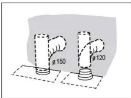
| Extraction Duct Diameter | 150 mm or 120 mm (with reducer) |
| Mode of Operation | Extraction or recirculation (with carbon filter) |
| Controls | Touch controls, with digital display |
| Warranty | 2 years (depending on retailer) |
Frequently Asked Questions - Sofia 60 Klarstein
User questions about Sofia 60 Klarstein
0 question about this device. Answer the ones you know or ask your own.
Ask a new question about this device
Download the instructions for your Range hood in PDF format for free! Find your manual Sofia 60 - Klarstein and take your electronic device back in hand. On this page are published all the documents necessary for the use of your device. Sofia 60 by Klarstein.
USER MANUAL Sofia 60 Klarstein
INHALTSVERZEICHNIS
INSTALLATIONSZUBEHÖR

natural_image
Technical line drawing of a mechanical device with mounting bracket and internal components (no text or symbols)natural_image
Illustration of a hand inserting a device into a screen, showing a curved arrow (no text or symbols)Aktivkohlefilter (Umluftversion)
natural_image
Pure mechanical diagram showing a rectangular frame with internal components and directional arrows, no text or symbols present.Entfernen:
natural_image
Line drawing of a car seatbelt buckle securing a vehicle (no text or symbols)1

natural_image
Pure technical line drawing of a mechanical component or bracket (no text or symbols)
natural_image
Technical line drawing of a mechanical component with a curved top and rectangular base (no text or symbols)2
Ersatzlicht
natural_image
Symbol of a trash bin crossed with a diagonal line, no text or numbers presentBerlin Brands Group UK Limited
PO Box 42
272 Kensington High Street
London, W8 6ND
United Kingdom
Dear Customer,
Congratulations on purchasing this device. Please read the following instructions carefully and follow them to prevent possible damages. We assume no liability for damage caused by disregard of the instructions and improper use. Scan the QR code to get access to the latest user manual and more product information.

CONTENTS
Safety Instructions 26
Product Overview 28
Installation Components 29
Dimensions 30
Installation 32
Chimney Assembly 35
Key Functions 36
Care and Cleaning 37
Troubleshooting 39
Notes on Environmental Protection 41
Product Data Sheet 42
Disposal Considerations 44
Manufacturer & Importer (UK) 44
TECHNICAL DATA
| Item number | 10034258, 10034259, 10034260, 10034261 |
| Power supply 220-240 V ~ 50 Hz |
SAFETY INSTRUCTIONS
- Thank you for purchasing this cooker hood. Please read the instruction manual carefully before you use the cooker hood, and keep it in a safe place.
- The installation work must be carried out by a qualified electrician or competent person. Before you use the cooker hood, make sure that the voltage (V) and the frequency (Hz) indicated on the cooker hood are exactly the same as the voltage and the frequency in your home.
- The manufacturer and the agent will not bear any responsibility for the damage caused by inappropriate installation and usage.
• Children under the age of 8 must not use the cooker hood. - The appliance is not intended for commercial use, but only for household and similar environments.
- The cooker hood and its filter mesh should be cleaned regularly in order to keep it in good working order.
• Before cleaning, switch the power off at the main supply. - Clean the cooker hood according to the instruction manual and keep the cooker hood from the danger of burning.
• Prohibit putting the cooker hood by fire. - If the appliance does not function normally, contact the manufacturer or a specialist company.
- This device may be only used by children 8 years old or older and persons with limited physical, sensory and mental capabilities and / or lack of experience and knowledge, provided that they have been instructed in use of the device by a responsible person who understands the associated risks.
- If the supply cord is damaged, it must be replaced by the manufacturer, its service agent or similarly qualified persons in order to avoid a hazard.
- If the range hood is used at the same time as appliances burning gas or other fuels, the room must be adequately ventilated.
- Do not flambé under the range hood. Accessible parts may become hot when used with cooking appliances.
Important hints on installation
- The air must not be discharged into a flue that is used for exhausting fumes from appliances burning gas or other fuels (not applicable to appliances that only discharge the air back into the room).
• Regulations concerning the discharge of air have to be fulfilled.
Important notes about the extraction mode

WARNING
Risk of poisoning from exhaust gases sucked back. Never operate the device in extraction mode simultaneously with an open flue appliance when there is not adequate airflow guaranteed.
Open fl ue combustion equipment (for example, gas, oil, wood or coal-fi red heaters, tankless water heaters, water heaters) pulls combustion air from the room and runs it through an exhaust pipe or chimney to the outside. In the extraction mode, indoor air is removed from the kitchen and the adjacent rooms - without sufficient air intake this creates a vacuum. Toxic gases from the chimney or extraction fl ue can thereby be sucked back into the living spaces.
- Always ensure that a sufficient supply of fresh air is guaranteed and that the air can circulate.
- An air supply / extractor box alone does not ensure compliance with the limit value.
Safe operation is only possible when the negative pressure in the room where the appliance is located does not exceed 4 Pa (0.04 mbar). This can be achieved when the air required for combustion can flow through openings that are not closable, for example in doors, windows, in conjunction with an air supply / extractor box or through other technical measures. In any case, consult a qualified chimney sweep who can assess the entire ventilation of your house and propose appropriate measures for adequate ventilation.
If the hood is used exclusively in the recirculation mode, unrestricted operation is possible.
Important note on disassembly of the device
- Disassembly is similar to installation/assembly in reverse order.
• Take a second person to help you during disassembly to avoid injuries.
PRODUCT OVERVIEW
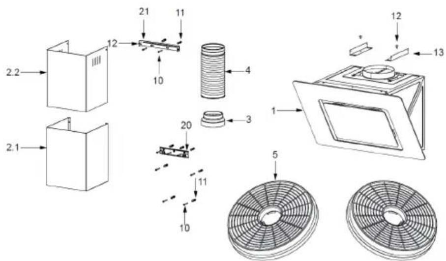
| Ref. Qty. | Product Components |
| 1 1 Hood | Body, complete with:Controls, Light, Blower, Filter. |
| 2.1 1 Lower Decorative Chimney (optional) | |
| 2.2 1 Upper Decorative Chimney (optional) | |
| 3 1 Flange (optional) | |
| 4 1 Exhaust Pipe | |
| 5 2 The Activated Charcoal filter (optional) | |
Note: The optional accessory is not included in the delivery.
INSTALLATION COMPONENTS
 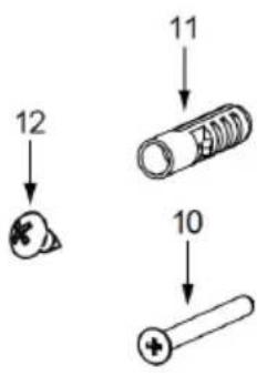  | ||
| Ref. Qty. | Component | |
| 107 Screws 5 x 50 | ||
| 117 Wall Plugs | ||
| 126 Screws 4,2 x 9,5 | ||
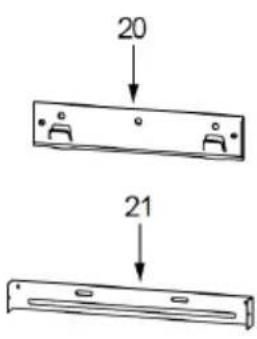
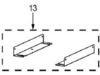
| 132 Mounting Bracket | ||
| 201 Hood fixing bracket (optional) | ||
| 211 Chimney fixing bracket (optional) | ||
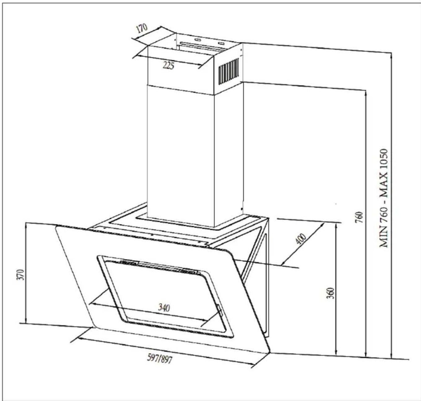
DIMENSIONS
Note: The specified values are [mm].
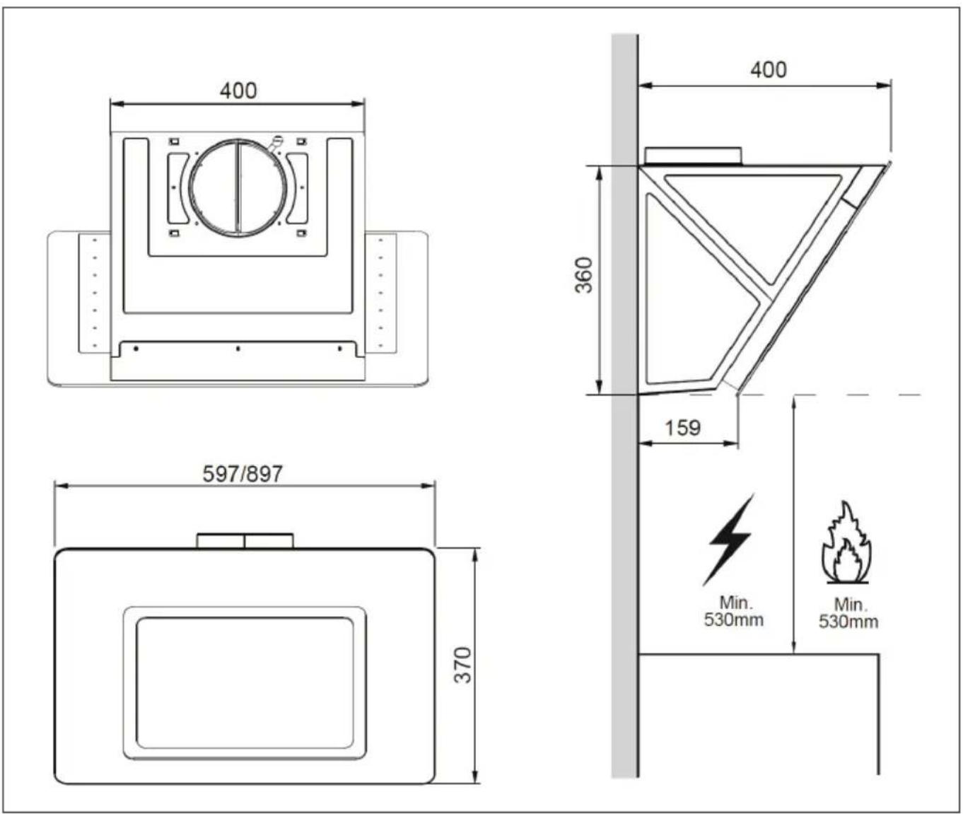
Note: The specified values are [mm].
INSTALLATION
Note: The specified values are [mm].
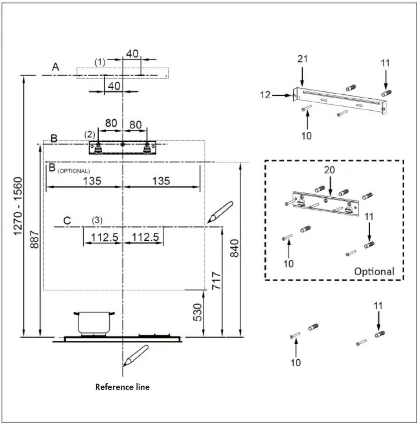
Wall Drilling and Bracket Fixing
As a first step, proceed with the following drawings:
- A vertical line up to the ceiling or up to the upper limit, at the center of the area in which the hood is to be fitted.
(A) A horizontal line A at 1270–1560 mm above the cooker top.
(B) A horizontal line B at a minimum 887 mm (840 mm optional) above the cooker top.
(C) A horizontal line C at a minimum 717 mm above the cooker top.
Mark Points
Note: The specified values are [mm].
(1) Mark a point (1) on the horizontal line A, 40 mm to the right of the vertical reference line. Repeat this step on the left side of the reference line and make sure that the two points are at the same height.
(2) Mark a point (2) on the horizontal line B, 80 mm (135 mm optional) to the right of the vertical reference line. Repeat this operation on the other side and on the vertical reference line, checking that the three marks are leveled.
(3) Mark a point (3) on the horizontal line C, 112.5 mm to the right of the vertical reference line. Repeat this operation on the other side, checking that the two marks are on the same horizontal line.
Fix the Brackets (Optional)
- Drill at the marked points (1) (2) (3), using a 10 mm drill bit.
- Insert the Wall Plugs into the holes (1) (2) (3).
- Fix the hood fixing bracket with 3 screws (5 x 50) supplied with the hood.
- Fix a Chimney fixing bracket with 2 screws (5 x 50) supplied with the hood.
Hook the Hood Body
- Open the panel.
- Remove the Metal grease filter using the handles provided.
- Hook the hood body to the bracket (20).
• Level the hood body itself.
• From the inside of the hood body, fix the screws (10) to Wall Plugs at the points (3).
• Fit the filter into the hood.
- Close the panel.
Connections to Ducted Version Air Exhaust System
When installing the ducted version, connect the hood to the chimney using either a flexible or rigid pipe 150 mm or 120 mm, the choice of which is left to the installer.
- If to install a 120 mm air exhaust connection, insert the reducer flange on the hood body outlet.
• Fix the pipe in position using sufficient pipe clamps (not supplied). - Remove possible charcoal filters.
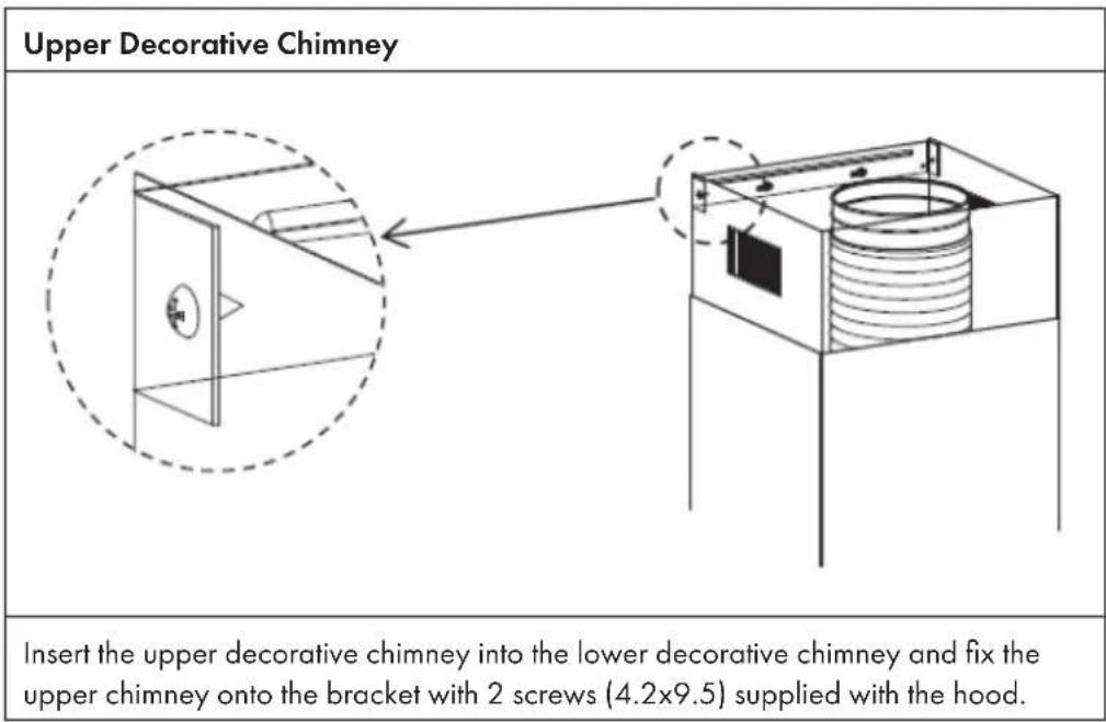
CHIMNEY ASSEMBLY
The chimney can only be installed with exhausting hood.
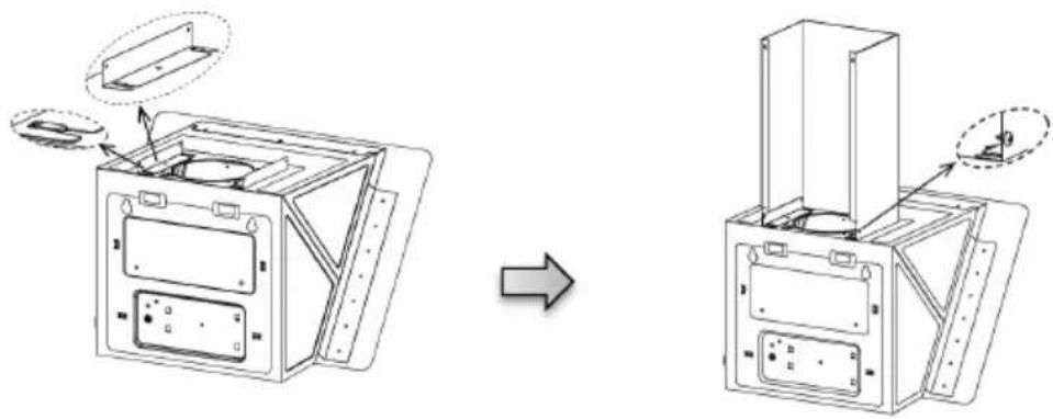
Lower Decorative Chimney
Fix the Lower Decorative Chimney to Chimney fixing bracket with 2 screws (4.2*9.5) supplied with the hood.
natural_image
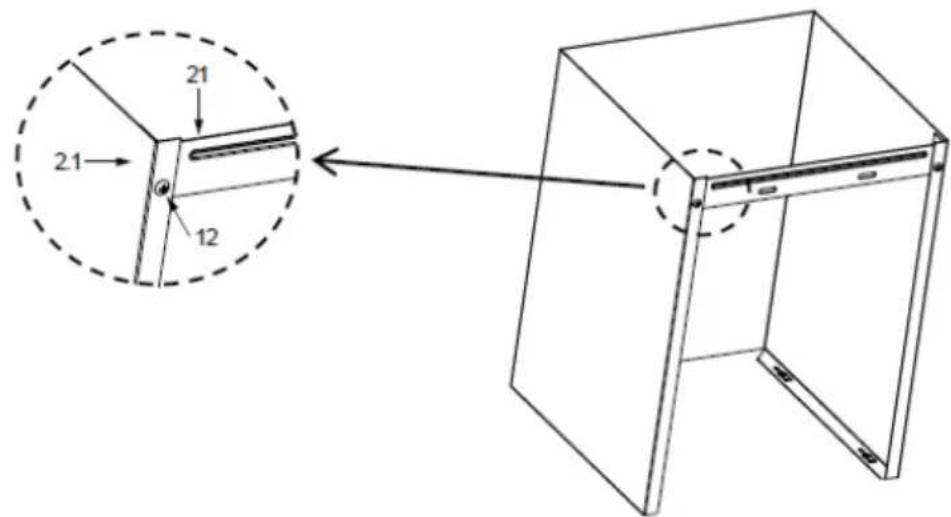
Technical line drawing of a device casing with internal components, showing assembly before and after transformation (no text or symbols)Hook the brackets (13) onto the hood body, and fix them with 2 screws 12 (4.2 x 9.5), making sure that they are well seated. Slightly widen the two sides of the lower chimney and hook then between the brackets (13), fix the lower chimney onto the brackets with 2 screws (4.2 x 9.5) supplied with the hood.
KEY FUNCTIONS
 — —    | |
| Switch the light on/off (when the button is lit). | |
| Reduce motor speed (when switched on). | |
| Indicates the motor speed (when the motor is switched on). | |
| Displays [0] when the unit is shutting down or in standby mode. | |
| Increase motor speed (when on). | |
| Turns the motor on (in the off state). | |
| Turns the motor off after 3 minutes (when on). | |
| Turns the motor off (when the button flashes). | |
CARE AND CLEANING
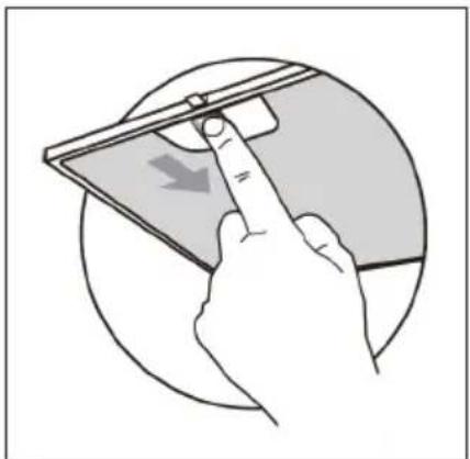
Grease Filters
- The filters must be cleaned every 2 months of operation, or more frequently for particularly heavy usage, and can be washed in a dishwasher.
- Remove the filters one by one pushing them towards the back side of the hood unit and simultaneously pulling downwards.
- Any kind of bending of the filters has to be avoided when washing them. Before fitting them again into the hood make sure that they are completely dry. (The color of the filter surface may change throughout the time but this has no influence to the filter efficiency).
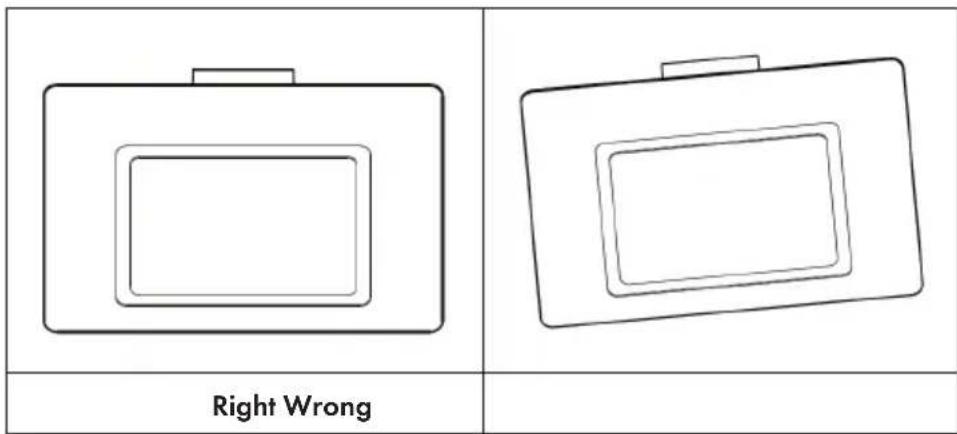
- When fitting the filters into the hood pay attention that they are mounted in correct position the handle facing outwards.
natural_image
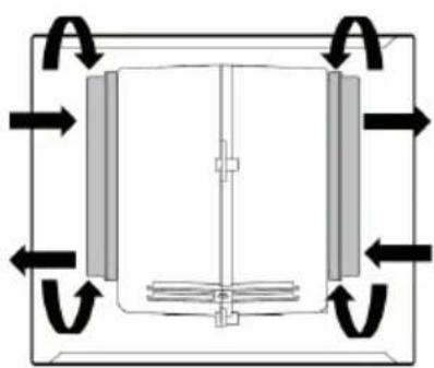
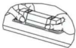
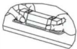
Illustration of a hand inserting a device into a screen, showing a curved arrow (no text or symbols)Activated carbon filter (circulating air version)
These filters cannot be washed off and reused. Depending on the frequency of use, activated carbon filters must be replaced at least every 4 months.
Replacing the activated carbon filters:
Fix:
- Put in
- Push forward
Remove:
- Pull forward
- Remove
natural_image
Pure mechanical diagram showing a rectangular frame with internal components and directional arrows, no text or symbols present.Remove:
- Pull forward
- Remove
Fix:
- Put in
-
Push forward
-
Remove the metal grease filters
- Remove the saturated activated charcoal filter.
- Fit the new filters.
- Replace the metal grease filters.
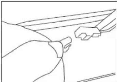
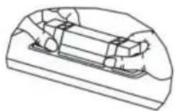
Light Replacement
- Remove the grease filter and carefully remove the 2 screws from the front plate (a cross headed screwdriver will be needed to remove the screws).
- Lower the control panel at the front by carefully pulling it downwards. You can now access the light module and terminals. Replace the lamp(commercially available LED lamp (max.1.5 W).
natural_image
Line drawing of a car seatbelt with attached bracket (no text or symbols)1

natural_image
Pure technical line drawing of a mechanical component or bracket (no text or symbols)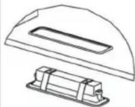
natural_image
Technical line drawing of a mechanical component with a curved top and rectangular base (no text or symbols)2
Replacement Light
| ∅ Max Power Voltage Picture | ILCOS D code | |||
| 33.2 x 120 mm | 1,5 W DC 12 V | 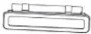 | DSS-1.5-S-33.2/120 | |
TROUBLESHOOTING
| Problem Cause Solution | ||
| Light on, but motor does not work | The blades are blocked. Check the blades. | |
| The capacitor is damaged. Replace capacitor. | ||
| The motor is damaged. Replace motor. | ||
| Both light and motor do not work | Apart from the above mentioned, check the following: | |
| Light damaged. Replace lights. | ||
| Power cord loose. Connect the wires as the electric diagram. | ||
| Oil leakage Outlet and the air ventilation entrance are not tightly sealed. | Take down the outlet and seal with glue. | |
| Vibration | The blade, if damaged, can cause vibrating. | Replace the blade. |
| The motor is not tightly fastened. | Fasten the motor tightly. | |
| The cooker hood is not tightly fixed. | Fixed the cooker hood tightly. | |
| Insufficient suction The distance between the cooker hood and the cooker top is too large. | Readjust the distance. | |
| Too much ventilation from open doors or windows. Choose a new place to install the appliance or close some doors / windows. | ||
| The machine inclines The fixing screws are not tight enough. | Tighten the fixing screw and make it horizontal. | |
| The hanging screws are not tight enough Tighten the hanging screw and make it horizontal. | ||
NOTES ON ENVIRONMENTAL PROTECTION
- During cooking, make sure that there is sufficient air supply so that the cooker hood can operate efficiently and with low operating noise.
- Adjust the fan speed to the amount of steam produced during cooking. Use the intensive mode only when necessary. The lower the fan speed, the less energy is consumed.
- If large amounts of steam are produced during cooking, select a higher fan speed in good time. If the cooking steam has already dispersed in the kitchen, the cooker hood must be operated longer.
- Switch off the cooker hood when you no longer need it.
- Switch off the lighting when you no longer need it.
- Clean the filter at regular intervals and replace it if necessary to increase the effectiveness of the ventilation system and prevent fire hazards.
• Always put the lid on when cooking to reduce cooking steam and condensation.
PRODUCT DATA SHEET
Information according to Regulation (EU) No. 65/2014
Measurement and calculation methods according to EN 61591:1997+A1:2006+A2:2011+A11:2014+A12:2015
| Item number | 10034258, 10034259, 10034260, 10034261 | ||
| Description Symbol Value Unit | |||
| Annual Energy Consumption AEC | hood | 25,9 kWh/Year | |
| Energy Efficiency class B | |||
| Fluid Dynamic Efficiency FDE | hood | 13,5 | |
| Fluid Dynamic Efficiency class D | |||
| Lighting Efficiency LE | hood | 54 Lux/W | |
| Lighting Efficiency class A | |||
| Grease Filtering Efficiency | GFBhood | 73,2 % | |
| Grease Filtering Efficiency class | D | ||
| air flow at minimum and maximum speed in normal use, intensive or boost excluded | 181,6 / 306,1 | m^3/h | |
| air flow at intensive or boost setting | - | m^3/h | |
| airborne acoustical A-weighted sound power emissions at minimum and maximum speed available in normal use | 54/65 | dB | |
| airborne acoustical A-weighted sound power emissions at intensive or boost setting | - | dB | |
| power consumption in off mode | Po | - | W |
| power consumption in standby mode | Ps | 0,49 | W |
| Contact details | Chal-Tec GmbH, Wallstraße 16, 10179, Berlin, Germany | ||
Information according to Regulation (EU) No. 66/2014
Measurement and calculation methods according to EN 61591:1997+A1:2006+A2:2011+A11:2014+A12:2015
| Item number | 10034258, 10034259, 10034260, 10034261 | ||
| Description Symbol Value Unit | |||
| Annual Energy Consumption AEC | hood | 25,9 kWh/Year | |
| Time increase factor f 1,5 | |||
| Fluid Dynamic Efficiency FDE | hood | 13,5 | |
| Energy Efficiency Index EEI | hood | 63 | |
| Measured air flow rate at best efficiency point | QBEP | 156,2 m3/h | |
| Measured air pressure at best efficiency point | PBEP | 143 | Pa |
| Maximum air flow Q | max | 306,1 | m3/h |
| Measured electric power input at best efficiency point | WBEP | 45,7 | W |
| Nominal power of the lighting system | WL | 1,3 | W |
| Average illumination of the lighting system on the cooking surface | Emiddle | 70 | Lux |
| Measured power consumption in standby mode | Po | 0,49 | W |
| Measured power consumption off mode | Ps | - | W |
| Sound power level | LWA | 65 | dB |
| Contact details | Chal-Tec GmbH, Wallstraße 16, 10179, Berlin, Germany | ||
DISPOSAL CONSIDERATIONS
natural_image
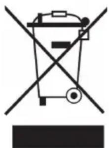
Symbol of a trash bin crossed with a diagonal line, no text or numbers presentIf there is a legal regulation for the disposal of electrical and electronic devices in your country, this symbol on the product or on the packaging indicates that this product must not be disposed of with household waste. Instead, it must be taken to a collection point for the recycling of electrical and electronic equipment. By disposing of it in accordance with the rules, you are protecting the environment and the health of your fellow human beings from negative consequences. For information about the recycling and disposal of this product, please contact your local authority or your household waste disposal service.
MANUFACTURER & IMPORTER (UK)
Manufacturer:
Chal-Tec GmbH, Wallstrasse 16, 10179 Berlin, Germany.
Importer for Great Britain:
Berlin Brands Group UK Limited
PO Box 42
272 Kensington High Street
London, W8 6ND
United Kingdom
Estimado cliente:
ÍNDICE
natural_image
Diagram of a computer case with an open lid and internal compartments, showing a directional arrow (no text or symbols present)
natural_image
Technical line drawing of a mechanical device with mounting bracket and internal components (no text or symbols)natural_image
Illustration of a hand inserting a device into a screen, showing a curved arrow (no text or symbols)natural_image
Pure mechanical diagram showing a rectangular frame with internal components and directional arrows, no text or symbols present.Retirar:
natural_image
Line drawing of a car seatbelt buckle and attached vehicle (no text or symbols)1
natural_image
Pure technical line drawing of a mechanical component or bracket (no text or symbols)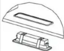
natural_image
Technical line drawing of a mechanical component with a curved top and rectangular base (no text or symbols)2
Luz de repuesto
natural_image
Symbol of a trash bin crossed with a diagonal line, no text or numbers presentBerlin Brands Group UK Limited
PO Box 42
272 Kensington High Street
London, W8 6ND
United Kingdom
Chère cliente, cher client,
SOMMAIRE
natural_image
Diagram of a device interior showing a front panel with a close-up view of the lid and internal components, connected to an arrow indicating direction (no text or symbols present)
natural_image
Technical line drawing of a mechanical device with mounting bracket and internal components (no text or symbols)natural_image
Illustration of a hand inserting a device into a tablet, showing a curved arrow (no text or symbols)natural_image
Pure mechanical diagram showing a rectangular frame with internal components and directional arrows, no text or symbols present.Démontage :
natural_image
Line drawing of a hand holding a car seatbelt, with a small bracket attached (no text or symbols)1
natural_image
Pure technical line drawing of a mechanical component or bracket (no text or symbols)
natural_image
Technical line drawing of a mechanical component with a curved top and rectangular base (no text or symbols)2
Ampoule de rechange
| ∅ Puissance Tension Schéma Code ILCOS D | ||||
| 33,2 x 120 mm | 1,5 W DC 12 V | 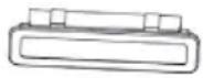 | DSS-1.5-S-33.2/120 | |
RÉSOLUTION DES PROBLÈMES
FICHE DE DONNÉES PRODUIT
natural_image
Symbol of a trash bin crossed with a diagonal line, no text or numbers presentBerlin Brands Group UK Limited
PO Box 42
272 Kensington High Street
London, W8 6ND
United Kingdom
Gentile cliente,
INDICE
natural_image
Diagram of a computer case with an open lid and internal compartments, showing a directional arrow (no text or symbols present)
natural_image
Technical line drawing of a mechanical device with mounting bracket and internal components (no text or symbols)natural_image
Illustration of a hand holding a smartphone with a finger pointing at it, showing a curved arrow (no text or symbols present)natural_image
Pure mechanical diagram showing a central component with symmetrical supports and directional arrows, no text or symbols present.Rimuovere:
natural_image
Line drawing of a car seatbelt with attached electrical plug (no text or symbols)1

natural_image
Pure technical line drawing of a mechanical component or bracket (no text or symbols)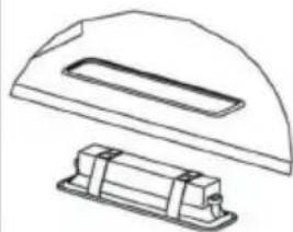
natural_image
Technical line drawing of a mechanical component with a curved top and rectangular base (no text or symbols)2
natural_image
Symbol of a trash bin crossed with a diagonal line, no text or labels presentPRODUTTORE E IMPORTATORE (UK)
Produttore:
Chal-Tec GmbH, Wallstraße 16, 10179 Berlino, Germania.
Berlin Brands Group UK Limited
PO Box 42
272 Kensington High Street
London, W8 6ND
United Kingdom
Geachte klant,
INHOUDSOPGAVE
INSTALLATIE ACCESSOIRES
natural_image
Diagram of a device interior showing a front panel with a close-up view of the lid and internal components, connected to an arrow indicating direction (no text or symbols present)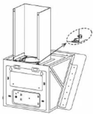
natural_image
Technical line drawing of a mechanical device with mounting bracket and internal components (no text or symbols)natural_image
Illustration of a hand inserting a device into a screen, showing a curved arrow (no text or symbols)natural_image
Pure mechanical diagram showing a central component with symmetrical arrows indicating rotational flow, no text or symbols present.Verwijderen:
natural_image
Line drawing of a car seatbelt buckle and rearview bracket (no text or symbols)1
natural_image
Pure technical line drawing of a mechanical component or bracket (no text or symbols)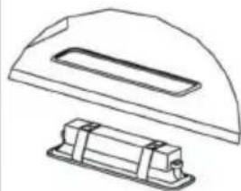
natural_image
Technical line drawing of a mechanical component with a curved top and rectangular base (no text or symbols)2
Reservelamp
INSTRUCTIES VOOR AFVALVERWERKING
natural_image
Symbol of a trash bin crossed with a diagonal line, no text or numbers presentBerlin Brands Group UK Limited
PO Box 42
272 Kensington High Street
London, W8 6ND
United Kingdom

area
| Category | Value | |---|---| | 1 | 100 | | 2 | 100 | | 3 | 100 | | 4 | 100 | | 5 | 100 | | 6 | 100 | | 7 | 100 | | 8 | 100 | | 9 | 100 | | 10 | 100 | | 11 | 100 | | 12 | 100 | | 13 | 100 | | 14 | 100 | | 15 | 100 | | 16 | 100 | | 17 | 100 | | 18 | 100 | | 19 | 100 | | 20 | 100 | | 21 | 100 | | 22 | 100 | | 23 | 100 | | 24 | 100 | | 25 | 100 | | 26 | 100 | | 27 | 100 | | 28 | 100 | | 29 | 100 | | 30 | 100 | | 31 | 100 | | 32 | 100 | | 33 | 100 | | 34 | 100 | | 35 | 100 | | 36 | 100 | | 37 | 100 | | 38 | 100 | | 39 | 100 | | 40 | 100 | | 41 | 100 | | 42 | 100 | | 43 | 100 | | 44 | 100 | | 45 | 100 | | 46 | 100 | | 47 | 100 | | 48 | 100 | | 49 | 100 | | 50 | 100 | | 51 | 100 | | 52 | 100 | | 53 | 100 | | 54 | 100 | | 55 | 100 | | 56 | 100 | | 57 | 100 | | 58 | 100 | | 59 | 100 | | 60 | 100 | | 61 | 100 | | 62 | 100 | | 63 | 100 | | 64 | 100 | | 65 | 100 | | 66 | 100 | | 67 | 100 | | 68 | 100 | | 69 | 100 | | 70 | 100 | | 71 | 100 | | 72 | 100 | | 73 | 100 | | 74 | 100 | | 75 | 100 | | 76 | 100 | | 77 | 100 | | 78 | 100 | | 79 | 100 | | 80 | 100 | | 81 | 100 | | 82 | 100 | | 83 | 100 | | 84 | 100 | | 85 | 100 | | 86 | 100 | | 87 | 100 | | 88 | 100 | | 89 | 100 | | 90 | 100 | | 91 | 100 | | 92 | 100 | | 93 | 100 | | 94 | 100 | | 95 | 100 | | 96 | 100 | | 97 | 100 | | 98 | 100 | | 99 | 100 | | Note: The actual values in the 'Value' column are not provided in the code. I have used the label 'The Region' to represent the 'Region'. The values are estimated based on the provided code.
KLARSTEIN

- INHALTSVERZEICHNIS
- INSTALLATIONSZUBEHÖR
- Aktivkohlefilter (Umluftversion)
- Entfernen:
- Ersatzlicht
- Dear Customer,
- CONTENTS
- TECHNICAL DATA
- SAFETY INSTRUCTIONS
- Important notes about the extraction mode
- WARNING
- Important note on disassembly of the device
- PRODUCT OVERVIEW
- INSTALLATION COMPONENTS
- DIMENSIONS
- INSTALLATION
- Wall Drilling and Bracket Fixing
- Mark Points
- Fix the Brackets (Optional)
- Hook the Hood Body
- Connections to Ducted Version Air Exhaust System
- CHIMNEY ASSEMBLY
- KEY FUNCTIONS
- CARE AND CLEANING
- Grease Filters
- Activated carbon filter (circulating air version)
- Fix:
- Remove:
- Light Replacement
- Replacement Light
- TROUBLESHOOTING
- NOTES ON ENVIRONMENTAL PROTECTION
- PRODUCT DATA SHEET
- Information according to Regulation (EU) No. 65/2014
- Information according to Regulation (EU) No. 66/2014
- DISPOSAL CONSIDERATIONS
- MANUFACTURER & IMPORTER (UK)
- Manufacturer:
- Importer for Great Britain:
- Estimado cliente:
- ÍNDICE
- Retirar:
- Chère cliente, cher client,
- SOMMAIRE
- Démontage :
- Ampoule de rechange
- FICHE DE DONNÉES PRODUIT
- Gentile cliente,
- INDICE
- Rimuovere:
- PRODUTTORE E IMPORTATORE (UK)
- Produttore:
- Geachte klant,
- INHOUDSOPGAVE
- INSTALLATIE ACCESSOIRES
- Verwijderen:
- Reservelamp
- INSTRUCTIES VOOR AFVALVERWERKING
- KLARSTEIN
Brand : Klarstein
Model : Sofia 60
Category : Range hood