
CMEM2500 - Saw Craftsman - Free user manual and instructions
Find the device manual for free CMEM2500 Craftsman in PDF.

| Device type | Cut-off saw (abrasive cut) |
| Brand | Craftsman |
| Model | CMEM2500 |
| Supply voltage | 120 V~ |
| Frequency | 50/60 Hz |
| Rated current | 15 A |
| No-load speed | 3800 RPM |
| Wheel diameter | 355 mm (14 in) |
| Wheel thickness | 3 mm (0.1 in) |
| Arbor diameter (bore) | 25.4 mm (1 in) |
| Net weight | 15.5 kg (34.1 lbs) |
| Cutting capacity at 90° (rectangular piece) | 125 mm (height) x 130 mm (width) |
| Cutting capacity at 45° (rectangular piece) | 95 mm (height) x 105 mm (width) |
| Recommended wheel type | Reinforced bonded or diamond wheel, Ø 355 mm, bore 25.4 mm |
| Cuttable materials | Steel (do not cut magnesium or wood) |
| Safety protection | Wheel guard, spark deflector, arbor lock |
| Required protective equipment | Safety goggles (ANSI Z87.1), hearing protection, dust mask |
| Maintenance | Clean vents with compressed air, inspect motor brushes every 8 mm of wear |
| Warranty | 3-year limited + 90-day satisfaction guarantee |
| Customer service number | 1-888-331-4569 |
Frequently Asked Questions - CMEM2500 Craftsman
User questions about CMEM2500 Craftsman
0 question about this device. Answer the ones you know or ask your own.
Ask a new question about this device
Download the instructions for your Saw in PDF format for free! Find your manual CMEM2500 - Craftsman and take your electronic device back in hand. On this page are published all the documents necessary for the use of your device. CMEM2500 by Craftsman.
USER MANUAL CMEM2500 Craftsman
IF YOU HAVE QUESTIONS OR COMMENTS, CONTACT US.
POUR TOUTE QUESTION OU TOUT COMMENTAIRE, NOUS CONTACTER.
SI TIENE DUDAS O COMENTARIOS, CONTÁCTENOS.
1-888-331-4569 WWW.CRAFTSMAN.COM
English (original instructions) 1
Definitions: Safety Alert Symbols and Words
This instruction manual uses the following safety alert symbols and words to alert you to hazardous situations and your risk of personal injury or property damage.
DANGER: Indicates an imminently hazardous situation which, if not avoided, will result in death or serious injury.
WARNING: Indicates a potentially hazardous situation which, if not avoided, could result in death or serious injury.
CAPTION: Indicates a potentially hazardous situation which, if not avoided, may result in minor or moderate injury.
(Used without word) Indicates a safety related message.
NOTICE: Indicates a practice not related to personal injury which, if not avoided, may result in property damage.
Fig. A
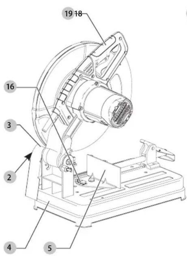

1 Lock pin
2 Spark deflector screw
3 Spark deflector
4 Base
5 Fence
6 Vise
7 5/16" hex wrench
8 Crank
9 Vise lever
10 Wheel
11 Guard
12 Spindle lock
13 Trigger switch
14 Depth stop bolt and jam nut
15 Padlock hole
16 Fence bolts
17 Mounting holes
18 Lift and carry handle
19 Switch handle/grasping area
WARNING: Read all safety warnings and all
instructions. Failure to follow the warnings and instructions may result in electric shock, fire and/or serious injury.

WARNING: To reduce the risk of injury, read the instruction manual.
If you have any questions or comments about this or any product, call CRAFTSMAN toll free at: 1-888-331-4569.
14" Chop Saw
CMEM2500
GENERAL POWER TOOL SAFETY WARNINGS
WARNING: Read all safety warnings, instructions, illustrations and specifications provided with this power tool. Failure to follow all instructions listed below may result in electric shock, fire and/or serious injury.
SAVE ALL WARNINGS AND INSTRUCTIONS FOR FUTURE REFERENCE.
The term "power tool" in the warnings refers to your mains-operated (corded) power tool or battery-operated (cordless) power tool.
1) Work Area Safety
a) Keep work area clean and well lit. Cluttered or dark areas invite accidents.
b) Do not operate power tools in explosive atmospheres, such as in the presence of flammable liquids, gases or dust. Power tools create sparks which may ignite the dust or fumes.
c) Keep children and bystanders away while operating a power tool. Distractions can cause you to lose control.
2) Electrical Safety
a) Power tool plugs must match the outlet. Never modify the plug in any way. Do not use any adapter plugs with earthed (grounded) power tools. Unmodified plugs and matching outlets will reduce risk of electric shock.
b) Avoid body contact with earthed or grounded surfaces, such as pipes, radiators, ranges and refrigerators. There is an increased risk of electric shock if your body is earthed or grounded.
c) Do not expose power tools to rain or wet conditions. Water entering a power tool will increase the risk of electric shock.
d) Do not abuse the cord. Never use the cord for carrying, pulling or unplugging the power tool. Keep cord away from heat, oil, sharp edges or moving parts. Damaged or entangled cords increase the risk of electric shock.
e) When operating a power tool outdoors, use an extension cord suitable for outdoor use. Use of a cord suitable for outdoor use reduces the risk of electric shock.
f) If operating a power tool in a damp location is unavoidable, use a ground fault circuit interrupter (GFCI) protected supply. Use of a GFCI reduces the risk of electric shock.
3) Personal Safety
a) Stay alert, watch what you are doing and use common sense when operating a power tool. Do not use a power tool while you are tired or under the influence of drugs, alcohol or medication. A
moment of inattention while operating power tools may result in serious personal injury.
b) Use personal protective equipment. Always wear eye protection. Protective equipment such as a dust mask, non-skid safety shoes, hard hat, or hearing protection used for appropriate conditions will reduce personal injuries.
c) Prevent unintentional starting. Ensure the switch is in the off-position before connecting to power source and/or battery pack, picking up or carrying the tool. Carrying power tools with your finger on the switch or energizing power tools that have the switch on invites accidents.
d) Remove any adjusting key or wrench before turning the power tool on. A wrench or a key left attached to a rotating part of the power tool may result in personal injury.
e) Do not overreach. Keep proper footing and balance at all times. This enables better control of the power tool in unexpected situations.
f) Dress properly. Do not wear loose clothing or jewelry. Keep your hair, clothing and gloves away from moving parts. Loose clothes, jewelry or long hair can be caught in moving parts.
g) If devices are provided for the connection of dust extraction and collection facilities, ensure these are connected and properly used. Use of dust collection can reduce dust-related hazards.
h) Do not let familiarity gained from frequent use of tools allow you to become complacent and ignore tool safety principles. A careless action can cause severe injury within a fraction of a second.
4) Power Tool Use and Care
a) Do not force the power tool. Use the correct power tool for your application. The correct power tool will do the job better and safer at the rate for which it was designed.
b) Do not use the power tool if the switch does not turn it on and off. Any power tool that cannot be controlled with the switch is dangerous and must be repaired.
c) Disconnect the plug from the power source and/or remove the battery pack, if detachable, from the power tool before making any adjustments, changing accessories, or storing power tools. Such preventive safety measures reduce the risk of starting the power tool accidentally.
d) Store idle power tools out of the reach of children and do not allow persons unfamiliar with the power tool or these instructions to operate the power tool. Power tools are dangerous in the hands of untrained users.
e) Maintain power tools and accessories. Check for misalignment or binding of moving parts, breakage of parts and any other condition that may affect the power tool's operation. If
English
damaged, have the power tool repaired before use. Many accidents are caused by poorly maintained power tools.
f) Keep cutting tools sharp and clean. Properly maintained cutting tools with sharp cutting edges are less likely to bind and are easier to control.
g) Use the power tool, accessories and tool bits etc. in accordance with these instructions, taking into account the working conditions and the work to be performed. Use of the power tool for operations different from those intended could result in a hazardous situation.
h) Keep handles and grasping surfaces dry, clean and free from oil and grease. Slippery handles and grasping surfaces do not allow for safe handling and control of the tool in unexpected situations.
5) Service
a) Have your power tool serviced by a qualified repair person using only identical replacement parts. This will ensure that the safety of the power tool is maintained.
Safety Instructions for Cut-Off Machines
1) Cut-Off Machine Safety Warnings
- Position yourself and bystanders away from the plane of the rotating wheel. The guard helps to protect the operator from broken wheel fragments and accidental contact with wheel.
- Use only bonded reinforced wheels for your power tool. Just because an accessory can be attached to your power tool, it does not assure safe operation.
- The rated speed of the accessory must be at least equal to the maximum speed marked on the power tool. Accessories running faster than their rated speed can break and fly apart.
- Wheels must be used only for recommended applications. For example: do not grind with the side of a cut-off wheel. Abrasive cut-off wheels are intended for peripheral grinding, side forces applied to these wheels may cause them to shatter.
• Always use undamaged wheel flanges that are of correct diameter for your selected wheel. Proper wheel flanges support the wheel thus reducing the possibility of wheel breakage. - The outside diameter and the thickness of your accessory must be within the capacity rating of your power tool. Incorrectly sized accessories cannot be adequately guarded or controlled.
- The arbour size of wheels and flanges must properly fit the spindle of the power tool. Wheels and flanges with arbour holes that do not match the mounting hardware of the power tool will run out of balance, vibrate excessively and may cause loss of control.
- Do not use damaged wheels. Before each use, inspect the wheels for chips and cracks. If the power tool or wheel is dropped, inspect for damage or install an undamaged wheel. After inspecting and installing the wheel, position
yourself and bystanders away from the plane of the rotating wheel and run the power tool at maximum no load speed for one minute. Damaged wheels will normally break apart during this test time.
- Wear personal protective equipment. Depending on application, use face shield, safety goggles or safety glasses. As appropriate, wear dust mask, hearing protectors, gloves and shop apron capable of stopping small abrasive or workpiece fragments. The eye protection must be capable of stopping flying debris generated by various operations. The dust mask or respirator must be capable of filtrating particles generated by your operation. Prolonged exposure to high intensity noise may cause hearing loss.
- Keep bystanders a safe distance away from work area. Anyone entering the work area must wear personal protective equipment. Fragments of workpiece or of a broken wheel may fly away and cause injury beyond immediate area of operation.
- Position the cord clear of the spinning accessory. If you lose control, the cord may be cut or snagged and your hand or arm may be pulled into the spinning wheel.
- Regularly clean the power tool's air vents. The motor's fan can draw the dust inside the housing and excessive accumulation of powdered metal may cause electrical hazards.
- Do not operate the power tool near flammable materials. Do not operate the power tool while placed on a combustible surface such as wood. Sparks could ignite these materials.
- Do not use accessories that require liquid coolants. Using water or other liquid coolants may result in electrocution or shock.
2) Kickback and Related Warnings
Kickback is a sudden reaction to a pinched or snagged rotating wheel. Pinching or snagging causes rapid stalling of the rotating wheel which in turn causes the uncontrolled cutting unit to be forced upwards toward the operator.
For example, if an abrasive wheel is snagged or pinched by the workpiece, the edge of the wheel that is entering into the pinch point can dig into the surface of the material causing the wheel to climb out or kick out. Abrasive wheels may also break under these conditions.
Kickback is the result of power tool misuse and/or incorrect operating procedures or conditions and can be avoided by taking proper precautions as given below.
- Maintain a firm grip on the power tool and position your body and arm to allow you to resist kickback forces. The operator can control upward kickback forces, if proper precautions are taken.
- Do not position your body in line with the rotating wheel. If kickback occurs, it will propel the cutting unit upwards toward the operator.
- Do not attach a saw chain, woodcarving blade, segmented diamond wheel or toothed saw blade. Such blades create frequent kickback and loss of control.
ENGLISH
- Do not "jam" the wheel or apply excessive pressure. Do not attempt to make an excessive depth of cut. Overstressing the wheel increases the loading and susceptibility to twisting or binding of the wheel in the cut and the possibility of kickback or wheel breakage.
- When the wheel is binding or when interrupting a cut for any reason, switch off the power tool and hold the cutting unit motionless until the wheel comes to a complete stop. Never attempt to remove the wheel from the cut while the wheel is in motion otherwise kickback may occur. Investigate and take corrective action to eliminate the cause of wheel binding.
- Do not restart the cutting operation in the workpiece. Let the wheel reach full speed and carefully re-enter the cut. The wheel may bind, walk up or kickback if the power tool is restarted in the workpiece.
- Support any oversized workpiece to minimize the risk of wheel pinching and kickback. Large workpieces tend to sag under their own weight. Supports must be placed under the workpiece near the line of cut and near the edge of the workpiece on both sides of the wheel.
Additional Safety Information
WARNING: Never modify the power tool or any part of it. Damage or personal injury could result.
WARNING: ALWAYS use safety glasses. Everyday eyeglasses are NOT safety glasses. Also use face or dust mask if operation is dusty. ALWAYS WEAR CERTIFIED SAFETY EQUIPMENT:
• ANSI Z87.1 eye protection (CAN/CSA Z94.3),
• ANSI S12.6 (S3.19) hearing protection,
• NIOSH/OSHA/MSHA respiratory protection.
WARNING: Some dust created by power sanding, sowing, grinding, drilling, and other construction activities contains chemicals known to the State of California to cause cancer, birth defects or other reproductive harm. Some examples of these chemicals are:
- lead from lead-based paints,
• crystalline silica from bricks and cement and other masonry products, and
• arsenic and chromium from chemically-treated lumber.
Your risk from these exposures varies, depending on how often you do this type of work. To reduce your exposure to these chemicals: work in a well ventilated area, and work with approved safety equipment, such as those dust masks that are specially designed to filter out microscopic particles.
- Avoid prolonged contact with dust from power sanding, sawing, grinding, drilling, and other construction activities. Wear protective clothing and wash exposed areas with soap and water. Allowing dust to get into your mouth, eyes, or lay on the skin may promote absorption of harmful chemicals.
WARNING: Use of this tool can generate and/or disperse dust, which may cause serious and
permanent respiratory or other injury. Always use NIOSH/OSHA approved respiratory protection appropriate for the dust exposure. Direct particles away from face and body.
WARNING: Always wear proper personal hearing protection that conforms to ANSI S12.6 (S3.19)
during use. Under some conditions and duration of use, noise from this product may contribute to hearing loss.
CAUTION: When not in use, place tool on its side on a stable surface where it will not cause a tripping or falling hazard. Some tools will stand upright but may be easily knocked over.
• Air vents often cover moving parts and should be avoided. Loose clothes, jewelry or long hair can be caught in moving parts.
- An extension cord must have adequate wire size (AWG or American Wire Gauge) for safety. The smaller the gauge number of the wire, the greater the capacity of the cable, that is, 16 gauge has more capacity than 18 gauge. An undersized cord will cause a drop in line voltage resulting in loss of power and overheating. When using more than one extension to make up the total length, be sure each individual extension contains at least the minimum wire size. The following table shows the correct size to use depending on cord length and nameplate ampere rating. If in doubt, use the next heavier gauge. The lower the gauge number, the heavier the cord.
Minimum Gauge for Cord Sets
| Volts | Total Length of Cord in Feet (meters) | ||||
| 120V 25 (7.6) | 50 (15.2) | 100 (30.5) | 150 (45.7) | ||
| 240V 50 (15.2) | 100 (30.5) | 200 (61.0) | 300 (91.4) | ||
| Ampere Rating | American Wire Gauge | ||||
| More Than | Not More Than | ||||
| 0 6 18 | 16 16 14 | ||||
| 6 10 | 18 16 14 12 | ||||
| 10 12 | 16 16 14 12 | ||||
| 12 16 | 14 12 Not Recommended | ||||
The label on your tool may include the following symbols. The symbols and their definitions are as follows:
V....volts SPM....strokes per minute
Hz....hertz OPM....oscillationsper
min......minutes minute
or DC.....direct current A.....amperes
Class I Construction W.....watts
(grounded) \~ or AC......alternating current
.../min.....per minute ≈ or AC/DC....alternatingor
BPM.....beats per minute direct current
IPM....impacts per minute ☐....ClassII
RPM......revolutionsper minute Construction (double insulated)
sfpm ____ surface feet per n_0 ____ no load speed
minute n....rated speed
earthing terminal


SAVE THESE INSTRUCTIONS FOR FUTURE USE
Motor
Be sure your power supply agrees with the nameplate marking. Voltage decrease of more than 10% will cause loss of power and overheating. These tools are factory tested; if this tool does not operate, check power supply.
ASSEMBLY AND ADJUSTMENTS
WARNING: To reduce the risk of serious personal injury, turn unit off and disconnect it from power source before making any adjustments or removing/installing attachments or accessories.
An accidental start-up can cause injury.
Intended Use
Your chop saw has been designed for the cutting of variously shaped steel materials. It is designed only for use with reinforced bonded abrasives. Diamond or TCT or toothed blades should not be used with this unit.
DO nOT use under wet conditions or in presence of flammable liquids or gases.
Your chop saw is a professional power tool.
DO nOT let children come into contact with the tool. Supervision is required when inexperienced operators use this tool.
SPECIFICATIONS
CMEM2500
| Voltage 120V~ |
| Frequency 50/60 Hz |
| Power input 15 amp |
| No-load speed 3800/min (rpm) |
| Wheel diameter 14" (355 mm) |
| Wheel thickness 0.1" (3 mm) |
| Net weight 34.1 lbs (15.5 kg) |
| Bore diameter 1" (25.4 mm) |
Cutting Capacity
The wide vise opening and high pivot point provide cutting capacity for many large pieces. Use the cutting capacity chart to determine total maximum size of cuts that can be made with a new wheel.
CAUTION: Certain large, circular or irregularly shaped shapes may require additional holding means if they cannot be held securely in vise.
CAUTION: Do not cut magnesium or wood with t#ol.
Maximum Cutting Capacity
NOTE: Capacity shown on chart assumes no wheel wear and optimum fence position.
| Workpiece Shape | ||||
| 90° Cutting angle | A = 4-7/8" (125 mm) | A = 4-1/2" (115 mm) | 4-1/2" x 5-1/8" (115 mm x 130 mm) | A = 4-3/4" (120 mm) |
| 45° Cutting angle | A = 4-1/2" (115 mm) | A = 3-13/16" (98 mm) | 3-3/4" x 4-1/8" (95 mm x 105 mm) | A = 4-1/8" (105 mm) |
OPERATION
WARNING: To reduce the risk of serious personal injury, turn unit off and disconnect it from power source before making any adjustments or removing/installing attachments or accessories.
An accidental start-up can cause injury.
Lifting and Transporting the Chop Saw (Fig. A)
Fold down unit to position where you can carry the saw. Push in lock pin 1 to lock arm down. Lift and carry using the lift and carry handle 18.
Unlocking (Fig. A)
To unlock tool and raise head, depress motor arm slightly and pull lock pin 1 out. Motor arm will then pivot upward.
Mounting (Fig. A)
CAUTION: Tool must be supported on stable, level, non-skid surface to prevent unexpected movement when operating.
- Drill holes through the work surface that align the base of the chop saw.
- Insert four M10 screws down through the mounting holes 17 in the base and through holes in mounting surface. The approximate length of the screws should be the thickness of the mounting surface plus 4" (102 mm).
Spark Deflector Adjustment (Fig. A)
To best deflect sparks away from surrounding persons and materials, loosen the spark deflector screw 2, adjust the spark deflector 3 and then retighten screw. Do not allow cordset to come into contact with deflector or sparks as damage to cordset may occur.
Depth Stop (Fig. A)
Depth stop is set at the factory for a new 14" (355 mm) wheel to prevent wheel from cutting into the supporting surface. To allow more depth of cut, use a wrench (not provided) to loosen the depth stop bolt and jam nut 14 and raise bolt to desired height and then turn jam nut clockwise until seated firmly on the casting. Securely tighten the depth stop bolt before use.
English
CAUTION: When changing to a new wheel, readjust stop to original position to prevent cutting into supporting surface.
Trigger Switch (Fig. A)
To start the tool, depress the trigger switch 13. To turn the tool off, release the trigger switch. Keep hands and material from wheel until it has coasted to a stop. To prevent unauthorized use of tool, install a standard padlock (not included) into the padlock hole 15 located in the trigger.
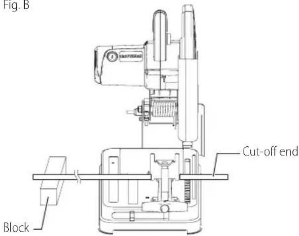
Material Clamping and Supporting (Fig. B)
- Angles are best clamped and cut with both legs resting against base.
- A spacer block slightly narrower than the work piece can be used to increase wheel utilization.
- Long workpieces must be supported by a block so it will be level with top of base (Fig. B). The cut off end should be free to fall downward to avoid wheel binding.
Fig. B
Vise Operation (Fig. A)
The vise 6 has a quick-travel feature. To release the vise when it is clamped tightly, turn the crank 8 counterclockwise one or two times to remove clamping pressure. Lift vise lever 9 up. Pull crank assembly out as far as desired. Vise may be pushed forward into work without cranking. Lower vise lever then tighten vise 6 on work by using crank.
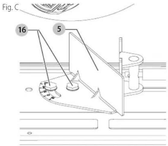
Fence Operation (Fig. A, C)
WARNING: Turn off and unplug the tool before removing any adjustments or removing or installing attachments or accessories. Be sure the trigger switch is in the OFF position.
The fence 5 can be adjusted two ways: to change desired cutting angle and to change spacing between the fence and vise.
To Change Spacing Between the Fence and Vise
Using the 5/16" (8 mm) hex wrench 7 provided, loosen and remove the two fence bolts 16. Adjust the fence 5 to desired locations. Insert both fence bolts in provided locations. Securely tighten both fence bolts before use.
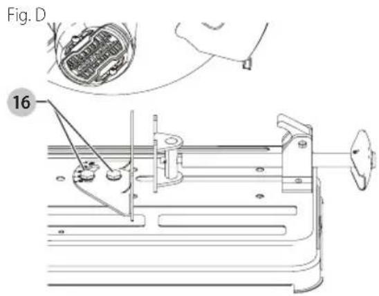
To Change the Desired Cutting Angle (Fig. A, D)
Use the 5/16" hex wrench 7 provided to loosen (do not remove) the two fence bolts 16. Align the desired angle indicator line with the slot line in the base 4. Securely tighten both fence bolts before use. For more accurate square cuts, disconnect the power supply, loosen the two fence bolts, push arm down until wheel extends into base. Place a square against the wheel and adjust fence against the square. Securely tighten both fence bolts before use. When making a miter cut, the vise 6 may not clamp securely, depending on the thickness of the workpiece and the miter angle. Other aids (such as spring, bar or C-clamps) will be necessary to secure the work piece to the fence when making these cuts.
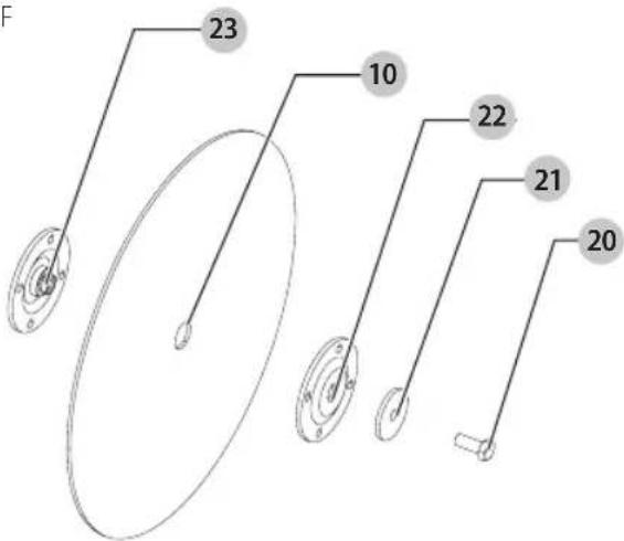
Removal and Installation of Wheels (Fig. A, E, F)
WARNING: Turn off and unplug the tool before making any adjustments or removing or installing attachments or accessories. Be sure the
trigger switch is in the OFF position. Do not make any adjustment while the wheel is in motion. Do not make any adjustment while chop saw is plugged into power supply.
- Push in spindle lock 12 and rotate wheel 10 by hand until wheel lock lever engages slot in inside flange 23 to lock wheel. Loosen the bolt 20 counterclockwise in the center of the abrasive wheel with the 5/16" (8 mm) hex wrench 7. Bolt has right-hand thread.
- Remove the bolt, washer 21, outside flange 22 and old wheel.
Fig. B
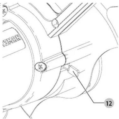
Fig. F
- Make sure flange surfaces are clean and flat. Install the new abrasive wheel by reversing the above steps.
- Do not overtighten bolt.
WARNING: Check the work surface that the chop saw when replacing with a new abrasive wheel. It is possible that the wheel may contact ANY ITEMS OR STRUCTURE THAT EXTENDS ABOVE work surface (under the base) when the arm is fully lowered.
WARNING: Always keep the screw attached to the guard and make sure the center guard in the right position after replacing wheel and before use, to protect user from high speed rotating wheel.
CAUTION: Only use 14" (335 mm) Type 1/41 wheels with 14" (25.4 mm) arbor hole with this tool. Never force a wheel onto the machine or alter the size of the arbor hole.
Operation Tips for More Accurate Cuts
- Allow the wheel to do the cutting. Excessive force will cause the wheel to glaze reducing cutting efficiency and/or to deflect causing inaccurate cuts.
• Properly adjust fence angle.
• Make sure material is laying flat across base.
• Properly clamp material to avoid movement and vibration.
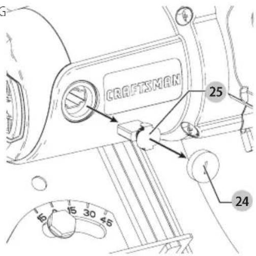
Motor Brush Inspection and Replacement (Fig. G, H)
WARNING: To reduce the risk of injury, turn unit and disconnect machine from power source before installing and removing accessories, before adjusting or changing set-ups or when making repairs. Be sure the trigger switch is in the OFF position. An accidental start-up can cause injury.
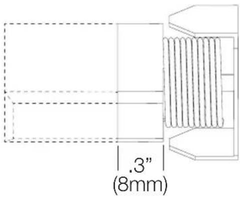
BE SURE TOOL IS UNPLUGGED BEFORE INSPECTING BRUSHES. Brushes should be regularly inspected for wear. To inspect brushes, remove brush cap 24.
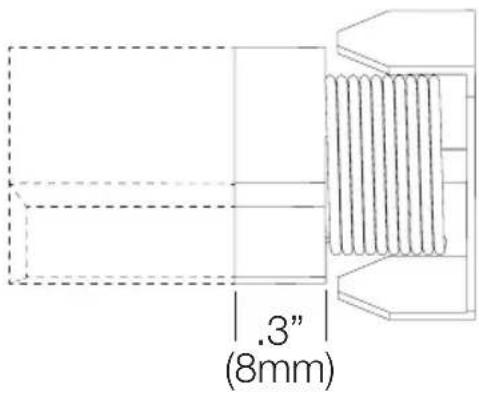
Brushes 25 should slide freely in brush box. If brushes are worn down to 0.3" (8 mm) as shown in Figure H they should be replaced. To reinstall, push new brush back into brush box. If replacing existing brush, maintain same orientation as when removed. Replace the brush cap (do not overtighten).
Fig. G
ENGLISH
Fig. H

Tool Care
Avoid overloading the machine. Overloading will result in a considerable reduction in speed and efficiency and the unit will become hot. In this event, run the machine at no load for a minute or two until cooled to normal working temperature by the built in fan. Switching your machine on and off whilst under load will considerably reduce the life of the switch.
MAINTENANCE
WARNING: To reduce the risk of serious personal injury, turn unit off and disconnect it from power source before making any adjustments or removing/installing attachments or accessories. An accidental start-up can cause injury.
Cleaning
WARNING: Blow dirt and dust out of all air vents with dry air at least once a week. To minimize the risk of eye injury, always wear ANSI Z87.1 approved eye protection when performing this procedure.
WARNING: Never use solvents or other harsh chemicals for cleaning the non-metallic parts of the tool. These chemicals may weaken the plastic materials used in these parts. Use a cloth dampened only with water and mild soap. Never let any liquid get inside the tool; never immerse any part of the tool into a liquid.
Accessories
WARNING: Since accessories, other than those offered by CRAFTSMAN, have not been tested with this product, use of such accessories with this tool could be hazardous. To reduce the risk of injury, only CRAFTSMAN recommended accessories should be used with this product.
Recommended accessories for use with your tool are available at extra cost from your local dealer or authorized service center. If you need assistance in locating any accessory, please contact CRAFTSMAN 1-888-331-4569.
WARNING: Handle and store all abrasive wheels carefully to prevent damage from thermal shock, heat, mechanical damage, etc. Store in a dry protected area free from high humidity, freezing temperatures or extreme temperature changes.
| ACCESSORIES CHART | |||
| Wheel Diameter | Wheel Thickness Bore | Diameter | |
| Cutting Wheel 14" (355 mm) n/a 1" | (25.4 mm) | ||
Repairs
WARNING: To assure product SAFETY and REELIBILITY, repairs, maintenance and adjustment (including power cord repairs, and brush inspection and replacement, when applicable) should be performed by a CRAFTSMAN factory service center or a CRAFTSMAN authorized service center. Always use identical replacement parts.
Register Online
Thank you for your purchase. Register your product now for:
- WARRANTY SERVICE: Registering your product will help you obtain more efficient warranty service in case there is a problem with your product.
- CONFIRMATION OF OWNERSHIP: In case of an insurance loss, such as fire, flood or theft, your registration of ownership will serve as your proof of purchase.
• FOR YOUR SAFETY: Registering your product will allow us to contact you in the unlikely event a safety notification is required under the Federal Consumer Safety Act.
• Register online at www.craftsman.com/
Three Year Limited Warranty
CRAFTSMAN will repair or replace, without charge, any defects due to faulty materials or workmanship for three years from the date of purchase. This warranty does not cover part failure due to normal wear or tool abuse. For further detail of warranty coverage and warranty repair information, visit www.craftsman.com or call
1-888-331-4569. This warranty does not apply to accessories or damage caused where repairs have been made or attempted by others. THIS LIMITED WARRANTY IS GIVEN IN LIEU OF ALL OTHERS, INCLUDING THE IMPLIED WARRANTY OF MERCHANTABILITY AND FITNESS FOR A PARTICULAR PURPOSE, AND EXCLUDES ALL INCIDENTAL OR CONSEQUENTIAL DAMAGES. Some states do not allow limitations on how long an implied warranty lasts or the exclusion or limitation of incidental or consequential damages, so these limitations may not apply to you. This warranty gives you specific legal rights and you may have other rights which vary in certain states or provinces.
90 DAY MONEY BACK GUARANTEE
If you are not completely satisfied with the performance of your CRAFTSMAN Power Tool or Nailer for any reason, you
can return it within 90 days from the date of purchase with a receipt for a full refund – no questions asked.
IATin AMERiCA: This warranty does not apply to products sold in Latin America. For products sold in Latin America, see country specific warranty information contained in the packaging, call the local company or see website for warranty information.
FREE WARning IABEI REPIACEMENT: If your warning labels become illegible or are missing, call 1-888-331-4569 for a free replacement.
minute Protection auditive
OPM....oscillations por minuto ....lire toute la documentation
A.....ampères
IPXX...... symbole IP
CONSERVER CES CONSIGNES POUR UTILISATION ULTÉRIEURE
Moteur
FRANÇAIS
Fig. H
ESPAÑOL
Fig. H
Eje Central Lázaro Cárdenas No. 18 - Local (55) 5588 9377 D, Col. Obrera
MERIDA, YUC
Calle 63 #459-A - Col. Centro (999) 928 5038
MONTERREY, N.L.
Av. Francisco I. Madero 831 Poniente - Col. (818) 375 23 13 Centro
PUEBLA, PUE
17 Norte #205 - Col. Centro (222) 246 3714
QUERETARO, QRO
Av. San Roque 274 - Col. San Gregorio (442) 2 17 63 14
SAN LUIS POTOSI, SLP

- Definitions: Safety Alert Symbols and Words
- WARNING: Read all safety warnings and all
- 14" Chop Saw
- CMEM2500
- GENERAL POWER TOOL SAFETY WARNINGS
- SAVE ALL WARNINGS AND INSTRUCTIONS FOR FUTURE REFERENCE.
- 1) Work Area Safety
- 2) Electrical Safety
- 3) Personal Safety
- 4) Power Tool Use and Care
- English
- 5) Service
- Safety Instructions for Cut-Off Machines
- 1) Cut-Off Machine Safety Warnings
- 2) Kickback and Related Warnings
- Additional Safety Information
- WARNING: Always wear proper personal hearing protection that conforms to ANSI S12.6 (S3.19)
- SAVE THESE INSTRUCTIONS FOR FUTURE USE
- Motor
- ASSEMBLY AND ADJUSTMENTS
- Intended Use
- Cutting Capacity
- Maximum Cutting Capacity
- OPERATION
- Lifting and Transporting the Chop Saw (Fig. A)
- Unlocking (Fig. A)
- Mounting (Fig. A)
- Spark Deflector Adjustment (Fig. A)
- Depth Stop (Fig. A)
- Trigger Switch (Fig. A)
- Material Clamping and Supporting (Fig. B)
- Vise Operation (Fig. A)
- Fence Operation (Fig. A, C)
- To Change Spacing Between the Fence and Vise
- To Change the Desired Cutting Angle (Fig. A, D)
- Removal and Installation of Wheels (Fig. A, E, F)
- Operation Tips for More Accurate Cuts
- Motor Brush Inspection and Replacement (Fig. G, H)
- Tool Care
- MAINTENANCE
- Cleaning
- Accessories
- Repairs
- Register Online
- Three Year Limited Warranty
- DAY MONEY BACK GUARANTEE
- CONSERVER CES CONSIGNES POUR UTILISATION ULTÉRIEURE
- Moteur
- FRANÇAIS
- ESPAÑOL
- MERIDA, YUC
- MONTERREY, N.L.
- PUEBLA, PUE
- QUERETARO, QRO
- SAN LUIS POTOSI, SLP
Brand : Craftsman
Model : CMEM2500
Category : Saw