
917.299011 - Saw Craftsman - Free user manual and instructions
Find the device manual for free 917.299011 Craftsman in PDF.

| Product Type | Garden Tiller |
| Brand | Craftsman |
| Model | 917.299011 |
| Engine Model | LCT PLMHK14600124P-BPQE2 |
| Fuel Type | Unleaded Regular Gasoline (87 octane min) |
| Fuel Capacity | 3 quarts (2.8 L) |
| Oil Capacity | 16 oz (473 mL) |
| Oil Type (SAE) | SAE 30 (above 32°F) or SAE 5W-30 (below 32°F) |
| Spark Plug | NGK BPR6ES or TORCH F6RTC |
| Spark Plug Gap | 0.030 inch (0.76 mm) |
| Tilling Width | Adjustable up to 20 inches (outer tines configurable) |
| Tilling Depth | Adjustable via depth stake (typical 4-6 inches) |
| Wheel Adjustment | Multiple height positions |
| Transmission Type | Sealed, maintenance-free |
| Starting System | Recoil starter |
| Controls | Forward tine control, choke, throttle, fuel valve, engine on/off switch |
| Safety Features | Spark arrester (optional), belt guard, tine shield, safety decals |
| Warranty | Limited 1 year |
| Oil Change Interval | Every 50 hours or annually |
| Air Filter Service | Every 25 hours (clean/replace) |
| Spark Plug Replacement | Annually or every 25 hours |
| Handle Height | Adjustable (4 positions) |
Frequently Asked Questions - 917.299011 Craftsman
User questions about 917.299011 Craftsman
0 question about this device. Answer the ones you know or ask your own.
Ask a new question about this device
Download the instructions for your Saw in PDF format for free! Find your manual 917.299011 - Craftsman and take your electronic device back in hand. On this page are published all the documents necessary for the use of your device. 917.299011 by Craftsman.
USER MANUAL 917.299011 Craftsman
Model No. 917.299011
- Español, p. 20

This product has a low emission engine which operates differently from previously built engines. Before you start the engine, read and understand this Owner's Manual.
IMPORTANT:
Read and follow all Safety Rules and Instructions before operating this equipment.
Sears, Roebuck and Co., Hoffman Estates, IL 60179 U.S.A.
Visit our Craftsman website:www.sears.com/craftsman
TABLE OF CONTENTS
Warranty 2
Safety Rules 2
Product Specifications....4
Assembly/Pre-Operation 6
Operation....7
Maintenance Schedule 12
Manintenance....12
Service and Adjustments.... 15
Storage 17
Troubleshooting 18
Illustrated Parts List 38
Sears Service ....Back Cover
WARRANTY
LIMITED ONE YEAR WARRANTY ON CRAFTSMAN TILLER
For one (1) year from date of purchase, when this Craftsman Tiller is maintained, lubricated, and tuned up according to the operating and maintenance instructions in the owner's manual, Sears will repair free of charge any defect in material or workmanship.
This Warranty does not cover:
- Expendable items which become worn during normal use, such as tines, spark plugs, air cleaners and belts.
- Repairs necessary because of operator abuse or negligence, including bent crank-shafts and the failure to maintain the equipment according to the instructions contained in the owner's manual.
- If this Craftsman Tiller is used for commercial or rental purposes, this Warranty applies for only thirty (30) days from the date of purchase.
Warranty service is available by returning the craftsman power mower to the nearest sears service center/department in the united states. This warranty applies only while this product is in use in the united states.
This Warranty gives you specific legal rights, and you may also have other rights which vary from state to state.
SEARS, ROEBUCK AND CO., D/817WA, HOFFMAN ESTATES, IL 60179 U.S.A.
SAFETY RULES
IMPORTANT: This cutting machine is capable of amputating hands and feet and throwing objects. Failure to observe the following safety instructions could result in serious injury or death.
TRAINING
- Read the Owner's Manual carefully. Be thoroughly familiar with the controls and the proper use of the equipment. Know how to stop the unit and disengage the controls quickly.
- Never allow children to operate the equipment. Never allow adults to operate the equipment without proper instruction.
- Keep the area of operation clear of all persons, particularly small children, and pets.
PREPARATION
- Thoroughly inspect the area where the equipment is to be used and remove all foreign objects.
- Disengage all clutches and shift into neutral before starting the engine (motor).
- Do not operate the equipment without wearing adequate outer garments. Wear footwear that will improve footing on slippery surfaces.
- Handle fuel with care; it is highly flammable.
- Use an approved fuel container.
- Never add fuel to a running engine or hot engine.
- Fill fuel tank outdoors with extreme care. Never fill fuel tank indoors.
- Replace gasoline cap securely and clean up spilled fuel before restarting.
SAFETY RULES
- Use extension cords and receptacles as specified by the manufacturer for all units with electric drive motors or electric starting motors.
- Never attempt to make any adjustments while the engine (motor) is running (except where specifically recommended by manufacturer).
OPERATION
- Do not put hands or feet near or under rotating parts.
- Exercise extreme caution when operating on or crossing gravel drives, walks, or roads. Stay alert for hidden hazards or traffic. Do not carry passengers.
• After striking a foreign object, stop the engine (motor), remove the wire from the spark plug, thoroughly inspect the tiller for any damage, and repair the damage before restarting and operating the tiller.
• Exercise caution to avoid slipping or falling. - If the unit should start to vibrate abnormally, stop the engine (motor) and check immediately for the cause. Vibration is generally a warning of trouble.
- Stop the engine (motor) when leaving the operating position.
• Take all possible precautions when leaving the machine unattended. Disengage the tines, shift into neutral, and stop the engine. - Before cleaning, repairing, or inspecting, shut off the engine and make certain all moving parts have stopped. Disconnect the spark plug wire, and keep the wire away from the plug to prevent accidental starting. Disconnect the cord on electric motors.
- Do not run the engine indoors; exhaust fumes are dangerous.
- Never operate the tiller without proper guards, plates, or other safety protective devices in place.
-
Keep children and pets away.
-
Do not overload the machine capacity by attempting to till too deep at too fast a rate.
- Never operate the machine at high speeds on slippery surfaces. Look behind and use care when backing.
- Never allow bystanders near the unit.
- Use only attachments and accessories approved by the manufacturer of the tiller.
- Never operate the tiller without good visibility or light.
- Be careful when tilling in hard ground. The tines may catch in the ground and propel the tiller forward. If this occurs, let go of the handlebars and do not restrain the machine.
MAINTENANCE AND STORAGE
- Keep machine, attachments, and accessories in safe working condition.
- Check shear pins, engine mounting bolts, and other bolts at frequent intervals for proper tightness to be sure the equipment is in safe working condition.
- Never store the machine with fuel in the fuel tank inside a building where ignition sources are present, such as hot water and space heaters, clothes dryers, and the like. Allow the engine to cool before storing in any enclosure.
- Always refer to the operator's guide instructions for important details if the tiller is to be stored for an extended period.
Look for this symbol to point out important safety precautions. It means CAUTION!!! BECOME ALERT!!! YOUR SAFETY IS INVOLVED.
CAUTION: Always disconnect spark plug wire and place wire where it cannot contact spark plug in order to prevent accidental starting when setting up, transporting, adjusting or making repairs.
WARNING: Engine exhaust, some of its constituents, and certain vehicle components contain or emit chemicals known to the State of California to cause cancer and birth defects or other reproductive harm.
PRODUCT SPECIFICATIONS
| GasolineCapacity: | 3 QtsUnleaded Regular |
| Oil(API-SG-SL):(Capacity: 16 oz.) | SAE 30(Above 32°F)SAE 5w-30(Below 32°F) |
| Spark Plug :(Gap: .030") | NGK-BPR6ESTORCH-F6RTC |
CONGRATULATIONS on your purchase of a Sears Tiller. It has been designed, engineered and manufactured to give you the best possible dependability and performance.
Should you experience any problems you cannot easily remedy, please contact a Sears or other qualified Service Center. We have competent, well-trained technicians and the proper tools to service or repair this unit.
Please read and retain this manual. The instructions will enable you to assemble and maintain your tiller properly. Always observe the "SAFETY RULES".
Your new tiller has been assembled at the factory with exception of those parts left unassembled for shipping purposes. To ensure safe and proper operation of your tiller all parts and hardware you assemble must be tightened securely. Use the correct tools as necessary to insure proper tightness.
CUSTOMER RESPONSIBILITIES
- Read and observe the safety rules.
- Follow a regular schedule in maintaining, caring for and using your tiller.
- Follow the instructions under the "Maintenance" and "Storage" sections of this Owner's Manual.
WARNING: This unit is equipped with an internal combustion engine and should not be used on or near any unimproved forest-covered, brush-covered or grass covered land unless the engine's exhaust system is equipped with a spark arrester meeting applicable local or state laws (if any). If a spark arrester is used, it should be maintained in effective working order by the operator.
In the state of California the above is required by law (Section 4442 of the California Public Resources Code). Other states may have similar laws. Federal laws apply on federal lands. A spark arrester for the muffler is available through your nearest Sears service center (See REPAIR PARTS section of this manual).
REPAIR PROTECTION AGREEMENTS
Congratulations on making a smart purchase. Your new Craftsman® product is designed and manufactured for years of dependable operation. But like all products, it may require repair from time to time. That's when having a Repair Protection Agreement can save you money and aggravation.
Purchase a Repair Protection Agreement now and protect yourself from unexpected hassle and expense.
Here's what's included in the Agreement:
• Expert service by our 12,000 professional repair specialists.
• Unlimited service and no charge for parts and labor on all covered repairs.
- Product replacement if your covered product can't be fixed.
• Discount of 10% from regular price of service and service-related parts not covered by the agreement; also, 10% off regular price of preventive maintenance check.
- Fast help by phone – phone support from a Sears technician on products requiring in-home repair, plus convenient repair scheduling.
Once you purchase the Agreement, a simple phone call is all that it takes for you to schedule service. You can call anytime day or night, or schedule a service appointment online.
Sears has over 12,000 professional repair specialists, who have access to over 4.5 million quality parts and accessories.
That's the kind of professionalism you can count on to help prolong the life of your new purchase for years to come. Purchase your Repair Protection Agreement today!
Some limitations and exclusions apply. For prices and additional information call 1-800-827-6655.
SEARS INSTALLATION SERVICE
For Sears professional installation of home appliances, garage door openers, water heaters, and other major home items, in the U.S.A. call 1-800-4-MY-HOME®
ACCESSORIES
These accessories were available when the tiller was produced. They are also available at most Sears retail outlets and service centers. Some of these accessories may not apply to your tiller.
ENGINE
| BELT | TINES | SHEAR PIN | HAIRPIN CLIP |
 |  | [yW26] |  |
UNASSEMBLED PARTS
CONTENTS OF HARDWARE PACK

(1) Manual
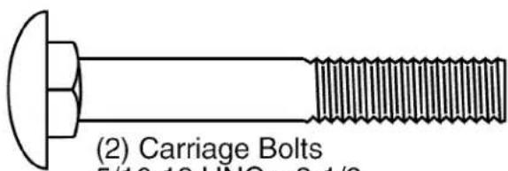
(2) Carriage Bolts 5/16-18 UNC x 2-1/2

(2) Flange Locknuts 5/16-18 UNC

(1) Bottle Engine Oil
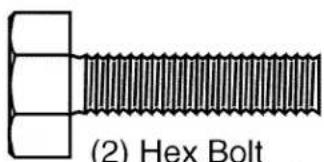
(2) Hex Bolt 5/16-18 x 1-1/4

(2) Lock Washer 5/16

(2) Hex Nut
5/16-18
Your new tiller has been assembled at the factory with the exception of those parts left unassembled for shipping purposes. To ensure safe and proper operation of your tiller all parts and hardware you assemble must be tightened securely. Use the correct tools as necessary to insure proper tightness.
TOOLS REQUIRED FOR ASSEMBLY
A socket wrench set will make assembly easier. Standard wrench sizes are listed.
(1) Utility knife
(2) 1/2 Wrench
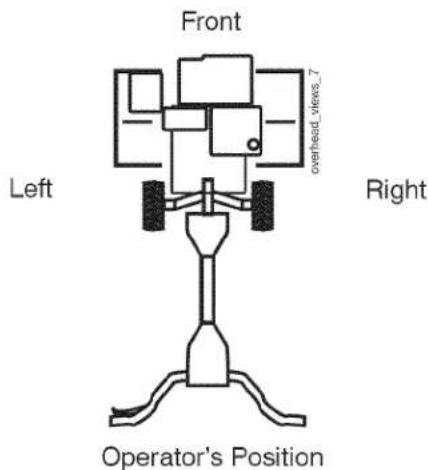
OPERATOR'S POSITION
When right or left hand is mentioned in this manual, it means when you are in the operating position (standing behind tiller handles).
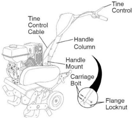
UNPACK CARTON & INSTALL HANDLE
CAUTION: Be careful of exposed staples when handling or disposing of cartoning material.
IMPORTANT: When unpacking and assembling tiller, be careful not to stretch or kink cable(s).
- Cut cable ties securing handle column.
- Route cable(s) as shown and slide handle column onto handle mount.
- Remove all packing from carton.
- Secure handle column using two (2) carriage bolts and two (2) flange lock-nuts. Tighten securely.
- Cut away carton.
- Route tine control cable(s) through plastic cable clip on handle mount.
NOTE: Cables must not touch the muffler.
- Cut cable ties securing tiller to skid. Remove tiller from skid by pulling backwards.
- Remove screws securing depth stake to skid and discard the screws.
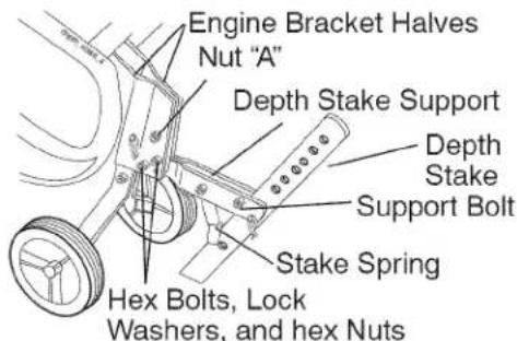
INSTALL DEPTH STAKE ASSEMBLY
- Loosen nut "A".
- Insert stake support between engine bracket halves with stake spring down.
- Bolt stake support to engine brackets with bolts, lock washers and nuts. Tighten securely. Tighten nut "A".
- Depth stake must move freely. If it does not, loosen support bolt.
HANDLE HEIGHT
- Handle height may be adjusted to better suit operator. (See "HANDLE HEIGHT" in the Service and Adjustments section of this manual).
TILLING WIDTH
- Tilling width may be adjusted to better handle your tilling conditions (See "TINE ARRANGEMENT" in the Service and Adjustments section of this manual).
TINE OPERATION
- Check time operation before first use. (See "TINE OPERATION CHECK" in the Service and Adjustments section of this manual).
OPERATION
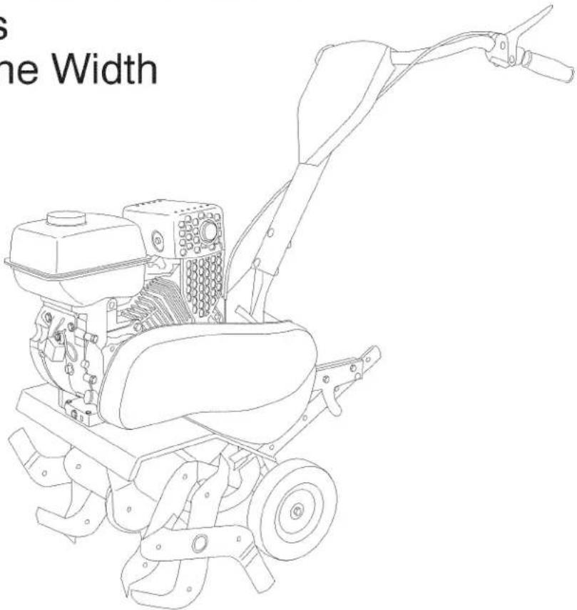
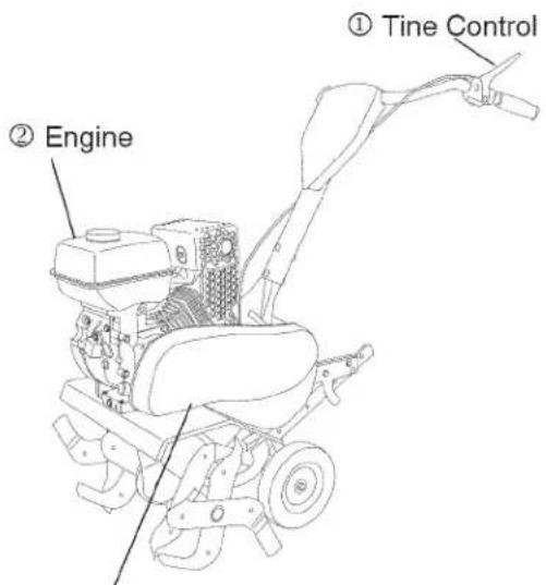
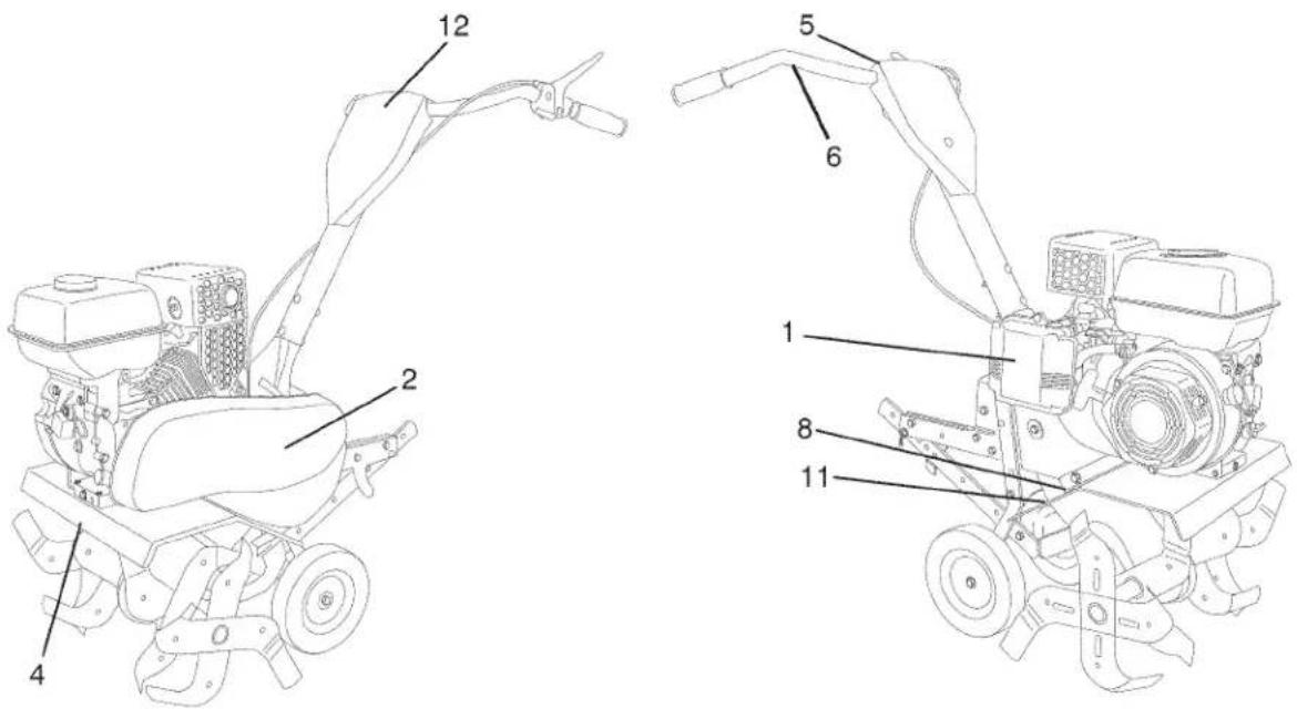
KNOW YOUR TILLER
READ THIS OWNER'S MANUAL AND SAFETY RULES BEFORE OPERATING YOUR TILLER
Compare the illustrations with your tiller to familiarize yourself with the locations of various controls and adjustments. Save this manual for future reference.
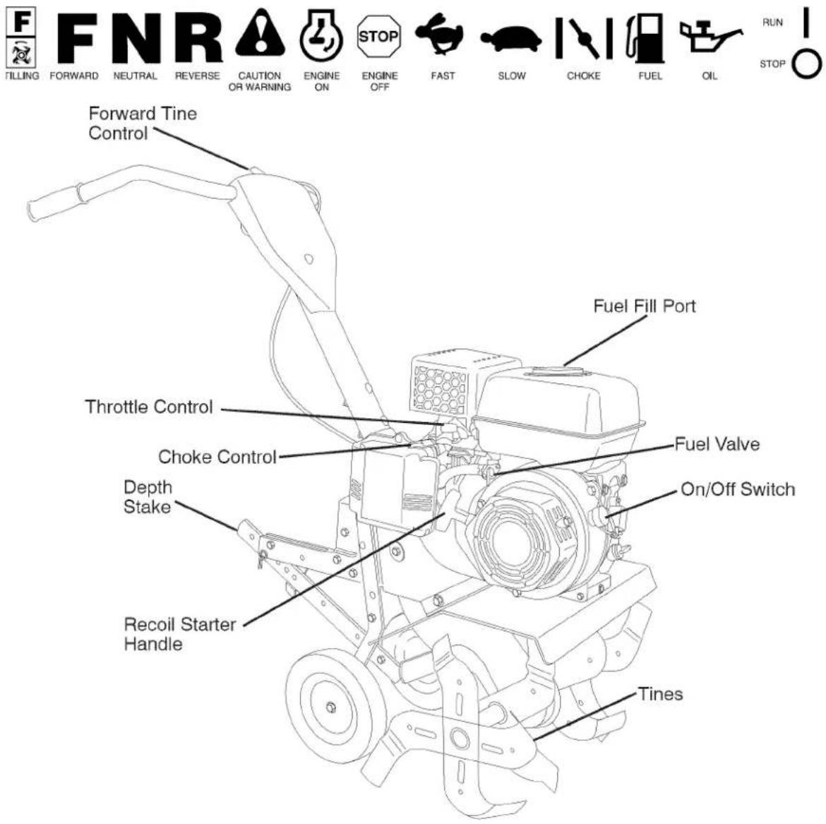
Our tillers conform to the safety standards of the American National Standards Institute.
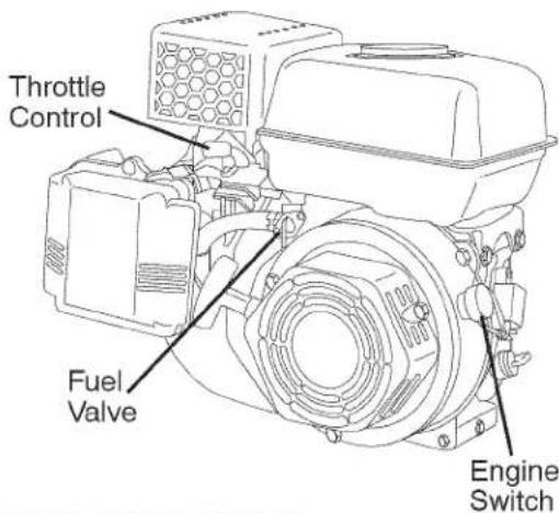
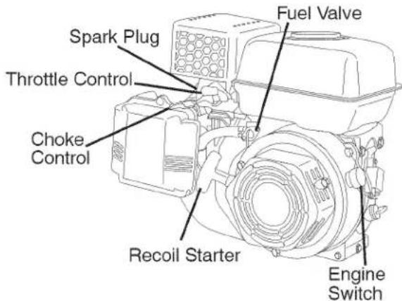
CHOKE CONTROL - Used when starting a cold engine.
DEPTH STAKE - Controls forward speed and the depth at which tiller will dig.
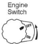
ENGINE ON/OFF SWITCH - The engine switch enables and disables the ignition system.
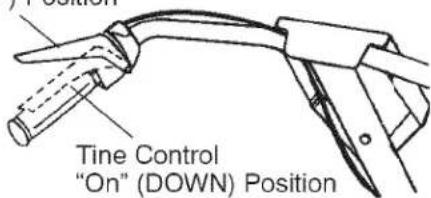
FORWARD TINE CONTROL - Engages tines in forward direction.
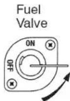
FUEL VALVE - The fuel valve opens and closes the passage between the fuel tank and the carburetor.
RECOIL STARTER HANDLE - Used to start the engine.
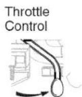
THROTTLE CONTROL - Used to control engine speed.

The operation of any tiller can result in foreign objects thrown into the eyes, which can result in severe eye damage. Always wear safety glasses or eye shields before starting your tiller and while tilling. We recommend standard safety glasses or a wide vision safety mask worn over spectacles.
HOW TO USE YOUR TILLER
Know how to operate all controls before adding fuel and oil or attempting to start engine.
STOPPING
TINES
- Release time control to stop movement. ENGINE
- Move throttle control to "SLOW" position and allow the engine to run slowly for cool down.
- Turn the engine switch to the "OFF" Position.
- Turn the fuel valve lever to the "OFF" Position.
NOTE: Never use choke to stop engine.
IMPORTANT: To stop engine in an emergency, turn the engine switch to the OFF position.
Tine Control "Off" (UP) Position
TINE OPERATION
- Squeeze tine control to handle.
TILLING
The speed and depth of tilling is regulated by the position of the depth stake and wheel height.
The depth stake should always be below the wheels for digging. It serves as a brake to slow the tiller's forward motion to enable the tines to penetrate the ground. Also, the more the depth stake is lowered into the ground the deeper the tines will dig.
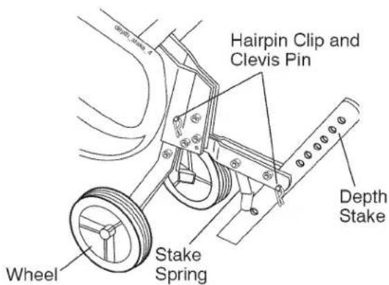
DEPTH STAKE
Adjust depth stake by removing the hairpin clip and clevis pin. Change depth stake to desired position. Replace the clevis pin and hairpin clip.
- For normal tilling, set depth stake at the second or third hole from the top.
WHEELS
Adjust wheels by removing the hairpin clip and clevis pin. Change wheel position.
Replace the hairpin clip and clevis pin.
- For normal tilling, set wheels at the second or third hole from the top.
TO TRANSPORT
ACAUTION: Before lifting or transporting, allow tiller engine and muffler to cool. Disconnect spark plug wire. Drain gasoline from fuel tank.
AROUND THE YARD
- Tip depth stake forward until it is held by the stake spring.
- Push tiller handles down, raising tines off the ground.
- Push or pull tiller to desired location.
AROUND TOWN
- Disconnect spark plug wire.
- Drain fuel tank.
- Transport in upright position to prevent oil leakage.
BEFORE STARTING ENGINE
IMPORTANT: Be very careful not to allow dirt to enter the engine when checking or adding oil or fuel. Use clean oil and fuel and store in approved, clean, covered containers. use clean fill funnels.
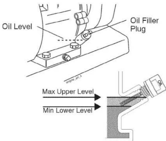
FILL ENGINE WITH OIL
- Remove hangtag from engine.
- With engine level, remove engine oil filler plug.
- Fill engine with oil to point of overflowing. For approximate capacity see "PRODUCT SPECIFICATIONS" on page 4 of this manual. All oil must meet A.P.I. Service Classification SG-SL.
- Tilt tiller back on its wheels and then re-level.
- With engine level, refill to point of overflowing if necessary. Replace oil filler plug.
- For cold weather operation you should change oil for easier starting (See "OIL VISCOSITY CHART" in the Maintenance section of this manual).
• To change engine oil, see the Maintenance section of this manual.
ADD GASOLINE
- Fill fuel tank to bottom of filler neck. Do not overfill. Use fresh, clean, regular unleaded gasoline with a minimum of 87 octane. (Use of leaded gasoline will increase carbon and lead oxide deposits and reduce valve life). Do not mix oil with gasoline. Purchase fuel in quantities that can be used within 30 days to assure fuel freshness.
CAUTION: Fill to within 1/2 inch of top of fuel tank to prevent spills and to allow for fuel expansion. If gasoline is accidentally spilled, move machine away from area of spill. Avoid creating any source of ignition until gasoline vapors have disappeared.
Wipe off any spilled oil or fuel. Do not store, spill or use gasoline near an open flame.
IMPORTANT: When operating in temperatures below 32irc F( 0irc C), use fresh, clean winter grade gasoline to help insure good cold weather starting.
CAUTION: Alcohol blended fuels (called gasohol or using ethanol or methanol) can attract moisture which leads to separation and formation of acids during storage. Acidic gas can damage the fuel system of an engine while in storage. To avoid engine problems, the fuel system should be emptied before storage of 30 days or longer. Drain the gas tank, start the engine and let it run until the fuel lines and carburetor are empty. Use fresh fuel next season. See Storage Instructions for additional information. Never use engine or carburetor cleaner products in the fuel tank or permanent damage may occur.
TO START ENGINE
CAUTION: Keep time control in "OFF" position when starting engine.
When starting engine for the first time or if engine has run out of fuel, it will take extra pulls of the recoil starter to move fuel from the tank to the engine.
- Make sure spark plug wire is properly connected.
- Place the fuel valve to the "ON" position.
- To start a cold engine, move the choke lever to the "ON" position.
- Move the throttle lever away from the "SLOW" position, about 1/3 of the way toward the "FAST" position.
- Turn the engine switch to the "ON" position. Pull rope out slowly until engine reaches start of compression cycle (rope will pull slightly harder at this point).
- Pull recoil starter handle quickly. Do not let starter handle snap back against starter. Repeat if necessary.
NOTE: If engine fires but does not start, move choke control to half choke position. Pull recoil starter handle until engine starts.
- If the choke lever has been moved to the "ON" position to start the engine, gradually move it to the opposite position as the engine warms up.
NOTE: A warm engine requires less choking to start.
-
Move throttle control to desired running position.
-
Allow engine to warm up for a few minutes before engaging tines.
NOTE: If engine does not start, see troubleshooting points.
Break-in your belt(s), pulleys and tine control before you actually begin tilling.
- Start engine, tip tines off ground by pressing handles down and engage tine control to start tine rotation. Allow tines to rotate for five minutes.
- Check time operation and adjust if necessary. See "TINE OPERATION CHECK" in the Service and Adjustments section of this manual.
TILLING HINTS
CAUTION: Until you are accustomed to handling your tiller, start actual field use with throttle in slow position.
To help tiller move forward, lift up the handles slightly (thus lifting depth stake out of ground). To slow down the tiller, press down on handles. If you are straining or tiller is shaking, the wheels and depth stake are not set properly in the soil being tilled. The proper setting of the wheels and depth stake is through trial and error and depends upon the soil condition. (The harder or wetter the ground, the slower the engine and time speed needed. Under these poor conditions, at fast speed the tiller will run and jump over the ground).
A properly adjusted tiller will dig with little effort from the operator.
- Tilling is digging into, turning over, and breaking up packed soil before planting. Loose, unpacked soil helps root growth. Best tilling depth is 4"-6". A tiller will also clear the soil of unwanted vegetation. The decomposition of this vegetable matter enriches the soil. Depending on the climate (rainfall and wind), it may be advisable to till the soil at the end of the growing season to further condition the soil.
- Soil conditions are important for proper tilling. Tines will not readily penetrate dry, hard soil which may contribute to excessive bounce and difficult handling of your tiller. Hard soil should be moistened before tilling; however, extremely wet soil will "ball-up" or clump during tilling. Wait until the soil is less wet in order to achieve the best results. When tilling in the fall, remove vines and long grass to prevent them from wrapping around the tine shaft and slowing your tilling operation.
- You will find tilling much easier if you leave a row untilled between passes. Then go back between tilled rows There are two reasons for doing this. First, wide turns are much easier to negotiate than about-faces. Second, the tiller won't be pulling itself, and you, toward the row next to it.
- Set depth stake and wheel height for shallow tilling when working extremely hard soil or sod. Then work across the first cuts at normal depth.

flowchart
graph TD
    A["4"] -->|5| B["3"]
    B -->|6| C["2"]
    C -->|7| D["1"]
    D -->|7| A
    A -->|7| C
    B -->|7| C
    C -->|7| D
    D -->|7| A
CULTIVATING
Cultivating is destroying the weeds between rows to prevent them from robbing nourishment and moisture from the plants. At the same time, breaking up the upper layer of soil crust will help retain moisture in the soil. Best digging depth is 1"-3".
- You will probably not need to use the depth stake. Begin by tipping the depth stake forward until it is held by the stake spring.
- Cultivate up and down the rows at a speed which will allow tines to uproot weeds and leave the ground in rough condition, promoting no further growth of weeds and grass.
natural_image
Diagram of three parallel U-shaped structures with hexagonal patterns inside, connected by a downward arrow (no text or symbols)MAINTENANCE
| MAINTENANCESCHEDULEFILL IN DATESAS YOU COMPLETEREGULAR SERVICE | BEFORE EACH USEEVERY 5 HOURSEVERY 25 HOURSEVERY 50 HOURS | SERVICE DATES | |||||||||||||
| Check Engine Oil Level | √ | √ | |||||||||||||
| Change Engine Oil | heckmark1,2 | ||||||||||||||
| Oil Pivot Points | √ | ||||||||||||||
| Inspect Spark Arrester / Muffler | √ | ||||||||||||||
| Inspect Air Screen | √ | ||||||||||||||
| Clean or Replace Air Cleaner Cartridge | heckmark2 | ||||||||||||||
| Clean Engine Cylinder Fins | √ | ||||||||||||||
| Replace Spark Plug | √ | ||||||||||||||
1 - Change more often when operating under a heavy load or in high ambient temperatures.
2 - Service more often when operating in dirty or dusty conditions.
GENERAL RECOMMENDATIONS
The warranty on this tiller does not cover items that have been subjected to operator abuse or negligence. To receive full value from the warranty, the operator must maintain tiller as instructed in this manual. Some adjustments will need to be made periodically to properly maintain your tiller. All adjustments in the Service and Adjustments section of this manual should be checked at least once each season.
- Once a year you should replace the spark plug, clean or replace air filter, and check tines and belts for wear. A new spark plug and clean air filter assure proper air-fuel mixture and help your engine run better and last longer.
BEFORE EACH USE
- Check engine oil level.
- Check tine operation.
- Check for loose fasteners.
LUBRICATION
Keep unit well lubricated (See "LUBRICATION CHART").
LUBRICATION CHART
① Idler Arm
① SAE 30 OR 10W-30 MOTOR OIL
② REFER TO MAINTENANCE "ENGINE" SECTION
⚠️CAUTION: Disconnect spark plug wire before performing any maintenance to prevent accidental starting of engine. Prevent fires! Keep the engine free of grass, leaves, spilled oil, or fuel. Remove fuel from tank before tipping unit for maintenance. Clean muffler area of all grass, dirt, and debris. Do not touch hot muffler or cylinder fins as contact may cause burns.
ENGINE
LUBRICATION
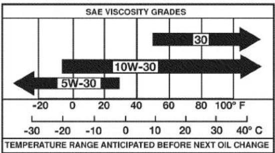
Use only high quality detergent oil rated with API service classification SG-SL. Select the oil's SAE viscosity grade according to your expected temperature.
bar
SAE VISCOSITY GRADES | Grade | Value | |---|---| | 30 | 80 | | 10W-30 | 60 | | 5W-30 | 20 | TEMPERATURE RANGE ANTICIPATED BEFORE NEXT OIL CHANGE Temperature Range ANTICIPATED BEFORE NEXT OIL CHANGENOTE: Although multi-viscosity oils (5W-30, 10W-30, etc.) improve starting in cold weather, these multi-viscosity oils will result in increased oil consumption when used above 32irc F ( 0irc C). Check your engine oil level more frequently to avoid possible engine damage from running low on oil. Change the oil after every 50 hours of operation or at least once a year if the tiller is not used for 50 hours in one year. Check the crankcase oil level before starting the engine and after each five (5) hours of continuous use. Add SAE 30 motor oil or equivalent. Tighten oil filler plug securely each time you check the oil level.
Determine temperature range expected before oil change. All oil must meet API service classification SG-SL.
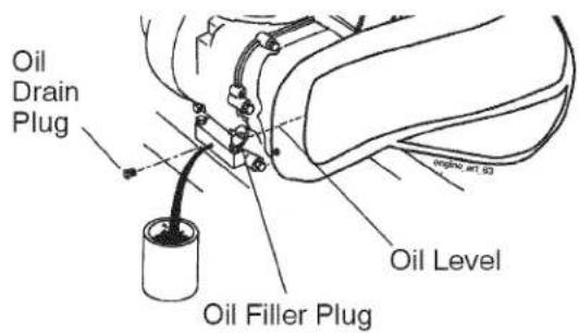
- Be sure tiller is on level surface.
• Oil will drain more freely when warm. -
Catch oil in a suitable container.
-
Remove drain plug.
- Tip tiller forward to drain oil.
- After oil has drained completely, replace oil drain plug and tighten securely.
-
Remove oil filler plug. Be careful not to allow dirt to enter the engine.
-
Refill engine with oil. See "FILL ENGINE WITH OIL" in the Operation section of this manual.
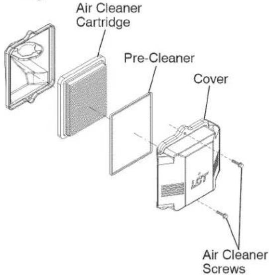
AIR CLEANER
Service air cleaner cartridge every twenty-five hours, more often if engine is used in very dusty conditions.
- Loosen air cleaner screw(s).
- Remove air cleaner cover.
- Carefully remove air cleaner cartridge. Be careful. Do not allow dirt or debris to fall into carburetor.
- Clean by tapping gently on a flat surface.
NOTE: If very dirty or damaged, replace cartridge.
- Clean and replace cover. Tighten screw(s) securely.
CAUTION: Petroleum solvents, such as kerosene, are not to be used to clean cartridge. They may cause deterioration of the cartridge. Do not oil cartridge. Do not use pressurized air to clean or dry cartridge.
COOLING SYSTEM
Your engine is air cooled. For proper engine performance and long life keep your engine clean.
- Clean air screen frequently using a stiff-bristled brush.
- Remove blower housing and clean as necessary.
- Keep cylinder fins free of dirt and chaff.
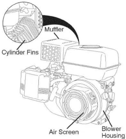
MUFFLER
Do not operate tiller without muffler. Do not tamper with exhaust system. Damaged mufflers or spark arresters could create a fire hazard. Inspect periodically and replace if necessary. If your engine is equipped with a spark arrester screen assembly, remove every 50 hours for cleaning and inspection. Replace if damaged.
SPARK PLUG
Replace spark plugs at the beginning of each tilling season or after every 25 hours of use, whichever comes first. Spark plug type and gap setting are shown in "PRODUCT SPECIFICATIONS" on page 4 of this manual.
TRANSMISSION
Your transmission is sealed and will not require lubrication unless serviced.
CLEANING
Do not clean your tiller when the engine and transmission are hot. We do not recommend using pressurized water (garden hose, etc.) to clean your unit unless the gasket area around the transmission and the engine muffler, air filter and carburetor are covered to keep water out. Water in engine will shorten the useful life of your tiller.
- Clean engine, wheels, finish, etc. of all foreign matter.
- Keep finished surfaces and wheels free of all gasoline, oil, etc.
- Protect painted surfaces with automotive type wax.
SERVICE AND ADJUSTMENTS
⚠️CAUTION: Disconnect spark plug wire from spark plug and place wire where it cannot come into contact with plug.
TILLER
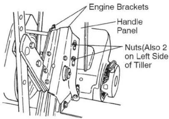
TO ADJUST HANDLE HEIGHT
Factory assembly has provided lowest handle height. Select handle height best suited for your tilling conditions. Handle height will be different when tiller digs into soil.
- If a higher handle height is desired, loosen the four nuts securing handle panel to engine brackets.
- Slide handle panel to desired location.
- Tighten the four nuts securely.
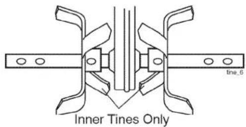
TINE ARRANGEMENT
Your outer tines can be assembled in several different ways to suit your tilling or cultivating needs.
CAUTION: Tines are sharp. Wear gloves or other protection when handling tines.
- Assemble holes "A" in tine hubs to holes "B" in tine shaft.
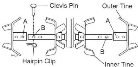
- Assemble holes "A" in tine hubs to holes "C" in tine shaft.
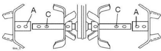
- Remove outer tines.
NOTE: When reassembling outer tines,
be sure right tine assembly (marked "R") and left tine assembly (marked "L") are mounted to correct side of tine shaft.
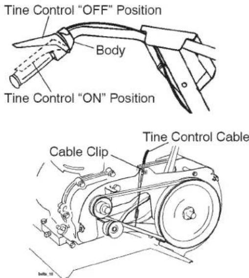
WARNING: Disconnect spark plug wire from spark plug to prevent starting while checking tine operation. For proper tine operation, tine control lever must be against control body and all slack removed from inner wire of control cable when control is in the "OFF" (up) position. If lever and cable are loose, loosen cable clip at lower end of cable. Pull up on cable to remove slack, without extending spring on end of cable, and retighten cable clip.
- With tine control "OFF" (up), push down on handle to raise tines off the ground.
- Slowly pull recoil starter handle while observing tines. Tines should not rotate.
- If tines rotate, inner wire of control cable is too tight which is extending lower spring and engaging tines. Loosen cable clip and push down on cable only enough to relieve spring tension. Tighten cable clip.
-
Recheck in "OFF" position and adjust if necessary.
-
With tine control "ON" (held down to handle) push down on handle to raise tines off the ground.
- Slowly pull recoil starter handle while observing tines. Tines should rotate forward.
- If tines do not rotate, inner wire of control cable is too loose. Loosen cable clip and pull cable up to remove slack and retighten clip.
- Recheck in "ON" position and adjust if necessary.
NOTE: If "ON" position check required adjustment, recheck "OFF" position adjustment to insure tines do not rotate when control is "OFF" (up).
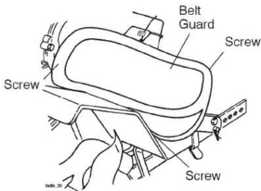
TO REMOVE BELT GUARD
- Remove screws from side of belt guard.
- Pull belt guard out and away from unit.
- Replace belt guard by reversing above procedure. Be sure slot in bottom of belt guard is under head of tine shield bolt and all nuts are tightened securely.
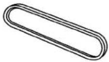
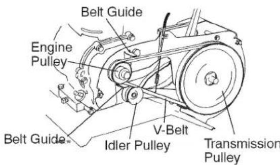
TO REPLACE V-BELT
Replace V-belt if it has stretched considerably or if it has cracks or frayed edges.
- Belt guard must be removed to service belt. See "TO REMOVE BELT GUARD" in this section of manual.LT REMOVAL
- Remove V-belt from transmission pulley first and then from engine pulley.
BELT REPLACEMENT
- Install new V-belt to engine pulley first then to transmission pulley. Be sure belt is positioned on inside groove of both pulleys, inside all belt guides and rests on idler pulley.
- See "TINE OPERATION CHECK" in this section of manual.
- Replace belt guard
ENGINE
Maintenance, repair, or replacement of the emission control devices and systems, which are being done at the customers expense, may be performed by any non-road engine repair establishment or individual.
Warranty repairs must be performed by an authorized engine manufacturer's service outlet.
IMPORTANT: Never tamper with the engine governor, which is factory set for proper engine speed. Overspeeding the engine above the factory high speed setting can be dangerous. If you think the engine-governed high speed needs adjusting, contact your nearest sears or other qualified service center which has the proper equipment and experience to make any necessary adjustments.
STORAGE
Immediately prepare your tiller for storage at the end of the season or if the unit will not be used for 30 days or more.
Warning: Never store the tiller with gasoline in the tank inside a building where fumes may reach an open flame or spark. Allow the engine to cool before storing in any enclosure.
TILLER
- Clean entire tiller (See "CLEANING" in the Maintenance section of this manual).
- Inspect and replace belts, if necessary (See belt replacement instructions in the Service and Adjustments section of this manual).
- Lubricate as shown in the Maintenance section of this manual.
- Be sure that all nuts, bolts and screws are securely fastened. Inspect moving parts for damage, breakage and wear. Replace if necessary.
- Touch up all rusted or chipped paint surfaces; sand lightly before painting.
ENGINE
FUEL SYSTEM
IMPORTANT: It is important to prevent gum deposits from forming in essential fuel system parts such as the carburetor, fuel filter, fuel hose, or tank during storage. Also, alcohol blended fuels (called gasohol or using ethanol or methanol) can attract moisture which leads to separation and formation of acids during storage. Acidic gas can damage the fuel system of an engine while in storage.
- Empty the fuel tank by starting the engine and letting it run until the fuel lines and carburetor are empty.
- Never use engine or carburetor cleaner products in the fuel tank or permanent damage may occur.
• Use fresh fuel next season.
NOTE: Fuel stabilizer is an acceptable alternative in minimizing the formation of fuel gum deposits during storage. Add stabilizer to gasoline in fuel tank or storage container. Always follow the mix ratio found on stabilizer container. Run engine at least 10 minutes after adding stabilizer to allow the stabilizer to reach the carburetor. Do not empty the gas tank and carburetor if using fuel stabilizer.
ENGINE OIL
Drain oil (with engine warm) and replace with clean oil. (See "ENGINE" in the Maintenance section of this manual).
CYLINDER
- Remove spark plug.
- Pour 1 ounce (29 ml) of oil through spark plug hole into cylinder.
- Pull starter handle slowly several times to distribute oil.
- Replace with new spark plug.
OTHER
- Do not store gasoline from one season to another.
- Replace your gasoline can if your can starts to rust. Rust and/or dirt in your gasoline will cause problems.
- If possible, store your unit indoors and cover it to give protection from dust and dirt.
- Cover your unit with a suitable protective cover that does not retain moisture. Do not use plastic. Plastic cannot breathe which allows condensation to form and will cause your unit to rust.
IMPORTANT: Never cover tiller while engine and exhaust areas are still warm.
TROUBLESHOOTING CHART:
See appropriate section in manual unless directed to Sears service center
| PROBLEM | CAUSE | CORRECTION | ||
| Will not start | 1 | Out of fuel. | 1 | Fill fuel tank. |
| 2 | Fuel valve "OFF" | 2 | Turn fuel valve to the "ON" position. | |
| 3 | Engine Switch "OFF" | 3 | Turn engine switch to the "ON" position. | |
| 4 | Engine not "CHOKED" properly. | 4 | See "TO START ENGINE" in Operation section. | |
| 5 | Engine flooded. | 5 | Wait several minutes before attempting to start. | |
| 6 | Bad spark plug or improper gap. | 6 | Replace spark plug or adjust gap. | |
| 7 | Dirty air filter. | 7 | Clean/replace air filter. | |
| 8 | Water in fuel. | 8 | Empty fuel tank and carburetor, refill tank with fresh gasoline. | |
| Hard to start | 1 | Throttle control not set properly. | 1 | See "To Start Engine" in Operations section. |
| 2 | Dirty air filter. | 2 | Clean/replace air filter. | |
| 3 | Bad spark plug or improper gap. | 3 | Replace spark plug or adjust gap. | |
| 4 | Stale or dirty fuel. | 4 | Empty fuel tank and refill tank with fresh, clean gasoline. | |
| 5 | Loose spark plug wire. | 5 | Make sure spark plug wire is seated properly. | |
| Loss of power | 1 | Engine is overloaded | 1 | Set depth stake and wheels for shallower tilling. |
| 2 | Dirty air cleaner | 2 | Clean/replace air filter. | |
| 3 | Low oil level/dirty oil. | 3 | Check oil level/change oil. | |
| 4 | Faulty spark plug. | 4 | Clean and regap or change spark plug. | |
| 5 | Oil in fuel | 5 | Empty and clean fuel tank and refill, and clean carburetor. | |
| 6 | Stale or dirty fuel. | 6 | Empty fuel tank and refill tank with fresh, clean gasoline. | |
| 7 | Water in fuel. | 7 | Empty fuel tank and carburetor, refill tank with fresh gasoline. | |
| 8 | Clogged fuel tank. | 8 | Remove fuel tank and clean. | |
| 9 | Spark plug wire loose. | 9 | Connect and tighten spark plug wire. | |
| 10 | Dirty engine air screen. | 10 | Clean engine air screen. | |
| 11 | Dirty/clogged muffler. | 11 | Clean/replace muffler. | |
| 12 | Poor Compression | 12 | Contact a Sears or other qualified service center. | |
| Engine overheats | 1 | Low oil level/dirty oil. | 1 | Check oil level/change oil. |
| 2 | Dirty engine air screen. | 2 | Clean engine air screen. | |
| 3 | Dirty engine. | 3 | Clean cylinder fins, airscreen, muffler area | |
| 4 | Partially plugged muffler | 4 | Remove and clean muffler. |
TROUBLESHOOTING CHART:
See appropriate section in manual unless directed to Sears service center
| PROBLEM | CAUSE | CORRECTION | ||
| Excessive bounce/difficult handling | 1 | Ground too dry and hard. | 1 | Moisten ground or wait for more favorable soil conditions |
| 2 | Wheels and depth stake incorrectly adjusted. | 2 | Adjust wheels and depth stake. | |
| Soil balls up or clumps | 1 | Ground too wet. | 1 | Wait for more favorable conditions. |
| Engine runs but tiller won't move | 1 | Tine control is not engaged. | 1 | Engage tine control |
| 2 | V-belt not correctly adjusted. | 2 | Inspect/adjust V-belt. | |
| 3 | V-belt is off pulley (s). | 3 | Inspect V-belt. | |
| Engine runs but labors when tilling | 1 | Tilling too deep. | 1 | Set depth stake for shallower tilling |
| 2 | Throttle control not properly adjusted. | 2 | Check throttle control setting. |
NEED MORE HELP?
You'll find the answer and more on managemyhome.com - for free!
- Find this and all your other product manuals online.
- Get answers from our team of home experts.
- Get a personalized maintenance plan for your home.
- Find information and tools to help with home projects.
manage my home
brought to you by Sears
TABLA DE CONTENIDOS
Garantía....20
natural_image
Diagram of three U-shaped pipes with scattered cloud-like shapes inside, no text or symbols presentMANTENIMENTO
You'll find the answer and more on managemyhome.com - for free!
• Find this and all your other product manuals online.
- Get answers from our team of home experts.
- Get a personalized maintenance plan for your home.
- Find information and tools to help with home projects.
manage my home
brought to you by Sears
REPAIR PARTS
TILLER -- MODEL NUMBER 917.299011
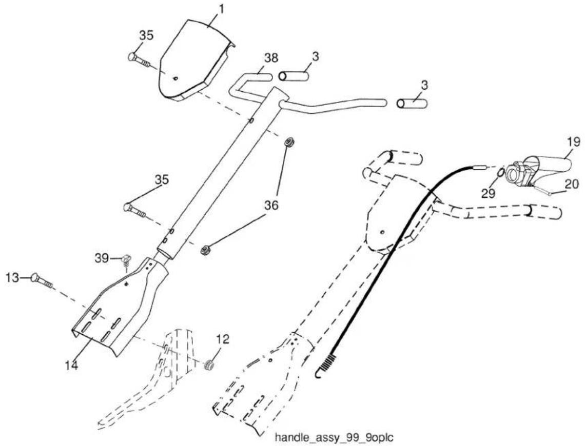
HANDLES
KEY PART
NO. NO.
| 1 | 137118 | Panel, Control |
| 3 | 165787 | Grip, Handle |
| 12 | 98000129 | Nut, Flange |
| 13 | STD533107 | Bolt, Carriage 5/16-18 x 3/4 |
| 14 | 181476 | Assembly, Panel and Tube |
| 19 | 188532 | Lever, Control, Tine |
| 20 | 188555 | Pin, Pivot |
| 29 | 12000059 | Retainer, Ring |
DESCRIPTION
KEY PART
NO. NO.
DESCRIPTION
| 35 | 72010520 | Bolt 5/16-18 x 2-1/2 |
| 36 | 73970500 | Locknut, Flange 5/16-18 unc |
| 38 | 417465 | Assembly, Handle Column |
| 39 | 181580 | Clip |
NOTE: All component dimensions given in U.S.inches. 1 inch = 25.4 mm
TILLER - - MODEL NUMBER 917.299011
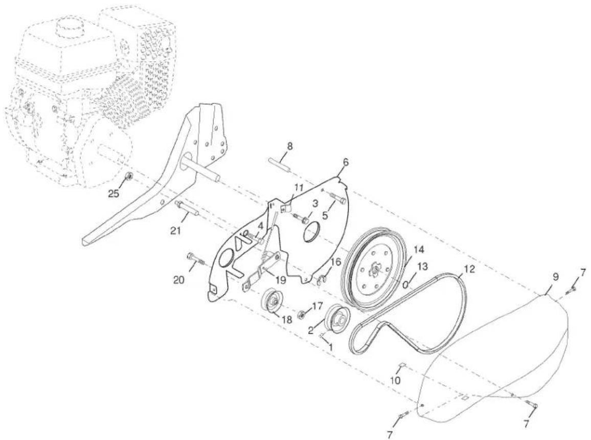
BELT GUARD AND PULLEY ASSEMBLY
belt_guard_LCT_1
KEY PART
NO. NO.
| 1 | 23230506 | Screw Set 5/16-18 x 3/8 Patch |
| 2 | 130812 | Sheave, Engine |
| 3 | 86777 | Screw, Tap Hex Head |
| 4 | 74770508 | Bolt, Hex Head 5/16-24 unf x 1/2 |
| 5 | 17490440 | Bolt, Thd Roller 1/4-20 x 2-1/2 |
| 6 | 422920 | Shield, Inner Belt Guard |
| 7 | 170488 | Screw Hex Wsh Hd #8-18 x 1/2 |
| 8 | 139155 | Spacer Split |
| 9 | 165768X615 | Guard, Belt |
| 10 | 109227X | Pad, Idler |
| 11 | 9484R | Clip, Cable |
| 12 | 9180R | V-Belt |
DESCRIPTION
KEY PART
NO. NO.
DESCRIPTION
| 13 | 12000028 | Ring, Retainer |
| 14 | 151223 | Sheave, Transmisison |
| 16 | 12000036 | Ring, Klip |
| 17 | STD541237 | Nut, Hex, Jam 3/8-16 |
| 18 | 161806 | Pulley, Idler |
| 19 | 175377 | Arm, Idler |
| 20 | STD523712 | Bolt, Hex Head 3/8-16 x 1-1/4 |
| 21 | 106968X | Shaft, Idler Arm |
| 25 | 73350500 | Nut, Hex, Jam 5/16-18 |
NOTE: All component dimensions given in U.S.inches. 1 inch = 25.4 mm
TILLER -- MODEL NUMBER 917.299011 WHEEL AND DEPTH STAKE ASSEMBLY
KEY PART NO. NO.
| 1 | 9194R | Pin, Clevis |
| 2 | 74760520 | Bolt, Hex Head 5/16-18 x 1-1/4 |
| 3 | STD523107 | Bolt, Hex Head 5/16-18 x 3/4 |
| 4 | 73220500 | Nut |
| 5 | STD551131 | Washer, Lock 5/16 |
| 6 | STD541437 | Locknut, w/washer 3/8-16 |
| 7 | 4921H | Clip, Hairpin |
| 8 | 1952J | Support, Depth Stake, R.H. |
| 9 | 122233X | Stake, Depth |
| 10 | 326J | Pin, Clevis |
| 11 | 74780628 | Bolt, Hex 3/8-16 x 1-3/4 |
| 13 | 1951J | Support, Depth Stake, L.H. |
| 15 | 5388J | Spring, Stake |
KEY PART NO. NO.
| 16 | 121117X | Bolt, Shoulder |
| 17 | 193851X613 | Wheel |
| 19 | 9190R | Bracket, Wheel |
| 20 | STD541437 | Locknut, Crown 3/8-16 |
| 21 | 74760516 | Bolt, Hex Head 5/16-18 x 1 |
| 22 | STD541431 | Locknut, w/insert 5/16-18 |
| 24 | 73970500 | Nut Lock 5/16-18 |
| 25 | 19171416 | Washer 17/32 x 7/8 x16 Ga. |
NOTE: All component dimensions given in U.S.inches. 1 inch = 25.4 mm
TILLER -- MODEL NUMBER 917.299011
TINE ASSEMBLY
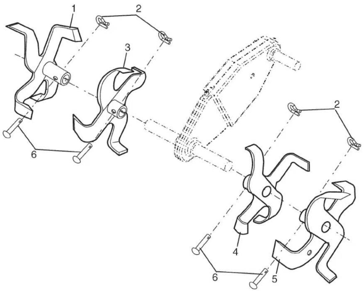
tine_ipb_3
KEY PART
NO. NO.
1 156926
2 3146R
3 156924
4 156923
DESCRIPTION
Tine, Outer, R.H.
Retainer, Spring Zinc
Tine, Inner, R.H.
Tine, Inner, L.H.
KEY PART
NO. NO.
5 156925
6 4929H
DESCRIPTION
Tine, Outer, L.H.
Pin, Clevis
NOTE: All component dimensions given in U.S.inches. 1 inch = 25.4 mm
TILLER -- MODEL NUMBER 917.299011
TRANSMISSION
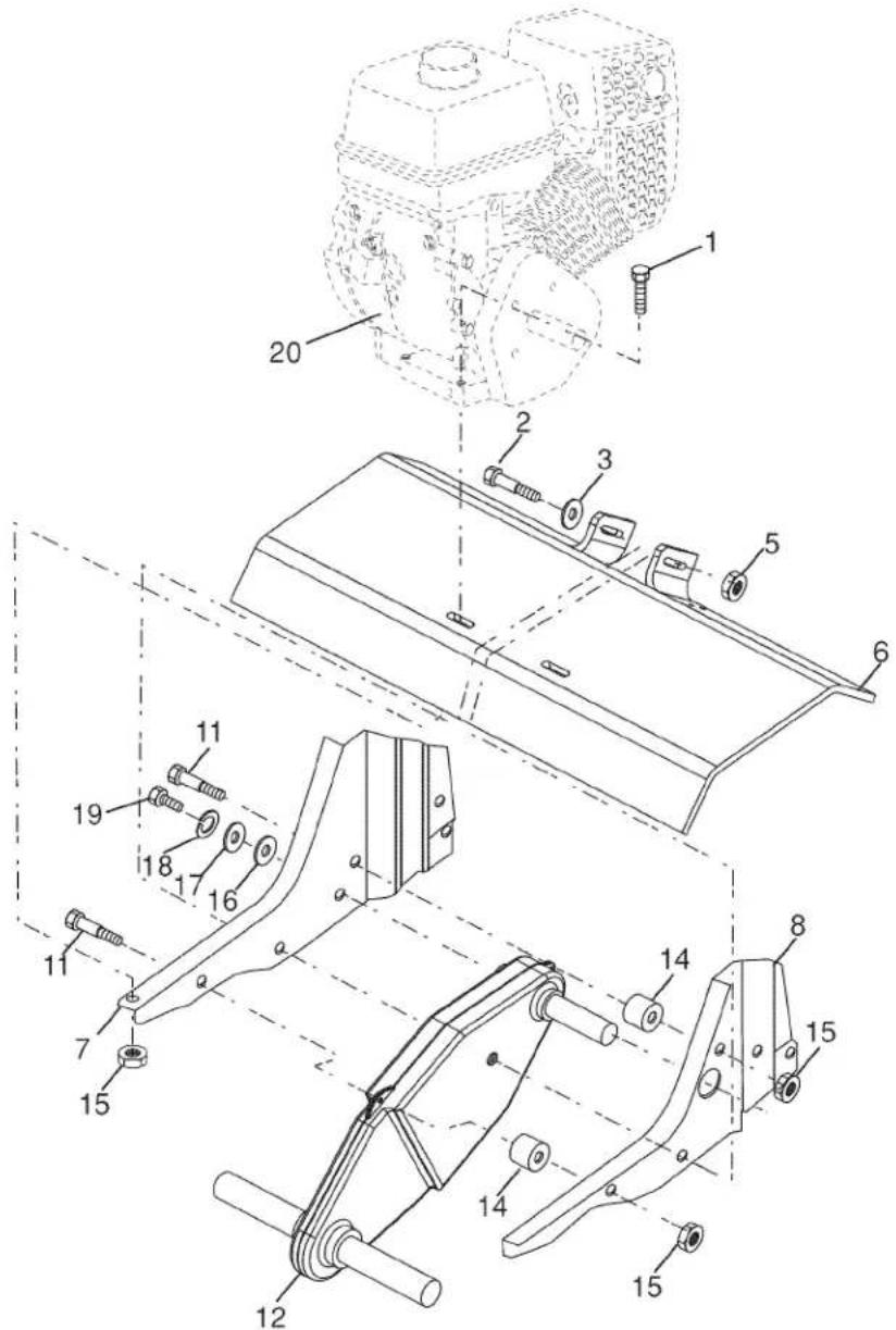
transmission_LCT_1
KEY PART
NO. NO.
| 1 | 74760524 | Bolt, Hex 5/16-18 x 1-1/2 Gr. 2 |
| 2 | STD523732 | Bolt, Fin, Hex 3/8-16 x 3-1/4 |
| 3 | STD551037 | Washer 13/32 x 13/16 x 11 |
| 5 | STD541437 | Locknut, w/washer 3/8-16 |
| 6 | 9056R615 | Shield, Tine |
| 7 | 188195 | Bracket, Engine, R.H. |
| 8 | 165834 | Bracket, Engine, L.H. |
| 11 | 187912 | Bolt, Shoulder 5/16-18 unc x 2.5 |
| 12 | 151222 | Transmission |
| 14 | 9173R | Spacer, Split |
KEY PART
NO. NO.
| 15 | 73970500 | Nut, Lock Hex Flange 5/16-18 unc |
| 16 | 19091412 | Washer 9/32 × 7/8 × 12 Ga. |
| 17 | 19092016 | Washer 9/32 × 1-1/4 × 16 Ga. |
| 18 | STD551125 | Washer, Lock 1/4 |
| 19 | 74610412 | Bolt, Hex 1/4-28 × 3/4 Gr. 5 |
| 20 | ---- | Engine (See Breakdown)LCT PLMHK14600124P-BPQE2 |
NOTE: All component dimensions given in U.S.inches. 1 inch = 25.4 mm
TILLER - - MODEL NUMBER 917.299011
DECALS
KEY PART
NO. NO.
1 423884
2 425502
4 425503
5 137539
6 120431X
8 162215
11 120075X
12 425501
-- 425340
DESCRIPTION
Decal, LCT900
Decal, Beltguard
Decal, Tine Shield
Decal, Cntrl Pnl Inst.
Decal, Hand Placement
Decal, Tine, Shield, Warning
Decal, Warning, Rotating Tines
Decal, Console
Manual, Owner's (Eng/Span)
TILLER -- MODEL NUMBER 917.299011 ENGINE, LCT -- MODEL NUMBER PLMHK14600124P-BPQE2
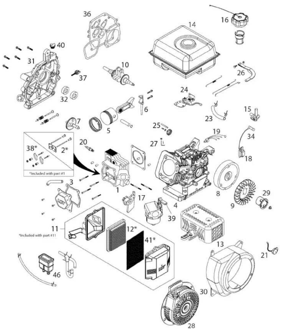
TILLER -- MODEL NUMBER 917.299011 ENGINE, LCT -- MODEL NUMBER PLMHK14600124P-BPQE2
KEY PART NO. NO.
| 1 | 420578 | Cylinder Head Service Kit Sk208-1000 |
| 2 | 420579 | Push Rod Service Kit Sk208-1001 |
| 3 | 420580 | Valve Cover Service Kit Sk4500 |
| 4 | 437294 | Cylinder Service Kit Sk208-1301 |
| 5 | 420582 | Piston Service Kit Sk208-1400 |
| 6 | 420583 | Connecting Rod Service Kit Sk208-1500 |
| 7 | 420584 | Camshaft Service Kit Sk208-1600 |
| 8 | 420585 | Flywheel Service Kit Sk208-1700 |
| 9 | 420586 | Cooling Fan Service Kit Sk208-4000 |
| 10 | 420587 | Crankshaft Service Kit Sk208-1800 |
| 11 | 420588 | Air Filter Assembly Service Kit Sk208-2002 |
| 12 | 437285 | Paper Filter Service Kit Sk208-2012 |
| 13 | 437287 | 49 State Fuel Muffler Service Kit Sk208-2101 |
| 14 | 420591 | 49 State Fuel Tank Service Kit Sk208-2200 |
| 15 | 437289 | Fuel Tank Petcock Service Kit Sk208-2221 |
| 16 | 420593 | 49 State Fuel Tank Cap Service Kit Sk208-2300 |
| 17 | 437290 | Carburetor Service Kit Sk208-2401 |
| 18 | 420595 | Ignition Coil Service Kit Sk208-2500 |
| 19 | 420596 | Ignition Module Service Kit Sk208-2750 |
| 20 | 437291 | Spark Plug Service Kit Sk208-3810 |
| 21 | 420598 | Engine On/off Switch Service Kit Sk208-2600 |
| 23 | 420638 | 1/4" fuel hose kit Sk208-6000 |
| 24 | 420599 | Throttle Control Service Kit Sk208-2800 |
| 25 | 420600 | Governor Gear Service Kit Sk208-2900 |
| 26 | 420601 | Governor Arm Service Kit Sk208-3000 |
| 27 | 420602 | Governor Crank Service Kit Sk208-3100 |
| 28 | 420603 | Recoil Starter Service Kit Sk208-3200 |
| 29 | 420604 | Starter Cup Service Kit Sk208-3300 |
| 30 | 420605 | Blower Housing Service Kit Sk208-3400 |
| 31 | 437292 | Pto Cover Service Kit Sk208-3601 |
| 32 | 420607 | Seal Service Kit Sk208-3900 |
| 34 | 420608 | Spark Plug Boot Service Kit Sk208-3800 |
| 36 | 436902 | Gasket Kit Sk208-4300 |
| 37 | 436906 | Small Black Dipstick Sk208-3711 |
| 38 | 436907 | Rocker Arm Assembly Sk208-1100 |
| 39 | 436908 | Choke Lever, Carburetor Sk208-2120 |
| 40 | 436909 | Non-Removable Oil Plug Sk208-3705 |
| 41 | 436910 | Foam Pre-Filter Sk208-9001 |
| 42 | 437293 | Oil Drain Plug Kit Sk208-9911 |
| -- | 420614 | Engine Replacement Service Kit |
NOTES/NOTAS
NOTES/NOTAS
NEED MORE HELP?
You'll find the answer and more on managemyhome.com - for free!
• Find this and all your other product manuals online.
- Get answers from our team of home experts.
- Get a personalized maintenance plan for your home.
• Find information and tools to help with home projects.
manage my home
brought to you by Sears
Get it fixed, at your home or ours!
Your Home
For repair – in your home – of all major brand appliances, lawn and garden equipment, or heating and cooling systems, no matter who made it, no matter who sold it!
For the replacement parts, accessories and owner's manuals that you need to do-it-yourself.
For Sears professional installation of home appliances and items like garage door openers and water heaters.
1-800-4-MY-HOME®
(1-800-469-4663)
www.sears.com
Anytime, day or night
(U.S.A. and Canada)
www.sears.ca
Our Home
For repair of carry-in products like vacuums, lawn equipment, and electronics, call or go on-line for the nearest Sears Parts and Repair Center.
1-800-488-1222 Anytime, day or night (U.S.A. only)
www.sears.com
To purchase a protection agreement (U.S.A.)
or maintenance agreement (Canada) on a product serviced by Sears:
1-800-827-6655 (U.S.A.)
1-800-361-6665 (Canada)
® Registered Trademark / ™ Trademark / ™ Service Mark of Sears Brands, LLC
- IMPORTANT:
- TABLE OF CONTENTS
- WARRANTY
- LIMITED ONE YEAR WARRANTY ON CRAFTSMAN TILLER
- SAFETY RULES
- TRAINING
- PREPARATION
- OPERATION
- MAINTENANCE AND STORAGE
- CUSTOMER RESPONSIBILITIES
- REPAIR PROTECTION AGREEMENTS
- SEARS INSTALLATION SERVICE
- ACCESSORIES
- UNASSEMBLED PARTS
- CONTENTS OF HARDWARE PACK
- TOOLS REQUIRED FOR ASSEMBLY
- OPERATOR'S POSITION
- UNPACK CARTON & INSTALL HANDLE
- INSTALL DEPTH STAKE ASSEMBLY
- HANDLE HEIGHT
- TILLING WIDTH
- TINE OPERATION
- KNOW YOUR TILLER
- READ THIS OWNER'S MANUAL AND SAFETY RULES BEFORE OPERATING YOUR TILLER
- HOW TO USE YOUR TILLER
- STOPPING
- TINES
- TILLING
- DEPTH STAKE
- WHEELS
- TO TRANSPORT
- AROUND THE YARD
- AROUND TOWN
- BEFORE STARTING ENGINE
- FILL ENGINE WITH OIL
- ADD GASOLINE
- TO START ENGINE
- TILLING HINTS
- CULTIVATING
- MAINTENANCE
- GENERAL RECOMMENDATIONS
- BEFORE EACH USE
- LUBRICATION
- ENGINE
- AIR CLEANER
- COOLING SYSTEM
- MUFFLER
- SPARK PLUG
- TRANSMISSION
- CLEANING
- SERVICE AND ADJUSTMENTS
- TILLER
- TO ADJUST HANDLE HEIGHT
- TINE ARRANGEMENT
- TO REMOVE BELT GUARD
- TO REPLACE V-BELT
- STORAGE
- FUEL SYSTEM
- ENGINE OIL
- CYLINDER
- OTHER
- TROUBLESHOOTING CHART:
- See appropriate section in manual unless directed to Sears service center
- NEED MORE HELP?
- TABLA DE CONTENIDOS
- MANTENIMENTO
- REPAIR PARTS
- TILLER -- MODEL NUMBER 917.299011
- HANDLES
- TILLER - - MODEL NUMBER 917.299011
- BELT GUARD AND PULLEY ASSEMBLY
- TILLER -- MODEL NUMBER 917.299011 WHEEL AND DEPTH STAKE ASSEMBLY
- TINE ASSEMBLY
- KEY PART
- NO.
- DESCRIPTION
- TILLER -- MODEL NUMBER 917.299011 ENGINE, LCT -- MODEL NUMBER PLMHK14600124P-BPQE2
- NOTES/NOTAS
- Get it fixed, at your home or ours!
- Your Home
- Our Home
Brand : Craftsman
Model : 917.299011
Category : Saw