917.275685 - Saw Craftsman - Free user manual and instructions
Find the device manual for free 917.275685 Craftsman in PDF.

User questions about 917.275685 Craftsman
0 question about this device. Answer the ones you know or ask your own.
Ask a new question about this device
Download the instructions for your Saw in PDF format for free! Find your manual 917.275685 - Craftsman and take your electronic device back in hand. On this page are published all the documents necessary for the use of your device. 917.275685 by Craftsman.
USER MANUAL 917.275685 Craftsman
Automatic Transmission
Model No.
917.275685
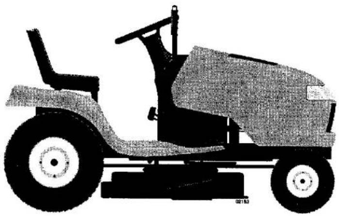
natural_image
Side profile illustration of a vintage off-road vehicle with large wheels and a handle (no text or symbols)
This product has a low emission engine which operates differently from previously built engines. Before you start the engine, read and understand this Owner's Manual.
IMPORTANT:
Read and follow all Safety Rules and Instructions before operating this equipment.
For answers to your questions about this product, Call:
1-800-659-5917
Sears Craftsman Help Line 5 am - 5 pm, Mon - Sat
Sears, Roebuck and Co., Hoffman Estates, IL 60179 U.S.A
Visit our Craftsman website:www.sears.com/craftsman
TABLE OF CONTENTS
Warranty 2
Safety Rules 3
Product Specifications....6
AssemblyPre-Operation 7
Operation....10
Maintenance 17
Maintenance Schedule....17
Service and Adjustments....22
Storage 29
Troubleshooting 30
Repair Parts.... 34
Sears Service......Back Cover
WARRANTY
LIMITED WARRANTY ON CRAFTSMAN RIDING EQUIPMENT
For two (2) years from the date of purchase, if this Craftsman Riding Equipment is maintained, lubricated and tuned up according to the instructions in the owner's manual, Sears will repair or replace free of charge any parts that are found to be defective in material or workmanship according to the guidelines of coverage listed below. Sears will also provide free labor for these applicable warranted parts for the two full years. During the first 30 days of purchase, there will be no charges to service the product at your home for issues covered by this warranty. (See exclusions below). For your convenience, IN HOME warranty service will still be available after the first 30 days of purchase, but a trip charge will apply. This charge will be waived if the Craftsman product is dropped off at an authorized Sears location. For the nearest authorized Sears location, please call 1-800-4-MY-HOME®. This warranty applies only while this product is within the United States.
This Warranty does not cover:
- Expendable items which become worn during normal use, including but not limited to blades, spark plugs, air cleaners, belts, and oil filters.
• Standard Maintenance Servicing, oil changes, or tune-ups - Tire replacement or repair caused by punctures from outside objects, such as nails, thorns, stumps, or glass.
- Repairs necessary because of operator abuse, including but not limited to, damage caused by towing objects beyond the capability of the riding equipment, impacting objects that bend the frame or crankshaft, or over-speeding the engine.
- Repairs necessary because of operator negligence, including but not limited to, electrical and mechanical damage caused by improper storage, failure to use the proper grade and amount of engine oil, failure to keep the deck clear of flammable debris, or failure to maintain the equipment according to the instructions contained in the owner's manual.
- Engine (fuel system) cleaning or repairs caused by fuel determined to be contaminated or oxidized (stale). In general, fuel should be used within 30 days of its purchase date.
- Normal deterioration and wear of the exterior finishes, or product label replacement.
- Riding equipment used for commercial or rental purposes.
LIMITED WARRANTY ON BATTERY
For ninety (90) days from date of purchase, if any battery included with this riding equipment proves defective in material or workmanship and our testing determines the battery will not hold a charge, Sears will replace the battery at no charge. During the first 30 days of purchase, there will be no charges to replace the battery at your HOME. After the first 30 days, for your convenience, IN-HOME warranty service will still be available but a trip charge will apply. This charge will be waived if the Craftsman product is dropped off at an authorized Sears location. For the nearest authorized Sears location, please call 1-800-4-MY-HOME®.
This battery warranty applies only while this product is within the United States.
This warranty gives you specific legal rights, and you may also have other rights, which vary, from state to state.
Sears, Roebuck and Co., Dept. 817WA, Hoffman Estates, IL 60179
SAFETY RULES
IMPORTANT: This cutting machine is capable of amputating hands and feet and throwing objects. Failure to observe the following safety instructions could result in serious injury or death.
WARNING: In order to prevent accidental starting when setting up, transporting, adjusting or making repairs, always disconnect spark plug wire and place wire where it cannot contact spark plug.
WARNING: Do not coast down a hill in neutral, you may lose control of the tractor.
WARNING: Tow only the attachments that are recommended by and comply with specifications of the manufacturer of your tractor. Use common sense when towing. Operate only at the lowest possible speed when on a slope. Too heavy of a load, while on a slope, is dangerous. Tires can lose traction with the ground and cause you to lose control of your tractor.
WARNING: Engine exhaust, some of its constituents, and certain vehicle components contain or emit chemicals known to the State of California to cause cancer and birth defects or other reproductive harm.
WARNING: Battery posts, terminals and related accessories contain lead and lead compounds, chemicals known to the State of California to cause cancer and birth defects or other reproductive harm. Wash hands after handling.
I. GENERAL OPERATION
- Read, understand, and follow all instructions on the machine and in the manual before starting.
- Do not put hands or feet near rotating parts or under the machine. Keep clear of the discharge opening at all times.
- Only allow responsible adults, who are familiar with the instructions, to operate the machine.
- Clear the area of objects such as rocks, toys, wire, etc., which could be picked up and thrown by the blades.
- Be sure the area is clear of bystanders before operating. Stop machine if anyone enters the area.
• Never carry passengers. -
Do not mow in reverse unless absolutely necessary. Always look down and behind before and while backing.
-
Never direct discharged material toward anyone. Avoid discharging material against a wall or obstruction. Material may ricochet back toward the operator. Stop the blades when crossing gravel surfaces.
- Do not operate machine without the entire grass catcher, discharge guard, or other safety devices in place and working.
- Slow down before turning.
- Never leave a running machine unattended. Always turn off blades, set parking brake, stop engine, and remove keys before dismounting.
- Disengage blades when not mowing. Shut off engine and wait for all parts to come to a complete stop before cleaning the machine, removing the grass catcher, or unclogging the discharge guard.
- Operate machine only in daylight or good artificial light.
- Do not operate the machine while under the influence of alcohol or drugs.
- Watch for traffic when operating near or crossing roadways.
- Use extra care when loading or unloading the machine into a trailer or truck.
• Always wear eye protection when operating machine. - Data indicates that operators, age 60 years and above, are involved in a large percentage of riding mower-related injuries. These operators should evaluate their ability to operate the riding mower safely enough to protect themselves and others from serious injury.
- Follow the manufacturer's recommendation for wheel weights or counterweights.
- Keep machine free of grass, leaves or other debris build-up which can touch hot exhaust / engine parts and burn. Do not allow the mower deck to plow leaves or other debris which can cause build-up to occur. Clean any oil or fuel spillage before operating or storing the machine. Allow machine to cool before storage.
SAFETY RULES
II. SLOPE OPERATION
Slopes are a major factor related to loss of control and tip-over accidents, which can result in severe injury or death. Operation on all slopes requires extra caution. If you cannot back up the slope or if you feel uneasy on it, do not mow it.
- Mow up and down slopes, not across.
- Watch for holes, ruts, bumps, rocks, or other hidden objects. Uneven terrain could overturn the machine. Tall grass can hide obstacles.
- Choose a low ground speed so that you will not have to stop or shift while on the slope.
- Do not mow on wet grass. Tires may lose traction. Always keep the machine in gear when going down slopes. Do not shift to neutral and coast downhill.
- Avoid starting, stopping, or turning on a slope. If the tires lose traction, disengage the blades and proceed slowly straight down the slope.
- Keep all movement on the slopes slow and gradual. Do not make sudden changes in speed or direction, which could cause the machine to roll over.
- Use extra care while operating machine with grass catchers or other attachments; they can affect the stability of the machine. Do no use on steep slopes.
- Do not try to stabilize the machine by putting your foot on the ground.
- Do not mow near drop-offs, ditches, or embankments. The machine could suddenly roll over if a wheel is over the edge or if the edge caves in.
III. CHILDREN
Tragic accidents can occur if the operator is not alert to the presence of children. Children are often attracted to the machine and the mowing activity. Never assume that children will remain where you last saw them.
- Keep children out of the mowing area and in the watchful care of a responsible adult other than the operator.
-
Be alert and turn machine off if a child enters the area.
• Before and while backing, look behind and down for small children. -
Never carry children, even with the blades shut off. They may fall off and be seriously injured or interfere with safe machine operation. Children who have been given rides in the past may suddenly appear in the mowing area for another ride and be run over or backed over by the machine.
- Never allow children to operate the machine.
- Use extra care when approaching blind corners, shrubs, trees, or other objects that may block your view of a child.
IV. TOWING
- Tow only with a machine that has a hitch designed for towing. Do not attach towed equipment except at the hitch point.
- Follow the manufacturer's recommendation for weight limits for towed equipment and towing on slopes.
- Never allow children or others in or on towed equipment.
- On slopes, the weight of the towed equipment may cause loss of traction and loss of control.
- Travel slowly and allow extra distance to stop.
V. SERVICE
SAFE HANDLING OF GASOLINE
To avoid personal injury or property damage, use extreme care in handling gasoline. Gasoline is extremely flammable and the vapors are explosive.
- Extinguish all cigarettes, cigars, pipes, and other sources of ignition.
• Use only approved gasoline container. - Never remove gas cap or add fuel with the engine running. Allow engine to cool before refueling.
• Never fuel the machine indoors. - Never store the machine or fuel container where there is an open flame, spark, or pilot light such as on a water heater or other appliances.
- Never fill containers inside a vehicle or on a truck or trailer bed with plastic liner. Always place containers on the ground away from your vehicle when filling.
SAFETY RULES
- Remove gas-powered equipment from the truck or trailer and refuel it on the ground. If this is not possible, then refuel such equipment with a portable container, rather than from a gasoline dispenser nozzle.
- Keep the nozzle in contact with the rim of the fuel tank or container opening at all times until fueling is complete. Do not use a nozzle lock-open device.
- If fuel is spilled on clothing, change clothing immediately.
- Never overfill fuel tank. Replace gas cap and tighten securely.
GENERAL SERVICE
- Never operate machine in a closed area.
- Keep all nuts and bolts tight to be sure the equipment is in safe working condition.
• Never tamper with safety devices.
Check their proper operation regularly.
- Keep machine free of grass, leaves, or other debris build-up. Clean oil or fuel spillage and remove any fuel-soaked debris. Allow machine to cool before storing.
- If you strike a foreign object, stop and inspect the machine. Repair, if necessary, before restarting.
- Never make any adjustments or repairs with the engine running.
- Check grass catcher components and the discharge guard frequently and replace with manufacturer's recommended parts, when necessary.
- Mower blades are sharp. Wrap the blade or wear gloves, and use extra caution when servicing them.
- Check brake operation frequently. Adjust and service as required.
- Maintain or replace safety and instruction labels, as necessary.

natural_image
Symbolic illustration of a person riding a vehicle with a diagonal line crossing it, no text or numbers present.

natural_image
Symbolic illustration of a person using a lever on an inclined plane, enclosed in a circle (no text or symbols)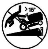
text_image
>15°
text_image
>15°- Be sure the area is clear of bystanders before operating. Stop machine if anyone enters the area.
• Never carry passengers. - Do not mow in reverse unless absolutely necessary. Always look down and behind before and while backing.
- Never carry children, even with the blades shut off. They may fall off and be seriously injured or interfere with safe machine operation. Children who have been given rides in the past may suddenly appear in the mowing area for another ride and be run over or backed over by the machine.
- Keep children out of the mowing area and in the watchful care of a responsible adult other than the operator.
- Be alert and turn machine off if a child enters the area.
• Before and while backing, look behind and down for small children.
- Mow up and down slopes (15° Max), not across.
- Choose a low ground speed so that you will not have to stop or shift while on the slope.
- Avoid starting, stopping, or turning on a slope. If the tires lose traction, disengage the blades and proceed slowly straight down the slope.
- If machine stops while going uphill, disengage blades, shift into reverse and back down slowly.
- Do not turn on slopes unless necessary, and then, turn slowly and gradually downhill, if possible.
PRODUCT SPECIFICATIONS
| Gasoline Capacity and Type: | 4.0 Gallons Unleaded Regular | |
| Oil Type (API-SG-SL): | SAE 30(above 32°F) SAE 5W-30(below 32°F) | |
| Oil Capacity: | w/Filter w/o Filter | 4.0 Pints 3.75 Pints |
| Spark Plug: (GAP: .040") | Champion QC12YC | |
| Ground Speed (MPH): | Forward: Reverse: | 5.5 2.4 |
| Tire Pressure: | Front: 14 PSI Rear: 10 PSI | |
| Charging System: | 16 Amps @ 3600RPM | |
| Battery: | Amp/Hr: Min. CCA: Case Size: U1R | |
| Blade Bolt Torque: | 27–35 Ft. Lbs. | |
CONGRATULATIONS on your purchase of a new tractor. It has been designed, engineered and manufactured to give you the best possible dependability and performance.
Should you experience any problem you cannot easily remedy, please contact a Sears or other qualified service center.
We have competent, well-trained technicians and the proper tools to service or repair this tractor.
Please read and retain this manual. The instructions will enable you to assemble and maintain your tractor properly. Always observe the "SAFETY RULES".
CUSTOMER RESPONSIBILITIES
- Read and observe the safety rules.
- Follow a regular schedule in maintaining, caring for and using your tractor.
- Follow the instructions under "Maintenance" and "Storage" sections of this owner's manual.
WARNING: This tractor is equipped with an internal combustion engine and should not be used on or near any unimproved forest-covered, brush-covered or grass-covered land unless the engine's exhaust system is equipped with a spark arrester meeting applicable local or state laws (if any). If a spark arrester is used, it should be maintained in effective working order by the operator.
In the state of California the above is required by law (Section 4442 of the California Public Resources Code). Other states may have similar laws. Federal laws apply on federal lands. A spark arrester for the muffler is available through your nearest Sears service center (See REPAIR PARTS section of this manual).
REPAIR PROTECTION AGREEMENTS
Congratulations on making a smart purchase. Your new Craftsman® product is designed and manufactured for years of dependable operation. But like all products, it may require repair from time to time. That's when having a Repair Protection Agreement can save you money and aggravation.
Purchase a Repair Protection Agreement now and protect yourself from unexpected hassle and expense.
Here's what's included in the Agreement:
• Expert service by our 12,000 professional repair specialists.
• Unlimited service and no charge for parts and labor on all covered repairs.
- Product replacement if your covered product can't be fixed.
- Discount of 10% from regular price of service and service-related parts not covered by the agreement; also, 10% off regular price of preventive maintenance check.
- Fast help by phone – phone support from a Sears technician on products requiring in-home repair, plus convenient repair scheduling.
Once you purchase the Agreement, a simple phone call is all that it takes for you to schedule service. You can call anytime day or night, or schedule a service appointment online.
Sears has over 12,000 professional repair specialists, who have access to over 4.5 million quality parts and accessories.
That's the kind of professionalism you can count on to help prolong the life of your new purchase for years to come. Purchase your Repair Protection Agreement today! Some limitations and exclusions apply. For prices and additional information call 1-800-827-6655.
SEARS INSTALLATION SERVICE
For Sears professional installation of home appliances, garage door openers, water heaters, and other major home items, in the U.S.A. call 1-800-4-MY-HOME®
UNASSEMBLED PARTS

text_image
(1) Oil Drain Tube(1) Oil Drain Tube For Future Use

text_image
Keys(2) Keys
Slope Sheet
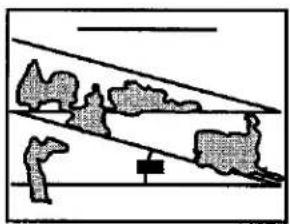
natural_image
Simple line drawing of a landscape with trees, rocks, and a small animal (no text or symbols)Your new tractor has been assembled at the factory. When right or left hand is mentioned in this manual, it means when you are in the operating position (seated behind the steering wheel).
TO REMOVE TRACTOR FROM CARTON
UNPACK CARTON
- Cut along dotted lines on all four panels of carton. Remove end panels and lay side panels flat.
- Remove protective materials from tractor hood and grille.
IMPORTANT: Check for and remove any staples in skid that may puncture tires where tractor is to roll off skid.
CHECK BATTERY
- Lift hood to raised position.
NOTE: If this battery is put into service after month and year indicated on label (label located between terminals) charge battery for minimum of one hour at 6-10 amps. (See "BATTERY" in Maintenance section of this manual for charging instructions).
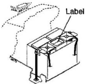
text_image
LabelADJUST SEAT
- Raise seat and loosen adjustment knob.
- Lower seat into operating position and sit in seat.
- Slide seat until a comfortable position is reached which allows you to press clutch/brake pedal all the way down.
- Get off seat without moving its adjusted position.
- Raise seat and tighten adjustment knob securely.
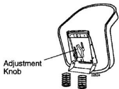
text_image
Adjustment Knob 02634NOTE: You may now roll or drive your tractor off the skid. Follow the appropriate instruction below to remove the tractor from the skid.
TO ROLL TRACTOR OFF SKID (See Operation section for location and function of controls)
- Press lift lever plunger and raise attachment lift lever to its highest position.
- Release parking brake by depressing clutch/brake pedal.
- Place freewheel control in "transmission disengaged" position (See "TO TRANSPORT" in the Operation section of this manual).
- Roll tractor forward off skid.
- Remove banding holding deflector shield up against tractor.
TO DRIVE TRACTOR OFF SKID (See Operation section for location and function of controls)
WARNING: Before starting, read, understand and follow all instructions in the Operation section of this manual. Be sure tractor is in a well-ventilated area. Be sure the area in front of tractor is clear of other people and objects.
- Be sure all the above assembly steps have been completed.
- Check engine oil level and fill fuel tank with gasoline.
- Place freewheel control in "transmission engaged" position. (See "TO TRANSPORT" in the Operation section of this manual).
- Sit on seat in operating position, depress clutch/brake pedal and set the parking brake.
- Place motion control lever in neutral (N) position.
- Press lift lever plunger and raise attachment lift lever to its highest position.
- Start the engine. After engine has started, move throttle control to idle position.
- Release parking brake.
- Slowly move the motion control lever forward and slowly drive tractor off skid.
- Apply brake to stop tractor, set parking brake and place motion control lever in neutral position.
- Turn ignition key to "STOP" position. Continue with the instructions that follow.
For shipping purposes, the right rear gauge wheel assembly is mounted upside down on the mower. Remove the gauge wheel assembly and reinstall from the bottom as shown. To adjust gauge wheels, see the Operation section in this manual.
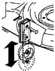
text_image
Technical diagram showing mechanical assembly with directional arrows and labeled componentsCHECK TIRE PRESSURE
The tires on your tractor were overinflated at the factory for shipping purposes. Correct tire pressure is important for best cutting performance.
- Reduce tire pressure to PSI shown in "PRODUCT SPECIFICATIONS" section of this manual.
CHECK DECK LEVELNESS
For best cutting results, mower housing should be properly leveled. See "TO LEVEL MOWER HOUSING" in the Service and Adjustments section of this manual.
CHECK FOR PROPER POSITION OF ALL BELTS
See the figures that are shown for replacing motion and mower blade drive belts in the Service and Adjustments section of this manual. Verify that the belts are routed correctly.
CHECK BRAKE SYSTEM
After you learn how to operate your tractor, check to see that the brake is properly adjusted. See "TO ADJUST BRAKE" in the Service and Adjustments section of this manual.
√CHECKLIST
Before you operate your new tractor, we wish to assure that you receive the best performance and satisfaction from this Quality Product.
Please review the following checklist:
√ All assembly instructions have been completed.
√ No remaining loose parts in carton.
√ Battery is properly prepared and charged. (Minimum 1 hour at 6 amps).
√ Seat is adjusted comfortably and tightened securely.
√ All tires are properly inflated. (For shipping purposes, the tires were overinflated at the factory).
√ Be sure mower deck is properly leveled side-to-side/front-to-rear for best cutting results. (Tires must be properly inflated for leveling).
√ Check mower and drive belts. Be sure they are routed properly around pulleys and inside all belt keepers.
√ Check wiring. See that all connections are still secure and wires are properly clamped.
√ Before driving tractor, be sure freewheel control is in "transmission engaged" position (see "TO TRANSPORT" in the Operation section of this manual).
While learning how to use your tractor, pay extra attention to the following important items:
√ Engine oil is at proper level.
√ Fuel tank is filled with fresh, clean, regular unleaded gasoline.
√ Become familiar with all controls, their location and function. Operate them before you start the engine.
√ Be sure brake system is in safe operating condition.
√ Be sure Operator Presence System and Reverse Operation System (ROS) are working properly (See the Operation and Maintenance sections in this manual).
√ It is important to purge the transmission before operating your tractor for the first time. Follow proper starting and transmission purging instructions (See "TO START ENGINE" and "PURGE TRANSMISSION" in the Operation section of this manual).
OPERATION
These symbols may appear on your tractor or in literature supplied with the product. Learn and understand their meaning.

DANGER indicates a hazard which, if not avoided, will result in death or serious injury.
WARNING indicates a hazard which, if not avoided, could result in death or serious injury.
CAUTION indicates a hazard which, if not avoided, might result in minor or moderate injury.
CAUTION when used without the alert symbol, indicates a situation that could result in damage to the tractor and/or engine.
Failure to follow instructions could result in serious injury or death. The safety alert symbol is used to identify safety information about hazards which can result in death, serious injury and/or property damage.

HOT SURFACES indicates a hazard which, if not avoided, could result in death, serious injury and/or property damage.

FIRE indicates a hazard which, if not avoided, could result in death, serious injury and/or property damage.
KNOW YOUR TRACTOR
READ THIS OWNER'S MANUAL AND SAFETY RULES BEFORE OPERATING YOUR TRACTOR
Compare the illustrations with your tractor to familiarize yourself with the locations of various controls and adjustments. Save this manual for future reference.
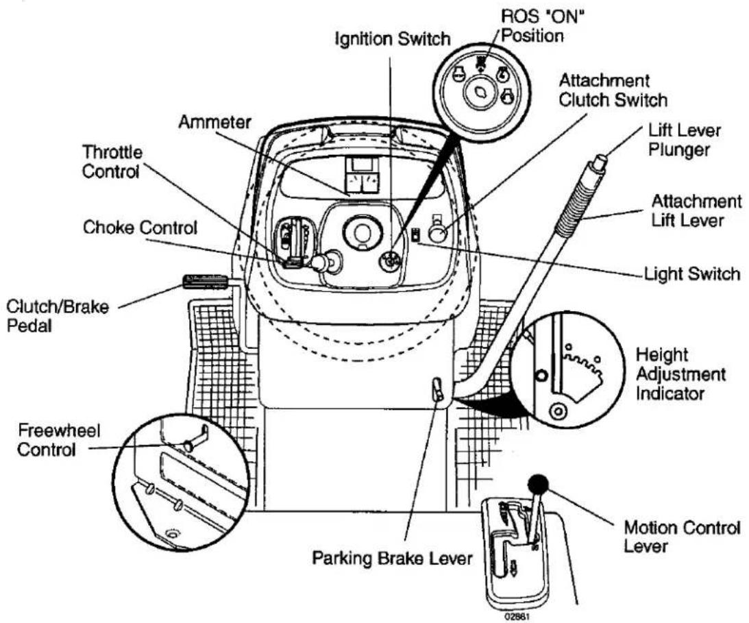
text_image
Ignition Switch ROS "ON" Position Attachment Clutch Switch Ammeter Throttle Control Choke Control Clutch/Brake Pedal Freewheel Control Parking Brake Lever Height Adjustment Indicator Light Switch Lift Lever Plunger Attachment Lift Lever Motion Control Lever 02881Our tractors conform to the safety standards of the American National Standards Institute.
AMMETER - Indicates charging (+) or discharging (-) of battery.
ATTACHMENT CLUTCH SWITCH - Used to engage the mower blades or other attachments mounted to your tractor.
ATTACHMENT LIFT LEVER - Used to raise and lower the mower deck or other attachments mounted to your tractor.
CHOKE CONTROL - Used when starting a cold engine.
CLUTCH/BRAKE PEDAL - Used for declutching and braking the tractor and starting the engine.
FREEWHEEL CONTROL - Disengagages transmission for pushing or slowly towing the tractor with the engine off.
IGNITION SWITCH - Used for starting and stopping the engine.
LIFT LEVER PLUNGER - Used to release attachment lift lever when changing its position.
LIGHT SWITCH - Turns the headlights on and off.
MOTION CONTROL LEVER - Selects the speed and direction of tractor.
PARKING BRAKE LEVER - Locks clutch/brake pedal into the brake position.
REVERSE OPERATION SYSTEM (ROS)
"ON" POSITON - Allows operation of mower deck or other powered attachment while in reverse.
THROTTLE CONTROL - Used to control engine speed.

The operation of any tractor can result in foreign objects thrown into the eyes, which can result in severe eye damage. Always wear safety glasses or eye shields while operating your tractor or performing any adjustments or repairs. We recommend standard safety glasses or a wide vision safety mask worn over spectacles.
HOW TO USE YOUR TRACTOR TO SET PARKING BRAKE
Your tractor is equipped with an operator presence sensing switch. When engine is running, any attempt by the operator to leave the seat without first setting the parking brake will shut off the engine.
- Depress clutch/brake pedal all the way down and hold.
- Pull parking brake lever up and release pressure from clutch/brake pedal. Pedal should remain in brake position. Make sure parking brake will hold tractor secure.
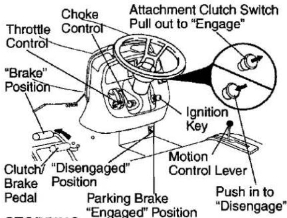
text_image
Choke Control Throttle Control "Brake" Position Attachment Clutch Switch Pull out to "Engage" Ignition Key Motion Control Lever Push in to "Disengage" Clutch/ Brake Pedal "Disengaged" Position Parking Brake "Engaged" PositionSTOPPING
MOWER BLADES -
- To stop mower blades, push attachment clutch switch in to disengaged position.
GROUND DRIVE -
• To stop ground drive, depress clutch/brake pedal all the way down.
- Move motion control lever to neutral (N) position.
IMPORTANT: The motion control lever does not return to neutral (N) position when the clutch/brake pedal is depressed.
ENGINE -
- Move throttle control between half and full speed (fast) position.
NOTE: Failure to move throttle control between half and full speed (fast) position, before stopping, may cause engine to "backfire".
- Turn ignition key to "STOP" position and remove key. Always remove key when leaving tractor to prevent unauthorized use.
- Never use choke to stop engine.
IMPORTANT: Leaving the ignition switch in any position other than "STOP" will cause the battery to discharge and go dead.
NOTE: Under certain conditions when tractor is standing idle with the engine running, hot engine exhaust gases may cause "browning" of grass. To eliminate this possibility, always stop engine when stopping tractor on grass areas.
CAUTION: Always stop tractor completely, as described above, before leaving the operator's position.
TO USE THROTTLE CONTROL
Always operate engine at full throttle.
- Operating engine at less than full throttle reduces the battery charging rate.
• Full throttle offers the best bagging and mower performance.
TO USE CHOKE CONTROL
Use choke control whenever you are starting a cold engine. Do not use to start a warm engine.
• To engage choke control, pull knob out. Slowly push knob in to disengage.
TO MOVE FORWARD AND BACKWARD
The direction and speed of movement is controlled by the motion control lever.
- Start tractor with motion control lever in neutral (N) position.
- Release parking brake.
- Slowly move motion control lever to desired position.
TO ADJUST MOWER CUTTING HEIGHT
The position of the attachment lift lever determines the cutting height.
- Grasp lift lever.
- Press plunger with thumb and move lever to desired position.
The cutting height range is approximately 1-1/2 to 4". The heights are measured from the ground to the blade tip with the engine not running. These heights are approximate and may vary depending upon soil conditions, height of grass and types of grass being mowed.
• The average lawn should be cut to approximately 2-1/2 inches during the cool
season and to over 3 inches during hot months. For healthier and better looking lawns, mow often and after moderate growth.
- For best cutting performance, grass over 6 inches in height should be mowed twice. Make the first cut relatively high; the second to desired height.
TO ADJUST GAUGE WHEELS
Gauge wheels are properly adjusted when they are slightly off the ground when mower is at the desired cutting height in operating position. Gauge wheels then keep the deck in proper position to help prevent scalping in most terrain conditions.
NOTE: Be sure tractor is on a flat level surface.
- Lower mower and adjust mower to desired cutting height(See "TO ADJUST MOWER CUTTING HEIGHT" in this section of manual).
- Remove retainer spring and clevis pin which secure each gauge wheel bar.
- Lower gauge wheels to ground. Raise gauge wheels slightly to align holes in bracket and gauge wheel bar and insert clevis pin. Gauge wheels should be slightly off the ground.
- Replace retainer spring into clevis pin.
- Be sure all gauge wheels are in the same setting.
IMPORTANT: Be sure to readjust gauge wheels if you change the cutting height of the mower deck.
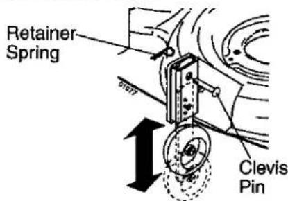
text_image
Retainer Spring Clevis PinTO OPERATE MOWER
Your tractor is equipped with an operator presence sensing switch. Any attempt by the operator to leave the seat with the engine running and the attachment clutch engaged will shut off the engine. You must remain fully and centrally positioned in the seat to prevent the engine from hesitating or cutting off when operating your equipment on rough, rolling terrain or hills.
- Select desired height of cut.
- Start mower blades by engaging attachment clutch control.
TO STOP MOWER BLADES - disengage attachment clutch control.
CAUTION: Do not operate the mower without either the entire grass catcher, on mowers so equipped, or the deflector shield in place.
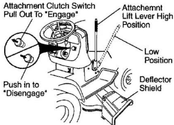
text_image
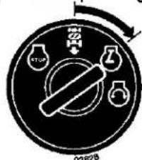
Attachment Clutch Switch Pull Out To "Engage" Attachemnt Lift Lever High Position Low Position Push in to "Disengage" Deflector ShieldYour tractor is equipped with a Reverse Operation System (ROS). Any attempt by the operator to travel in the reverse direction with the attachment clutch engaged will shut off the engine unless ignition key is placed in the ROS "ON" position.
WARNING: Backing up with the attachment clutch engaged while mowing is strongly discouraged. Turning the ROS "ON", to allow reverse operation with the attachment clutch engaged, should only be done when the operator decides it is necessary to reposition the machine with the attachment engaged. Do not mow in reverse unless absolutely necessary.
- Move motion control lever to neutral (N) position.
- With engine running, turn ignition key counterclockwise to ROS "ON" position.
- Look down and behind before backing.
- Slowly move motion control lever to reverse (R) position to start movement.
- When use of the ROS is no longer needed, turn the ignition key clockwise to engine "ON" position.
ROS "ON" Position

text_image
Diagram of a rotary switch mechanism with labeled ports and directional arrowEngine "ON" Position (Normal Operating)
text_image
02628TO OPERATE ON HILLS
WARNING: Do not drive up or down hills with slopes greater than 15° and do not drive across any slope. Use the slope guide at the back of this manual.
- Choose the slowest speed before starting up or down hills.
- Avoid stopping or changing speed on hills.
- If slowing is necessary, move throttle control lever to slower position.
- If stopping is absolutely necessary, push clutch/brake pedal quickly to brake position and engage parking brake.
- Move motion control lever to neutral (N) position.
IMPORTANT: The motion control lever does not return to neutral (N) position when the clutch/brake pedal is depressed.
• To restart movement, slowly release parking brake and clutch/brake pedal.
- Slowly move motion control lever to slowest setting.
• Make all turns slowly.
TO TRANSPORT
When pushing or towing your tractor, be sure to disengage transmission by placing freewheel control in freewheeling position. Freewheel control is located at the rear drawbar of tractor.
- Raise attachment lift to highest position with attachment lift control.
- Pull freewheel control out and down into the slot and release so it is held in the disengaged position.
- Do not push or tow tractor at more than two (2) MPH.
• To re-engage transmission, reverse above procedure.
Transmission Engaged
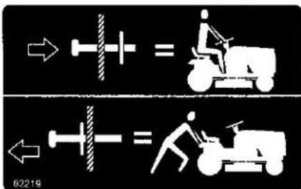
text_image
02219Transmission Disengaged
NOTE: To protect hood from damage when transporting your tractor on a truck or a trailer, be sure hood is closed and secured to tractor. Use an appropriate means of tying hood to tractor (rope, cord, etc.).
TOWING CARTS AND OTHER ATTACHMENTS
Tow only the attachments that are recommended by and comply with specifications of the manufacturer of your tractor. Use common sense when towing. Too heavy of a load, while on a slope, is dangerous. Tires can lose traction with the ground and cause you to lose control of your tractor.
BEFORE STARTING THE ENGINE CHECK ENGINE OIL LEVEL
The engine in your tractor has been shipped, from the factory, already filled with summer weight oil.
- Check engine oil with tractor on level ground.
- Remove oil fill cap/dipstick and wipe clean, reinsert the dipstick and screw cap tight, wait for a few seconds, remove and read oil level. If necessary, add oil until "FULL" mark on dipstick is reached. Do not overfill.
- For cold weather operation you should change oil for easier starting (See the oil viscosity chart in the Maintenance section of this manual).
• To change engine oil, see the Maintenance section in this manual.
ADD GASOLINE
- Fill fuel tank to bottom of tank filler neck. Do not overfill. Use fresh, clean, regular unleaded gasoline with a minimum of 87 octane. (Use of leaded gasoline will increase carbon and lead oxide deposits and reduce valve life). Do not mix oil with gasoline. Purchase fuel in quantities that can be used within 30 days to assure fuel freshness.
CAUTION: Wipe off any spilled oil or fuel. Do not store, spill or use gasoline near an open flame.
IMPORTANT: When operating in temperatures below 32°F(0°C), use fresh, clean winter grade gasoline to help insure good cold weather starting.
CAUTION: Alcohol blended fuels (called gasohol or using ethanol or methanol) can attract moisture which leads to separation and formation of acids during storage. Acidic gas can damage the fuel system of an engine while in storage.
To avoid engine problems, the fuel system should be emptied before storage of 30 days or longer. Drain the gas tank, start the engine and let it run until the fuel lines and carburetor are empty. Use fresh fuel next season. See Storage Instructions for additional information. Never use engine or carburetor cleaner products in the fuel tank or permanent damage may occur.
TO START ENGINE
When starting the engine for the first time or if the engine has run out of fuel, it will take extra cranking time to move fuel from the tank to the engine.
- Be sure freewheel control is in the transmission engaged position.
- Sit on seat in operating position, depress clutch/brake pedal and set parking brake.
- Place motion control lever in neutral (N) position.
- Move attachment clutch to disengaged position.
- Move throttle control to fast position
- Pull choke control out for a cold engine start attempt. For a warm engine start attempt the choke control may not be needed.
NOTE: Before starting, read the warm and cold starting procedures below.
- Insert key into ignition and turn key clockwise to start position and release key as soon as engine starts. Do not run starter continuously for more than fifteen seconds per minute. If the engine does not start after several attempts, push choke control in, wait a few minutes and try again. If engine still does not start, pull the choke control out and retry.
WARM WEATHER STARTING (50° F and above)
- When engine starts, slowly push choke control in until the engine begins to run smoothly. If the engine starts to run roughly, pull the choke control out slightly for a few seconds and then continue to push the control in slowly.
- The attachments and ground drive can now be used. If the engine does not accept the load, restart the engine and allow it to warm up for one minute using the choke as described above.
COLD WEATHER STARTING (50°F and below)
- When engine starts, slowly push choke control in until the engine begins to run smoothly. Continue to push the choke control in small steps allowing the engine to accept small changes in speed and load, until the choke control is fully in. If the engine starts to run roughly, pull the choke control out slightly for a few seconds and then continue to push the control in slowly. This may require an engine warm-up period from several seconds to several minutes, depending on the temperature.
AUTOMATIC TRANSMISSION WARM UP Before driving the unit in cold weather, the transmission should be warmed up as follows:
- Be sure the tractor is on level ground.
- Place the motion control lever in neutral. Release the parking brake and let the clutch/brake slowly return to operating position.
- Allow one minute for transmission to warm up. This can be done during the engine warm up period.
- The attachments can be used during the engine warm-up period after the transmission has been warmed up and may require the choke control be pulled out slightly.
NOTE: If at a high altitude (above 3000 feet) or in cold temperatures (below 32 F) the carburetor fuel mixture may need to be adjusted for best engine performance (see "TO ADJUST CARBURETOR" in the Service and Adjustments section of this manual).
PURGE TRANSMISSION
To ensure proper operation and performance, it is recommended that the transmission be purged before operating tractor for the first time. This procedure will remove any trapped air inside the transmission which may have developed during shipping of your tractor.
IMPORTANT: Should your transmission require removal for service or replacement, it should be purged after reinstallation before operating the tractor.
- Place tractor safely in an area that is flat for approximately 80 feet in front of the tractor and set the parking brake.
- Sitting in the tractor seat, start engine. After the engine is running, move throttle control to slow position. With motion control lever in neutral (N) position, slowly disengage clutch/brake pedal.
- Slowly move motion control lever to full forward position and hold for five (5) seconds, or approximately 40 feet. Slowly move lever to full reverse position and hold for five (5) seconds, or approximately 20 feet. After the tractor moves approximately 20 feet in reverse return the motion control lever to the neutral (N) position. Repeat this procedure three (3) times.
Your transmission is now purged and now ready for normal operation.
MOWING TIPS
- Mower should be properly leveled for best mowing performance. See "TO LEVEL MOWER HOUSING" in the Service and Adjustments section of this manual.
- The left hand side of mower should be used for trimming.
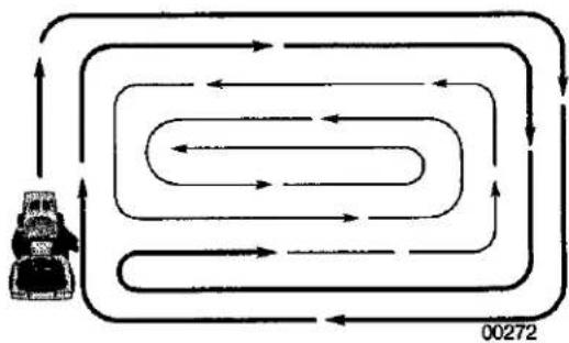
- Drive so that clippings are discharged onto the area that has already been cut. Have the cut area to the right of the tractor. This will result in a more even distribution of clippings and more uniform cutting.
- When mowing large areas, start by turning to the right so that clippings will discharge away from shrubs, fences, driveways, etc. After one or two rounds, mow in the opposite direction making left hand turns until finished.
flowchart
graph TD
    A["Vehicle Icon"] --> B{Spiral Path}
    B --> C["Upward Arrow"]
    B --> D{Downward Arrow}
    D --> E["Left Arrow"]
    D --> F["Right Arrow"]
    E --> G["Upward Arrow"]
    F --> H["Downward Arrow"]
    G --> I["Upward Arrow"]
    H --> J["Downward Arrow"]
    I --> K["Left Arrow"]
    J --> L["Right Arrow"]
- If grass is extremely tall, it should be mowed twice to reduce load and possible fire hazard from dried clippings. Make first cut relatively high; the second to the desired height.
- Do not mow grass when it is wet. Wet grass will plug mower and leave undesirable clumps. Allow grass to dry before mowing.
- Always operate engine at full throttle when mowing to assure better mowing performance and proper discharge of material. Regulate ground speed by selecting a low enough gear to give the mower cutting performance as well as the quality of cut desired.
- When operating attachments, select a ground speed that will suit the terrain and give best performance of the attachment being used.
MAINTENANCE
| MAINTENANCE SCHEDULE FILL IN DATES AS YOU COMPLETE REGULAR SERVICE | BEFORE EACH USE EVERY 8 HOURS | |||||||||
| TRACTOR | Check Brake Operation | ✓ | ✓ | |||||||
| Check Tire Pressure | ✓ | ✓ | ||||||||
| Check Operator Presence and ROS Systems | ✓ | |||||||||
| Check for Loose Fasteners | ✓ | ✓5 | ✓ | |||||||
| Sharpen/Replace Mower Blades | ✓3 | |||||||||
| Lubrication Chart | ✓ | ✓ | ||||||||
| Check Battery Level | ✓4 | |||||||||
| Clean Battery and Terminals | ✓ | ✓ | ||||||||
| Check Transaxle Cooling | ✓ | |||||||||
| Check V-Belts | ✓ | |||||||||
| ENGINE | Check Engine Oil Level | ✓ | ✓ | |||||||
| Change Engine Oil (with oil filter) | ✓12 | ✓ | ||||||||
| Change Engine Oil (without oil filter) | ✓12 | ✓ | ||||||||
| Clean Air Filter | ✓2 | |||||||||
| Clean Air Screen | ✓2 | |||||||||
| Inspect Muffler/Spark Arrester | ✓ | |||||||||
| Replace Oil Filter (If equipped) | ✓1,2 | |||||||||
| Clean Engine Cooling Fins | ✓2 | |||||||||
| Replace Spark Plug | ✓ | ✓ | ||||||||
| Replace Air Filter Paper Cartridge | ✓2 | |||||||||
| Replace Fuel Filter | ✓ | |||||||||
1 - Change more often when operating under a heavy load or in high ambient temperatures.
2 - Service more often when operating in dirty or dusty conditions.
3 - Replace blades more often when mowing in sandy soil.
4 - Not required if equipped with maintenance-free battery.
5 - Tighten front axle pivot bolt to 35 ft.-lbs. maximum.
Do not overtighten.
GENERAL RECOMMENDATIONS
The warranty on this tractor does not cover items that have been subjected to operator abuse or negligence. To receive full value from the warranty, operator must maintain tractor as instructed in this manual.
Some adjustments will need to be made periodically to properly maintain your tractor.
At least once a season, check to see if you should make any of the adjustments described in the Service and Adjustments section of this manual.
- At least once a year you should replace the spark plug, clean or replace air filter, and check blades and belts for wear. A new spark plug and clean air filter assure proper air-fuel mixture and help your engine run better and last longer.
BEFORE EACH USE
- Check engine oil level.
- Check brake operation.
- Check tire pressure.
- Check operator presence and ROS systems for proper operation.
- Check for loose fasteners.
LUBRICATION CHART
text_image
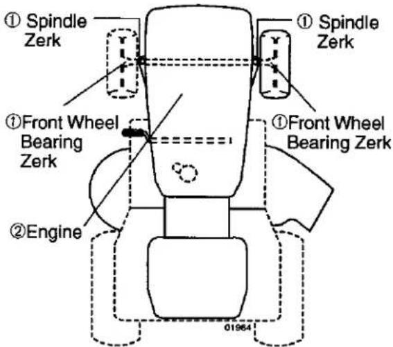
① Spindle Zerk ① Spindle Zerk ① Front Wheel Bearing Zerk ① Front Wheel Bearing Zerk ② Engine 01964① General Purpose Grease
② REFER TO Maintenance "ENGINE" SECTION
IMPORTANT: Do not oil or grease the pivot points which have special nylon bearings. Viscous lubricants will attract dust and dirt that will shorten the life of the self-lubricating bearings. If you feel they must be lubricated, use only a dry, powdered graphite type lubricant sparingly.
TRACTOR
Always observe safety rules when performing any maintenance.
BRAKE OPERATION
If tractor requires more than five (5) feet to stop at highest speed in highest gear on a level, dry concrete or paved surface, then brake must be checked and adjusted. (See "TO ADJUST BRAKE" in the Service and Adjustments section of this manual).
TIRES
- Maintain proper air pressure in all tires (See "PRODUCT SPECIFICATIONS" section of this manual).
- Keep tires free of gasoline, oil, or insect control chemicals which can harm rubber.
- Avoid stumps, stones, deep ruts, sharp objects and other hazards that may cause tire damage.
NOTE: To seal tire punctures and prevent flat tires due to slow leaks, tire sealant may be purchased from your local parts dealer. Tire sealant also prevents tire dry rot and corrosion.
Be sure operator presence and reverse operation systems are working properly. If your tractor does not function as described, repair the problem immediately.
- The engine should not start unless the brake pedal is fully depressed, and the attachment clutch control is in the disengaged position.
CHECK OPERATOR PRESENCE SYSTEM
- When the engine is running, any attempt by the operator to leave the seat without first setting the parking brake should shut off the engine.
- When the engine is running and the attachment clutch is engaged, any attempt by the operator to leave the seat should shut off the engine.
- The attachment clutch should never operate unless the operator is in the seat.
ROS "ON" Position
Engine "ON" Position (Normal Operating)

text_image
Diagram of a rotary switch mechanism with labeled ports and directional arrow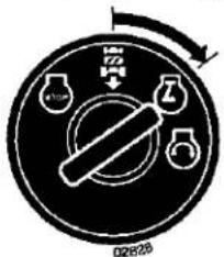
text_image
02826- When the engine is running with the ignition switch in the engine "ON" position and the attachment clutch engaged, any attempt by the operator to shift into reverse should shut off the engine.
- When the engine is running with the ignition switch in the ROS "ON" position and the attachment clutch engaged, any attempt by the operator to shift into reverse should NOT shut off the engine.
BLADE CARE
For best results mower blades must be kept sharp. Replace bent or damaged blades.
CAUTION: Use only a replacement blade approved by the manufacturer of your tractor. Using a blade not approved by the manufacturer of your tractor is hazardous, could damage your tractor and void your warranty.
BLADE REMOVAL
- Raise mower to highest position to allow access to blades.
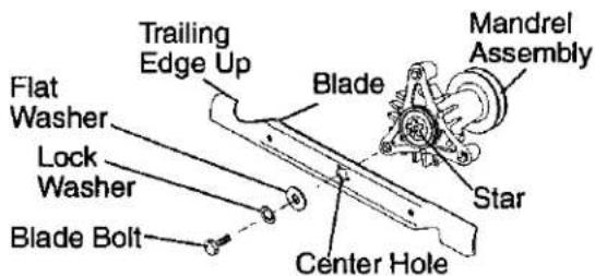
- Remove blade bolt, lock washer and flat washer securing blade.
- Install new or resharpened blade with trailing edge up towards deck as shown.
IMPORTANT: To ensure proper assembly, center hole in blade must align with star on mandrel assembly. - Reassemble blade bolt, lock washer and flat washer in exact order as shown.
- Tighten blade bolt securely (27-35 Ft. Lbs. torque).
IMPORTANT: Blade bolt is heat treated. If bolt needs replacing, replace only with approve bolt shown in the Repair Parts.
text_image
Trailing Edge Up Blade Flat Washer Lock Washer Blade Bolt Center Hole Mandrel Assembly StarTO SHARPEN BLADE
NOTE: We do not recommend sharpening blade - but if you do, be sure the blade is balanced.
Care should be taken to keep the blade balanced. An unbalanced blade will cause excessive vibration and eventual damage to mower and engine.
- The blade can be sharpened with a file or on a grinding wheel. Do not attempt to sharpen while on the mower.
- To check blade balance, you will need a 5/8" diameter steel bolt, pin, or a cone balancer. (When using a cone balancer, follow the instructions supplied with balancer.)
NOTE: Do not use a nail for balancing blade. The lobes of the center hole may appear to be centered, but are not.
- Slide blade on to an unthreaded portion of the steel bolt or pin and hold the bolt or pin parallel with the ground. If blade is balanced, it should remain in a horizontal position. If either end of the blade moves downward, sharpen the heavy end until the blade is balanced.
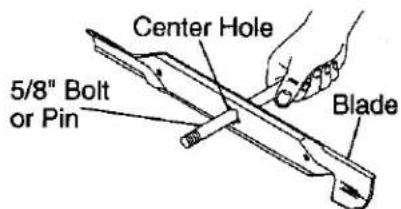
text_image
Center Hole 5/8" Bolt or Pin BladeBATTERY
Your tractor has a battery charging system which is sufficient for normal use. However, periodic charging of the battery with an automotive charger will extend its life.
- Keep battery and terminals clean.
- Keep battery bolts tight.
- Keep small vent holes open.
• Recharge at 6-10 amperes for 1 hour.
NOTE: The original equipment battery on your tractor is maintenance free. Do not attempt to open or remove caps or covers. Adding or checking level of electrolyte is not necessary.
TO CLEAN BATTERY AND TERMINALS Corrosion and dirt on the battery and terminals can cause the battery to "leak" power.
- Remove terminal guard.
- Disconnect BLACK battery cable first then RED battery cable and remove battery from tractor.
- Rinse the battery with plain water and dry.
- Clean terminals and battery cable ends with wire brush until bright.
- Coat terminals with grease or petroleum jelly.
- Reinstall battery (See "REPLACING BATTERY" in the SERVICE AND ADJUSTMENTS section of this manual).
TRANSAXLE COOLING
The transmission fan and cooling fins should be kept clean to assure proper cooling.
Do not attempt to clean fan or transmission while engine is running or while the transmission is hot. To prevent possible damage to seals, do not use high pressure water or steam to clean transaxle.
- Inspect cooling fan to be sure fan blades are intact and clean.
- Inspect cooling fins for dirt, grass clippings and other materials. To prevent damage to seals, do not use compressed air or high pressure sprayer to clean cooling fins.
TRANSAXLE PUMP FLUID
The transaxle was sealed at the factory and fluid maintenance is not required for the life of the transaxle. Should the transaxle ever leak or require servicing, contact a Sears or other qualified service center.
V-BELTS
Check V-belts for deterioration and wear after 100 hours of operation and replace if necessary. The belts are not adjustable. Replace belts if they begin to slip from wear.
ENGINE
LUBRICATION
Only use high quality detergent oil rated with API service classification SG-SL. Select the oil's SAE viscosity grade according to your expected operating temperature.
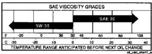
bar
| Metric | Value | |--------|-------| | F | -20 | | C | -30 | | 5W-30 | 5W-30 | | 30 | 32 | | 40 | 60 | | 60 | 80 | | 80 | 100 |NOTE: Although multi-viscosity oils (5W30, 10W30 etc.) improve starting in cold weather, they will result in increased oil consumption when used above 32°F. Check your engine oil level more frequently to avoid possible engine damage from running low on oil.
Change the oil after every 50 hours of operation or at least once a year if the tractor is not used for 50 hours in one year.
Check the crankcase oil level before starting the engine and after each eight (8) hours of operation. Tighten oil fill cap/dipstick securely each time you check the oil level.
TO CHANGE ENGINE OIL
Determine temperature range expected before oil change. All oil must meet API service classification SG-SL.
- Be sure tractor is on level surface.
- Oil will drain more freely when warm.
-
Catch oil in a suitable container.
-
Remove oil fill cap/dipstick. Be careful not to allow dirt to enter the engine when changing oil.
-
Remove yellow cap from end of drain valve and install the drain tube onto the fitting.
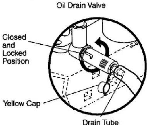
text_image
Oil Drain Valve Closed and Locked Position Yellow Cap Drain Tube- Unlock drain valve by pushing inward slightly and turning counterclockwise.
- To open, pull out on the drain valve.
- After oil has drained completely, close and lock the drain valve by pushing inward and turning clockwise until the pin is in the locked position as shown.
- Remove the drain tube and replace the cap onto the end of the drain valve.
- Refill engine with oil through oil fill dipstick tube. Pour slowly. Do not overfill. For approximate capacity see "PRODUCT SPECIFICATIONS" section of this manual.
- Use gauge on oil fill cap/dipstick for checking level. For accurate reading, tighten dipstick cap securely onto the tube before removing dipstick. Keep oil at "FULL" line on dipstick. Tighten cap onto the tube securely when finished.
ENGINE OIL FILTER
Replace the engine oil filter every season or every other oil change if the tractor is used more than 100 hours in one year.
AIR FILTER
Your engine will not run properly using a dirty air filter. Clean the foam pre-cleaner after every 25 hours of operation or every season. Service paper cartridge every 100 hours of operation or every season, whichever occurs first.
Service air cleaner more often under dusty conditions.
- Remove cover.
TO SERVICE PRE-CLEANER
- Wash it in liquid detergent and water.
- Squeeze it dry in a clean cloth.
- Saturate it in engine oil. Wrap it in clean, absorbent cloth and squeeze to remove excess oil.
NOTE: If very dirty or damaged, replace pre-cleaner.
TO SERVICE CARTRIDGE
- Clean cartridge by tapping gently on flat surface. If very dirty or damaged, replace cartridge.
- Reinstall precleaner cartridge, cover and secure.
IMPORTANT: Petroleum solvents, such as kerosene, are not to be used to clean the cartridge. They may cause deterioration of the cartridge. Do not oil cartridge. Do not use pressurized air to clean or dry cartridge.
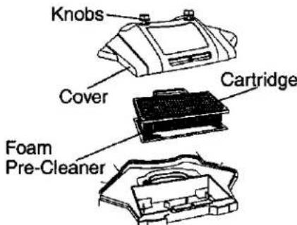
text_image
Knobs Cover Cartridge Foam Pre-CleanerCLEAN AIR SCREEN
Air screen must be kept free of dirt and chaff to prevent engine damage from overheating. Clean with a wire brush or compressed air to remove dirt and stubborn dried gum fibers.
CLEAN AIR INTAKE/COOLING AREAS
To insure proper cooling, make sure the grass screen, cooling fins, and other external surfaces of the engine are kept clean at all times.
Every 100 hours of operation (more often under extremely dusty, dirty conditions), remove the blower housing and other cooling shrouds. Clean the cooling fins and external surfaces as necessary. Make sure the cooling shrouds are reinstalled.
NOTE: Operating the engine with a blocked grass screen, dirty or plugged cooling fins, and/or cooling shrouds removed will cause engine damage due to overheating.
MUFFLER
Inspect and replace corroded muffler and spark arrester (if equipped) as it could create a fire hazard and/or damage.
SPARK PLUG(S)
Replace spark plug(s) at the beginning of each mowing season or after every 100 hours of operation, whichever occurs first. Spark plug type and gap setting are shown in "PRODUCT SPECIFICATIONS" section of this manual.
IN-LINE FUEL FILTER
The fuel filter should be replaced once each season. If fuel filter becomes clogged, obstructing fuel flow to carburetor, replacement is required.
- With engine cool, remove filter and plug fuel line sections.
- Place new fuel filter in position in fuel line with arrow pointing towards carburetor.
- Be sure there are no fuel line leaks and clamps are properly positioned.
- Immediately wipe up any spilled gaso- line.

text_image
Fuel Filter ClampCLEANING
- Clean engine, battery, seat, finish, etc. of all foreign matter.
- Keep finished surfaces and wheels free of all gasoline, oil, etc.
- Protect painted surfaces with automotive type wax.
We do not recommend using a garden hose or pressure washer to clean your tractor unless the engine and transmission are covered to keep water out. Water in engine or transmission will shorten the useful life of your tractor. Use compressed air or a leaf blower to remove grass, leaves and trash from tractor and mower.
SERVICE AND ADJUSTMENTS

WARNING: TO AVOID SERIOUS INJURY, BEFORE PERFORMING ANY SERVICE OR ADJUSTMENTS:
- Depress clutch/brake pedal fully and set parking brake.
- Place motion control lever in neutral (N) position.
- Place attachment clutch in "DISENGAGED" position.
- Turn ignition key to "STOP" and remove key.
- Make sure the blades and all moving parts have completely stopped.
- Disconnect spark plug wire from spark plug and place wire where it cannot come in contact with plug.
TRACTOR
TO REMOVE MOWER
Mower will be easier to remove from the right side of tractor.
- Place attachment clutch switch in "DIS-ENGAGED" position.
- Move attachment lift lever forward to lower mower to its lowest position.
- Roll belt off electric clutch pulley.
- Disconnect anti-sway bar from chassis bracket by removing retainer spring.
- Disconnect suspension arms from rear deck brackets by removing retainer springs.
- Disconnect front links from deck by removing retainer springs.
- Raise lift lever to raise suspension arms. Slide mower out from under tractor.
IMPORTANT: If an attachment other than the mower deck is to be mounted on the tractor, remove the front links.
TO INSTALL MOWER
- Raise attachment lift lever to its highest position.
- Slide mower under tractor with deflector shield to right side of tractor.
- Lower lift lever to its lowest position.
- Connect front links to mower deck and secure with retainer springs.
- Connect suspension arms to rear deck brackets and secure with retainer springs.
- Connect anti-sway bar to chassis bracket and secure with retainer spring.
- Install belt into electric clutch pulley groove.
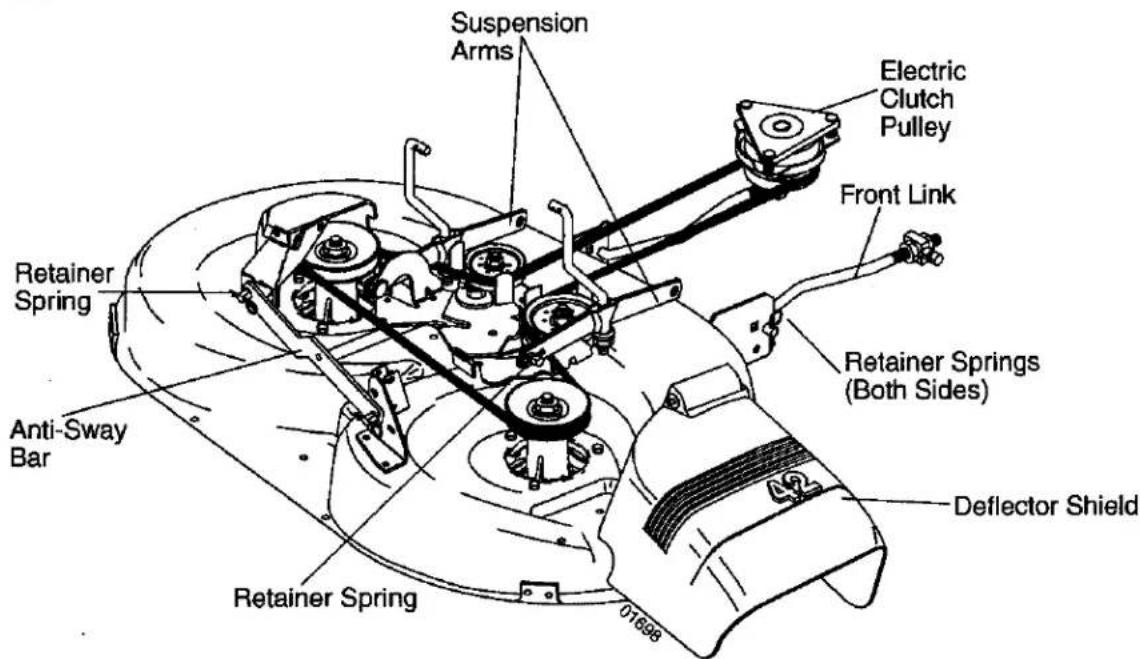
text_image
Suspension Arms Electric Clutch Pulley Front Link Retainer Spring Retainer Springs (Both Sides) Anti-Sway Bar Deflector Shield 01698Adjust the mower while tractor is parked on level ground or driveway. Make sure tires are properly inflated (See "PRODUCT SPECIFICATIONS" section of this manual). If tires are over or underinflated, you will not properly adjust your mower.
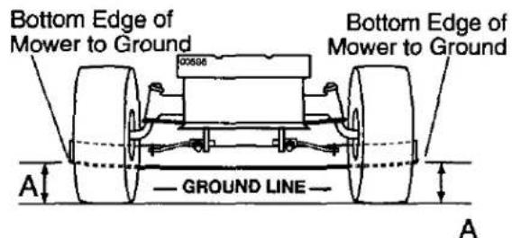
SIDE-TO-SIDE ADJUSTMENT
- Raise mower to its highest position.
- At the midpoint of both sides of mower, measure height from bottom edge of mower to ground. Distance "A" on both sides of mower should be the same or within 1/4" of each other.
- If adjustment is necessary, make adjustment on one side of mower only.
• To raise one side of mower, tighten lift link adjustment nut on that side. - To lower one side of mower, loosen lift link adjustment nut on that side.
NOTE: Each full turn of adjustment nut will change mower height about 1/8". 6.0 Recheck measurements after adjusting.
Check adjustment on right side of tractor. Measure distance "D" directly in front of and behind the mandrel at bottom edge of mower housing as shown.
- Before making any necessary adjustments, check that both front links are equal in length.
- If links are not equal in length, adjust one link to same length as other link.
- To lower front of mower loosen nut "E" on both front links an equal number of turns.
- When distance "D" is 1/8" to 1/2" lower at front than rear, tighten nuts "F" against trunnion on both front links.
- To raise front of mower, loosen nut "F" from trunnion on both front links. Tighten nut "E" on both front links an equal number of turns. The two front links must remain equal in length.
- When distance "D" is 1/8" to 1/2" lower at front than rear, tighten nut "F" against trunnion on both front links.
• Recheck side-to-side adjustment.
text_image
Bottom Edge of Mower to Ground Bottom Edge of Mower to Ground A GROUND LINE A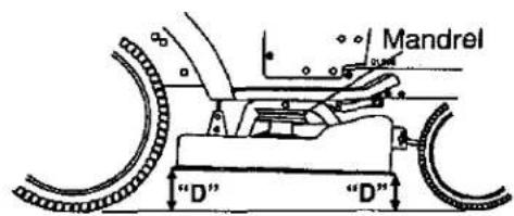
text_image
Mandrel "D" "D"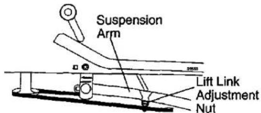
text_image
Suspension Arm Lift Link Adjustment NutBOTH FRONT LINKS MUST BE EQUAL IN
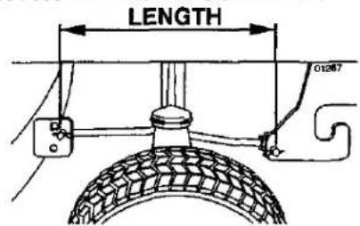
text_image
LENGTH 01267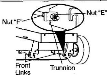
text_image
Nut "F" Nut "E" Front Links TrunnionFRONT-TO-BACK ADJUSTMENT
IMPORTANT: Deck must be level side-to-side. If the following front-to-back adjustment is necessary, be sure to adjust both front links equally so mower will stay level side-to-side.
To obtain the best cutting results, the mower housing should be adjusted so that the front is approximately 1/8" to 1/2" lower than the rear when the mower is in its highest position.
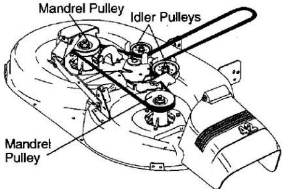
TO REPLACE MOWER BLADE DRIVE BELT
The mower blade drive belt may be replaced without tools. Park the tractor on level surface. Engage parking brake.
BELT REMOVAL -
- Remove mower from tractor (See "TO REMOVE MOWER" in this section of manual).
- Work belt off both mandrel pulleys and idler pulleys.
- Pull belt away from mower.
BELT INSTALLATION -
- Work belt around both mandrel pulleys and idler pulleys
- Make sure belt is in all pulley grooves and inside all belt guides.
- Install mower (See "To Install Mower" in this section of this manual).
text_image
Mandrel Pulley Idler Pulleys Mandrel PulleyTO CHECK AND ADJUST BRAKE
Your tractor is equipped with an adjustable brake system which is mounted on the right side of the transaxle.
If tractor requires more than five (5) feet to stop at highest speed in highest gear on a level, dry concrete or paved surface, then brake must be checked and adjusted.
TO CHECK BRAKE
- Park tractor on a level, dry concrete or paved surface, depress clutch/brake pedal all the way down and engage parking brake.
- Disengage transmission by placing freewheel control in "transmission disengaged" position. Pull freewheel control out and into the slot and release so it is held in the disengaged position.
The rear wheels must lock and skid when you try to manually push the tractor forward. If the rear wheels rotate, the brake needs to be adjusted or the pads need to be replaced.
TO ADJUST BRAKE
- Depress clutch/brake pedal all the way down and engage parking brake.
- Measure distance between brake operating arm and nut "A" on brake rod.
- If distance is other than 1-9/16", loosen jam nut and turn nut "A" until distance becomes 1-9/16". Retighten jam nut against nut "A".
- Engage transmission by placing freewheel control in "transmission engaged" position.
- Road test tractor for proper stopping distance as stated above. Readjust if necessary. If stopping distance is still greater than five (5) feet in highest gear, further maintenance is necessary. Replace brake pads or contact a Sears or other qualified service center.
With parking brake "Engaged"
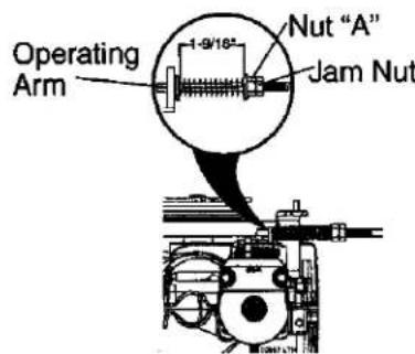
text_image
Operating Arm 1-9/16" Nut "A" Jam NutTO REPLACE MOTION DRIVE BELT
Park the tractor on level surface. Engage parking brake. For assistance, there is a belt installation guide decal on bottom side of left footrest.
BELT REMOVAL -
- Remove mower (See "TO REMOVE MOWER" in this section of manual).
NOTE: Observe entire motion drive belt and position of all belt guides and keepers. - Disconnect clutch wire harness.
- Remove clutch locator.
- Remove belt from stationary idler and clutching idler.
- Remove belt downward from engine pulley and around electric clutch.
- Pull belt slack toward rear of tractor. Carefully remove belt upwards from transmission input pulley.
- Remove belt from center span keeper and pull belt away from tractor.
BELT INSTALLATION -
- Carefully work new belt down onto the input pulley.
-
Slide belt into the center span keeper.
-
Pull belt toward front of tractor and roll belt around electric clutch and onto engine pulley.
- Install belt through stationary idler and clutching idler.
- Reinstall clutch locator and tighten nut securely.
- Reconnect clutch harness.
- Make sure belt is in all pulley grooves and inside all belt guides and keepers.
- Install mower (See "TO INSTALL MOWER" in this section of manual).
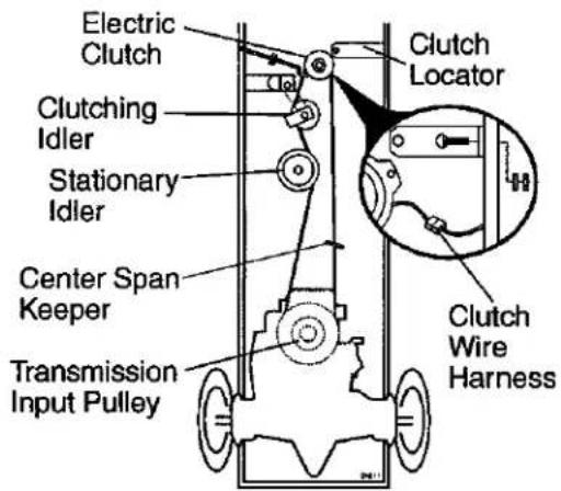
text_image
Electric Clutch Clutch Locator Clutch Wre Harness Clutch Idler Stationary Idler Center Span Keeper Transmission Input PulleyTRANSAXLE MOTION CONTROL LEVER NEUTRAL ADJUSTMENT
The motion control lever has been preset at the factory and adjustment should not be necessary.
- Loosen adjustment bolt in front of the right rear wheel, and lightly tighten.
-
Start engine and move motion control lever until tractor does not move forward or backward.
-
Hold motion control lever in that position and turn engine off.
-
While holding motion control lever in place, loosen the adjustment bolt.
-
Move motion control lever to the neutral (N) (lock gate) position.
-
Tighten adjustment bolt securely. NOTE: If additional clearance is needed to get to adjustment bolt, move mower deck height to the lowest position.
After above adjustment is made, if the tractor still creeps forward or backward while motion control lever is in neutral position, follow these steps:
- Loosen the adjustment bolt.
- Move the motion control lever 1/4 to 1/2 inch in the direction it is trying to creep.
- Tighten adjustment bolt securely.
- Start engine and test.
- If tractor still creeps, repeat above steps until satisfied.
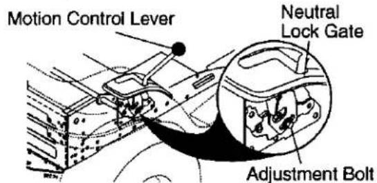
text_image
Motion Control Lever Neutral Lock Gate Adjustment BoltTRANSMISSION REMOVAL/REPLACEMENT
Should your transmission require removal for service or replacement, it should be purged after reinstallation and before operating the tractor. See "PURGE TRANSMISSION" in the Operation section of this manual.
TO ADJUST STEERING WHEEL ALIGNMENT
If steering wheel crossbars are not horizontal (left to right) when wheels are positioned straight forward, remove steering wheel and reassemble with crossbars horizontal. Tighten securely.
FRONT WHEEL TOE-IN/CAMBER
The front wheel toe-in and camber are not adjustable on your tractor. If damage has occurred to affect the front wheel toe-in or camber, contact a Sears or other qualified service center.
TO REMOVE WHEEL FOR REPAIRS
- Block up axle securely.
- Remove axle cover, retaining ring and washers to allow wheel removal (rear wheels have a square key - Do not lose).
- Repair tire and reassemble.
NOTE: On rear wheels only: align grooves in rear wheel hub and axle. Insert square key. - Replace washers and snap retaining ring securely in axle groove.
- Replace axle cover.
NOTE: To seal tire punctures and prevent flat tires due to slow leaks, purchase and use tire sealant from Sears. Tire sealant also prevents tire dry rot and corrosion.
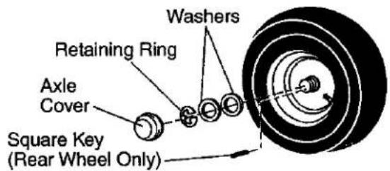
text_image
Washers Retaining Ring Axle Cover Square Key (Rear Wheel Only)TO START ENGINE WITH A WEAK BATTERY
WARNING: Lead-acid batteries generate explosive gases. Keep sparks, flame and smoking materials away from batteries. Always wear eye protection when around batteries.
If your battery is too weak to start the engine, it should be recharged. (See "BATTERY" in the MAINTENANCE section of this manual).
If "jumper cables" are used for emergency starting, follow this procedure:
IMPORTANT: Your tractor is equipped with a 12 volt system. The other vehicle must also be a 12 volt system. Do not use your tractor battery to start other vehicles.
TO ATTACH JUMPER CABLES -
- Connect one end of the RED cable to the POSITIVE (+) terminal of each battery(A-B), taking care not to short against tractor chassis.
- Connect one end of the BLACK cable to the NEGATIVE (-) terminal (C) of fully charged battery.
- Connect the other end of the BLACK cable (D) to good chassis ground, away from fuel tank and battery.
TO REMOVE CABLES, REVERSE ORDER -
- BLACK cable first from chassis and then from the fully charged battery.
- RED cable last from both batteries.
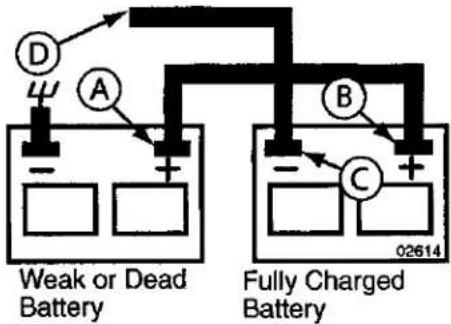
text_image
D A B C Weak or Dead Battery Fully Charged Battery 02614REPLACING BATTERY
WARNING: Do not short battery terminals by allowing a wrench or any other object to contact both terminals at the same time. Before connecting battery, remove metal bracelets, wristwatch bands, rings, etc. Positive terminal must be connected first to prevent sparking from accidental grounding.
- Lift hood to raised position.
- Remove terminal guard.
- Disconnect BLACK battery cable then RED battery cable and carefully remove battery from tractor.
- Install new battery with terminals in same position as old battery.
- Reinstall terminal guard.
- First connect RED battery cable to positive (+) battery terminal with hex bolt and keps nut as shown. Tighten securely.
- Connect BLACK grounding cable to negative (-) battery terminal with remaining hex bolt and keps nut. Tighten securely
- Close terminal access doors.
- Close hood.
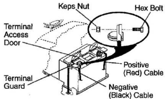
text_image
Keps Nut Hex Bolt Terminal Access Door Positive (Red) Cable Terminal Guard Negative (Black) CableTO REPLACE HEADLIGHT BULB
- Raise hood.
- Pull bulb holder out of the hole in the backside of the grill.
- Replace bulb in holder and push bulb holder securely back into the hole in the backside of the grill.
- Close hood.
INTERLOCKS AND RELAYS
Loose or damaged wiring may cause your tractor to run poorly, stop running, or prevent it from starting.
- Check wiring. See electrical wiring diagram in the Repair Parts section.
TO REPLACE FUSE
Replace with 20 amp automotive-type plug-in fuse. The fuse holder is located behind the dash.
TO REMOVE HOOD AND GRILL ASSEMBLY
- Raise hood.
- Unsnap headlight wire connector.
- Stand in front of tractor. Grasp hood at sides, tilt toward engine and lift off of tractor.
- When replacing hood, be sure to reconnect the headlight wire connector.
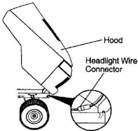
text_image
Hood Headlight Wire ConnectorENGINE
TO ADJUST THROTTLE CONTROL CABLE
The throttle control has been preset at the factory and adjustment should not be necessary. Check adjustment as described below before loosening cable. If adjustment is necessary, proceed as follows:
- With engine not running, move throttle control lever to fast position.
- Check that swivel is against stop. If it is not, loosen cable clamp screw and pull cable back until swivel is against stop. Tighten cable clamp screw securely.
TO ADJUST CHOKE CONTROL
The choke control has been preset at the factory and adjustment should not be necessary. Check adjustment as described below before loosening cable. If adjustment is necessary, proceed as follows:
- With engine not running, move choke control (located on dash panel) to full choke position.
- Loosen knob and remove cover as-sembly from air cleaner.
- Choke should be closed. If it is not, loosen casing clamp screw and move choke cable until choke is completely closed. Tighten casing clamp screw securely.
- Replace air cleaner cover assembly and tighten knob.
TO ADJUST CARBURETOR
Your carburetor is not adjustable. If your engine does not operate properly due to suspected carburetor problems, take your tractor to an authorized service center for repair and/or adjustment. High speed stop is factory adjusted. Do not adjust - damage may result.
IMPORTANT: Never tamper with the engine governor, which is factory set for proper engine speed. Overspeeding the engine above the factory high speed setting can be dangerous. If you think the engine-governed high speed needs adjusting, contact a qualified service center, which has proper equipment and experience to make any necessary adjustments.
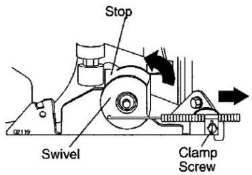
text_image
Stop Swivel Clamp Screw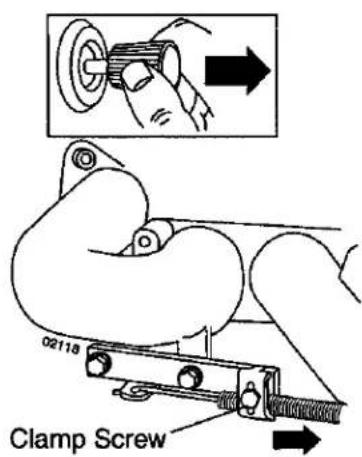
text_image
Clamp Screw 02118STORAGE
Immediately prepare your tractor for storage at the end of the season or if the tractor will not be used for 30 days or more.
WARNING: Never store the tractor with gasoline in the tank inside a building where fumes may reach an open flame or spark. Allow the engine to cool before storing in any enclosure.
TRACTOR
Remove mower from tractor for winter storage. When mower is to be stored for a period of time, clean it thoroughly, remove all dirt, grease, leaves, etc. Store in a clean, dry area.
- Clean entire tractor (See "CLEANING" in the Maintenance section of this manual).
- Inspect and replace belts, if necessary (See belt replacement instructions in the Service and Adjustments section of this manual).
- Lubricate as shown in the Maintenance section of this manual.
- Be sure that all nuts, bolts and screws are securely fastened. Inspect moving parts for damage, breakage and wear. Replace if necessary.
- Touch up all rusted or chipped paint surfaces; sand lightly before painting.
BATTERY
• Fully charge the battery for storage.
• After a period of time in storage, battery may require recharging.
- To help prevent corrosion and power leakage during long periods of storage, battery cables should be disconnected and battery cleaned thoroughly (see "TO CLEAN BATTERY AND TERMINALS" in the Maintenance section of this manual).
- After cleaning, leave cables disconnected and place cables where they cannot come in contact with battery terminals.
- If battery is removed from tractor for storage, do not store battery directly on concrete or damp surfaces.
ENGINE
FUEL SYSTEM
IMPORTANT: It is important to prevent gum deposits from forming in essential fuel system parts such as carburetor, fuel hose, or tank during storage.
Also, alcohol blended fuels (called gasohol or using ethanol or methanol) can attract moisture which leads to separation and formation of acids during storage. Acidic gas can damage the fuel system of an engine while in storage.
- Empty the fuel tank by starting the engine and letting it run until the fuel lines and carburetor are empty.
- Never use engine or carburetor cleaner products in the fuel tank or permanent damage may occur.
• Use fresh fuel next season.
NOTE: Fuel stabilizer is an acceptable alternative in minimizing the formation of fuel gum deposits during storage. Add stabilizer to gasoline in fuel tank or storage container. Always follow the mix ratio found on stabilizer container. Run engine at least 10 minutes after adding stabilizer to allow the stabilizer to reach the carburetor. Do not empty the gas tank and carburetor if using fuel stabilizer.
ENGINE OIL
Drain oil (with engine warm) and replace with clean engine oil. (See "ENGINE" in the Maintenance section of this manual).
CYLINDER(S)
- Remove spark plug(s).
- Pour one ounce of oil through spark plug hole(s) into cylinder(s).
- Turn ignition key to start position for a few seconds to distribute oil.
- Replace with new spark plug(s).
OTHER
- Do not store gasoline from one season to another.
- Replace your gasoline can if your can starts to rust. Rust and/or dirt in your gasoline will cause problems.
- If possible, store your tractor indoors and cover it to give protection from dust and dirt.
- Cover your tractor with a suitable protective cover that does not retain moisture. Do not use plastic. Plastic cannot breathe which allows condensation to form and will cause your tractor to rust.
IMPORTANT: Never cover tractor while engine and exhaust areas are still warm.
TROUBLESHOOTING CHART:
See appropriate section in manual unless directed to Sears service center
| PROBLEM | CAUSE | CORRECTION |
| Will not start | 1. Out of fuel.2. Engine not “CHOKED” properly.3. Engine flooded.4. Bad spark plug.5. Dirty air filter.6. Dirty fuel filter.7. Water in fuel.8. Loose or damaged wiring.9. Carburetor out of adjustment.10. Engine valves out of adjustment. | 1. Fill fuel tank.2. See “TO START ENGINE” in Operation section.3. Wait several minutes before attempting to start.4. Replace spark plug.5. Clean/replace air filter.6. Replace fuel filter.7. Empty fuel tank and carburetor, refill tank with fresh gasoline and replace fuel filter.8. Check all wiring.9. See “To Adjust Carburetor” in Service and Adjustments section.10. Contact a Sears or other qualified service center. |
| Hard to start | 1. Dirty air filter.2. Bad spark plug.3. Weak or dead battery.4. Dirty fuel filter.5. Stale or dirty fuel.6. Loose or damaged wiring.7. Carburetor out of adjustment.8. Engine valves out of adjustment. | 1. Clean/replace air filter.2. Replace spark plug.3. Recharge or replace battery.4. Replace fuel filter.5. Empty fuel tank and refill tank with fresh, clean gasoline.6. Check all wiring.7. See “To Adjust Carburetor” in Service and Adjustments section.8. Contact a Sears or other qualified service center. |
| Engine will not turn over | 1. Brake pedal not depressed.2. Attachment clutch is engaged.3. Weak or dead battery.4. Blown fuse.5. Corroded battery terminals.6. Loose or damaged wiring.7. Faulty ignition switch.8. Faulty solenoid or starter.9. Faulty operator presence switch(es). | 1. Depress brake pedal.2. Disengage attachment clutch.3. Recharge or replace battery.4. Replace fuse.5. Clean battery terminals.6. Check all wiring.7. Check/replace ignition switch.8. Check/replace solenoid or starter.9. Contact a Sears or other qualified service center. |
| Engine clicks but will not start | 1. Weak or dead battery.2. Corroded battery terminals.3. Loose or damaged wiring.4. Faulty solenoid or starter. | 1. Recharge or replace battery.2. Clean battery terminals.3. Check all wiring.4. Check/replace solenoid or starter. |
| Loss of power | 1. Cutting too much grass/too fast.2. Throttle in “CHOKE” position.3. Build-up of grass, leaves and trash under mower.4. Dirty air filter. | 1. Raise cutting height/reduce speed.2. Adjust throttle control.3. Clean underside of mower housing.4. Clean/replace air filter. |
TROUBLESHOOTING CHART:
See appropriate section in manual unless directed to Sears service center
| PROBLEM | CAUSE | CORRECTION |
| Loss of power (continued) | 5. Low oil level/dirty oil.6. Faulty spark plug.7. Dirty fuel filter.8. Stale or dirty fuel.9. Water in fuel.10. Spark plug wire loose.11. Dirty engine air screen/fins.12. Dirty/clogged muffler.13. Loose or damaged wiring.14. Carburetor out of adjustment.15. Engine valves out of adjustment. | 5. Check oil level/change oil.6. Clean and regap or change spark plug.7. Replace fuel filter.8. Empty fuel tank and refill tank with fresh, clean gasoline.9. Empty fuel tank and carburetor, refill tank with fresh gasoline and replace fuel filter.10. Connect and tighten spark plug wire.11. Clean engine air screen/fins.12. Clean/replace muffler.13. Check all wiring.14. See “To Adjust Carburetor” in Service and Adjustments section.15. Contact a Sears or other qualified service center. |
| Excessive vibration | 1. Worn, bent or loose blade.2. Bent blade mandrel.3. Loose/damaged part(s). | 1. Replace blade. Tighten blade bolt.2. Contact a Sears or other qualified service center.3. Tighten loose part(s).Replace damaged parts. |
| Engine dies when tractor is shifted into reverse | 1. Reverse operation system (ROS) is not "ON" while mower or other attachment is engaged. | 1. Turn ignition key to ROS "ON" position.See Operation section. |
| Engine continues to run when operator leaves seat with attachment clutch engaged | 1. Faulty operator-safety presence control system. | 1. Check wiring, switches and connections. If not corrected, contact a Sears or other qualified service center. |
| Poor cut - uneven | 1. Worn, bent or loose blade.2. Mower deck not level.3. Buildup of grass, leaves, and trash under mower.4. Bent blade mandrel.5. Clogged mower deck vent from build-up of grass, leaves, and trash around mandrels. | 1. Replace blade. Tighten blade bolt.2. Level mower deck.3. Clean underside of mower housing.4. Contact a Sears or other qualified service center.5. Clean around mandrels to open vent holes. |
TROUBLESHOOTING CHART:
See appropriate section in manual unless directed to Sears service center
| PROBLEM | CAUSE | CORRECTION |
| Mower blades will not rotate | 1. Obstruction in clutch mechanism.2. Worn/damaged mower drive belt.3. Frozen idler pulley.4. Frozen blade mandrel. | 1. Remove obstruction.2. Replace mower drive belt.3. Replace idler pulley.4. Contact a Sears or other qualified service center. |
| Poor grass discharge | 1. Engine speed too slow.2. Travel speed too fast.3. Wet grass.4. Mower deck not level.5. Low/uneven tire air pressure.6. Worn, bent or loose blade.7. Buildup of grass, leaves and trash under mower.8. Mower drive belt worn.9. Blades improperly installed.10. Improper blades used.11. Clogged mower deck vent holes from buildup of grass, leaves, and trash around mandrels. | 1. Place throttle control in “FAST” position.2. Shift to slower speed.3. Allow grass to dry before mowing.4. Level mower deck.5. Check tires for proper air pressure.6. Replace/sharpen blade. Tighten blade bolt.7. Clean underside of mower housing.8. Replace mower drive belt.9. Reinstall blades sharp edge down.10. Replace with blades listed in this manual.11. Clean around mandrels to open vent holes. |
| Headlight(s) not working (if so equipped) | 1. Light switch is “OFF”.2. Bulb(s) or lamp(s) burned out.3. Faulty light switch.4. Loose or damaged wiring.5. Blown fuse. | 1. Turn light switch “ON”.2. Replace bulb(s) or lamp(s).3. Check/replace light switch.4. Check wiring and connections.5. Replace fuse. |
| Battery will not charge | 1. Bad battery cell(s).2. Poor cable connections.3. Faulty regulator (if so equipped).4. Faulty alternator. | 1. Replace battery.2. Check/clean all connections.3. Replace regulator.4. Replace alternator. |
| Loss of drive | 1. Freewheel control in “disengaged” position.2. Motion drive belt worn, damaged, or broken.3. Air trapped in transmission during shipment or servicing. | 1. Place freewheel control in “engaged” position.2. Replace motion drive belt.3. Purge transmission. |
| Engine “backfires” when turning engine “OFF” | 1. Engine throttle control not set between half and full speed (fast) position before stopping engine. | 1. Move throttle control between half and full speed (fast) position before stopping engine. |
TRACTOR -- MODEL NUMBER 917.275685
SCHEMATIC
02833_193376 / 387 / 388 / 389 / 391 / 392
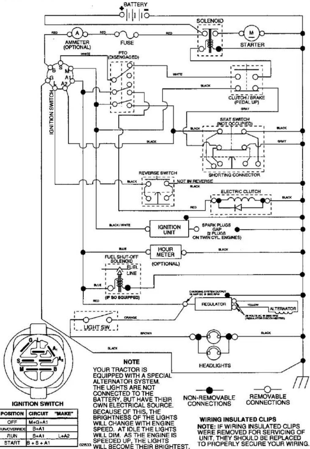
text_image
BATTERY RED AMMETER (OPTIONAL) FUSE SOLENOID M STARTER WHITE PTO (DISENGAGED) WHITE BLACK CLUTCH/BRAKE (PEDAL UP) GRAY SEAT SWITCH (NOT OCCUPIED) BLACK GRAY SHORTING CONNECTOR REVERSE SWITCH NOT IN REVERSE BLACK RED ELECTRIC CLUTCH BLACK IGNITION UNIT SPARK PLUGS GAP (2 PLUGS ON TWIN CYL ENGINES) BLUE HOUR METER (OPTIONAL) BLUE IF SO EQUIPPED) CHARGING SYSTEM OUTPUT IS MAX DC @ 300 RPM REGULATOR YELLOW ALTERNATOR 25 VOLTAC @ 2000 RPM (PENGULATOR DISCONNECTED) ORANGE LIGHT SW BROWN BLACK NOT INLETION SWITCH NOTE YOUR TRACTOR IS EQUIPPED WITH A SPECIAL ALTERNATOR SYSTEM. THE LIGHTS ARE NOT CONNECTED TO THE BATTERY, BUT HAVE THEIR OWN ELECTRICAL SOURCE. BECAUSE OF THIS, THE BRIGHTNESS OF THE LIGHTS WILL CHANGE WITH ENGINE SPEED. AT IDLE THE LIGHTS WILL DIM. AS THE ENGINE IS SPEED UP, THE LIGHTS WILL BECOME THEIR BRIGHTEST. NON-REMOVABLE CONNECTIONS REMOVABLE CONNECTIONS WIRING INSULATED CLIPS NOTE: IF WIRING INSULATED CLIPS WERE REMOVED FOR SERVICING OF UNIT, THEY SHOULD BE REPLACED TO PROPERLY SECURE YOUR WIRING. POSITION CIRCUIT "MAKE" OFF M+G+A1 UN/OVERRIDE B+A1 RUN B+A1 L+A2 START B+S+A1 028333REPAIR PARTS
ELECTRICAL
TRACTOR -- MODEL NUMBER 917.275685
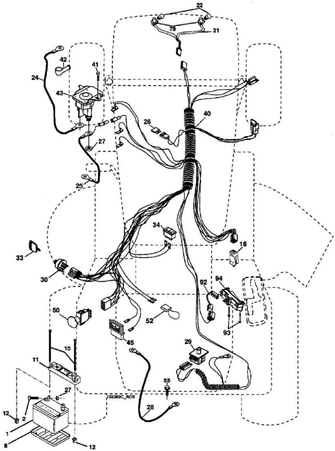
text_image
Technical diagram of an automotive electrical wiring harness with numbered components and wiring connectionsKEY PART
NO. NO. DESCRIPTION
| 1 | 144927 | Battery |
| 2 | 74760412 | Bolt Hex 1/4-20 x 3/4 |
| 8 | 7603J | Tray Battery |
| 10 | 145211 | Bolt Btr Front 1/4-20 x 7-1/2 |
| 11 | 150108 | Holddown Battery Front Mount |
| 12 | 145769 | Nut Push Nylon Battery Front 1/4 |
| 16 | 176138 | Switch Interlock |
| 21 | 175688 | Harness Light |
| 22 | 4152J | Bulb Light |
| 24 | 8860R | Cable Starter |
| 25 | 146148 | Cable Battery |
| 26 | 175158 | Fuse |
| 27 | 73510400 | Nut Keps Hex 1/4-20 unc |
| 28 | 145491 | Cable Ground |
| 29 | 192749 | Switch Seat |
| 30 | 193350 | Switch Ignition |
| 33 | 140403 | Key Molded |
| 34 | 110712X | Switch Light / Reset |
| 40 | 193389 | Harness Ignition |
| 41 | 17720408 | Screw Thd Cut 1/4-20 x 1/2 |
| 42 | 131563 | Cover Terminal |
| 43 | 192507 | Solenoid |
| 45 | 122822X | Ammeter |
| 50 | 174652 | Switch PTO |
| 52 | 141940 | Protection Wire Loop |
| 55 | 17490508 | Screw Thdrol 5/16-18 x 1/2 |
| 79 | 175242 | Socket Asm Bulb Twistlock |
| 92 | 193465 | Harness Pigtail Reverse Switch |
| 93 | 192540 | Screw Plastite 10-14 x 2.0 |
| 94 | 191834 | Module Reverse ROS |
NOTE: All component dimensions given in U.S. inches 1 inch = 25.4 mm
TRACTOR -- MODEL NUMBER 917.275685
CHASSIS AND ENCLOSURES
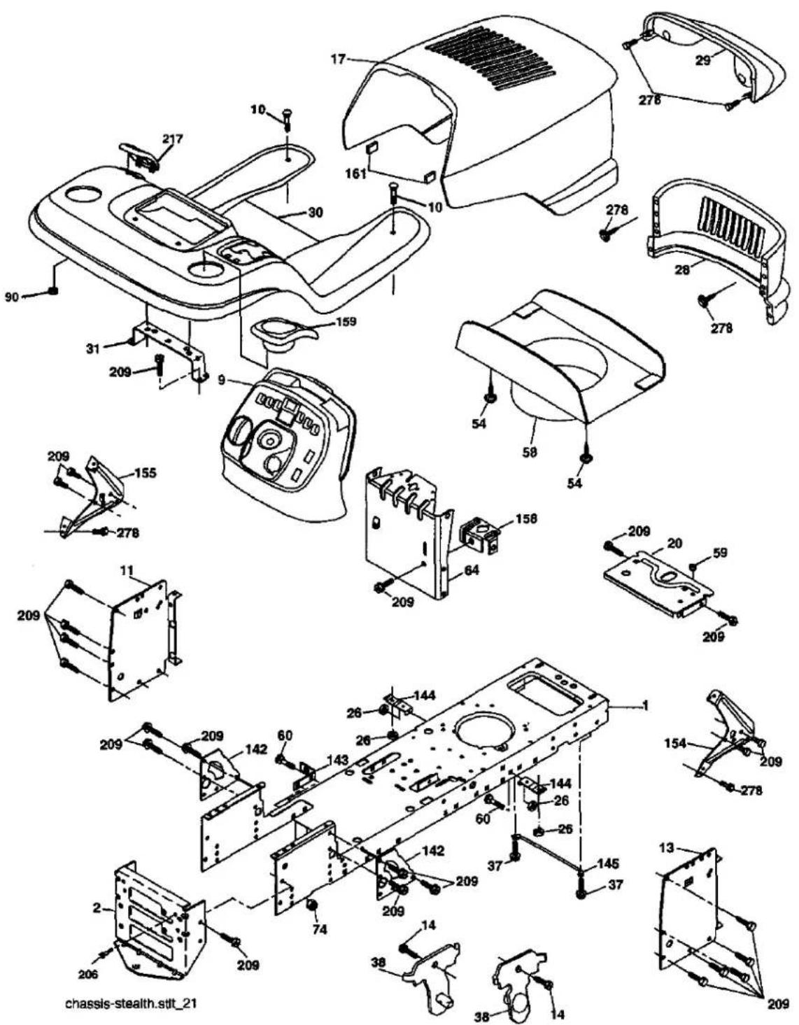
text_image
chassis-stealth.stit_21TRACTOR -- MODEL NUMBER 917.275685
CHASSIS AND ENCLOSURES
KEY PART
NO. NO. DESCRIPTION
| 1 | 174619 | Chassis |
| 2 | 176554 | Drawbar |
| 9 | 193636X428 | Dash |
| 10 | 72140608 | Bolt RDHD SQNK 3/8-16 x 1 |
| 11 | 167203 | Panel Dash LH |
| 13 | 188702X010 | Panel Dash RH |
| 14 | 17490608 | Screw Thdrol 3/8-16 x 1/2 |
| 17 | 175260X428 | Hood Assembly |
| 20 | 162026 | Plate Battery |
| 26 | STD541437 | Locknut Hex with Insert 3/8-16 unc |
| 28 | 174515X428 | Grille |
| 29 | 161840 | Lens Bar |
| 30 | 192395X428 | Fender/Footrest |
| 31 | 139976 | Bracket Fender/Support |
| 37 | 17490508 | Screw Thdrol 5/16-18 x 1/2 TYT |
| 38 | 175710 | Bracket Asm Pivot Mower Rear |
| 54 | 192512 | Screw Hex Wshd 10-32 x 5/8 |
| 58 | 175351 | Duct Hood |
| 59 | 187495 | Bushing 1.375 OD |
| 60 | STD533707 | Bolt Rdhd Sqnk 3/8-16 unc x 3/4 |
| 64 | 174997 | Dash Lower |
| 74 | STD541437 | Nut Crownlock 3/8-16 unc |
| 90 | 124346X | Nut Self-Thd Wsh-Hd 1/4 |
| 142 | 175702 | Plate Reinforcement |
| 143 | 186689 | Bracket Swaybar Chassis |
| 144 | 175582 | Bracket Footrest |
| 145 | 156524 | Rod Pivot Chassis/Hood |
| 154 | 161897 | Bracket Dash Rh |
| 155 | 161900 | Bracket Dash Lh |
| 158 | 162037 | Parking Brake Bkrt |
| 159 | 191120X428 | Cupholder |
| 161 | 164655 | Bumper Extrusion .600 x 3.50 |
| 206 | 170165 | Bolt Shoulder 5/16-18 |
| 209 | 17000612 | Screw Hexwsh Thdr 3/8-16 x 3/4 |
| 217 | 179132X428 | Console Fuel Window |
| 278 | 191611 | Screw 10 x 3/4 Single Lead-Hex |
NOTE: All component dimensions given in U.S. inches 1 inch = 25.4 mm
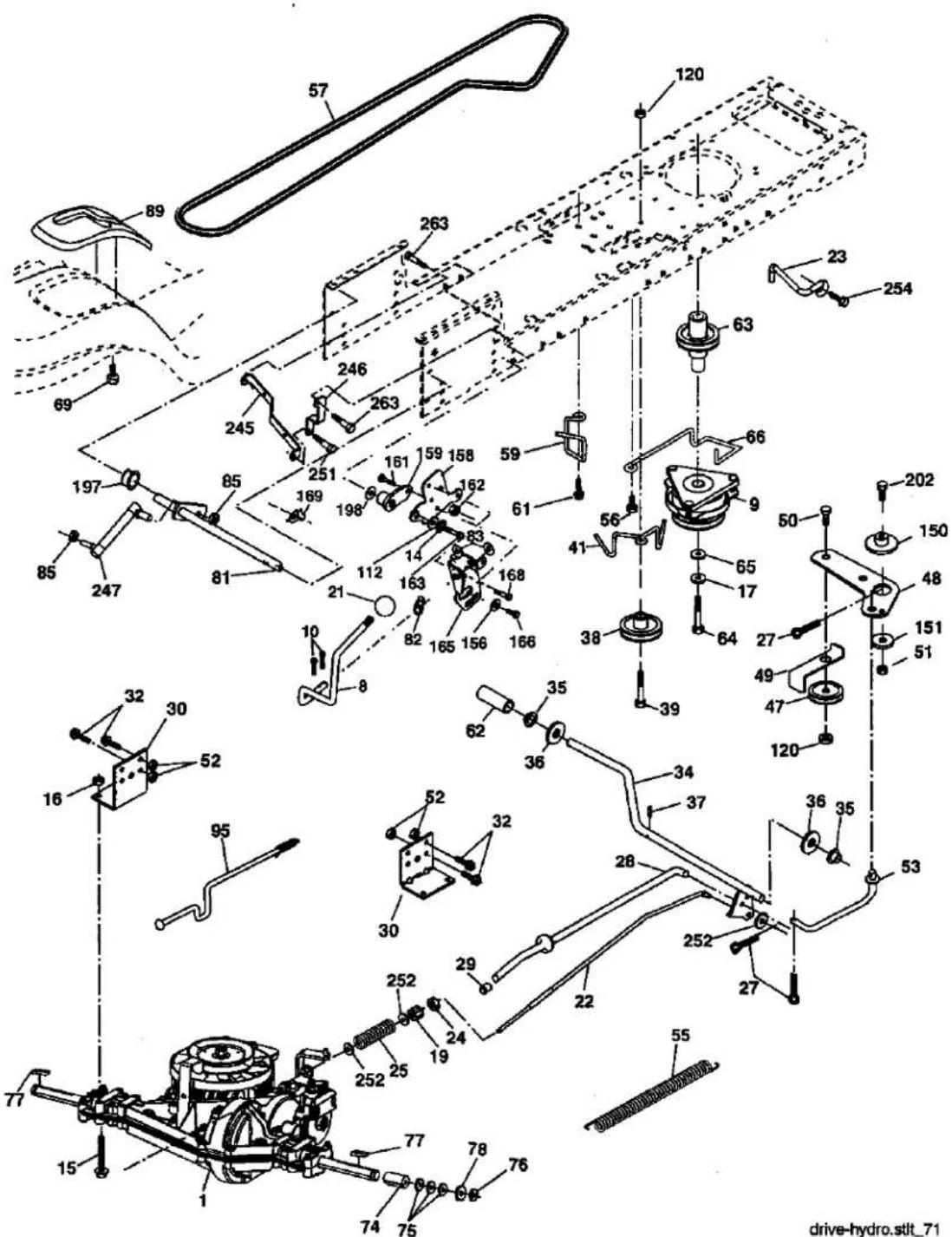
text_image
Technical diagram of a mechanical assembly with numbered components and labeled parts, likely from an engineering or manufacturing context.drive-hydro.stlt_71
TRACTOR -- MODEL NUMBER 917.275685
GROUND DRIVE
| KEYNO. | PARTNO. | DESCRIPTION | KEYNO. | PARTNO. | DESCRIPTION |
| 1 | ---- | Transaxle Peerless LTH2000(See Breakdown) | 64 | 173967 | Bolt Hex 7/16-20 x 4-1/4 Gr. 5 |
| 65 | STD551143 | Washer | |||
| 8 | 192502 | Rod Shift Fender Adjust | 66 | 154778 | Keeper Belt Engine Hydro |
| 9 | 180505 | Clutch | 69 | 142432 | Screw Hex Wsh Hi-Lo 1/4-1/2 unc |
| 10 | STD561210 | Pin Cotter 1/8 x 1 CAD | 74 | 137057 | Spacer |
| 14 | 10040400 | Washer Lock Hvy Helical | 75 | 121749X | Washer 25/32 x 1-1/4 x 16 Ga. |
| 15 | 74490544 | Bolt Hex FLGHD 5/16-18 Gr. 5 | 76 | STD581075 | E-Ring |
| 16 | STD541431 | Nut Lock Hex W/Ins. 5/16-18 unc | 77 | 123583X | Key Square |
| 17 | 126197X | Washer | 78 | 121748X | Washer 25/32 x 1-5/8 x 16 Ga. |
| 1-1/2 OD x 15/32 ID x .250 | 81 | 178139 | Shaft Asm Cross Tapered | ||
| 19 | STD541437 | Nut Lock Hex W/Wsh 3/8-16 unc | 82 | 165711 | Spring Torsion |
| 21 | 106933X | Knob 1/2-13 | 83 | 19171216 | Washer 17/32 x 3/4 x 16 Ga. |
| 22 | 178141 | Rod Brake | 85 | 150360 | Nut Lock Center 1/4-28 FNTHD |
| 23 | 190736 | Bracket Anti-Rotation | 89 | 192387X428 | Console Shift |
| 24 | 73350600 | Nut Hex Jam 3/8-16 unc | 95 | 178134 | Disconnect Asm Rod Bypas LTH |
| 25 | 106888X | Spring, Brake Rod | 112 | 19091210 | Washer 9/32 x 3/4 x 10 Ga. |
| 27 | STD561210 | Pin Cotter 1/8 x 3/4 CAD. | 120 | 73900600 | Nut Lock Flg 3/8-16 |
| 28 | 175765 | Rod Parking Brake | 150 | 175456 | Spacer Retainer |
| 29 | 124236X | Cap Parking Brake | 151 | 19133210 | Washer 13/32 x 2 x 10 Ga. |
| 30 | 169592 | Bracket Transaxle | 156 | 166002 | Washer Srrted 5/16 ID x 1.125 |
| 32 | 74760512 | Bolt Hex Hd 5/16-18 unc x 3/4 | 158 | 165589 | Bracket Shift Mount |
| 34 | 175578 | Shaft Foot Pedal | 159 | 183900 | Hub Shift |
| 35 | 120183X | Bearing Nylon | 161 | 72140406 | Bolt Rdhd Sqnk 1/4-20 x 3/4 Gr. 5 |
| 36 | 19211616 | Washer | 162 | 73680400 | Nut Crownlock 1/4-20 unc |
| 37 | 1572H | Pin Roll | 163 | 74780416 | Bolt Hex Fin 1/4-20 unc x 1 Gr. 5 |
| 38 | 179114 | Pulley Composite | 165 | 165623 | Bracket Pivot Lever |
| 39 | 72110622 | Bolt RDHD | 166 | 17490510 | Screw 5/16-18 x 5/8 |
| 3/8-16 unc x 2-3/4 Gr. 5 | 168 | 165492 | Bolt Shoulder 5/16-18 x .561 | ||
| 41 | 175556 | Keeper Belt Idler | 169 | 165580 | Plate Fastening |
| 47 | 127783 | Pulley Idler V-Groove | 197 | 169613 | Nyliner Snap-In 5/8"ID |
| 48 | 154407 | Bellcrank Clutch | 198 | 169593 | Washer Nyl 7/8 ID x .105" Hyd |
| 49 | 123205X | Retainer Belt | 202 | 72110614 | Bolt Carr Sh 3/8-16 x 1-3/4 Gr. 5 |
| 50 | 72110612 | Bolt Carr Sh 3/8-16 x 1-1/2 Gr. 5 | 245 | 178122 | Strap Torque Lh LTH2000 |
| 51 | STD541437 | Nut Crownlock 3/8-16 unc | 246 | 178121 | Strap Torque Rh LTH2000 |
| 52 | STD541431 | Nut Crownlock 5/16-18 unc | 247 | 181462 | Link Shift Transaxle LTH2000 |
| 53 | 199652 | Link Clutch | 251 | 17060516 | Screw 5/16-18 x 1 |
| 55 | 105709X | Spring Return Clutch | 252 | 19131616 | Washer 13/32 x 1 x 16 Ga. |
| 56 | 17060620 | Screw 3/8-16 x 1-1/4 | 254 | 17000616 | Screw 3/8-16 x 1 |
| 57 | 178138 | V-Belt | 263 | 17000612 | Screw Hex Wsh Thdr 3/8-16 x 3/4 |
| 59 | 169691 | Keeper Center Span | |||
| 61 | 17120614 | Screw 3/8-16 x .875 | |||
| 62 | 123533X | Cover Pedal | NOTE: All component dimensions given in U.S. inches | ||
| 63 | 174607 | Pulley Engine | 1 inch = 25.4 mm | ||
TRACTOR - - MODEL NUMBER 917.275685
STEERING ASSEMBLY
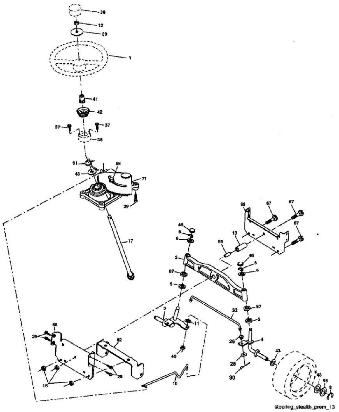
text_image
steering_stealth_prem_13TRACTOR -- MODEL NUMBER 917.275685
STEERING ASSEMBLY
KEY PART
NO. NO. DESCRIPTION
| 1 | 186094X428 | Wheel Steering |
| 2 | 184706 | Axle Asm |
| 3 | 169840 | Spindle Asm LH |
| 4 | 169839 | Spindle Asm RH |
| 5 | 6266H | Bearing Race Thrust Harden |
| 6 | 121748X | Washer 25/32 x 1-5/8 x 16 Ga. |
| 8 | 12000029 | Ring Klip #t5304-75 |
| 10 | 175121 | Link Drag |
| 11 | STD551137 | Washer Lock Hvy Hlcl Spr 3/8 |
| 12 | 73940800 | Nut Hex Jam Toplock 1/2-20 unf |
| 13 | 136518 | Spacer Bearing Axle Front |
| 15 | 145212 | Nut Hex Flange Lock |
| 17 | 177883 | Shaft Asm Steering |
| 26 | 126847X | Bushing Link Drag |
| 28 | 19131416 | Washer 13/32 x 7/8 x 16 Ga. |
| 29 | 17000612 | Screw 3/8-16 x 3/4 |
| 30 | 76020412 | Pin Cotter 1/8 x 3/4 |
| 32 | 192757 | Rod Tie |
| 36 | 155105 | Bushing Strg |
| 37 | 152927 | Screw |
| 38 | 186095X428 | Insert Cap Strg Wh |
| 39 | 19183812 | Washer 9/16 ID x 2-3/8 OD 12 Ga. |
| 40 | 73540600 | Nut Crownlock 3/8-24 |
| 41 | 186737 | Adaptor Wheel Strg |
| 42 | 163888X428 | Boot Steering |
| 43 | 121749X | Washer 25/32 1 1/4 x 16 Ga. |
| 46 | 184946X505 | Cap Spindle |
| 65 | 160367 | Spacer Brace Axle |
| 67 | 72110618 | Bolt Rdhd Sq 3/8-16 unc x 2-1/4 |
| 68 | 169827 | Axle Brace |
| 71 | 175146 | Steering Asm. |
| 82 | 199978 | Bracket Susp. Chassis Front |
| 87 | 173966 | Washer Flat .781 x 1-1/2 x .15 |
| 88 | 175118 | Bolt Shoulder 7/16-20 unc |
| 91 | 175553 | Clip Steering |
| 95 | 188967 | Washer Harden .793 x 1.637 x .060 |
NOTE: All component dimensions given in U.S. inches
1 inch = 25.4 mm
TRACTOR -- MODEL NUMBER 917.275685
ENGINE
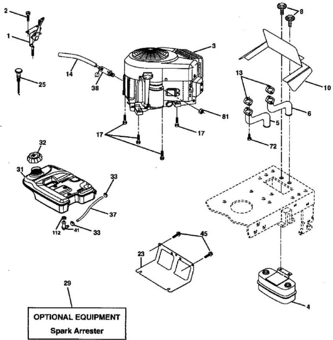
text_image
OPTIONAL EQUIPMENT Spark Arresterengine-bs intek-twin_39
KEY PART
| NO. | NO. | DESCRIPTION |
| 1 | 175437X505 | Control Throttle/Choke |
| 2 | 191611 | Screw 10 x 3/4 Single Lead-Hex |
| 3 | - - - - - - - | Engine B&S Model445677-0413-E1 (See Breakdown) |
| 4 | 149723 | Muffler |
| 5 | 160589 | Exhaust Tube RH |
| 6 | 159955 | Exhaust Tube LH |
| 8 | 171877 | Bolt 5/16-18 unc x 3/4 w/sems |
| 10 | 162797 | Shield Browning |
| 13 | 165391 | Muffler Gasket |
| 14 | 148456 | Tube Drain Oil Easy |
| 17 | 17060624 | Screw 3/8-16 x 1 SMGML-1/2 |
| 23 | 169837 | Shield Heat |
| 25 | 18776X505 | Control Choke |
KEY PART
| NO. | NO. | DESCRIPTION |
| 29 | 137180 | Kit Spark Arrestor (Flat Scrn) |
| 31 | 179022 | Tank Fuel |
| 32 | 179124X428 | Cap Asm Fuel |
| 33 | 123487X | Clamp Hose Black |
| 37 | 8543R | Line Fuel |
| 38 | 181654 | Plug Drain Oil Easy |
| 41 | 139277 | Stem Tank Fuel |
| 45 | 17000612 | Screw Hexwsh Thdr 3/8-16 x 3/4 |
| 72 | 183906 | Screw Socket Head 5/16-18 x 1 |
| 81 | 73510400 | Nut Keps Hex 1/4-20 unc |
| 112 | 3645J | Bushing |
NOTE: All component dimensions given in U.S.
inches 1 inch = 25.4 mm
To avoid should b days or l the engir and carb Use fres Instructic Never us products damage
TO STA
When sta or if the e take extr the tank
-
Be su transi
-
Sit or depre parkir
-
Place (N) p
-
Move positi
-
Move
-
Pull c start attem need
NOTE: B cold star
- Insert clock key a not run than 1 engine attempt a few still do trol or
WARM V above)
- When contr run si run ro slight contrir
TRACTOR -- MODEL NUMBER 917.275685
SEAT ASSEMBLY
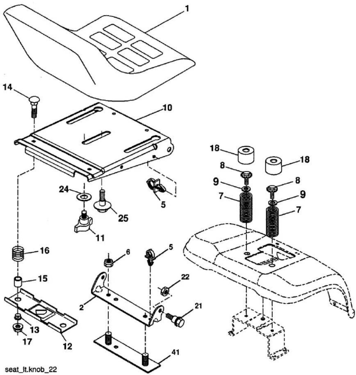
text_image
1 14 10 24 25 11 16 15 13 17 12 18 8 9 7 18 8 9 7 22 21 41 seat_lt.knob_22KEY PART
| NO. | NO. | DESCRIPTION |
| 1 | 180598 | Seat |
| 2 | 180166 | Bracket Pivot Fender |
| 5 | 145006 | Clip Push-In |
| 6 | STD541437 | Nut Hex w/Ins 3/8-16 unc |
| 7 | 124181X | Spring Seat Cprsn |
| 8 | 17000616 | Screw 3/8-16 x 1-1/2 |
| 9 | 19131614 | Washer 13/32 x 1 x 14 Ga. |
| 10 | 195696 | Pan Seat |
| 11 | 166369 | Knob Seat Adj Wingnut |
| 12 | 174648 | Bracket Mounting Switch |
| 13 | 121248X | Bushing Snap Blk Nyl 50 Id |
| 14 | 72050412 | Bolt Rdhd Sqnk 1/4-20 x 1-1/2 |
KEY PART
| NO. | NO. | DESCRIPTION |
| 15 | 121249X | Spacer Split |
| 16 | 123740X | Spring Cprsn |
| 17 | 123976X | Nut Lock 1/4 Lge Flg Gr. 5 Zinc |
| 18 | 124238X | Cap Spring Seat |
| 21 | 171852 | Bolt Shoulder 5/16-18 unc |
| 22 | STD541431 | Nut Hex Lock W/Ins 5/16-18 |
| 24 | 19171912 | Washer 17/32 x 1-3/16 x 12 Ga. |
| 25 | 127018X | Bolt Shoulder 5/16-18 x 62 |
| 41 | 140675 | Strap Asm. Fender |
| NOTE: All component dimensions given in U.S. inches1 inch = 25.4 mm | ||
TRACTOR - - MODEL NUMBER 917.275685
DECALS
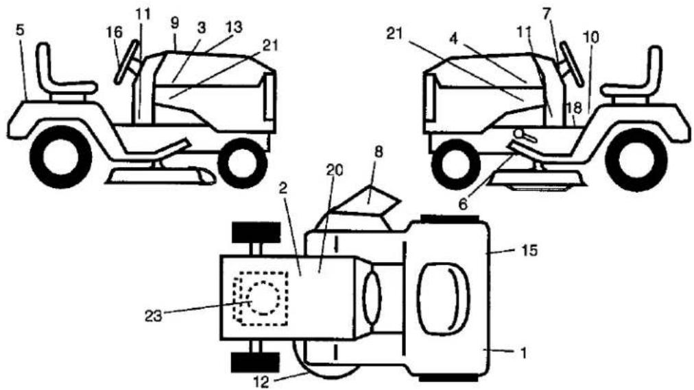
text_image
Technical diagram of three automotive components with numbered parts, likely an industrial or agricultural device assembly.KEY PART NO. NO.
| 1 | 187407 | Decal Reflector LH |
| 2 | 138047 | Decal Battery Diehard Sears |
| 3 | 194023 | Decal Hood RH |
| 4 | 194024 | Decal Hood LH |
| 5 | 194027 | Decal Fender Craftsman |
| 6 | 146046 | Decal V-Belt Drive Schematic |
| 7 | 193654 | Decal Dash |
| 8 | 179128 | Decal Deck Caution |
| 9 | 400482 | Decal Replacement Hood |
| 10 | 156439 | Decal Fender Danger |
| 11 | 189637 | Decal Panel Dash |
| 12 | 160396 | Decal V-Belt Schematic |
KEY PART NO. NO.
| 13 | 133644 | Decal Replacement Parts |
| 15 | 187408 | Decal Reflector RH |
| 16 | 164065 | Decal Steering Wheel |
| 18 | 193307 | Decal Fender Opr. |
| 20 | 149516 | Decal Battery |
| 21 | 194025 | Decal Hood Side Panel |
| 23 | 189684 | Decal Engine |
| -- | 178392 | Decal Chassis Disconnect |
| -- | 184310X428 | Pad Footrest LH |
| -- | 184311X428 | Pad Footrest RH |
| -- | 400445 | Manual Owner's English |
| -- | 400446 | Manual Owner's Spanish |
WHEELS & TIRES
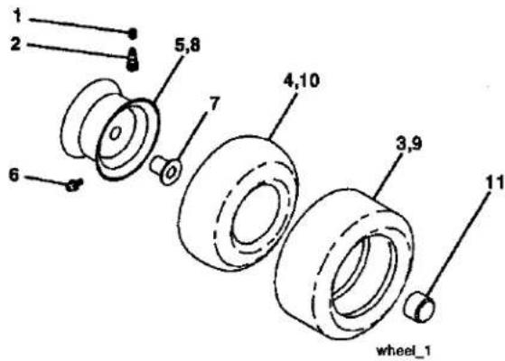
text_image
1 2 5,8 7 4,10 6 3,9 11 wheel_1KEY PART NO. NO.
| 1 | 59192 | Cap Valve Tire |
| 2 | 65139 | Stem Valve |
| 3 | 106222X | Tire F Ts 15 x 6.0 - 6 Service |
| 4 | 59904 | Tube Front (Service Item Only) |
| 5 | 106732X417 | Rim Asm 6" front Service |
| 6 | 278H | Fitting Grease (Front Wheel Only) |
| 7 | 9040H | Bearing Flange (Front Wheel Only) |
| 8 | 106108X417 | Rim Asm 8" rear Service |
| 9 | 138468 | Tire R Ts 20 x 8-8 C Service |
| 10 | 7152J | Tube Rear (Service Item Only) |
| 11 | 104757X428 | Cap Axle Blk 1.50 x 1.00 |
| -- | 144334 | Sealant, Tire (10 oz. Tube) |
NOTE: All component dimensions given in U.S. inches 1 inch = 25.4 mm
TRACTOR -- MODEL NUMBER 917.275685
LIFT ASSEMBLY
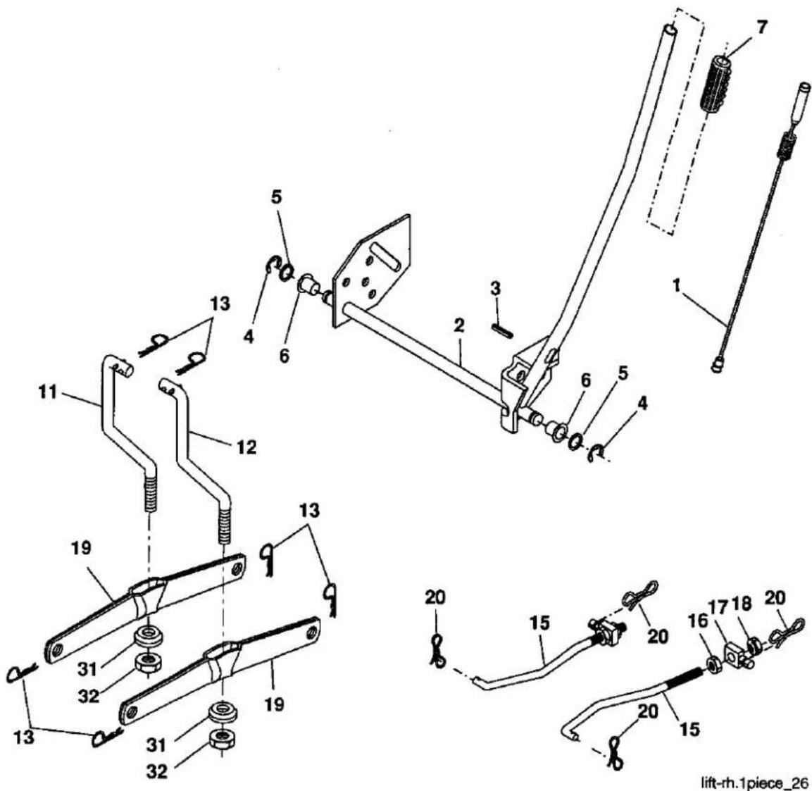
text_image
Technical diagram of a mechanical linkage assembly with numbered components and assembly detailsKEY PART
| NO. | NO. | DESCRIPTION |
| 1 | 197980 | Plunger Assembly |
| 2 | 198070 | Shaft Assembly, Lift |
| 3 | 188822 | Pin Groove |
| 4 | 12000002 | E-Ring |
| 5 | 19211621 | Washer 21/32 x 1 x 21 Ga. |
| 6 | 120183X | Bearing Nylon |
| 7 | 175830 | Grip Handle Fluted |
| 11 | 139865 | Link Lift L.H. |
| 12 | 139866 | Link Lift R.H. |
| 13 | STD624008 | Retainer Spring |
| 15 | 173288 | Link Front Susp |
KEY PART
| NO. | NO. | DESCRIPTION |
| 16 | 73350800 | Nut Hex Jam 1/2-13 unc |
| 17 | 175689 | Trunnion Front Susp |
| 18 | 73800800 | Nut Lock w/Wsh 1/2-13 unc |
| 19 | 139868 | Arm Asm Suspension Mower |
| 20 | 194209 | Pin Cotter 7/16 Bow Tie Lock |
| 31 | 169865 | Bearing Pivot Lift |
| 32 | 73540600 | Nut Crownlock 3/8-24 |
NOTE: All component dimensions given in U.S. inches 1 inch = 25.4 mm
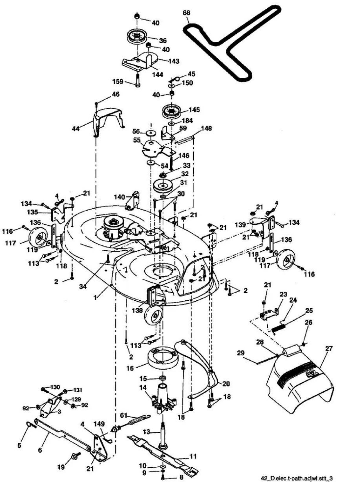
text_image
Technical diagram of a mechanical assembly with numbered components and labeled parts, likely from an electronics or industrial machine.42_D.elec.t-path.adjwl.stit_3
TRACTOR -- MODEL NUMBER 917.275685
MOWER DECK
| KEYNO. | PARTNO. | DESCRIPTION | KEYNO. | PARTNO. | DESCRIPTION |
| 1 | 182032 | Mower Housing | 56 | 165723 | Spacer Retainer |
| 2 | STD533107 | Bolt | 59 | 141043 | Guard Tuv Idler (94) |
| 3 | 138017 | Bracket Asm Sway Bar Front | 61 | 174882 | Spring Ext Elect Clutch |
| 4 | 194208 | Pin Cotter 5/16 Bow Tie Lock | 68 | 174883 | V-Belt |
| 5 | STD624008 | Retainer Spring | 92 | STD541437 | Locknut Hex W/Wsh 3/8-16 unc |
| 6 | 178024 | Bar Sway Deck | 113 | 17000510 | Screw 5/16-18 |
| 8 | 850857 | Bolt Hex 3/8-24 x 1.25 Gr. 8 | 116 | 4898H | Bolt Shoulder |
| 9 | STD551137 | Washer Lock | 117 | 188606 | Wheel Gauge |
| 10 | 140296 | Washer Hardened(The following blades are available) | 118 | 73930600 | Nut Crownlock 3/8-1 |
| Blade 42" Hi-Lift(For bagging or discharge) | 119 | 19121414 | Washer 13/32 x 7/8 x 14 Ga. | ||
| 11 | 138971 | Blade 42" Mulching STD(For mulching mowers only) | 129 | 19131312 | Washer 13/32 x 13/16 x 12 Ga. |
| 130 | STD523710 | Bolt Fin Hex 3/8-16 unc x 1Gr. 5 | |||
| -- | 134149 | Blade 42" Mulching Premium(For better wear when mulching) | 131 | STD533710 | Bolt Rdhd Sqnk 3/8-16 unc x 1 |
| 134 | 156941 | Pin Head Rivet | |||
| -- | 139775 | Blade 42" Mulching Premium(For better wear when mulching) | 135 | 159765 | Bracket Asm Wheel Gauge Rear LH |
| 13 | 137645 | Shaft Assembly Mandrel Vented(Incl. Key Number 6) | 136 | 155986 | Bar Adjusting Gauge Wheel |
| 138 | 159763 | Bracket Asm Wheel Gauge Rear RH | |||
| 14 | 128774 | Housing Mandrel Vented | |||
| 15 | 110485X | Bearing Ball Mandrel | 139 | 159767 | Bracket Asm Wheel Gauge Front RH |
| 16 | 174493 | Stripper Mower Deck | |||
| 18 | 72140505 | Bolt Carriage 5/16-18 x 5/8 | 140 | 159768 | Bracket Asm Wheel Gauge Front LH |
| 19 | 132827 | Bolt Shoulder | |||
| 20 | 159770 | Baffle Vortex | 143 | 157109 | Bracket Arm Idler 42" |
| 21 | STD541431 | Nut Crownlock 5/16-18 unc | 144 | 158634 | Keeper Belt 42" Clutch Cable |
| 23 | 177563 | Bracket Deflector | 145 | 165888 | Pulley Idler Flat |
| 24 | 105304X | Cap Sleeve | 146 | 171977 | Bolt Carraige Idler |
| 25 | 123713X | Spring Torsion Deflector | 148 | 169022 | Spring Return Idler |
| 26 | 110452X | Nut Push | 149 | 165898 | Retainer Spring Yellow Zinc |
| 27 | 130968X428 | Shield Deflector | 150 | 19091210 | Washer 9/32 x 3/4 x 10 Ga. |
| 28 | 19111016 | Washer 11/32 x 5/8 x 16 Ga. | 159 | STD533717 | Bolt Rdhd Sqn 3/8-16 unc x 1-3/4 |
| 29 | 131491 | Rod Hinge | 184 | 19131410 | Washer 3/8 |
| 30 | 173984 | Screw Thdrol Rolling Wsh Hd | -- | 130794 | Mandrel Assembly (Includes housing, shaft and shaft hardware only-pulley not included) |
| 31 | 187690 | Washer Spacer | |||
| 32 | 153535 | Pulley Mandrel | |||
| 33 | 178342 | Nut Toplock Flanged | -- | 181542 | Replacement Mower, Complete (Std. Deck-Order separately gauge wheels 5, 116-119, 134, 136). |
| 34 | STD533717 | Bolt | |||
| 36 | 131494 | Pulley Idler Flat | |||
| 40 | 73900600 | Nut Lock 3/8-16 unc | |||
| 44 | 140088 | Guard Mandrel L.H. | |||
| 45 | STD624003 | Retainer | |||
| 46 | 137729 | Screw Thd. Roll 1/4-20 x 5/8 | NOTE: All component dimensions given in U.S.inches | ||
| 54 | 178515 | Washer Hardened | 1 inch = 25.4 mm | ||
| 55 | 155046 | Arm idler | |||
TRACTOR -- MODEL NUMBER 917.275685
PEERLESS TRANSAXLE -- MODEL NUMBER LTH2000
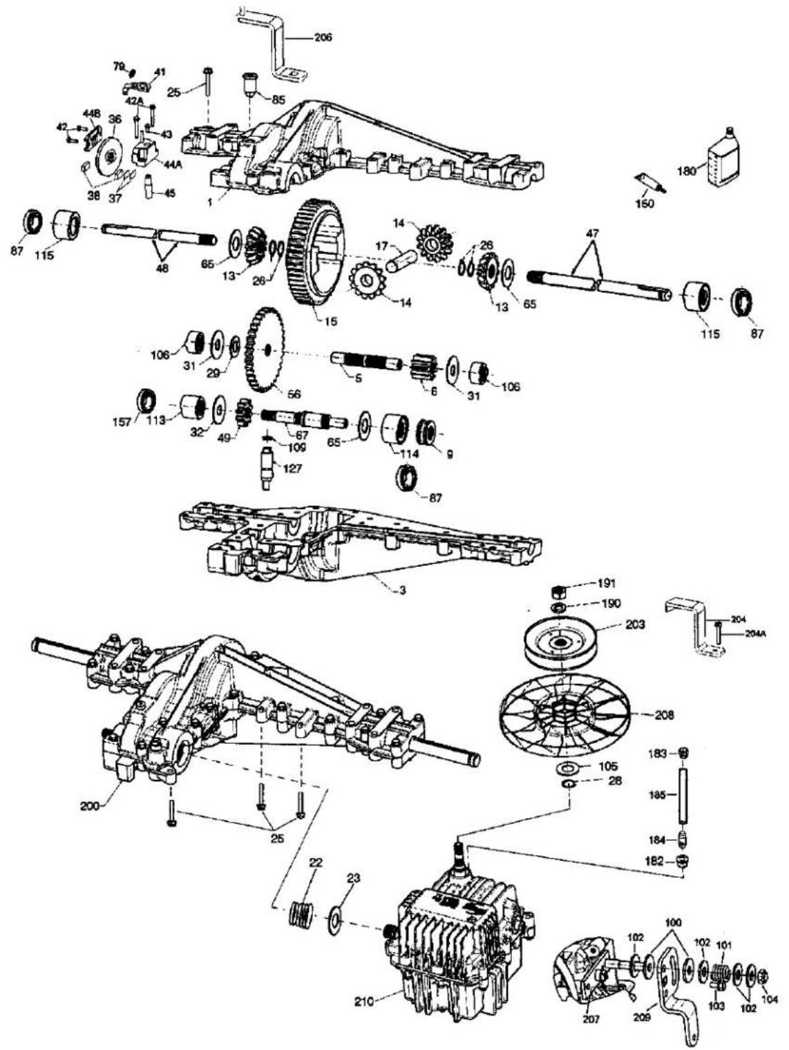
text_image
Technical diagram of a mechanical assembly with numbered components and exploded viewsTRACTOR -- MODEL NUMBER 917.275685
PEERLESS TRANSAXLE -- MODEL NUMBER LTH2000
| KEY NO. | PART NO. | DESCRIPTION | KEY NO. | PART NO. | DESCRIPTION |
| 1 | 772151 | Cover L.H. | 70 | 786196 | Spacer .625 .765 |
| 3 | 770135 | Case | 79 | 792201 | Spring |
| 5 | 776355 | Counter Shaft | 85 | 792154 | Oil Fill Plug |
| 6 | 778263 | Spur Gear 11T | 87 | 788088A | Oil Seal 3/4" |
| 9 | 786197 | Neutral Sleeve (.572) | 99 | 792141 | Washer .377ID .058W |
| 13 | 778368 | Bevel Gear (Incl. 14) (13 Teeth) | 100 | 792200 | Snubber Washer |
| 101 | 792199 | Snubber Spring .47ID | |||
| 14 | 778368 | Bevel Gear (Incl. 13) (13 Teeth) | 102 | 792184 | Washer .437ID .078W |
| 103 | 792193 | Screw, 1/4-28 x .490 | |||
| 15 | 778373 | Ring Gear (54 Teeth) | 104 | 792198 | Nut, 3/8-24 |
| 17 | 786139 | Drive Pin | 105 | 780096 | Washer .625 ID .057W |
| 22 | 792194 | Spring | 106 | 786162 | Sleeve Assembly |
| 23 | 792195 | Washer .750 ID | 107 | 792046 | Screw, 1/4-20 x 1" |
| 25 | 792073A | Screw 1/4-20 x 1-1/4" | 109 | 788104 | "O" Ring |
| 26 | 792125 | Retaining Ring | 113 | 786199 | Sleeve Ass'y (Incl. 157) |
| 28 | 792035 | Retaining Ring | 114 | 786200 | Sleeve Ass'y (Incl. 87) |
| 29 | 780065 | Washer .627 ID .091W | 115 | 786198 | Sleeve Assembly (Incl. 87) |
| 31 | 780189 | Washer .563 ID .062W | 127 | 784384 | Shift Lever Ass'y (Incl. 109) |
| 36 | 790071 | Brake Disk | 150 | 788093A | Liquid Gasket RTV Silicon |
| 37 | 790007 | Brake Pad Plate | 157 | 788102 | Oil Seal 9/16"ID |
| 38 | 799021 | Brake Pad | 180 | 730229 | BOil Spec. (80W90) |
| 40 | 792204 | Roll Pin .25 | 182 | 788103 | Grommet |
| 41 | 790102 | Brake Lever | 183 | 792118 | Relief Valve |
| 42 | 792202 | Screw, 1/4-20 x 3/4 | 184 | 792196 | Hose Barb |
| 42A | 792203 | Screw, 1/4-20 x 1-3/4 | 185 | 798050 | Tubing 1/2 x 5 |
| 43 | 792171 | Screw, 10-24 x .500 | 190 | 792150 | Washer |
| 44A | 790100 | Inside Brake (Mach) | 191 | 792151 | Nut 7/16-20 |
| 44B | 790099 | Outside Brake (Casting) | 200 | 794787 | Differential (Gear Reduction Drive) |
| 45 | 790101 | Actuator Rod | |||
| 47 | 774869 | Axle 16.812 | 203 | 798044 | Pulley & Hub Ass'y |
| 48 | 774688 | Axle 11.625 | 206 | 798055 | Disconnect Lever |
| 49 | 778378 | Spur Gear 18T | 207 | 798053 | Mounting Plate |
| 56 | 778379 | Spur Gear 81T | 208 | 798040 | Fan |
| 65 | 780195 | Washer .750ID .062W | 209 | 798054 | Control Lever |
| 67 | 776440 | Brakeshaft | 210 | 794788 | Hydro Module LH Fender |
TRACTOR -- MODEL NUMBER 917.275685
BRIGGS ENGINE-MODEL NUMBER 445677 TYPE NUMBER 0413-E1
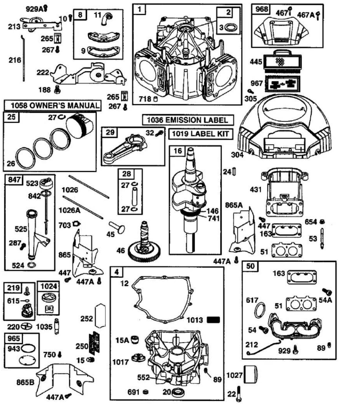
text_image
929A 213 265 267 8 11 9 216 222 188 1058 OWNER'S MANUAL 25 27 26 1036 EMISSION LABEL 1 2 3 968 467 467A 445 967 305 265 267 29 32 1019 LABEL KIT 16 304 847 523 842 1026 1026A 703 525 287 524 865 447 447A 45 46 447A 146 741 865A 447 163 53 51 50 163 617 51 54A 965 943 750 250 15 865B 447A 4 12 1013 15A 1017 552 89 691 20 1027 22TRACTOR -- MODEL NUMBER 917.275685
BRIGGS ENGINE-MODEL NUMBER 445677 TYPE NUMBER 0413-E1
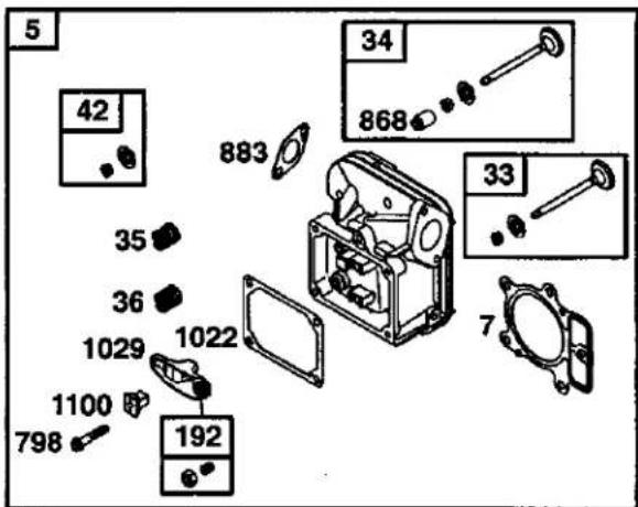
text_image
5 42 883 34 868 33 7 35 36 1029 1022 1100 798 192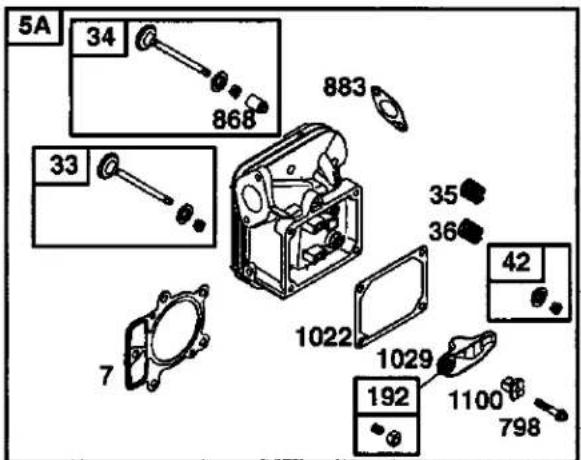
text_image
5A 34 868 883 33 35 36 42 1022 1029 192 1100 798 7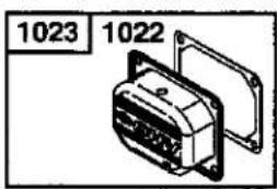
text_image
1023 1022914
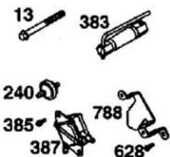
text_image
13 383 240 385 387 788 628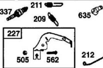
text_image
337 211 209 635 227 505 562 212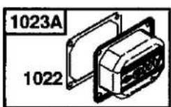
914
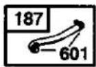
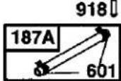
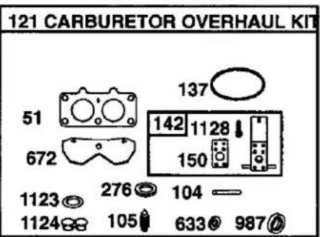
text_image
121 CARBURETOR OVERHAUL KIT 51 672 137 142 1128 150 1123 276 104 1124 105 633 987
text_image
977 CARBURETOR GASKET SET 51 137 276 672 150 987 1123 1124 633

text_image
125 163 141 231 108 633 98 142 1128 150 131 130 95 987 133 104 975 137 1127 276 947 276 105 135 1124 1126 1123 160 117A 51 1353 1342 117ATRACTOR -- MODEL NUMBER 917.275685
BRIGGS ENGINE-MODEL NUMBER 445677 TYPE NUMBER 0413-E1
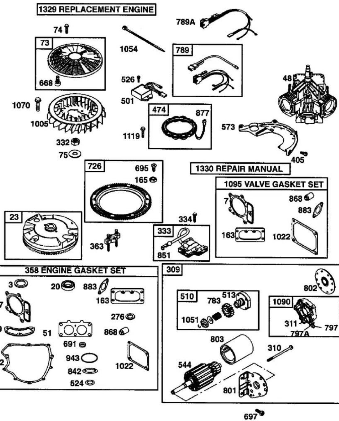
text_image
1329 REPLACEMENT ENGINE 74 73 668 1070 1005 332 75 1054 526 501 1119 474 877 573 405 726 695 165 1330 REPAIR MANUAL 1095 VALVE GASKET SET 7 868 883 163 1022 23 363 333 851 358 ENGINE GASKET SET 3 20 883 163 276 51 691 868 943 1022 309 510 783 513 1051 803 544 801 310 802 1090 311 797A 697TRACTOR -- MODEL NUMBER 917.275685
BRIGGS ENGINE-MODEL NUMBER 445677 TYPE NUMBER 0413-E1
| KEYNO. | PARTNO. | DESCRIPTION | KEYNO. | PARTNO. | DESCRIPTION |
| 1 | 699753 | Cylinder Assembly | 150 | 690995 ‡ | Gasket-Nozzle |
| 2 | 499585 | Kit-Bushing/Seal (Magneto Side) | 160 | 699727 | Retainer-Solenoid |
| 3 | 391086• | Seal-Oil (Magneto Side) | 163 | 691001•+ | Gasket-Air Cleaner |
| 4 | 699747 | Sump-Engine | 165 | 693148 | Nut (Ring Gear) |
| 5 | 693998 | Head-Cylinder (Cylinder 1) | 187 | 691049 | Line-Fuel |
| 5A | 693999 | Head-Cylinder (Cylinder 2) | 187A | 691050 | Line-Fuel (Cut to Required Length) |
| 7 | 693997•+ | Gasket-Cylinder Head | |||
| 8 | 499601 | Breather Assembly | 188 | 691108 | Screw (Control Bracket) |
| 9 | 690937• | Gasket-Breather | 192 | 690083 | Adjuster-Rocker Arm |
| 10 | 691108 | Screw (Breather Assembly) | 209 | 697674 | Spring-Governor |
| 11 | 690942 | Tube-Breather | 211 | 691019 | Spring-Governed Idle |
| 12 | 697227• | Gasket-Crankcase | 212 | 695238 | Link-Governor |
| 13 | 791130 | Screw (Cylinder Head) | 213 | 691021 | Bracket-Choke Control |
| 15 | 690946 | Plug-Oil Drain | 216 | 691022 | Link-Choke |
| 15A | 691680 | Plug-Oil Drain | 219 | 698231 | Gear-Governor |
| 16 | 790136 | Crankshaft | 220 | 690412 | Washer (Governor Gear) |
| 20 | 690947• | Seal-Oil (PTO Side) | 222 | 698761 | Bracket-Control |
| 22 | 694966 | Screw (Crankcase Cover) | 227 | 691048 | Lever-Governor Control |
| 23 | 691053 | Flywheel | 231 | 690718 | Screw (Choke Valve) |
| 24 | 222698 | Key-Flywheel | 240 | 691035 | Filter-Fuel |
| 25 | 694003 | Piston Assembly (Standard) | 250 | 690957 | Retainer-Breather |
| 694007 | Piston Assembly (.020" Oversize) | 252 | 690956 | Collector-Oil | |
| 26 | 694004 | Ring Set (Standard) | 265 | 691024 | Clamp-Casing |
| 694008 | Ring Set (.020" Oversize) | 267 | 695134 | Screw (Casing Clamp) | |
| 27 | 690975 | Lock-Piston Pin | 276 | 690997• ‡ | Washer-Sealing |
| 28 | 690229 | Pin-Piston (Standard) | 287 | 691108 | Screw (Dipstick/Tube Assembly) |
| 29 | 499583 | Rod-Connecting (Standard) | 304 | 790688 | Housing-Blower |
| 32 | 690976 | Screw (Connecting Rod) | 305 | 691005 | Screw (Blower Housing) |
| 33 | 499596 | Valve-Exhaust | 305A | 790690 | Screw (Blower Housing) |
| 34 | 697464 | Valve-Intake | 309 | 691262 | Motor-Starter |
| 35 | 690963 | Spring-Valve (Intake) | 310 | 691263 | Screw (Starter Motor) |
| 36 | 690963 | Spring-Valve (Exhaust) | 311 | 497608 | Brush Set |
| 42 | 499586 | Keeper-Valve | 332 | 691059 | Nut (Flywheel) |
| 45 | 690977 | Tappet-Valve | 333 | 691060 | Armature-Magneto |
| 46 | 790562 | Camshaft | 334 | 691061 | Screw (Magneto Armature) |
| 48 | 698172 | Short Block | 337 | 691043 | Spark Plug |
| 50 | 695241 | Manifold-Intake | 358 | 694012 | Gasket Set-Engine |
| 51 | 690950• ‡ | Gasket-Intake | 363 | 691062 | Puller-Flywheel |
| 53 | 690951 | Stud (Carburetor) | 383 | 690966 | Wrench-Spark Plug |
| 54 | 695239 | Screw (Intake Manifold) | 385 | 690960 | Screw (Fuel Pump) |
| 54A | 699816 | Screw (Intake Manifold) | 387 | 808656 | Pump-Fuel |
| 73 | 494439 | Screen-Rotating | 404 | 690442 | Washer (Governor Crank) |
| 74 | 698425 | Screw (Rotating Screen) | 405 | 697820 | Screw (Back Plate) |
| 75 | 691056 | Washer (Flywheel) | 418 | 690999 | Plate-Carburetor |
| 89 | 690283 | Plug-Oil | 431 | 790816 | Elbow-Intake |
| 95 | 690718 | Screw (Throttle Valve) | 445 | 499486 | Filter-Air Cleaner Cartridge |
| 98 | 699721 | Kit-Idle Speed | 447 | 691003 | Screw (Air Guide Cover) |
| 104 | 694918∅ | Pin-Float Hinge | 447A | 691108 | Screw (Air Guide Cover) |
| 105 | 698537∅ | Valve-Float Needle | 467 | 691008 | Knob-Air Cleaner |
| 108 | 699723 | Valve-Choke | 467A | 790697 | Knob-Air Cleaner |
| 117 | 699494 | Jet-Main (Standard) | 474 | 696458 | Alternator |
| 117A | 699495 | Jet-Main (Standard) | 501 | 691185 | Regulator |
| 121 | 699734 | Kit-Carburetor Overhaul | 505 | 691029 | Nut (Governor Control Lever) |
| 125 | 699709 | Carburetor | 510 | 497606 | Drive-Starter |
| 130 | 690993 | Valve-Throttle | 513 | 692024 | Clutch-Drive |
| 131 | 499805 | Kit-Throttle Shaft | |||
| 133 | 699724 | Float-Carburetor | Included in Engine Gasket Set, Key. No. 358 | ||
| 135 | 699729 | Tube-Fuel Transfer | ∅ | Included in Carburetor Overhaul Kit,Key.No.121 | |
| 137 | 690994∅‡ | Gasket-Float Bowl | Included in Carburetor Gasket Set, Key. No.977 | ||
| 146 | 690979 | Key-Timing | Included in Valve Overhaul Kit, Key. No. 1095 | ||
NOTE: All component dimensions given in U.S. inches 1 inch = 25.4 mm
TRACTOR -- MODEL NUMBER 917.275685
BRIGGS ENGINE-MODEL NUMBER 445677 TYPE NUMBER 0413-E1
| KEYNO. | PARTNO. | DESCRIPTION | KEYNO. | PARTNO. | DESCRIPTION |
| 523 | 691036 | Dipstick | 967 | 273638 | Filter-Pre Cleaner |
| 524 | 691032• | Seal-O Ring (Dipstick Tube) | 968 | 790689 | Cover-Air Cleaner |
| 525 | 691037 | Tube-Dipstick | 975 | 499810 | Bowl-Float |
| 526 | 691108 | Screw (Regulator) | 977 | 699735 | Gasket Set-Carburetor |
| 544 | Armature-Starter (Serviced by 691262 Starter Motor Only) | 987 | 691000 ∅‡ | Seal-Throttle Shaft | |
| 552 | 690552 | Bushing-Governor Crank | 1005 | 790698 | Fan-Flywheel |
| 552A | 690553 | Bushing-Governor Crank | 1013 | 690954 | Nipple-Oil Filter |
| 562 | 690311 | Bolt (Governor Control Lever) | 1017 | 690770 | Screen-Oil Pump |
| 573 | 691009 | Plate-Back | 1019 | 693995 | Kit-Label |
| 601 | 691038 | Clamp-Hose | 1022 | 690971 •+ | Gasket-Rocker Cover |
| 615 | 698290 | Retainer-Governor Shaft | 1023A | 499600 | Cover-Rocker Arm (Cylinder 1) |
| 616 | 691045 | Crank-Governor | 1024 | 499054 | Cover-Rocker Arm (Cylinder 2) |
| 617 | 697891 | Seal-O Ring (Intake Manifold) | 1026 | 690981 | Pump-Oil |
| 628 | 690960 | Screw (Fuel Pump Bracket) | 1026A | 690982 | Rod-Push (Steel) |
| 633 | 690998 ∅‡ | Seal-Choke/Throttle Shaft | 1027 | 492932 | Rod-Push (Aluminum) |
| 635 | 66538 | Boot-Sparkplug | 1029 | 690972 | Filter-Oil |
| 654 | 690958 | Nut (Carburetor) | 1035 | 691042 | Arm-Rocker |
| 668 | 691215 | Spacer | 1036 | 790625 | Shaft-Pump |
| 672 | 690234 ∅‡ | Gasket-Carburetor Plate | 1051 | 691265 | Label-Emission |
| 691 | 690657• | Seal-Governor Shaft | 1054 | 280275 | Ring-Retaining |
| 695 | 693149 | Screw (Ring Gear) | 1058 | 275475 | Cable-Tie |
| 697 | 690372 | Screw (Drive Cap) | 1070 | 690372 | Owner's Manual |
| 703 | 691010 | Clip | 1090 | 691293 | Screw (Flywheel Fan) |
| 718 | 690959 | Pin-Locating | 1095 | 694013 | Retainer-Brush |
| 726 | 499612 | Gear-Ring | 1100 | 690973 | Set-Valve Gasket |
| 741 | 690980 | Gear-Timing | 1119 | 691183 | Pivot-Rocker Arm |
| 742 | 690328 | Retainer-E Ring | 1123 | 699725 | Screw (Alternator) |
| 750 | 696999 | Screw (Oil Pump Cover) | 1124 | 690988 ∅‡ | Seal-O Ring (Solenoid Retainer) |
| 783 | 693058 | Gear-Pinion | 1126 | 690991 | Seal-O Ring (Fuel Transfer Tube) |
| 788 | 691039 | Bracket-Fuel Pump | 1128 | 690990 ∅ | Screw (Fuel Transfer Tube) |
| 789 | 698330 | Harness-Wiring | 1329 | 445777-0027 | Screw (Carburetor Nozzle) |
| 789A | 696576 | Harness-Wiring | Replacement Engine (If original engine is equipped with a six pin wiring harness transfer to the replacement engine. | ||
| 797 | 691029 | Nut (Brush Retainer) | Transfer muffler and/or spark arrestor assembly from the original engine if suitable for additional service or add new parts as required. Transfer oil sensor to the replacement engine). | ||
| 797A | 693167 | Nut (Brush Retainer) | |||
| 798 | 697890 | Screw (Rocker Arm) | |||
| 801 | 691283 | Cap-Drive | |||
| 802 | 691286 | Cap-End | |||
| 803 | Housing-Starter (Serviced by 691262 Starter Motor Only) | ||||
| 842 | 691031• | Seal-O Ring (Dipstick) | |||
| 847 | 499602 | Assembly-Dipstick/Tube | |||
| 851 | 493880 | Terminal-Spark Plug | 1330 | 273521 | Repair Manual |
| 855 | 691011 | Adapter-Air Cleaner | 1342 | 699731 | Extension-Fuel Transfer Tube |
| 865 | 691012 | Cover-Air Guide (Cylinder 1) | 1353 | 699725 | Seal-O Ring (Fuel Transfer Tube Extension) |
| 865A | 691014 | Cover-Air Guide (Cylinder 2) | |||
| 865B | 691015 | Cover-Air Guide | |||
| 868 | 690968 •+ | Seal-Valve | • | Included in Engine Gasket Set, Key. No. 358 | |
| 877 | 399916 | Wire/Connector-Alternator | ∅ | Included in Carburetor Overhaul Kit, Key. No. 121 | |
| 883 | 690970 •+ | Gasket-Exhaust | |||
| 914 | 691127 | Screw (Rocker Arm Cover) | ‡ | Included in Carburetor Gasket Set, Key. No.977 | |
| 918 | 694000 | Hose-Vacuum | + | Included in Valve Overhaul Kit, Key. No. 1095 | |
| 929 | 695239 | Screw (Choke Control Bracket) | |||
| 929A | 691003 | Screw (Choke Control Bracket) | NOTE: All component dimensions given in U.S. inches | ||
| 943 | 690589• | Seal-O Ring (Oil Pump Cover) | 1 inch = 25.4 mm | ||
| 947 | 699728 | Solenoid-Fuel | |||
| 965 | 499613 | Cover-Oil Pump | |||
SUGGESTED GUIDE FOR SIGHTING SLOPES FOR SAFE OPERATION
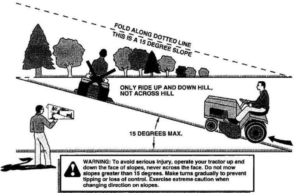
text_image
FOLD ALONG DOTTED LINE THIS IS A 15 DEGREE SLOPE ONLY RIDE UP AND DOWN HILL, NOT ACROSS HILL 15 DEGREES MAX. WARNING: To avoid serious injury, operate your tractor up and down the face of slopes, never across the face. Do not mow slopes greater than 15 degrees. Make turns gradually to prevent tipping or loss of control. Exercise extreme caution when changing direction on slopes.- Fold this page along dotted line indicated above.
- Hold page before you so that its left edge is vertically parallel to a tree trunk or other upright structure.
- Sight across the fold in the direction of hill slope you want to measure.
- Compare the angle of the fold with the slope of the hill.
Get it fixed, at your home or ours!
Your Home
For repair – in your home – of all major brand appliances, lawn and garden equipment, or heating and cooling systems, no matter who made it, no matter who sold it!
For the replacement parts, accessories and owner's manuals that you need to do-it-yourself.
For Sears professional installation of home appliances and items like garage door openers and water heaters.
1-800-4-MY-HOME®
(1-800-469-4663)
www.sears.com
Anytime, day or night
(U.S.A. and Canada)
www.sears.ca
Our Home
For repair of carry-in products like vacuums, lawn equipment, and electronics, call or go on-line for the nearest Sears Parts and Repair Center.
1-800-488-1222 Anytime, day or night (U.S.A. only)
www.sears.com
To purchase a protection agreement (U.S.A.) or maintenance agreement (Canada) on a product serviced by Sears:
1-800-827-6655 (U.S.A.)
1-800-361-6665 (Canada)
© Sears, Roebuck and Co.
® Registered Trademark / ™ Trademark / ™ Service Mark of Sears, Roebuck and Co.