PDMS2004 - DJ Equipment Power Dynamics - Free user manual and instructions
Find the device manual for free PDMS2004 Power Dynamics in PDF.


User questions about PDMS2004 Power Dynamics
0 question about this device. Answer the ones you know or ask your own.
Ask a new question about this device
Download the instructions for your DJ Equipment in PDF format for free! Find your manual PDMS2004 - Power Dynamics and take your electronic device back in hand. On this page are published all the documents necessary for the use of your device. PDMS2004 by Power Dynamics.
USER MANUAL PDMS2004 Power Dynamics
Power Dynamics Professional Audio
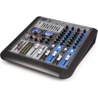
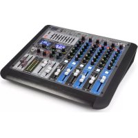
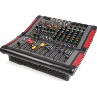
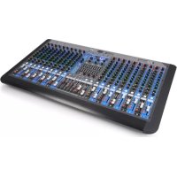
PDM-S2004 20-Channel Mixer
Ref. nr.: 172.628

natural_image
Close-up of a black electronic audio workstation with multiple blue and green audio equipment (no visible text or labels)INSTRUCTION MANUAL
GEBRUIKSAANWIJZING
BEDIENUNGSANLEITUNG
MANUEL D'INSTRUCTIONS
V1.3
Congratulations to the purchase of this Power Dynamics product. Please read this manual thoroughly prior to using the unit in order to benefit fully from all features.
Read the manual prior to using the unit. Follow the instructions in order not to invalidate the warranty. Take all precautions to avoid fire and/or electrical shock. Repairs must only be carried out by a qualified technician in order to avoid electrical shock. Keep the manual for future reference.
- Prior to using the unit, please ask advice from a specialist. When the unit is switched on for the first time, some smell may occur. This is normal and will disappear after a while.
- The unit contains voltage carrying parts. Therefore do NOT open the housing.
- Do not place metal objects or pour liquids into the unit This may cause electrical shock and malfunction.
- Do not place the unit near heat sources such as radiators, etc. Do not place the unit on a vibrating surface. Do not cover the ventilation holes.
- The unit is not suitable for continuous use.
- Be careful with the mains lead and do not damage it. A faulty or damaged mains lead can cause electrical shock and malfunction.
- When unplugging the unit from a mains outlet, always pull the plug, never the lead.
- Do not plug or unplug the unit with wet hands.
- If the plug and/or the mains lead are damaged, they need to be replaced by a qualified technician.
- If the unit is damaged to such an extent that internal parts are visible, do NOT plug the unit into a mains outlet and DO NOT switch the unit on. Contact your dealer. Do NOT connect the unit to a rheostat or dimmer.
- To avoid fire and shock hazard, do not expose the unit to rain and moisture.
- All repairs should be carried out by a qualified technician only.
- Connect the unit to an earthed mains outlet (220-240Vac/50Hz) protected by a 10-16A fuse.
- During a thunderstorm or if the unit will not be used for a longer period of time, unplug it from the mains. The rule is: Unplug it from the mains when not in use.
- If the unit has not been used for a longer period of time, condensation may occur. Let the unit reach room temperature before you switch it on. Never use the unit in humid rooms or outdoors.
-
To prevent accidents in companies, you must follow the applicable guide lines and follow the instructions.
-
Do not repeatedly switch the fixture on and off. This shortens the life time.
- Keep the unit out of the reach of children. Do not leave the unit unattended.
- Do not use cleaning sprays to clean switches. The residues of these sprays cause deposits of dust and grease. In case of malfunction, always seek advice from a specialist.
- Do not force the controls.
- This unit is with speaker inside which can cause magnetic field. Keep this unit at least 60cm away from computer or TV.
- This unit is with built-in lead-acid rechargeable battery. Please recharge the battery every 3 months if you are not going to use the unit for a long period of time. Or the battery may be damaged.
- If the battery is damaged please replace with same specifications battery. And dispose the damaged battery environment friendly.
- If the unit has fallen, always have it checked by a qualified technician before you switch the unit on again.
- Do not use chemicals to clean the unit. They damage the varnish. Only clean the unit with a dry cloth.
- Keep away from electronic equipment that may cause interference.
- Only use original spares for repairs, otherwise serious damage and/or dangerous radiation may occur.
- Switch the unit off prior to unplugging it from the mains and/or other equipment. Unplug all leads and cables prior to moving the unit.
- Make sure that the mains lead cannot be damaged when people walk on it. Check the mains lead before every use for damages and faults!
- The mains voltage is 220-240Vac/50Hz. Check if power outlet match. If you travel, make sure that the mains voltage of the country is suitable for this unit.
- Keep the original packing material so that you can transport the unit in safe conditions.

This mark attracts the attention of the user to high voltages that are present inside the housing and that are of sufficient magnitude to cause a shock hazard.

This mark attracts the attention of the user to important instructions that are contained in the manual and that he should read and adhere to.
The unit has been certified CE. It is prohibited to make any changes to the unit. They would invalidate the CE certificate and their guarantee!
NOTE: To make sure that the unit will function normally, it must be used in rooms with a temperature between 5^ C/41°F and 35^ C/95°F.

Electric products must not be put into household waste. Please bring them to a recycling centre. Ask your local authorities or your dealer about the way to proceed. The specifications are typical. The actual values can slightly change from one unit to the other. Specifications can be changed without prior notice.
Do not attempt to make any repairs yourself. This would invalid your warranty. Do not make any changes to the unit. This would also invalid your warranty. The warranty is not applicable in case of accidents or damages caused by inappropriate use or disrespect of the warnings contained in this manual. Power Dynamics cannot be held responsible for personal injuries caused by a disrespect of the safety recommendations and warnings. This is also applicable to all damages in whatever form.
UNPACKING INSTRUCTION
CAUTION! Immediately upon receiving the product, carefully unpack the carton, check the contents to ensure that all parts are present, and have been received in good condition. Notify the shipper immediately and retain packing material for inspection if any parts appear damage from shipping or the package itself shows signs of mishandling. Save the package and all packing materials. In the event that the product must be returned to the factory, it is important that the product be returned in the original factory box and packing.
If the device has been exposed to drastic temperature fluctuation (e.g. after transportation), do not switch it on immediately. The arising condensation water might damage your device. Leave the device switched off until it has reached room temperature.
POWERSUPPLY
On the label on the backside of the product is indicated on this type of power supply must be connected. Check that the mains voltage corresponds to this, all other voltages than specified, the product be irreparably damaged. The product must also be directly connected to the mains and may be used. No dimmer or adjustable power supply.

Always connect the device to a protected circuit (circuit breaker or fuse). Make sure the device has an appropriate electrical ground to avoid the risk of electrocution or fire.
CONTROL ELEMENTS
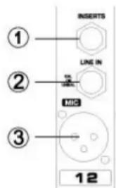
1. Insert Jacks
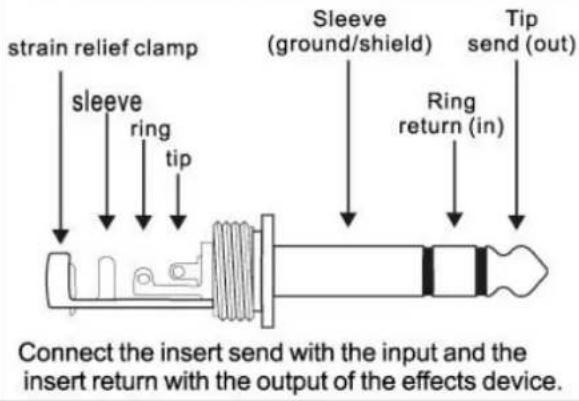
These jacks can be used to insert an external signal-processing device between the equalizer and fader of the corresponding monaural input channel. The insert jacks are ideal for connecting devices such as graphic equalizers, compressors or noise filters into the corresponding channels.
2. Line Input
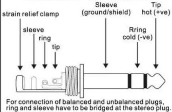
Balanced 6.3mm ( 14 ) jack line inputs. You can connect either balanced or unbalanced phone plugs to these jacks.
3. Microphone Input
Balanced XLR input jacks.
4. 48V Indicator
The red LED lights up when phantom power is switched on. Phantom power is required to operate condenser microphones.
5. Phantom +48V
This switch toggles phantom power on and off. When the switch is on the mixer supplies +48V phantom power to XLR input jack. Turn this switch on when using one or more phantom-powered condenser microphones.
6. TRIM Control
Adjusts the input signal level. To get the best balance between the S/N ratio and the dynamic range, adjust the gain so that the peak indicator (15) lights only occasionally and briefly on the highest input transients. The -60 to +10 scale is the MIC input adjustment range. The 40 to +10 scale is the line input adjustment range.
7. Signal LED Indicator
Check the input signal.
8. Low Out Switch
This switch toggles the HPF on or off. To turn the HPF on, the HPF cuts frequencies below 75Hz.
9. Equalizer
Three-band equalizer adjusts the channel's high, mid and low frequency bands. Setting the knob to the "O" position produces a fiat response in the corresponding band. Turning the knob to the right boosts the corresponding frequency band, while turning to the left attenuates the band.
10. Aux Control
Monitor and effect busses (Aux sends) source their signals via a control from one or more channels and sum these signals to a so-called bus. This bus signal is sent to an aux send connector (for monitoring applications: Mon Out) and then routed, for example, to an active monitor speaker or external effect device. In the latter case, the effects return can then be brought back into the console via the aux return connectors. All monitor and effect busses are mono, are tapped into post EQ and offer amplification of up to +15dB.
11. Pre Switch
With the Pre-switch, you can route an input channel to the headphone/Room section.
12. FX/AUX Control
The aux send marked FX offers a direct route to the built-in effects processor and is therefore post-fader and post-mute.
13. PAN Control
The PAN control determines the position of the channel signal within the stereo image. When working with subgroups, you can use the PAN control to assign the signal to just one output, which gives you additional flexibility in recording situations. For example, when
text_image
INSERTS LINE IN MIC ① ② ③ 12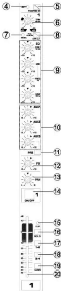
text_image
4 5 6 7 8 9 10 11 12 13 14 15 16 17 18 19 20 30 31 32 33 34 35 36 37 38 39 40 41 42 43 44 45 46 47 48 49 50 51 52 53 54 55 56 57 58 59 60 61 62 63 64 65 66 67 68 69 70 71 72 73 74 75 76 77 78 79 80 81 82 83 84 85 86 87 88 89 90 91 92 93 94 95 96 97 98 99 100routing to subgroups 3 and 4, panning hard left will route the signal to group output 3 only, and panning hard right will route to group output 4 only.
14. ON/OFF Switch
Turn this switch on to send the signal to the buses. The switch lights orange when on.
15. Clip LED
The clip-led lights up when the input signal is driven too high. If this happens, back off the Trim control and, if necessary
16. Solo Switch
The solo switch is used to route the channel signal to the solo bus (Solo In Place) or to the PFL bus (Pre Fader Listen). This enables you to listen to a channel signal without affecting the main output signal. The signal you hear is taken either before the pan control (PFL, mono) or after the pan and channel fader.
17. SUB Switch 1-2
The SUB switch routes the signal to the corresponding subgroups.
18. SUB Switch 3-4
The SUB switch routes the signal to the corresponding subgroups.
19. Main Switch
This switch aligns the main.
20. Channel Fader
Adjusts the level if the channel signal. Use these faders to adjust the balance between the various channels.
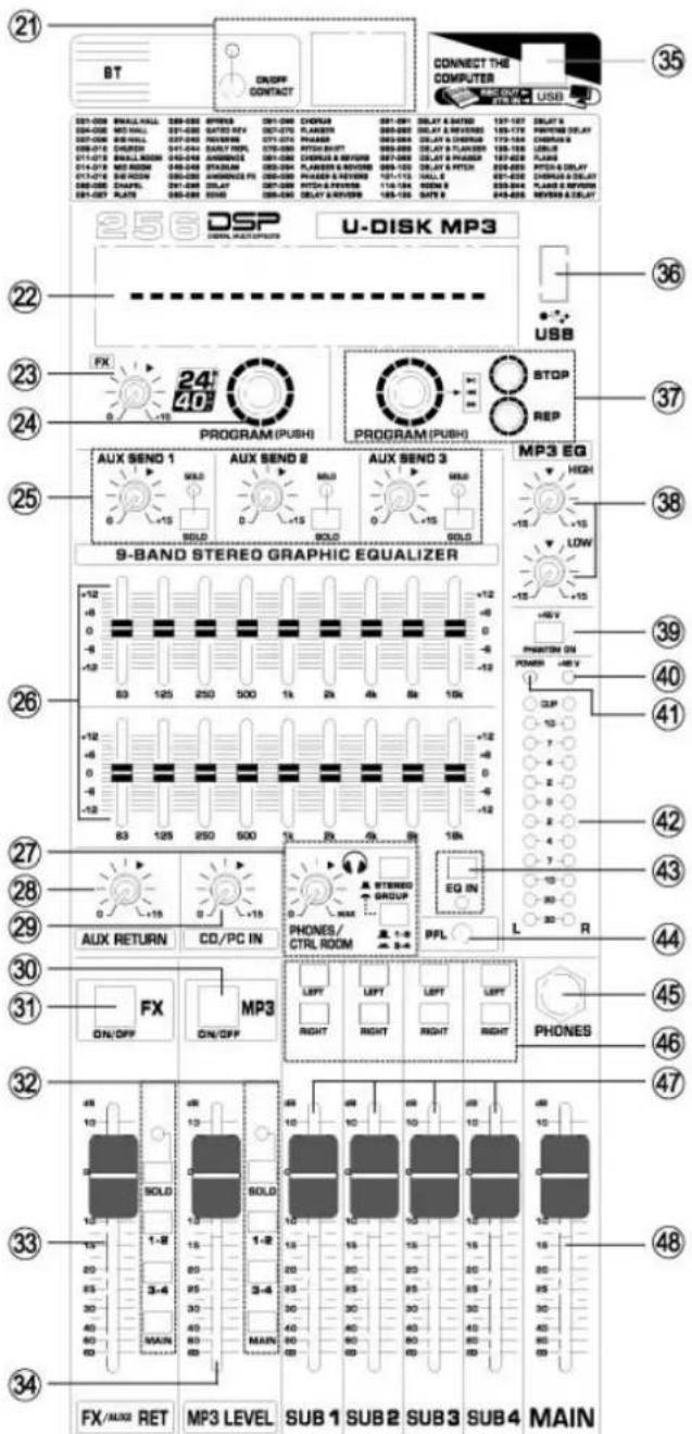
21. BT-Function
Contact mobile phone or tablet. Connecting: Press the "contact switch" for two seconds, then the signal LED light up, use your mobile phone or tablet and choose "PD Power Dynamics" BT- connection.
22. A. Effector Level Light
Show the effect level stronger.
B. Effector Display
Show the kind of effector
C. Mp3 Play Window
Show the MP3 time, song name and other play instruction.
23. FX Control
The aux send jacks carries the master aux mix (from the channel FX controls). You can connect this to an external effects device to process the FX bus. The processed signal can then be brought from the effects device back into the Stereo Aux return jacks.
24. Program Dial
You can select the effect preset by turning the program control. The display flashes with the number of the current preset. To recall the selected preset, press on the button; the flashing stops. You can also recall the selected preset with the foot switch.
25. Aux Control
With this fader you can control the Aux output jack.
26. 9-Band Stereo Graphic Equalizer
The graphic stereo equalizer allows you to tailor the sound to the room acoustics.
27. Headphone/Room Level
Use this control to adjust the output level of headphone.
28. Aux return Stereo
Adjusts the level at which the signal received at the return jacks (L and R), is sent to the stereo L/R bus.
29. CD/PC Control
Adjusts the level of the signal sent from de CD IN jacks. Computer USB audio input & sound control.
30. MP3 Switch same as No. 14.
31. FX Switch same as No. 14.
32. Same as No. 15,16,17,18,19
33. FX Send Fader
Control effect input signal level & Send FX Jack input.
34. MP3 Fader
Control effect input signal level.
35. Computer USB Contacted Jack
Used USB cable line to contact with computer & mixer. Mixer could be play the computer audio and computer could be recording the mixer output audio.
text_image
21 BT DUSPF CONTACT CONNECT THE COMPUTER USB 25 6 DSP U-DISK MP3 22 USB 23 FX 24 24 PROGRAM (PUSH) PROGRAM (PUSH) STOP REP 25 AUX SEND 1 AUX SEND 2 AUX SEND 3 MP3 EQ 9-BAND STEREO GRAPHIC EQUALIZER +12 -6 0 -8 -12 0 -12 -6 0 -12 -12 83 125 250 500 1k 2k 4k 8k 15k SOLD SOLD SOLD SOLD SOLD SOLD SOLD SOLD SOLD SOLD SOLD SOLD SOLD SOLD SOLD SOLD SOLD SOLD SOLD SOLD SOLD SOLD SOLD SOLD SOLD SOLD SOLD SOLD SOLD SOLD SOLD SOLD SOLD SOLD- USB Port
USB: can be play through U-DISK
- MP3/BT Command
STOP: Press shortly to stop playing. Press for seconds for recording, also press 2 seconds to stop recording.
PREV / NEXT: Turning the program control.
PLAY: Press the program control knob.
REP: Repeating of single track or all tracks.
- MP3 EQ
Two-band equalizer adjusts the level if the two bands MP3 player.
- Phantom +48V
This switch toggles phantom power on and off. When the switch is on the mixer supplies +48V phantom power to all channels that have XLR input jacks. Turn this switch on when using one or more phantom-powered condenser microphones.
- 48V Indicator
The red LED lights up when phantom power is switched on. Phantom power is required to operate condenser microphones
- Power indicator
This indicator lights when the mixer power is on.
- VU-Meter
Displays the signal of output.
NOTE: The "0" segment corresponds to the nominal output level. The peak indicator lights up red when the output reaches the clipping level.
- EQ Switch
Use this switch to activate the graphic equalizer.
- PFL indicator
When open the monitor, PFL is lighting.
- Headphone Input
6.3mm (1/4") input jack for connecting a headphone.
- Sub to Main Switch
If this switch is on, the mixer send the signals processed by the Sub faders onto the stereo bus.
- Sub Fader 1-4
Adjusts the signal level sent to the Sub Out (1-4 Jacks).
- Main Mix Fader
You use the high-precision quality faders to control the output level of the main mix.
Adjusts the input signal level. To get the best balance between the S/N ratio and the dynamic range, adjust the gain so that the peak indicator 9 lights only occasionally and briefly on the highest input transients. The -60 to +10 scale is the MIC input adjustment range. The 40 to +10 scale is the line input adjustment range.
text_image
21 BT CROFF CONTACT CONNECT THE COMPUTER USB 35 36 37 38 39 40 41 42 43 44 45 46 47 48 256 DSP U-DISK MP3 FX 24" 40" PROGRAM (PUSH) PROGRAM (PUSH) STOP REP 9-BAND STEREO GRAPHIC EQUALIZER MP3 EQ HIGH LOW -15 -15 -15 -15 -4V PHANTON ON POWER -4V 0.0 10.0 7.0 4.0 2.0 0.0 2.0 4.0 7.0 2.0 2.0 2.0 2.0 2.0 2.0 2.0 2.0 2.0 2.0 2.0 2.0 2.0 2.0 2.0 2.0 2.0 2.0 2.0 2.0 2.0 2.0 2.0 2.0 2.0 B3 125 250 500 1k 2k 4k 6k 10k +12 -12 -12 -12 -12 -12 -12 -12 -12 -12 -12 -12 -12 -12 -12 -12 -12 -12 -12 -12 -12 -12 -12 -12 -12 -12 -12 -12 -12 -12 -12 -12 -12 -12 - 12 B3 125 250 500 1k 2k 4k 6k 10k +12 -12 -12 -12 -12 -12 -12 -12 -12 -12 -12 -12 -12 -12 -12 -12 -12 -12 -12 -12 -12 -12 - 12 AUX SEND 1 AUX SEND 8 AUX SEND 3 SOLD SOLD SOLD SOLD SOLD SOLD SOLD SOLD SOLD SOLD SOLD SOLD SOLD SOLD SOLD SOLD SOLD SOLD SOLD SOLD SOLD SOLD SOLD SOLD SOLD SOLD SOLD SOLD SOLD SOLD SOLD SOLD SOLD SOLD SOLD SOLD SOLD SOLD SOLD SOLD SOLD SOLD SOLD SOLD SOLD SOLD SOLD SOLD SOLD SOLD SOLD TURRAN R SOLD SOLD SOLD SOLD SOLD SOLD SOLD SOLD SOLD SOLD SOLD SOLD SOLD SOLD SOLD SOLD SOLD SOLD SOLD SOLD SOLD SOLD SOLD SOLD SOLD SOLD SOLD SOLD SOLD SOLD SOLD SOLD SOLD SOLD SOLD SOLD SOLD SOLD SOLD SOLD SOLD SOLD SOLD SOLD SOLD SOLD SOLD SOLD SOLD TUR R FX ON/OFF ON/OFF ON/OFF ON/OFF ON/OFF ON/OFF ON/OFF ON/OFF ON/OFF ON/OFF ON/OFF ON/OFF ON/OFF ON/OFF ON/OFF ON/OFF ON/OFF ON/OFF ON/OFF ON/OFF ON/OFF ON/OFF ON/OFF ON/OFF ON/OFF ON/OFF ON/OFF ON/OFF ON/OFF ON/OFF ON/OFF ON/OFF ON/OFF ON/OFF O P L E V L I N M A X M A X M A X M A X M A X M A X M A X M A X M A X M A X M A X M A X M A X M A X M A X M A X M A X M A X M A X M A X M A X M A X M A X M A X M A X M A X M A X M A X M A X M A X M A X M A X M A X M A X N M A X N M A X N M A X N M A X N M A X N M A X N M A X N M A X N M A X N M A X N M A X N M A X N M A X N M A X N M A X N M A X N M A X N M A X N M A X N M A X N M A X N M A X N M A X N M A X N M A XN M A X N M A X N M A X N M A X N M A X N M A X N M A X N M A X N M A X N M A X N M A X N M A X N M A X N M A X N M A X N M A X N M A X N M A X N M A X N M A X N M A X N M A X N M A X N M A X N M A X Y N Y Y Y Y Y Y Y Y Y Y Y Y Y Y Y Y Y Y Y Y Y Y Y Y Y Y Y Y Y Y Y Y Y Y Y Y Y Y Y Y Y Y Y Y Y Y Y Y Y Y Y Y Y Y Y Y Y Y Y Y Y Y Y Y Y Y Y Y Y Y Y Y Y Y Y Y Y Y Y Y Y Y Y Y Y Y Y Y Y Y Y Y Y Y Y Y Y Y Y Y FUT R SOLD 4K 5K 6K 7K 8K 9K 10K 11K 12K 13K 14K 15K 16K 17K 18K 19K 20K 21K 22K 23K 24K 25K 26K 27K 28K 29K 30K 31K 32K 33K 34K 35K 36K 37K 38K 39K 40K 41K 42K 43K 44K 45K 46K 47K 48K 49K 50K 51K 52K 53K 54K 55K 56K 57K 58K 59K 60K 61K 62K 63K 64K 65K 66K 67K 68K 69K 70K 71K 72K 73K 74K 75K 76K 77K 78K 79K 80K 81K 82K 83K 84K 85K 86K 87K 88K 89K 90K 91K 92K 93K 94K 95K 96K 97K 98K 99Ktext_image
INSERTS LINE IN MIS ① ② ③ 12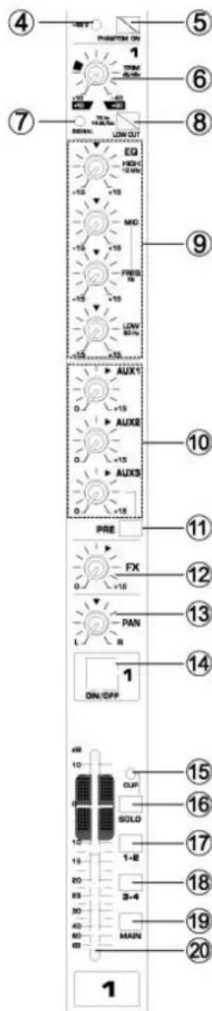
text_image
4 5 6 7 8 9 10 11 12 13 14 15 16 17 18 19 20 3-4 40 50 60 70 80 90 100 110 120 130 140 150 160 170 180 190 200 210 220 230 240 250 260 270 280 290 300 310 320 330 340 350 360 370 380 390 400 410 420 430 440 450 460 470 480 490USB: can be play through U-DISK
- Réglages MP3/BT
text_image
strain relief clamp sleeve tip Sleeve (ground/shield) Tip (signal) Unbalanced " TS connectorBalanced 1/4" TRS connector
text_image
strain relief clamp sleeve ring tip Sleeve (ground/shield) Rring cold (-ve) Tip hot (+ve) For connection of balanced and unbalanced plugs, ring and sleeve have to be bridged at the stereo plug.1/4" TS footswitch connector
text_image
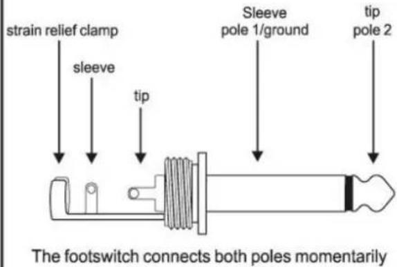
strain relief clamp sleeve tip Sleeve pole 1/ground tip pole 2 The footswitch connects both poles momentarilyInsert send return 1/4" TRS connector
text_image
strain relief clamp sleeve ring tip Sleeve (ground/shield) Ring return (in) Tip send (out) Connect the insert send with the input and the insert return with the output of the effects device.Balanced use with XLR connectors

text_image
1 = ground/shield 2 = hot (+ve) 3 = cold (-ve) Input OutputFor unbalanced use, pin 1 and pin 3 have to be bridged
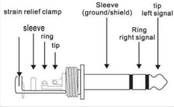
1/4" TRS headphones connector
text_image
strain relief clamp sleeve ring tip Sleeve (ground/shield) Ring right signal tip left signal
text_image
Guitar Microphone Synthesizer Powered monitor speakers CD Player Recorder Active surveillance speakers Effect processor (Exciter) Headphones Professional MixerMICROPHONE INPUTS (XENYX MIC PREAMP)
| Type | XLR, electronically balanced, discrete input circuit |
| Mic E.I.N. (20 Hz - 20 kHz) | |
| @ 0 Ω source resistance | -134 dB / 135.7 dB A-weighted |
| @ 50 Ω source resistance | -131 dB / 133.3 dB A-weighted |
| @ 150 Ω source resistance | -129 dB / 130.5 dB A-weighted |
| Frequency response | <10 Hz - 150 kHz (-1 dB), <10 Hz - 200 kHz (-3 dB) |
| Gain range | +10 to +60 dB |
| Max. input level | +12 dBu @ +10 dB Gain |
| Impedance | approx. 2.6 kΩ balanced |
| Signal-to-noise ratio | 110 dB / 112 dB A-weighted(0 dBu In @ +22 dB gain) |
| Distortion (THD+N) | 0.005% / 0.004% A-weighted |
| Line input | |
| Type | 14 " TRS connector electronically balanced |
| Impedance | approx. 20 kΩ balanced |
| 10 kΩ unbalanced | |
| Gain range | -10 to +40 dB |
| Max. input level | 30 dBu |
FADE-OUT ATTENUATION ^1
(CROSSTALK ATTENUATION)
| Main fader closed | 90 dB |
| Channel muted | 89 dB |
| Channel fader closed | 89 dB |
FREQUENCY RESPONSE
| Microphone input to main out | |
| <10 Hz - 90 kHz | +0 dB / -1 dB |
| <10 Hz - 160 kHz | +0 dB / -3 dB |
| Stereo inputs | |
| Type | 14 " TRS connector, electronically balanced |
| Impedance | approx. 20 kΩ |
| Max. input level | +22 dBu |
| EQ mono channels | |
| Low | 80 Hz / ±15 dB |
| Mid | 100 Hz - 8 kHz/ ±15 dB |
| High | 12 kHz/ ±15 dB |
| EQ stereo channels | |
| Low | 80 Hz / ±15 dB |
| Low Mid | 500 Hz / ±15 dB |
| High Mid | 3 kHz / ±15 dB |
| High | 12 kHz / ±15 dB |
| Aux sends | |
| Type | 14 " TS connector, unbalanced |
| Impedance | approx. 120 Ω |
| Max. output level | +22 dBu |
Stereo aux returns
| Type | 14"TRS connector, |
| electronically balanced | |
| Impedance | approx. 20 kΩ bal. / 10 kΩ unbal. |
| Max. input level | +22 dBu |
| Main outputs | |
| Type | XLR, electronically balanced and 14"TRS balanced |
| 1622FX only: | 14"TS connector unbalanced |
| Impedance | approx. 240 Ω symm. / 120 Ω unbalanced |
| Max. output level | +28 dBu |
| +22 dBu | |
| Control room outputs | |
| Type | 14"TS connector unbalanced |
| Impedance | approx. 120 Ω |
| Max. output level | +22 dBu |
| Headphones outputs | |
| Type | 14"TRS connector, unbalanced |
| Max. output level | +19 dBu / 150 Ω (+25 dBm) |
DSP
| Converter | 24-bit Sigma-Delta,64/128-times oversampling |
| Sampling rate | 40 kHz |
MAIN MIX SYSTEM DATA ^2
| Noise | |
| Main mix @ -αqChannel fader @ -oo | -101 dB-100 dB |
| Main mix @ 0 dB,Channel fader @ -oo | -93 dB-96 dB-87 dB |
| Main mix @ 0 dB,Channel fader @ 0 dB | -81 dB-83 dB-80 dB |
| Power supply | |
| Mains voltage | 100 to 240 V~, 50/60 Hz |
| Fuse | 100 - 240 V ~: T 1.6 A H 250 V |
| Mains connection | Standard IEC receptacle |
The specifications are typical. The actual values can slightly change from one unit to the other. Specifications can be changed without prior notice.
The products referred to in this manual conform to the European Community Directives to which they are subject:
European Union
Tronios B.V.,
7602KR Almelo, The Netherlands
2014/35/EU
2014/30/EU
2011/65/EC

United Kingdom
Tronios Ltd.,
130 Harley Street,
London W1G 7JU, United Kingdom
S.I. 2016:1101
S.I. 2016:1091
S.I. 2012:3032

Specifications and design are subject to change without prior notice.
www.tronios.com
Copyright © 2023 by TRONIOS the Netherlands