
DMM14 ULD - Hand blender AKG - Free user manual and instructions
Find the device manual for free DMM14 ULD AKG in PDF.
| Product type | Digital automatic microphone mixer |
| Brand | AKG |
| Model | DMM14 ULD |
| Dimensions (W x H x D) | 483 x 45 x 220 mm (19" rack, 1U) |
| Weight (with packaging) | 2.9 kg |
| Power supply | 100-240 V AC, 50-60 Hz, max. consumption 75 W |
| Audio inputs | 12 balanced inputs (mic/line) on Phoenix connectors, adjustable gain 0 to 60 dB |
| Phantom power | +48 V, switchable in blocks of 2 inputs, max. 10 mA per input |
| Audio outputs | 2 balanced stereo outputs (OUT1, OUT2) on Phoenix connectors, 1 stereo recording output (RCA), 1 stereo headphone output (6.35 mm jack) |
| Network | LAN port (RJ-45) for remote control and diagnostics, Dante™ interface (RJ-45) on ULD model |
| Additional connectivity | USB port (type B) for firmware update and external control, RS232 serial port, Ethernet cascade (up to 10 units) |
| DSP functions per channel | Level, Treble, Bass, Low Cut, Compressor, Automixing, Priority, Pan, Delay, Routing to REC/USB/OUT, Equalizer, Presets (12 profiles) |
| Output functions | Level, Treble, Bass, Limiter, Balance, Delay, Equalizer (12 bands), Mute |
| Automix algorithm | Dynamic level adaptation, Best Mic On, noise detection |
| Operating temperature | 0°C to 50°C, humidity 10% to 90% non-condensing |
| Protection class | I (earth grounding) |
| Maintenance and cleaning | Disconnect the network cable, clean with a damp cloth (not wet). Do not use solvents, alcohol, or abrasive detergents. |
| Safety | Lock (LOCKED) of controls; do not open the casing; repairs reserved for professionals |
| Package contents | 1 DMM14 ULD, 1 quick guide, 1 IEC EU power cord, 1 IEC US power cord, 1 holding clamp |
| Optional accessories | Cascade cables, external 50 kΩ potentiometer for remote volume control |
| Warranty | Refer to AKG Acoustics GmbH terms |
Frequently Asked Questions - DMM14 ULD AKG
User questions about DMM14 ULD AKG
0 question about this device. Answer the ones you know or ask your own.
Ask a new question about this device
Download the instructions for your Hand blender in PDF format for free! Find your manual DMM14 ULD - AKG and take your electronic device back in hand. On this page are published all the documents necessary for the use of your device. DMM14 ULD by AKG.
USER MANUAL DMM14 ULD AKG
REFERENCE FOR DIGITAL
Read the manual before using the equipment!
131 MODE D'EMPLOI
Level
- Treble
Bass
Low Cut
- Limiter
- Compressor
- Automixing
- Priority
Pan/Balance
Delay
- Routing To REC
- Routing To USB
Equalizer
- Preset
- Routing To Out 1
- Routing To Out 2
Monitoring
Mute
Level
- Treble
Bass
- Low Cut
- Compressor
- Automixing
- Priority
Pan
- Routing To Out 1
- Routing To Out 2
- Routing To Rec
- Routing To USB
Monitoring
Mute
Level
- Treble
Bass
- Limiter
Balance
Delay
Equalizer
Monitoring
Mute
1.1 Purpose of the manual 70
1.2 Retention of the manual 70
1.3 Liability 70
1.4 Warranty 70
2 SCOPE OF SUPPLY 71
2.1 Packing unit 71
2.2 Optional accessories 71
3 SAFETY AND ENVIRONMENT 72
3.1 Safety 72
3.2 Required knowledge and areas of responsibility of the operators/users 73
3.3 Explanation of the symbols used 73
3.4 Correct use 74
3.5 Incorrect use 74
3.6 Environment 74
4 DECLARATION OF CONFORMITY 74
5 DESCRIPTION 75
5.1 Summary 75
5.2 Technical data 75
5.3 Front: Description of the controls 77
5.3.1 Controls for input channels 77
5.3.2 Operating mode /SYSTEM CONTROL 78
5.3.3 Control for stereo outputs 78
5.3.4 Modulation display for stereo outputs 78
5.3.5 Stereo headphone output 78
5.4 Rear: Description of the controls 79
5.4.1 Inputs 80
5.4.2 Gain control 81
5.4.3 Phantom power 81
5.4.4 Stereo master bus output channel 83
5.4.5 Stereo record output 83
5.4.6 Serial control via RS232 84
5.4.7 USB port 84
5.4.8 LAN port 85
5.4.9 Expansion/cascading 85
5.4.10 DanteTM network 86
5.5 Automix algorithm 86
5.5.1 Dynamic level adjustment 87
5.5.2 Best Mic On 87
5.5.3 Noise Detect 87
5.6 Expansion/cascading 87
6 INSTALLATION AND CONNECTION 89
6.1 Installation 89
6.2 Cascade devices (optional) 89
6.3 Connecting microphones and accessories 89
6.4 Connect to the mains power supply 90
7 FUNCTIONAL DESCRIPTION 91
7.1 Control concept 91
7.2 Operation of the rotary knobs 91
7.2.1 Display of the audio level / VU function 92
7.3 SYSTEM CONTROL 92
7.3.1 SYSTEM CONTROL functions 92
7.3.2 Input channel modes 93
7.3.3 Output channel modes 93
7.3.4 Functions of the stereo headphone output (monitoring output) 93
7.4DSP functions 94
7.4.1 LEVEL 94
7.4.2 TREBLE 95
7.4.3 BASS 97
7.4.4 LOW CUT 99
7.4.5 LIMITER 101
7.4.6 COMPRESSOR 103
7.4.7 AUTOMIXING 104
7.4.8 PRIORITY 105
7.4.9 PAN/BALANCE 106
7.4.10 DELAY 108
7.4.11 ROUTING TO REC 109
7.4.12 ROUTING TO USB 110
7.4.13 EQUALIZER 111
7.4.14 PRESET 112
7.5 LOCKED 114
| Publisher | AKG Acoustics GmbH | AKG ACoustICS, U.S. |
| Laxenburger Straße 254 | 8500 Balboa Blvd. Dock 15 | |
| 1230 Wien | Northridge, CA 91329 | |
| Austria | U.S.A. | |
| Tel: +43 (0)1 86654-0 | Tel: +1 818 920-3224 | |
| Fax: +43 (0)1 86654-8800 | ||
| sales@akg.com | akgusatechsupport@harman.com | |
| Copyright | © 2015 AKG Acoustics GmbH | |
| All rights reserved. | ||
| The information contained in this manual, including any drawings and photos provided, are the intellectual property of AKG Acoustics GmbH. | ||
| In accordance with copyright law, it is not permitted for this documentation or parts thereof to be reproduced or transmitted for any purpose in any form using any means, whether electronic or mechanical, by photocopying, recording or using information storage and information processing systems without the express, written consent of AKG Acoustics GmbH. | ||
| Forwarding to third parties is not permitted. This manual should be returned to us on request. | ||
| FCC Statement | Note: This equipment has been tested and found to comply with the limits for a Class B digital device, pursuant to part 15 of the FCC Rules. These limits are designed to provide reasonable protection against harmful interference in a residential installation. This equipment generates, uses and can radiate radio frequency energy and, if not installed and used in accordance with the instructions, may cause harmful interference to radio communications. However, there is no guarantee that interference will not occur in a particular installation. If this equipment does cause harmful interference to radio or television reception, which can be determined by turning the equipment off and on, the user is encouraged to try to correct the interference by one or more of the following measures: | |
| • Reorient or relocate the receiving antenna. | ||
| • Increase the separation between the equipment and receiver. | ||
| • Connect the equipment into an outlet on a circuit different from that to which the receiver is connected. | ||
| • Consult the dealer or an experienced radio/TV technician for help. | ||
| This device complies with Part 15 of the FCC Rules. Operation is subject to the following two conditions: (1) this device may not cause harmful interference, and (2) this device must accept any interference received, including interference that may cause undesired operation. | ||
| Shielded cables and I/O cords must be used for this equipment to comply with the relevant FCC regulations. Changes or modifications not expressly approved by the party responsible for compliance could void the user's authority to operate this equipment. | ||
| Updates | This manual may be modified without prior notice and does not represent any obligation on the part of AKG Acoustics GmbH. | |
| Version 1.0 | ||
| Publication date | July 2015/EN | |
1 General
1.1 Purpose of the manual
This manual is intended to enable you to:
- operate the equipment safely.
- use the equipment correctly.
1.2 Retention of the manual
Print out this manual and keep it carefully or store it electronically at an easily accessible location.
Pass this manual on to subsequent owners.
This manual is an important part of the equipment.
Liability
1.3 Liability
AKG Acoustics GmbH accepts no liability, if:
- The equipment is used for purposes other than those described under correct usage.
- Damage is incurred due to incorrect operation
- Unauthorized or non-permitted modifications having been carried out.
- Damage due to out of date documentation.
Warranty
1.4 Warranty
AKG Acoustics GmbH accepts no liability for damage, if
- incorrect operation.
- Unauthorized or non-permitted modifications having been carried out.
- Damage due to out of date documentation.
2 Scope of supply
Packing unit
2.1 Packing unit
Check that the package contains all the parts given below. If anything is missing, please contact your AKG dealer.
- 1 x DMM14 U, DMM14 UL or DMM14 ULD
1 x Quick Start Guide - 1 x IEC EU standard mains cable
- 1 x IEC US standard mains cable
- 1 x mating plug terminal
Optional accessories
2.2 Optional accessories
Optional accessories can be found at www.akg.com. Your dealer will be happy to advise.
3 Safety and environment
Safety
3.1 Safety

Caution: Risk of damage
- Protect the equipment against
- direct sunlight
- the impact of significant dust and humidity
-rain - vibrations or knocks.
- Do not spill any liquids on the equipment and do not allow any other objects to drop through the ventilation slits into the equipment.
- Do not place any containers filled with liquid on the equipment.
- The equipment must only be used in dry rooms.
- The equipment must only be opened, serviced and repaired by authorized personnel. The equipment contains no user-serviceable parts.
- Before connecting the equipment to power, check that the AC mains voltage stated on the integrated power adapter is identical to the AC mains voltage available where the equipment will be used.
- Only operate the equipment on a mains voltage between the 100 and 240V AC. Using adapters with different output voltage or current types may cause serious damage to the equipment.
- If any solid or liquid should get into the equipment, shut down the system immediately. Disconnect the power cable from the power outlet at once and have the equipment checked by our customer service department.
- If the equipment is not going to be used for a longer time, disconnect the mains cable from the power outlet. Please note that if you switch the equipment off while leaving the mains cable plugged in, it is not fully isolated from the power network.
-
Do not place the equipment near heat sources such as radiators, heating ducts, amplifiers, etc.
-
To avoid hum or interference, route all audio lines, particularly those connected to the microphone inputs, away from power lines of any type. If you use cable ducts, be sure to use separate ducts for the audio lines.
- Clean the equipment with a moistened (not wet) cloth only. Be sure to disconnect the power adapter from the power outlet beforehand. Never use caustic or scouring cleaners or cleaning products containing alcohol or solvents since these may damage the enamel and plastic parts.
- Only use the equipment for the applications described in this manual. AKG cannot accept any liability for damages resulting from improper handling or misuse.
3.2 Required knowledge and areas of responsibility of the operators/users
- Qualified expert personnel are able to determine risks and avoid hazards when using the product, based on their professional training, education and experience.
3.3 Explanation of the symbols used

Caution: Risk of damage
Not following the instructions may damage the equipment.

Warning: Hazard due to electric shock
Hazardous situation: Not following the instructions may result in minor or serious injury.

Describes useful information and application notes for efficient operation of the equipment.

Provides reference to more in-depth information and downloads online.

Describes information on the correct disposal of the components described.
3.4 Correct use
The Digital Automatic Microphone Mixer DMM14 U (UL, ULD) U (UL, ULD) is designed solely for mixing audio signals.
3.5 Incorrect use
Any use not given under correct use is regarded as incorrect.
3.6 Environment

- The packaging is recyclable. Dispos of the packaging in an appropriate recycling collection system.
- In case of scrapping the equipment, separate the housing, electronics and cables and dispose of all the components in accordance with the appropriate waste disposal regulations.

4 Declaration of Conformity
This product conforms to the standards listed in the Declaration of Conformity. You can download the Declaration of Conformity at www.akg.com or request it by email from sales@akg.com.
5 Description
Summary
5.1 Summary
The DMM14 U (UL, ULD) is a 19" Digital Automatic Microphone Mixer. Internal signal processing takes place digitally and on four master buses (stereo). The inputs and outputs are available as analog and digital.
It has 12 balanced mono inputs that can be configured as microphone inputs or line inputs (e.g. for wireless microphone receivers).
On the output side it has one balanced master output, one stereo recording output and one stereo headphone output.
It has a USB port that can be used as both an input and an output.
Inputs and outputs are controlled via LAN and DanteTM networks (optional).
The device has a wide-range power supply unit and is connected to the power network using the mains cable supplied.
In addition to multiple DSP digital signal processing functions, the DMM14 U (UL, ULD) also has innovative automatic mixing functions.
Up to ten DMM14 U (UL, ULD) can be cascaded if the twelve balanced inputs are not sufficient for your application.
5.2 Technical data
General
General
| Dimensions | Standard housing for rack mounting, 1 |
| HU | |
| 483 (W) x 45 (H) x 220 (D) mm | |
| Weight (with packaging) | 2.9 kg |
| Permissible ambient tempera-ture | 0 °C ... 50 °C |
| Air humidity in operation | 10 % ... 90 %, non-condensing |
| Protection rating I | |
| Power adapter | Power adapter | |
| Input voltage 100 ... 240 V AC | ||
| Mains frequency 50 ... 60 Hz | ||
| Max. power intake 75 Watt | ||
| Output voltages 24 V | ||
| Inputs | Balanced inputs – Preamplifier | |
| Gain 0 dB ... 60 dB | ||
| Max. input level +20 dBu | ||
| Common mode rejection >70 dB | ||
| Dynamics >120 dB | ||
| Signal-to-noise ratio (S/N) >90 dB | ||
| Input impedance >8 kΩ | ||
| Equivalent input noise -127 dBu | ||
| Balanced inputs – Phantom power | ||
| Phantom voltage 48 V DC | ||
| Max. supply current per input 10 mA | ||
| Infeed resistors 2 x 6.8 kΩ | ||
| Balanced inputs – Analog/digital converters | ||
| Data format | 24 Bit | |
| Sample frequency | 48 kHz | |
| Outputs | Recording and total output | |
| Max. output level | +20 dBu | |
| Dynamics >110 dB | ||
| Signal-to-noise ratio (S/N) >90 dB | ||
| Min. load impedance | <100 Ω | |
| Digital/analog conversion for recording, monitoring and totals output | ||
| Data format | 24 Bit | |
| Sample frequency | 48 kHz | |
Front controls
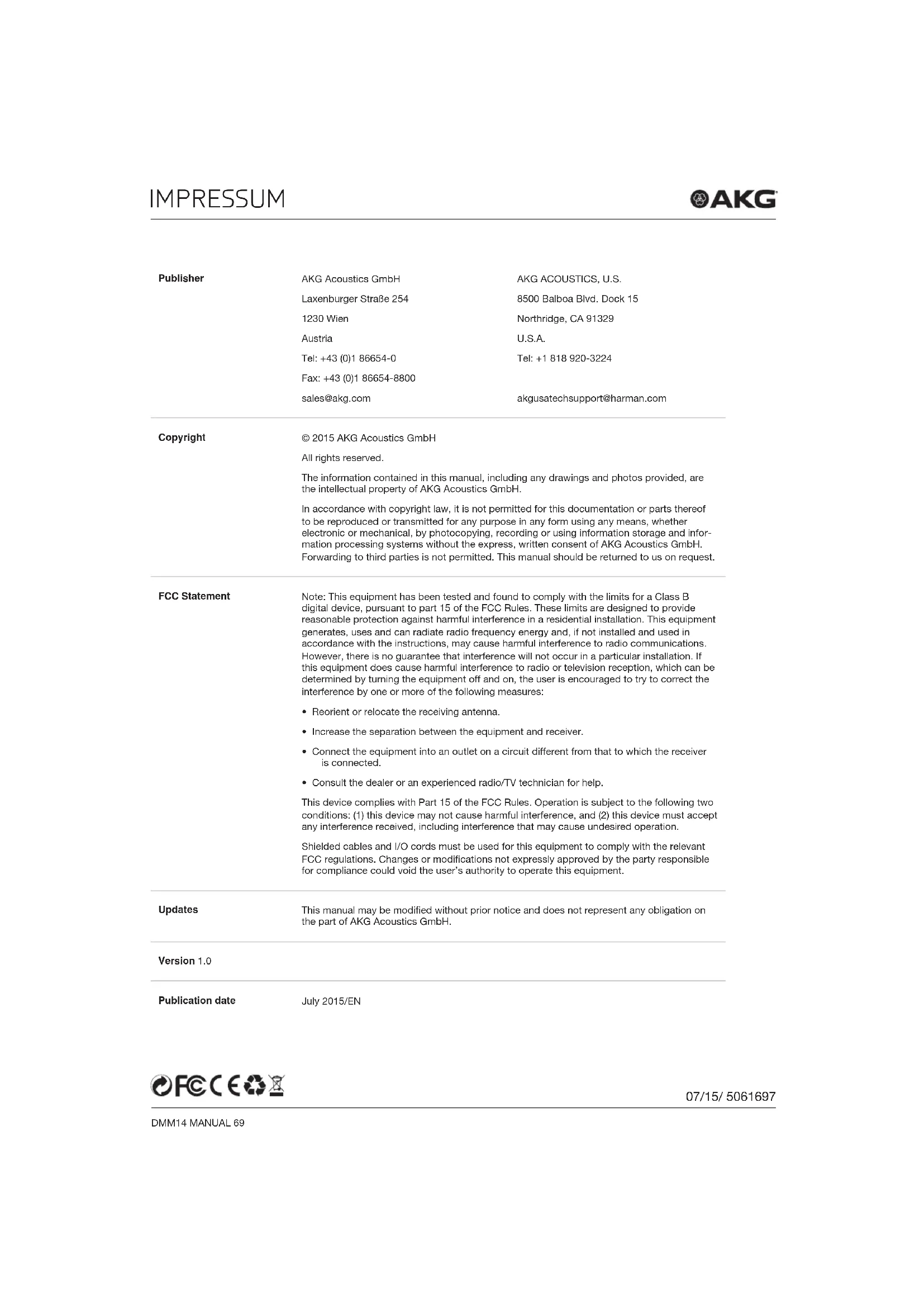
5.3 Front: Description of the controls
There is a total of nine controls on the front.
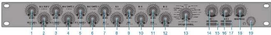
Figure 1: Front of the DMM14 U (UL, ULD)
The following table describes the controls on the front of the DMM14 U (UL, ULD):
No. Description
1 to 12 Microphone or line inputs
13 Operating mode / SYSTEM CONTROL
14, 16 Stereo outputs 1 and 2
15, 17 Modulation display for stereo outputs 1 and 2
18 Stereo headphone output
19 Socket for headphone connection
The parameters of the selected audio functions are changed using the controls.
Rotary knobs for inputs
5.3.1 Controls for input channels
The DMM14 U (UL, ULD) has 12 balanced input channels to connect low ohm, dynamic microphones or capacitor microphones and other signal sources, e.g. receivers for wireless microphones. There is a control for each input channel (1 to 12).
Each input channel has a green LED ON and a red LED PEAK.
LED ON
ON is lit when the input channel is prioritized in automatic mode. If the Automix function is switched off, ON is lit continuously.
LED PEAK
PEAK is lit if the signal on an input channel comes close to the maximum modulation limit. In this case, the level should be reduced or the input sensitivity changed.

The input sensitivity is modified using the gain regulator on the rear of the connected equipment.
SYSTEM CONTROL
5.3.2 Operating mode / SYSTEM CONTROL
The DMM14 U (UL, ULD) has numerous functions such as volume, trebles, bass, auto-mixer functions etc. These functions are selected on the SYSTEM CONTROL (13).
Rotary knobs for outputs
5.3.3 Control for stereo outputs
The controls for the stereo output channels are labeled OUT 1 (14) and OUT 2 (16). This control is used to change the following parameters on the output channel:
Volume
- Treblerrange
Bass range
- Limitation response
Balance and delay
Modulation display
5.3.4 Modulation display for stereo outputs
The modulation display (15, 17) under the control for the stereo output channels shows the output level in dB.
Headphone output
5.3.5 Stereo headphone output
Both inputs and outputs can be picked up on the stereo headphone output (18).
Rear controls
5.4 Rear: Description of the controls
On the rear are the sockets for the input channels and output channels as well as the mains connection, etc.
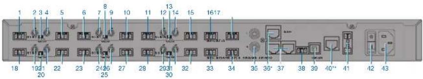
Figure 2: Rear of the DMM14 U (UL, ULD)
*only available with DMM14 ULD **only available with DMM14 UL and DMM14 ULD
The following table describes the controls on the rear of the DMM14 U (UL, ULD):
No. Description
| 1, 5, 6, 10, 11, 15, Input channels | |
| 18, 22, 23, 27, 28, 32 | |
| 2, 4, 7, 9, 12, 14, 19, Gain control | |
| 21, 24, 26, 29, 31 | |
| 3, 8, 13, 20, 25, 30 Phantom power | |
| 16, 33 Stereo output channel, left | |
| 17, 34 Stereo output channel, right | |
| 35 Stereo record output | |
| 36 DanteTM: *only available with DMM8 ULD | |
| 37 Expansion sockets | |
| 38 Serial control (RS232) | |
| 39 USB port | |
| 40 Modular jack (RJ-45) socket: **only available for DMM8 UL and DMM8 ULD |
No. Description
41 Phoenix terminal (ground / remote control)
42 Mains connection
43 Mains switch
Input channels
5.4.1 Inputs
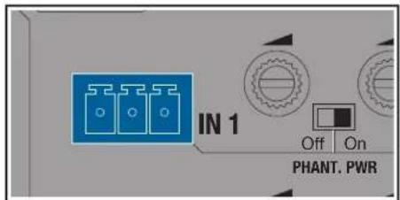
Figure 3: Input
The 12 balanced input channels (1, 5, 6, 10, 11, 15, 18, 22, 23, 27, 28, 32) can be accessed via 3-pin Phoenix sockets. These are labeled IN 1 to IN 12. The input levels can be controlled with the rotary knobs IN 1 to IN 12 on the front panel.
A switch for the phantom power and a gain control for every channel is located between two phoenix sockets.
The assignment is labeled via socket IN 3 with:
Pin1=a
Pin2=b
Pin3=
Gain controller
5.4.2 Gain control
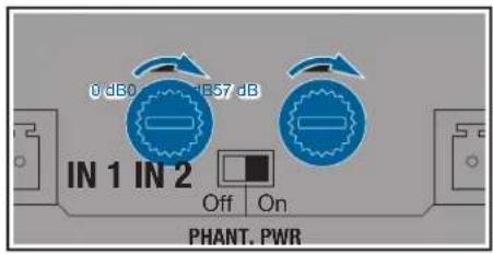
Figure 4: Gain controller
The associated gain control is located next to every input channel (2, 4, 7, 9, 12, 14, 19, 21, 24, 26, 29, 31) to set the input level. The gain controls are equipped with integrated switch for the left side stop.
The input level is set at 0 dB when the left end stop is reached. By turning the control clockwise the gain can be increased by max. 57 dB.
Phantom power
5.4.3 Phantom power
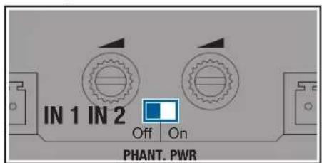
Figure 5: Phantom power
The device is equipped with six switches for phantom power (3, 8, 13, 20, 25, 30).
The corresponding slide switch activates the phantom power supply of +48V for the inputs located on the left and right.
The slide switch is labeled PHANT. PWR. Two input channels are always activated simultaneously. The phantom power is activated when the slide switch is in the On position.
The corresponding slide switch activates the phantom power supply of +48V for the inputs located on the left and right.
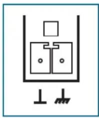
Ground connection
Figure 6: Phoenix terminal
A Phoenix terminal connects the housing to the 0V potential of the power supply.

Only bridge the 0V potential with the grounding (factory setting) or connect it to the central system ground, as otherwise the phantom power has no reference point and will not function.
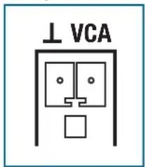
Analog control
Figure 7: Phoenix terminal
A linear 50k potentiometer at the VCA input, labeled "VCA" and "", allows you to vary the master volume.
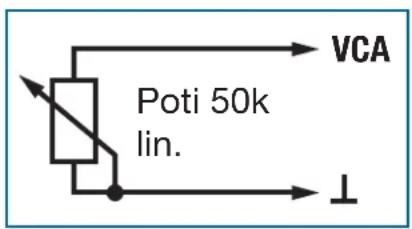
Figure 8:VCA
The linear potentiometer is connected to the VCA input as shown above. The resistance at the VCA input is changed by turning the potentiometer This value is input and the volume is changed accordingly The left setting signifies 0% while the right setting signifies 100% .
The output level depends on the master control and the remote level control. The remote level control has the same effect on both masters
Stereo output
5.4.4 Stereo master bus output channel
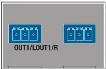
Figure 9: Stereo master output
The equipment has two balanced master outputs (16, 17, 33, 34). They are accessible via four 3-pin Phoenix sockets. The outputs are labeled OUT 1/L and OUT 1/R or OUT 2/L and OUT 2/R.
The OUT 1 or OUT 2 control on the front can be used to make settings on the output level of the corresponding stereo output channel.
The allocation of individual channels to the balanced master outputs is freely configurable.
Stereo record output
5.4.5 Stereo record output
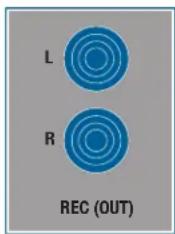
Figure 10: Stereo record output
Two RCA jacks, labeled REC (OUT) (35) are available for connecting stereo recording equipment. The allocation of the individual channels to the unbalanced stereo recording output can be configured as desired.
Serial control
5.4.6 Serial control via RS232
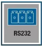
Figure 11: Serial control
The RS232 socket (38) permits software updates to be carried out and to operate the device via an external control (e.g.: AMX). The pin assignment is as follows:
Pin Function
| 1 GND |
| 2 TxD |
| 3 RxD |
USB port
5.4.7 USB port
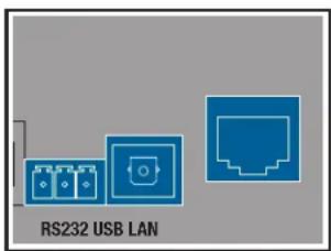
Figure 12: USB port
The USB port (39) can be used to connect the device to a PC to perform firmware updates and permit external control.
The connection is established via a standard MS Windows driver. An Apple driver needs to be installed manually if required.
LAN port
5.4.8 LAN port
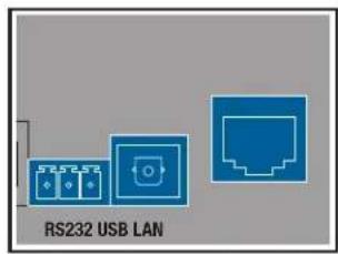
Figure 13: LAN port
The LAN port (40) permits software updates to be carried out and to operate the device via an external control (e.g.: AMX).
Remote control and remote diagnostics are also possible via a web server.
This web server provides a simple and functional user interface that can be opened via a browser and that permits access via LAN infrastructure.
Simultaneous operation via the front panel of the automixer and via the web server is possible: it is preferable for the inputs to be handled via the web server, however.
The automixer is provided with protocol allowing it to be actuated via external software or wirelessly via APP.
These applications can add considerably more functions depending on the programming type and scope, and provide a more complex graphic interface depending on the terminal.
Cascading
5.4.9 Expansion/cascading
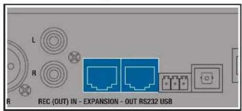
Figure 14: Expansion
The 8-pin (RJ-45) modular jacks (37) can be used to connect up to 10 devices.
The audio master and the status signal for the automix algorithm are transmitted.
The audio transmission via cascading is carried out in 24Bit. This does not impair the noise values.
DanteTM network
5.4.10 DanteTM network
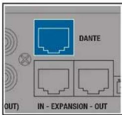
Figure 15: DanteTM
The DMM14 ULD is equipped with an 8-pin (RJ-45) modular jack labeled DANTE (19).
All inputs and outputs are thereby automatically routed to the DanteTM network.
The inputs are routed to the DanteTM network after signal processing (treble, bass,...) and after the automix algorithm as direct-out signals.
The output masters are routed before the balance regulator, before volume out and before limiter to the DanteTM network as direct out signals.
Settings must be made via the DanteTM receiver unit (e.g. mixing desk).
When cascading automixers, note that only the channels available locally on an automixer can be transmitted via the Dante™ network. If in addition the inputs of another, cascaded device are required, this device must also have a standalone Dante™ interface.
If multiple devices are also to be operated in the automix, these must also be connected via cascading: Specifically, in addition to the master signals, the control signals of the automix algorithm are also transmitted.
Algorithm for Automix
5.5 Automix algorithm
The unit's automix algorithm has 3 basic functions which assess the amount by which an input signal is to be attenuated and the output signal's output level. The following functions and parameters flow into the automix algorithm:
Dynamic level adjustment
Best Mic On
- Noise Detect
Level adjustment
5.5.1 Dynamic level adjustment
The master of all input channels is determined on an ongoing basis. This value is used as the reference value.
If the input channel level is very close or over the reference value, this channel will be assessed as dominant and will be slightly attenuated. If the input channel level is well below the reference value, this is assessed as ambient noise and be severely attenuated.
If a channel is no longer assessed as dominant, this falls at 1 dB/second and all other nondominant channels increase with the same constant so that the master output level remains constant. The upward adjustment of a channel takes between 3 ms and 5 ms.
Best Mic On
5.5.2 Best Mic On
With two microphones that are positioned close together there is the disadvantage that comb filter effects may arise by canceling the frequency components. To suppress these unnaturally dull or hollow signals, only the microphone channel with the highest level is assessed as dominant and switched on.
Noise Detect
5.5.3 Noise Detect
Permanently present interfering signals, whose amplitude are large enough to be assessed as dominant, but whose level and frequency changes are too low, are not assessed as dominant.
Interfering signals such as noise from fans and air-conditioning units are recognized and not used as activation criteria for microphone channels.
Expansion for cascading
5.6 Expansion/cascading
Up to ten devices can be cascaded if the number of inputs on a single device are not sufficient.
The device has two 100 MBit/s Ethernet ports. These are used to exchange control data and audio communication between cascaded devices.
This means that an automixing system can be realized with:
- 60 inputs
20 outputs
10 stereo headphone outputs
The master buses for OUT, REC-OUT and HEADPHONE are accessible to the entire system of cascaded devices. Every unit adds its input channels to the master buses, which are transferred via the Ethernet interface. Every unit can monitor and output the master buses.
The automix algorithm also transfers its control data via this interface. This allows the automix algorithm to function system-wide.
6 Installation and connection
The following steps are required for installation and connection of the DMM14 U (UL, ULD):
- Installation
- Cascade devices (optional)
- Connect microphones and accessories
- Connect to the mains power supply
6.1 Installation
To install the device, proceed as follows:
Step Description

1 Mount the device into your 19" rack using 4 appropriate rack bolts.
Ensure that the device is securely screwed onto the rack.
Alternatively, the device can be positioned on a stable surface.

6.2 Cascade devices (optional)
Caution: Risk of damage
It is only permitted for this connection to be carried out by authorized, qualified personnel.
It is not permitted to connect the first device in the cascade to the last device.
For the cabling of the individual devices via the expansion sockets, see 8.4 Cascading devices on page 117
6.3 Connecting microphones and accessories

Read the operating instructions for your microphones and accessories for connection.
Connect the microphones and accessories to the rear of the DMM14 U (UL, ULD) as follows:
Step Description
1 Connect microphones and other signal sources (e.g. receivers for wireless microphones) to the IN inputs
2 Connect outputs OUT 1/L, OUT 2/L and OUT 1/R, OUT 2/R to a mixing desk or amplifier
3 Connect the RCA jacks on the stereo recording output REC (OUT) to a recording device
6.4 Connect to the mains power supply
Caution: Risk of damage
Do not connect the unit to the power network until you have established all the audio connections!
Ensure that the input voltage on the DMM14 U (UL, ULD) corresponds to the mains voltage.
To connect the device to the mains, proceed as follows:
Step Description
1 Connect the mains power supply cable to the appropriate socket on the rear panel of the DMM14 U (UL, ULD)
2 Plug the power supply cable into a mains socket

7 Functional description
7.1 Control concept
The device is controlled using the total of 16 rotary knobs on the front panel. These are labeled IN 1 to IN 12, SYSTEM CONTROL, OUT 1, OUT 2 and HEADPHONE.
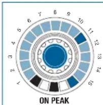
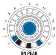
The rotary knobs on the inputs are each surrounded by an LED ring with 15 yellow LEDs, one green LED and one red LED. The SYSTEM CONTROL rotary knobs and the rotary knobs on the outputs are surrounded by 15 yellow LEDs. The control display under the outputs has 6 green, one yellow and one red LED.
The LED rings help to visualize the rotary knob setting or display signal levels.
Rotary knob
7.2 Operation of the rotary knobs
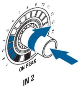
Figure 16: Rotary knob
- Turn the rotary knob clockwise or counter-clockwise to make changes to inputs and outputs and function settings. These changes are shown on the LED ring around the rotary knob. The starting point and the increments on the LED ring will vary according to the function.
- Briefly pressing the SYSTEM CONTROL rotary knob switches the display on the LED rings to VU meter, the display of the actual audio level present.
When the VU meter mode is activated, the LEVEL LED flashes on the SYSTEM CONTROL rotary knob. Pressing the SYSTEM CONTROL rotary knob again deactivates the VU meter mode.

SYSTEM CONTROL
7.2.1 Display of the audio level / VU function
With the LEVEL function selected, the level set is displayed on the LED rings on the inputs and outputs.
7.3 SYSTEM CONTROL
The SYSTEM CONTROL rotary knob provides the option of selecting various functions on the device.
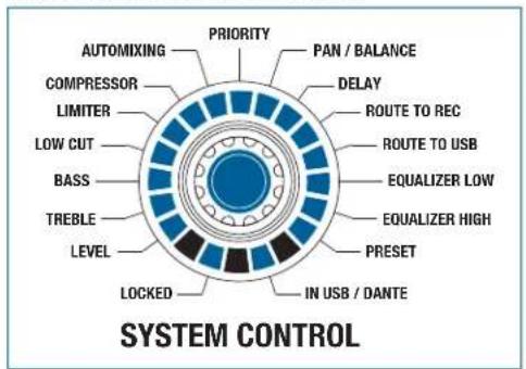
Figure 17:SYSTEM CONTROL
For selecting the functions and setting parameters, see 8.1 SYSTEM CONTROL: Changing parameters on the device on page 115
SYSTEM CONTROL modes
7.3.1 SYSTEM CONTROL functions
The following functions can be selected via the SYSTEM CONTROL:
Level
- Treble
Bass
Low Cut
- Limiter
- Compressor
- Automixing
- Priority
Pan/Balance
Delay
- Routing To REC
- Routing To USB
Equalizer
- Preset
Other functions given can be selected by pressing individual rotary knobs or combinations of multiple knobs:
- Routing To Out 1
- Routing To Out 2
Monitoring
Mute
Input channel modes
7.3.2 Input channel modes
The input channels have the following function controls:
Level
- Treble
Bass
- Low Cut
- Compressor
- Automixing
- Priority
Pan
- Routing To Out 1
- Routing To Out 2
- Routing To Rec
- Routing To USB
Monitoring
Mute
Output channel modes
7.3.3 Output channel modes
The output channels have the following function controls:
Level
- Treble
Bass
- Limiter
Balance
Delay
Equalizer
Monitoring
Mute
7.3.4 Functions of the stereo headphone output (monitoring output)
The exception to this is the HEADPHONE rotary knob. The stereo headphone output is always
located in the LEVEL mode, regardless of the SYSTEM CONTROL rotary knob setting.
DSP functions
7.4 DSP functions
Given below are explanations of the individual functions and their operation and effects.
LEVEL
7.4.1 LEVEL
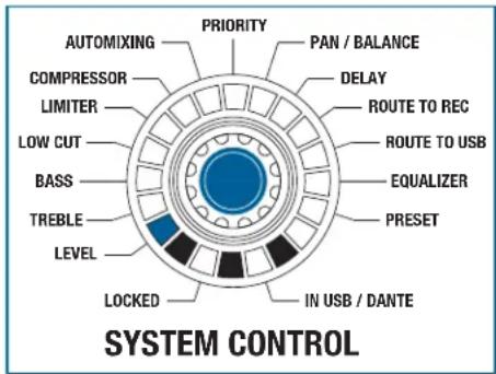
Figure 18: LEVEL function
All the input and output channels can be controlled in the LEVEL mode.
Turning the rotary knob clockwise increases the volume. Turning it count- er-clockwise decreases the volume.
The settings range from - to +15dB (acoustic feedback). The adjustment takes place in the appropriate increments.
At + 15dB the entire LED ring is illuminated and the acoustic feedback is no longer provided.
The adjustable increments are equal to 1 dB per click from -12 dB to +15 dB. One LED equals 3 dB. The adjustable increments are equal to 3 dB per click from -12 dB to - . One LED equals 9 dB.
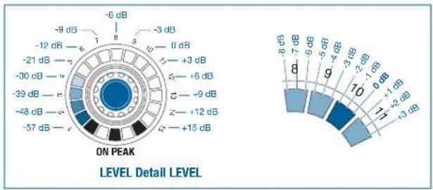
Figure 19: LEVEL detail
One LED (no. 10) is brighter than the other LED fields to help you find the 0 dB position more easily; the LED field illuminates as soon as the 0 dB level is reached (after the third click, see "Level" detail).
Pressing the SYSTEM CONTROL rotary knob in the LEVEL function switches the display of the inputs and outputs from amplification to modulation.

7.4.2 TREBLE
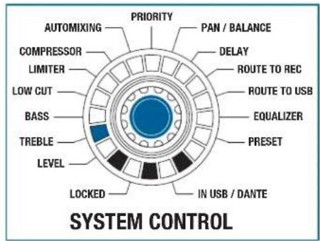
Figure 20: TREBLE function
All inputs and outputs can be controlled in TREBLE mode.
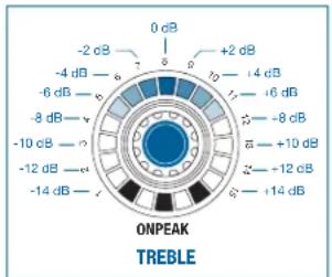
Figure 21: Adjustment range of the LED ring for the TREBLE function
The TREBLE raises or lowers the audio signal's treble range. The filter is designed as a first order treble shelving filter. The cut-off frequency is 10kHz .
The settings range from -14 dB to +14 dB. Only the upper middle LED lights up (0 dB) with linear adjustment. More LEDs light up on the left side as the rotary knob is turned further to
the left.
More LEDs light up on the right side as the rotary knob is turned further to the right.
The adjustable increments are equal to 2 dB per click and also correspond to one LED.
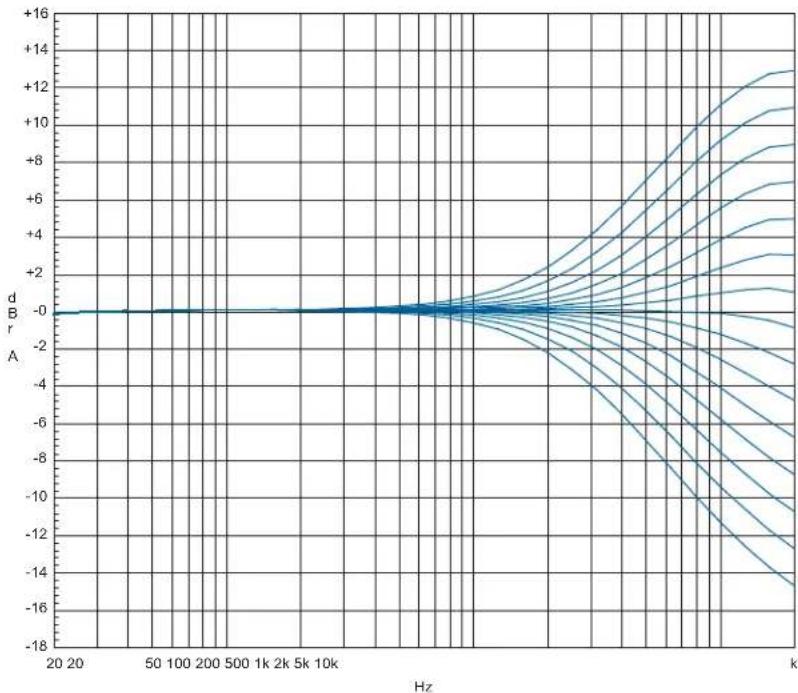
Figure 22: Adjustment range for the TREBLE function
BASS
7.4.3 BASS
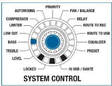
Figure 23: BASS function
All the input and output channels can be controlled in the BASS mode.
The BASS raises or lowers the audio signal's bass range. The filter is designed as a first order bass shelving filter. The cut-off frequency is 100Hz .
The settings range from -14 dB to +14 dB. Only the upper middle LED lights up (0 dB) with linear adjustment. More LEDs light up on the left side as the rotary knob is turned further to
the left.
More LEDs light up on the right side as the rotary knob is turned further to
the right.
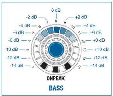
Figure 24: Adjustment range of the LED ring for the BASS function
The adjustable increments are equal to 2 dB per click and also correspond to one LED.
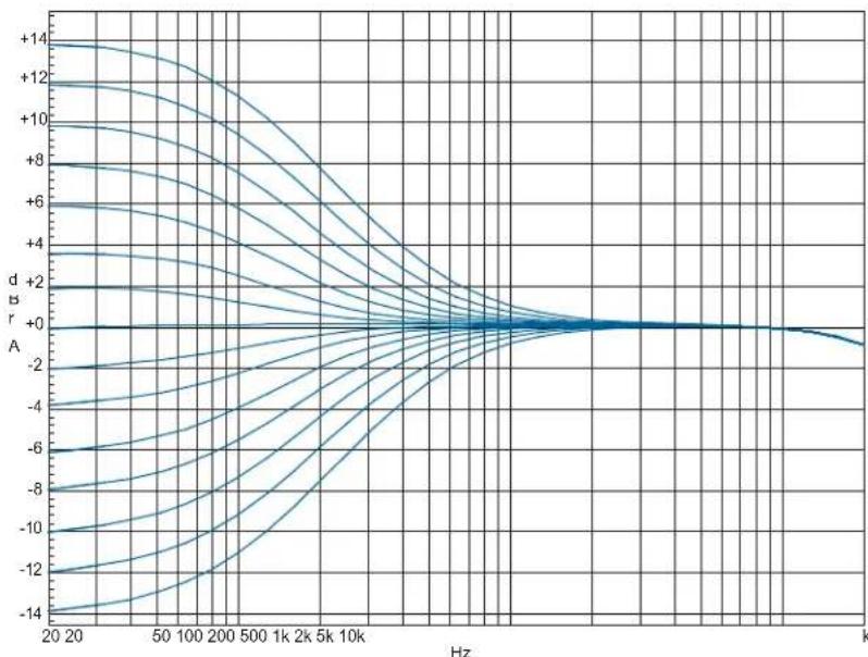
Figure 25: Adjustment range for the BASS function
LOW CUT
7.4.4 LOW CUT
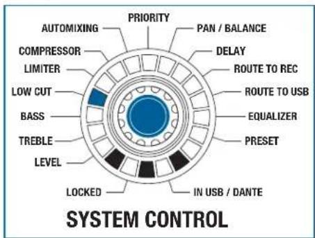
Figure 26: LOW CUT function
All the input channels can be controlled in the LOW CUT function.
The LOW CUT function suppresses low-frequency interference noise. He low cut filter is designed as a second order high-pass filter. The cut-off fre
quency can be raised by turning the rotary knob in a clockwise direction and lowered by turning it counter-clockwise.
The settings range from 0Hz (no effect) to 150Hz (severe attenuation).
One LED is illuminated at 0Hz , while the entire LED ring is illuminated at 150 Hz.
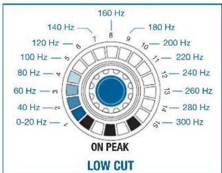
Figure 27: Adjustment range of the LED ring for the LOW CUT function
The adjustable increments are equal to 20Hz per click and also correspond to one LED.
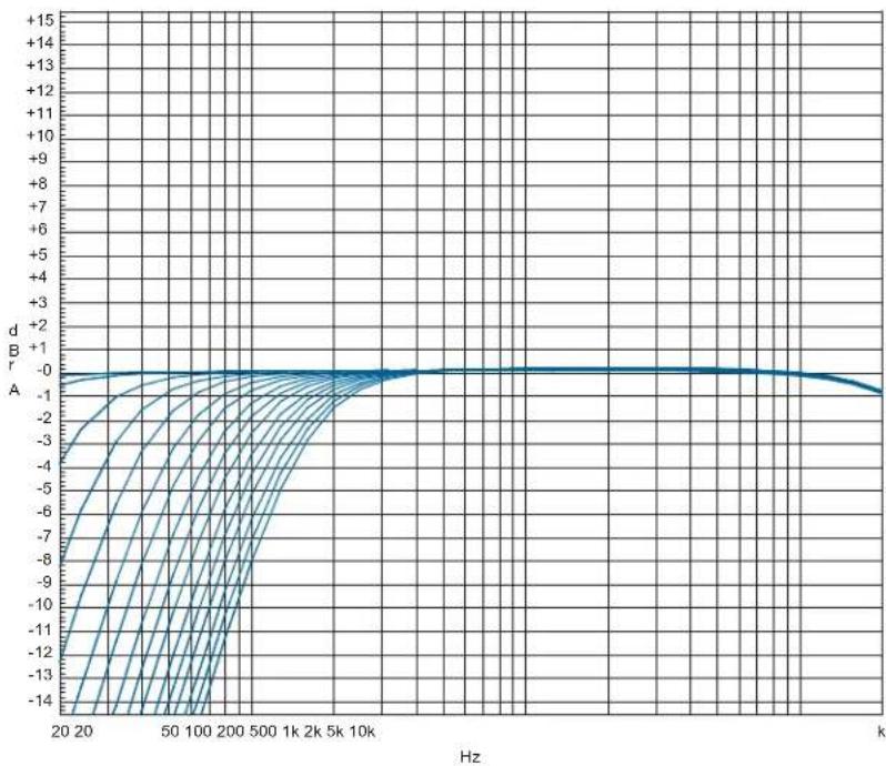
Figure 28: Adjustment range for the LOW CUT function
LIMITER
7.4.5 LIMITER
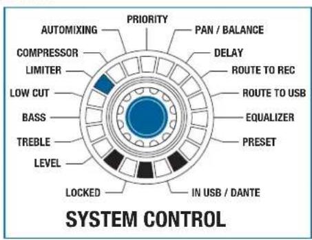
Figure 29: LIMITER function
All the output channels can be controlled in the LIMITER mode.
Turning the rotary knob in a clockwise direction increases the effect, while turning it counterclockwise dampens the effect.
The settings range from +20 dBu to -25 dBu. One LED is illuminated at +20 dBu, while the entire LED ring is illuminated at -25 dBu.
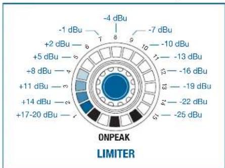
Figure 30: Increments on the LED ring for the LIMITER function
The adjustable increments are equal to 3 dB per click, corresponding to one LED.
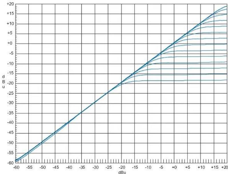
Figure 31: Adjustment range for the LIMITER function
COMPRESSOR
7.4.6 COMPRESSOR
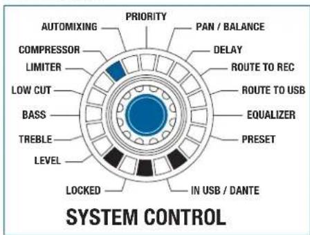
Figure 32: COMPRESSOR function
All the input channels can be controlled in the COMPRESSOR mode.
The compressor ratio is fixed. It has a value of 1:2. Turning the rotary knob in a clockwise direction increases the effect, while turning it counterclockwise dampens the effect.
The settings range from +20dBu to -25dBu . One LED is illuminated at +20dBu , while the entire LED ring is illuminated at -25dBu .
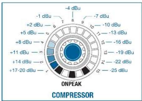
Figure 33: Increments on the LED ring for the COMPRESSOR function
The adjustable increments are equal to 3 dBu per click, corresponding to one LED.
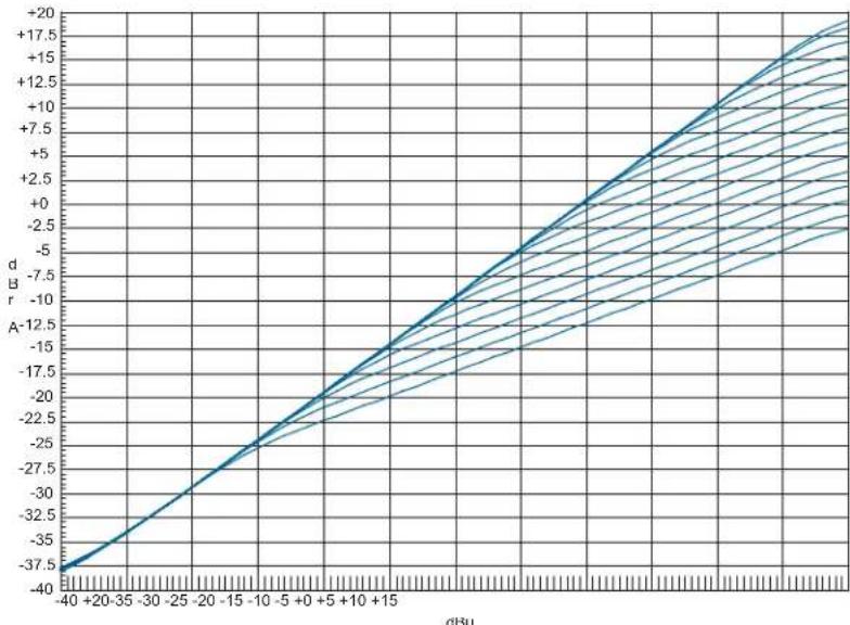
Figure 34: Adjustment range for the COMPRESSOR function
AUTOMIXING
7.4.7 AUTOMIXING
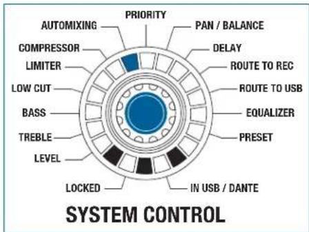
Figure 35: AUTOMIXING function
All the input channels can be controlled in the AUTOMIXING mode.
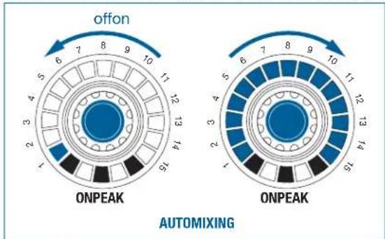
Figure 36: Adjustment range for the AUTOMIXING function
The automatic mixing function for the relevant channel is switched on by turning a rotary knob in the clockwise direction. (Entire LED ring is illuminated) Turning the rotary knob counterclockwise
switches the automatic mixing function off. (Only one LED is illuminated)
Pressing the rotary knob also switches the function on or off.

PRIORITY
7.4.8 PRIORITY
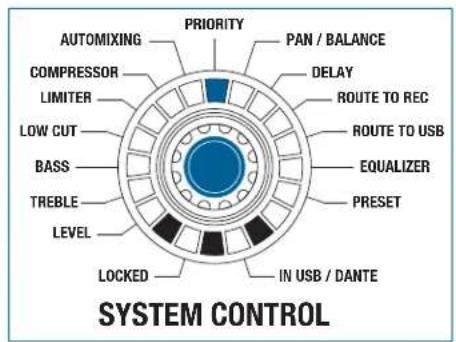
Figure 37: PRIORITY function
This function can only be active on one single input.

The PRIORITY mode allows you to select which input channel will function as the priority channel. The priority channel then receives a 6 dB advantage in the signal detection in connection with the AUTOMIXING mode.
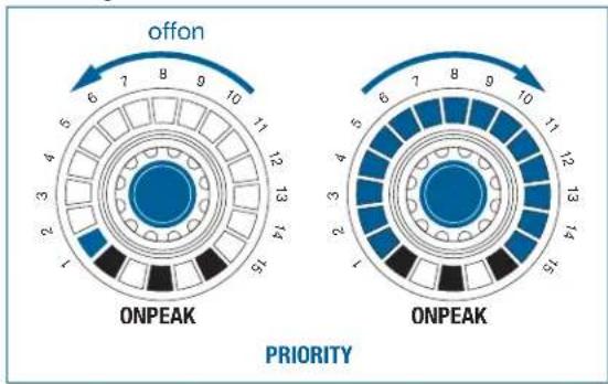
Figure 38: Adjustment range for the PRIORITY function
The function for the relevant channel is switched on by turning a rotary knob in the clockwise direction. (Entire LED ring is illuminated). Turning the rotary knob counter-clockwise switches the functions off (only one LED is illuminated).

Pressing the rotary knob also switches the function on or off.
Switching on the PRIORITY function on an input channel turns off the function on the previously activated channel.
PAN/BALANCE
7.4.9 PAN/BALANCE

Figure 39: PAN/BALANCE function
The PAN / BALANCE mode allows all the input channels in the panorama and the balance of
all the output channels to be controlled.
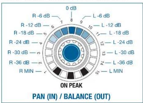
Figure 40: Increments on the LED ring for the PAN/BALANCE function

Balance means assignment of a main signal to the output.
Only the upper middle LED lights up (0 dB) with linear adjustment. This LED (0 dB) is also considered to be the starting point for a clockwise or counterclockwise rotation. More LEDs light up on the left side as the rotary knob is turned further to
the left. More LEDs light up on the right side as the rotary knob is turned further to
the right.
If no further output is required from the left output channel of a stereo output, turn the balance controller to the right.
In mono inputs, the signal is assigned equally to stereo left and right as standard. If the input is to be assigned to the left only, turn the rotary knob for the input to the left when the PAN function is active.
The adjustable increments are equal to 6 dB per click and also correspond to one LED.
DELAY
7.4.10 DELAY
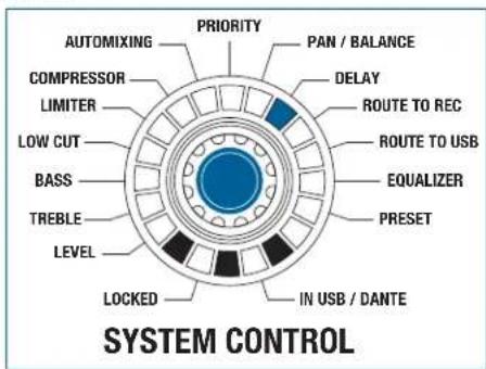
Figure 41: DELAY function
The DELAY function is used to control outputs OUT 1 and OUT 2. The outputs can be delayed using this function.
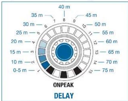
Figure 42: Increments on the LED ring for the DELAY function
The settings range from 0m to 75m . One LED is illuminated at 0m , while the entire LED ring is illuminated at 75m .
The adjustable increments are equal to 1 m per click. 5 m is equal to one LED.
ROUTING TO REC
7.4.11 ROUTING TO REC
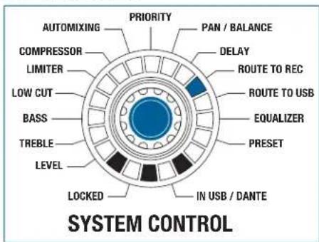
Figure 43: ROUTING TO REC function
All the input channels can be controlled in the ROUTING TO REC mode.

Figure 44: Adjustment range for the ROUTING TO REC function
The function for the relevant channel is switched on by turning the rotary knob in the clockwise direction (entire LED ring is illuminated). Turning the rotary knob counter-clockwise switches the function off (only one LED is illuminated).
Pressing the rotary knob also switches the function on or off.
Switching this on sets the input channel to the OUT 1 master bus.

ROUTING TO USB
7.4.12 ROUTING TO USB
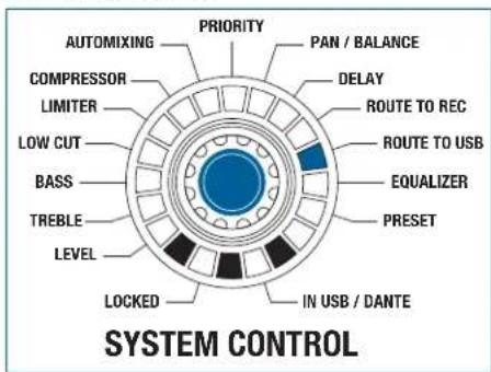
Figure 45: ROUTING TO USB function
All the input channels can be controlled in the ROUTING TO USB mode.
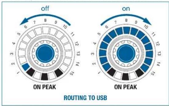
Figure 46: Adjustment range for the ROUTING TO USB function
The function for the relevant channel is switched on by turning the rotary knob in the clockwise direction (entire LED ring is illuminated). Turning the rotary knob counter-clockwise switches the function off (only one LED is illuminated).
Pressing the rotary knob also switches the function on or off.
Switching this on sets the input channel to the USB OUT master bus.

EQUALIZER
7.4.13 EQUALIZER
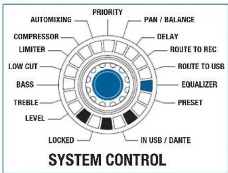
Figure 47: EQUALIZER function
The EQUALIZER function controls outputs OUT 1 and OUT 2: The adjustment is the same for the left and right channel.
The room equalization can be performed in 12 bands.
Pressing the OUT 1 rotary knob activates the setting for OUT 1 while pressing the OUT 2 rotary knob activates the setting for OUT 2.
The raising or lowering of the bands is performed by the 12 rotary knobs for the input channels. The adjustment range extends from -14 dB to +14dB. Only the upper middle LED lights up with linear adjustment. More LEDs light up on the left side as the rotary knob is turned
further to the left. More LEDs light up on the right side as the rotary knob is turned further to
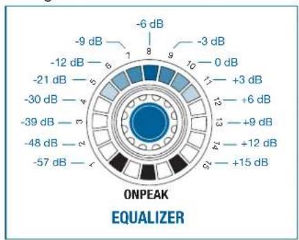
the right.
Figure 48: Increments on the LED ring for the EQUALIZER function

The adjustment takes place in 2 dB increments.
The center frequencies of the sub-bands are assigned at half-octave intervals.
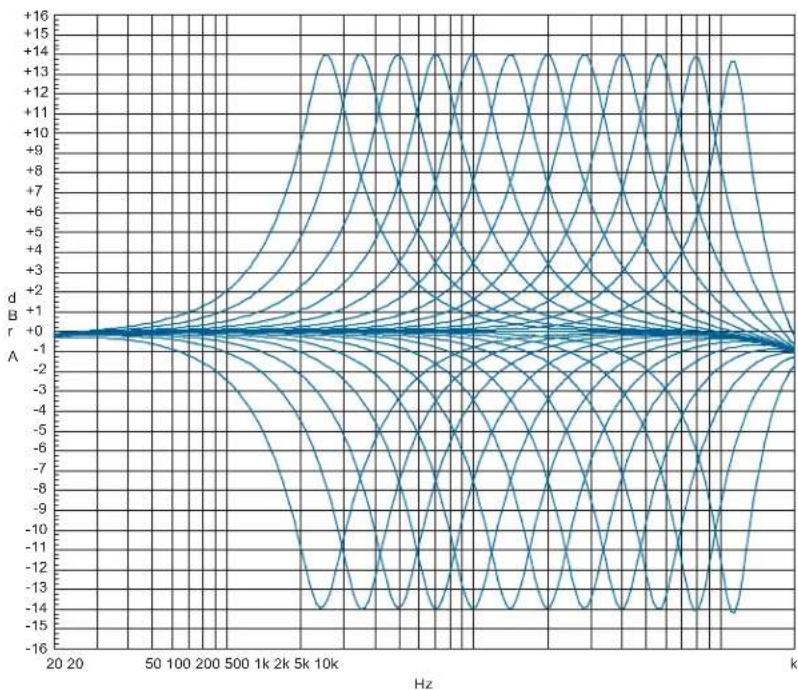
Figure 49: Adjustment range for the EQUALIZER function
PRESET
7.4.14 PRESET
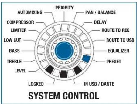
Figure 50: PRESET function
It is possible store and load 12 different device configurations or device presets (LEVEL, TREBLE, BASS, ..., EQUALIZER).
To do this, the PRESET function is selected on the SYSTEM CONTROL. In addition to the 12 device presets, there is also a work preset: All changes in the settings initially only have an effect on that preset. To store changes permanently, the work preset must be stored under one of the available device presets. Loading a device preset overwrites the work preset and makes it active immediately. After re-starting the device, the last work preset becomes active with the last settings made.
The 12 input rotary knobs provide access to the presets, and their configuration.
IN1/USBL EQ250Hz
IN 2/USB R E0350Hz

IN 3 / DANTE 1 EQ500 Hz
Figure 51: PRESET configurations
If only LED 1 lights on an LED ring, this storage location is not configured (see Figure 51, encoder IN 3/15).
If all LEDs and the red PEAK LED are lit, this storage location is assigned and selected (see Figure 51, encoder IN 1 / 13).
If only LED 1 and the red PEAK LED are on, this storage location is assigned but not selected (see Figure 51, encoder IN 2 / 14).
For more information, see 8.7 Using presets on page 118.
LOCKED
7.5 LOCKED
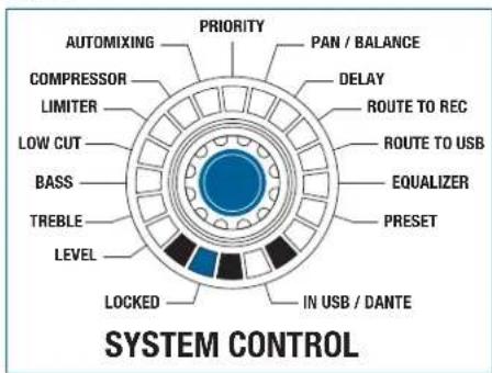
Figure 52: LOCKED function
In LOCKED mode the rotary knobs or the entire unit are protected against improper use by means of locking.
For more information, see 8.11 Activate/deactivate LOCKED on page 121
8 Operating the device
SYSTEM CONTROL
8.1 SYSTEM CONTROL: Changing parameters on the device
To change the parameters on the device, proceed as follows:
Step Description
1 Turn to the required function on the SYSTEM CONTROL rotary knob, turning the rotary knob until the LED is lit at the required function.
2 Modify the inputs with the selected function using the IN 1 to IN 12 rotary knobs
3 Modify the outputs with the selected function using the OUT 1 and OUT 2 rotary knobs

The stereo record output does not have any setting options.
5 minutes after the last change, the SYSTEM CONTROL rotary knob goes back to the LEVEL mode. 1 minute after the last change, the set value is saved automatically.
8.2 Configuring microphones on the DMM14 U (UL, ULD)
To configure the connected microphones and accessories, proceed as follows:
Step Description

1 Press the slider switch and gain control on the rear of the DMM14 U (UL, ULD)
- Select the amplification of the input signals between 0 dB and +57 dB.
- Higher amplification of the input signals is suitable for microphones with a low output level.
- Lower amplification is recommended for microphones with a high output level.
- If you are using capacitor microphones, determine which supply voltage or supply devices these require.
- If your capacitor microphones are suitable for phantom power, switch the phantom power on. To do this, switch the PHANT. PWR slider switch to ON.
2 Switch on the device with the main power switch

Caution: Risk of damage
When using wireless microphones, switch off the phantom power on the inputs where you have connected a receiver to avoid damage to the receiver.
8.3 Monitoring the inputs/outputs
To monitor the inputs and outputs, proceed as follows:
Step Description
1 Hold down the HEADPHONE rotary knob and press to select one or more monitoring source rotary knob
- They are switched in mono simultaneously to the left and right headphone channel.
2 Change monitoring source by pressing on another monitoring source.
- The previous monitoring source is switched off.

With inputs, multiple sources can be monitored.
The output can be monitored individually and in stereo.
The REC (OUT) output cannot be monitored.
8.4 Cascading devices

Caution: Risk of damage
It is only permitted for this connection to be carried out by authorized, qualified personnel.
It is not permitted to connect the first device in the cascade to the last device.
To cable the individual devices with the expansion sockets, proceed as follows:
Step Description
1 Cascade the devices as follows using CAT5+ connection cables:
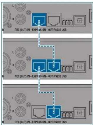

For cascading we recommend using only cables from the AKG range of accessories.
All devices are equivalent for the user in terms of their function and response. In cascading, all functions of the individual devices are retained.
Feed via USB and DanteTM
8.5 Feed via USB and DanteTM
8.5.1 Processing the feed
To feed the input signals via USB or Dante™, proceed as follows:
Step Description
1 Press the SYSTEM CONTROL rotary knob twice briefly (double-click)
The 12 input controls are switched over for operation.
The LEDs IN USB and IN USB/DANTE are permanently lit
Changes to the input controls no longer affect the 12 analog inputs; only digital inputs 13 to 24
- The remaining operation is the same as on the analog level
The inputs from USB Port are assigned to channels 13 (IN1 / USB L) and 14 (IN2 / USB R), for devices without DanteTM interface the digital inputs 15 to 24 are without function and inactive.
For devices with DanteTM interface, the remaining digital input channels from channel 15 are assigned as follows:
All digital inputs have the same signal processing functionalities as the analog inputs.
8.6 Activating phantom power

PRESET
Only bridge the 0V potential with the grounding (factory setting) or connect it to the central system ground, as otherwise the phantom power has no reference point and will not function.
8.7 Using presets
The presets on the DMM14 U (UL, ULD) function in a very similar way to the presets on a car radio.
8.7.1 Selecting a preset
To select a preset, proceed as follows:
Step Description
1 With SYSTEM CONTROL, select the PRESET function
2 Briefly press the rotary knob for the corresponding input or output.
- An acoustic signal (beep) is sounded.
3 Release the rotary knob after the beep
Device preset is loaded to work preset
- Settings for the selected device preset are active immediately (all LEDs lit)
8.7.2 Programming a preset
To program a preset, proceed as follows:
Step Description
1 With SYSTEM CONTROL, select the PRESET function
2 Press input rotary knobs (1 to 12) for between 3 and 5 seconds.
- An acoustic signal (beep) is sounded.
3 Release the rotary knob after the beep
- The current settings from the work preset are stored under the selected device preset (all LEDs lit)
8.7.3 Deleting a preset
To delete a preset, proceed as follows:
Step Description
1 With SYSTEM CONTROL, select the PRESET function
Step Description
2 Press the rotary knob for the corresponding input or output for between 8 and 10 seconds.
- An acoustic signal (beep) is sounded.
3 Release the rotary knob after the beep
- The device preset is deleted and cannot be selected (empty storage location, LED 1 lit)
MUTE
8.8 Using MUTE
8.8.1 Activating MUTE
Inputs and outputs can be switched to MUTE. Proceed as follows:
Step Description
1 In the LEVEL function, briefly press the rotary knob for the corresponding input or output.
The corresponding channel is muted.
- All LEDs previously lit will flash.
- The current volume is stored.

The MUTE function cannot be used for the HEADPHONE rotary knob!
8.8.2 Deactivating MUTE
To deactivate the MUTE function proceed as follows:
Step Description
1 Briefly press the rotary knob for the corresponding input or output.
- MUTE function for the corresponding channel is deactivated.
- The volume previously stored is applied.
ROUTING TO OUT
8.9 Activating ROUTING TO OUT
8.9.1 For an input
All inputs can be routed to the OUT output. Proceed as follows:
Step Description
1 Press and hold the OUT rotary knob
Press the rotary knobs on the required input simultaneously
- The corresponding input is routed to the OUT master bus.
8.9.2 For multiple inputs
To route multiple inputs to OUT, proceed as follows:
Step Description
1 Press and hold the OUT rotary knob
Press the rotary knob of the required inputs
- The corresponding inputs are routed to the OUT master bus.
8.10 Deactivating ROUTING TO OUT
To deactivate the ROUTING TO OUT function, proceed as follows:
Step Description
1 Press the rotary knob of the required input
- ROUTING TO OUT is deactivated for the corresponding input.
LOCKED
8.11 Activate/deactivate LOCKED
The following elements can be locked using the LOCKED function:
SYSTEM CONTROL rotary knob
- Complete unit
- Individual channels
Lock rotary knob
8.11.1 Locking the SYSTEM CONTROL rotary knob
To lock the SYSTEM CONTROL rotary knob, proceed as follows:
Step Description
1 Press the SYSTEM CONTROL rotary knob for longer than 3 seconds
The LOCKED LED is lit.
- Turning the rotary knob has no function.
- All other rotary knobs are in LEVEL mode and can still be operated.
Unlock rotary knob
8.11.2 Unlocking the SYSTEM CONTROL rotary knob
To unlock the SYSTEM CONTROL rotary knob, proceed as follows:
Step Description
1 Press the SYSTEM CONTROL rotary knob for longer than 3 seconds
The rotary knob lock is removed.
- The LOCKED LED is no longer lit.
- The rotary knob is in the basic LEVEL position.
Lock unit
8.11.3 Locking the complete unit
To lock the complete unit, proceed as follows:
Step Description
1 Press the SYSTEM CONTROL rotary knob at the same time as the OUT rotary knob for longer than 3 seconds
The LOCKED LED is lit.
- The original settings are stored.
- Turning the rotary knob has no function.
- All other rotary knobs are in LEVEL mode and can still be operated.
Unlock unit
8.11.4 Unlocking the complete unit
To unlock the complete unit, proceed as follows:
Step Description
1 Press the SYSTEM CONTROL rotary knob at the same time as the OUT rotary knob for longer than 3 seconds
The rotary knob lock is removed.
- The LOCKED LED is no longer lit.
- The rotary knobs are in the basic LEVEL position.
Unlock channels
8.11.5 Unlocking individual channels
To unlock individual channels, proceed as follows:
Step Description
1 Lock the complete unit, to do this press the SYSTEM CONTROL rotary knob at the same time as the OUT rotary knob for longer than 3 seconds
The LOCKED LED is lit.
- The original settings are stored.
- Turning the rotary knob has no function.
- All other rotary knobs are in LEVEL mode and can still be operated.
2 Remove the lock on the required channel by pressing the rotary knob for the required channel for longer than 3 seconds
Lock channels
8.11.6 Locking individual channels
To lock individual channels, the complete unit is locked first and the lock is then removed for all channels that are not to be locked.
To lock individual channels, proceed as follows:
Step Description
1 Lock the complete unit, to do this press the SYSTEM CONTROL rotary knob at the same time as the OUT rotary knob for longer than 3 seconds
The LOCKED LED is lit.
- The original settings are stored.
- Turning the rotary knob has no function.
- All other rotary knobs are in LEVEL mode and can still be operated.
2 Remove the lock on all channels by pressing the rotary knob for the required channels for longer than 3 seconds.

The status conditions that were set before the channels or the complete unit was locked, are retained even after the DMM14 U (UL, ULD) is switched of and back on!
Copy configurations
8.12 Copying configuration data
The copy function can be used to copy individual or multiple settings (LEVEL, TREBLE, BASS, LOWCUT, LIMITER and COMPRESSOR) on an input to one or more other inputs.
8.12.1 Copying individual values
To copy individual values from one channel to one or more other channels, proceed as follows:
Step Description
1 Select the required function on the SYSTEM CONTROL rotary knob
2 Press the rotary knob with the value to be copied, then straight away press the rotary knob up to which the copy process is to be carried out
Step Description
3 Keep both rotary knobs pressed down (approx. 4 seconds) until an acoustic signal is sounded (beep) and the affected LED rings flash once briefly.
- Value was transmitted to the selected channels.

The copying process is applied to all rotary knobs that located between the two selected knobs.
8.12.2 Copying all values
To copy all values from one channel to one or more other channels, proceed as follows:
Step Description
1 Press the rotary knob with the values to be copied, then straight away press the rotary knob up to which the copy process is to be carried out
2 Keep both rotary knobs pressed down (approx. 8 seconds) until an acoustic signal is sounded (beep beep) and the affected LED rings flash once briefly.
- Values were transmitted to the selected channels.

The copy process is possible in both directions (IN 1 to IN 12 and IN 12 to IN 1).
The following diagrams visualize the copy processes.
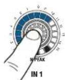
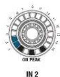
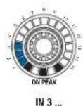
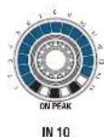
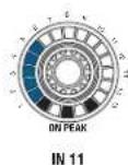
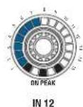
Figure 53: Select rotary knobs (source)
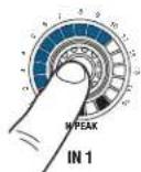
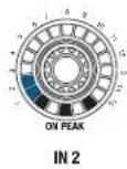
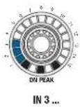
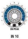
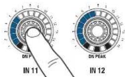
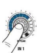
Figure 54: Define copy range (target)

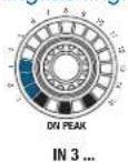
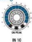
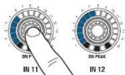
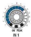
Figure 55: Keep the rotary knobs pressed down
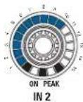
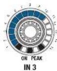
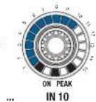

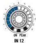
Figure 56: Complete copy process
Reset to factory settings
8.13 Resetting the factory settings
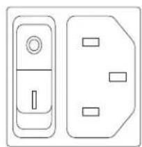

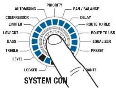
Figure 57: Resetting the factory settings
To reset the factory settings for the entire device, proceed as follows:
Step Description
1 Switch on the device
Wait until the start sequence of the automixer is complete (approx. 15 seconds).
2 Press the SYSTEM CONTROL rotary knob and keep pressed until step 5
3 Switch off the device at the mains
4 Switch the device back on after a short waiting time
Wait until the start sequence of the automixer is complete (approx. 15 seconds).
5 Release the SYSTEM CONTROL rotary knob
- The device's factory settings have now been restored and a new system configuration can now be set up.

Resetting the factory settings deletes all of the stored settings!
9 Troubleshooting

WARNING: Risk of electric shock
There are unprotected contacts and cables within the unit that could cause serious injury from electric shock on contact.
- The unit is only permitted to be opened by authorized, qualified personnel for troubleshooting purposes.
PROBLEM POSSIBLE CAUSE REMEDY
| No sound Power supply cable is not connected to unit | Connect power supply cable to unit |
| Power switch off Turn power switch to on position | |
| Device is not connected to amplifier Connect output channel to amplifier | |
| Microphone or auxiliary equipment not connected to unit | Connect microphone or auxiliary device to unit |
| Volume control set to minimum Turn up volume control | |
| Volume controls set to MUTE Cancel MUTE by pressing the rotary knob | |
| Pre-amplification not set correctly Set gain control on rear panel to correct pre-amplification | |
| Phantom power is switched off Switch on phantom power for condenser microphone | |
| External potentiometer set to minimum Turn up external potentiometer | |
| No sound with sinusoidal feed | Automix algorithm suppressing constant signal Exclude channel from automix algo-rithm |
PROBLEM POSSIBLE CAUSE REMEDY
Distorted signal reproduction
Pre-amplification not set correctly Set gain control on rear panel to correct pre-amplification
Volume control turned up too far Turn down volume
Input signal level too high Reduce input signal
If the error persists despite these instructions, contact AKG Acoustics GmbH or your AKG dealer immediately.
1 GENÉRALITÉS 134
5.2 Specifications techniques
Généralités
Généralités
Broche 1 = a
Broche 2 = b
Broche 3 =
Regulateur得益
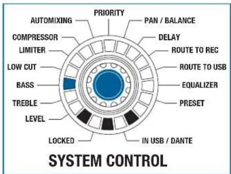
Illustration 23: Fonction BASS
8.9 Active ROUTING TO OUT
8.11 Activer/Désactiver LOCKED
| Editor | AKG Acoustics GmbH | AKG ACOUSTICS, U.S. |
| Laxenburger Straße 254 | 8500 Balboa Blvd. Dock 15 | |
| 1230 Viena | Northridge, CA 91329 | |
| Austria | U.S.A. | |
| Tfno.: +43 (0)1 86654-0 | Tfno.: +1 818 920-3224 | |
| Fax: +43 (0)1 86654-8800 | ||
| sales@akg.com | akgusatechsupport@harman.com | |
| Copyright | © 2015 AKG Acoustics GmbH | |
| Todo los derechos reservados. | ||
| La información contenido en este manual de instrucciones, asi como los dibujos y fotografías adjuntos, son propietad intelectual de AKG Acoustics GmbH. | ||
| En salvaguarda de los derechos de propietad intelectual no deben reproducirse ni comu- nicarse, total o parcialmente, esta documentación, con ningún fin, de ningún modo y por- ningún medio, ya sea electrónico o mecánico, mediante fotocopia, grabación o sistemas de - registro y reproducción de información, sin el permiso expresso por Escrito de la Empresa AKG Acoustics GmbH. Se prohibe toda transmisión a terceros. Si asi lo Solicitamos, deverá devolvermos este manual. | ||
| FCC Statement | Note: This equipment has been tested and found to comply with the limits for a Class B digital device, pursuant to part 15 of the FCC Rules. These limits are designed to provide reasonable protection against harmful interference in a residential installation. This equipment generates, uses and can radiate radio frequency energy and, if not installed and used in accordance with the instructions, may cause harmful interference to radio communications. However, there is no guarantee that interference will not occur in a particular installation. If this equipment does cause harmful interference to radio or television reception, which can be determined by turning the equipment off and on, the user is encouraged to try to correct the interference by one or more of the following measures:· Reorient or relocate the receiving antenna.· Increase the separation between the equipment and receiver.· Connect the equipment into an outlet on a circuit different from that to which the receiver is connected.· Consult the dealer or an experienced radio/TV technician for help. This device complies with Part 15 of the FCC Rules. Operation is subject to the following two conditions: (1) this device may not cause harmful interference, and (2) this device must accept any interference received, including interference that may cause undesired operation. Shielded cables and I/O cords must be used for this equipment to comply with the relevant FCC regulations. Changes or modifications not expressly approved by the party responsible for compliance could void the user's authority to operate this equipment. | |
| Actualización | Este manual pueda ser objerto de改动aciones sin previo作為, y no supone ninguna obligation para laEmpresa AKG Acoustics GmbH. | |
| Version 1.0 | ||
| Fecha de publicación | Julio de 2015/Alemania | |
1 Generalidades
1.1 Oberto del manual
Level
- Treble
Bass
Low cut
- Limiter
- Compressor
- Automixing
- Priority
Pan/Balance
Delay
- Routing To REC
- Routing To USB
Equalizer
- Preset
- Routing To Out 1
- Routing To Out 2
Monitoring
Mute
- Level
- Treble
Bass
Low cut - Compressor
- Automixing
- Priority
Pan - Routing To Out 1
- Routing To Out 2
- Routing To Rec
- Routing To USB
Monitoring
Mute
Level
- Treble
Bass
- Limiter
Balance
Delay
Equalizer
Monitoring
Mute
ERROR POSIBLE CAUSA SOLUCION
ERROR POSIBLE CAUSA SOLUCION
Reproduccion distorsionada de la seals

- SCOPE OF SUPPLY 71
- SAFETY AND ENVIRONMENT 72
- DECLARATION OF CONFORMITY 74
- DESCRIPTION 75
- INSTALLATION AND CONNECTION 89
- FUNCTIONAL DESCRIPTION 91
- General
- Purpose of the manual
- Retention of the manual
- Liability
- Liability
- Warranty
- Warranty
- Scope of supply
- Packing unit
- Packing unit
- Optional accessories
- Optional accessories
- Safety and environment
- Safety
- Safety
- Caution: Risk of damage
- Required knowledge and areas of responsibility of the operators/users
- Explanation of the symbols used
- Warning: Hazard due to electric shock
- Correct use
- Incorrect use
- Environment
- Declaration of Conformity
- Description
- Summary
- Summary
- Technical data
- General
- Front controls
- Front: Description of the controls
- No. Description
- Rotary knobs for inputs
- Controls for input channels
- LED ON
- LED PEAK
- SYSTEM CONTROL
- Operating mode / SYSTEM CONTROL
- Rotary knobs for outputs
- Control for stereo outputs
- Modulation display
- Modulation display for stereo outputs
- Headphone output
- Stereo headphone output
- Rear controls
- Rear: Description of the controls
- Input channels
- Inputs
- Gain controller
- Gain control
- Phantom power
- Phantom power
- Stereo output
- Stereo master bus output channel
- Stereo record output
- Stereo record output
- LAN port
- Expansion/cascading
- DanteTM network
- DanteTM network
- Algorithm for Automix
- Automix algorithm
- Level adjustment
- Dynamic level adjustment
- Best Mic On
- Best Mic On
- Noise Detect
- Noise Detect
- Expansion for cascading
- Expansion/cascading
- Installation and connection
- Installation
- Step Description
- Cascade devices (optional)
- Connecting microphones and accessories
- Connect to the mains power supply
- Functional description
- Control concept
- Rotary knob
- Operation of the rotary knobs
- Display of the audio level / VU function
- SYSTEM CONTROL
- SYSTEM CONTROL modes
- SYSTEM CONTROL functions
- Input channel modes
- Input channel modes
- Output channel modes
- Output channel modes
- Functions of the stereo headphone output (monitoring output)
- DSP functions
- DSP functions
- LEVEL
- LEVEL
- TREBLE
- LOW CUT
- LIMITER
- LIMITER
- COMPRESSOR
- COMPRESSOR
- AUTOMIXING
- AUTOMIXING
- PRIORITY
- PAN/BALANCE
- PAN/BALANCE
- ROUTING TO REC
- ROUTING TO USB
- EQUALIZER
- EQUALIZER
- PRESET
- PRESET
- Operating the device
- SYSTEM CONTROL: Changing parameters on the device
- Configuring microphones on the DMM14 U (UL, ULD)
- Monitoring the inputs/outputs
- Cascading devices
- Feed via USB and DanteTM
- Processing the feed
- Activating phantom power
- Using presets
- Selecting a preset
- Programming a preset
- Deleting a preset
- MUTE
- Using MUTE
- Activating MUTE
- Deactivating MUTE
- ROUTING TO OUT
- Activating ROUTING TO OUT
- For an input
- For multiple inputs
- Deactivating ROUTING TO OUT
- LOCKED
- Activate/deactivate LOCKED
- Lock rotary knob
- Locking the SYSTEM CONTROL rotary knob
- Unlock rotary knob
- Unlocking the SYSTEM CONTROL rotary knob
- Lock unit
- Locking the complete unit
- Unlock unit
- Unlocking the complete unit
- Unlock channels
- Unlocking individual channels
- Lock channels
- Locking individual channels
- Copying configuration data
- Copying individual values
- Copying all values
- Reset to factory settings
- Resetting the factory settings
- Troubleshooting
- WARNING: Risk of electric shock
- PROBLEM POSSIBLE CAUSE REMEDY
- GENÉRALITÉS 134
- Specifications techniques
- Généralités
- Regulateur得益
- Active ROUTING TO OUT
- Activer/Désactiver LOCKED
- Generalidades
- Oberto del manual
- ERROR POSIBLE CAUSA SOLUCION
Brand : AKG
Model : DMM14 ULD
Category : Hand blender