
LD670 - Label printer OKI - Free user manual and instructions
Find the device manual for free LD670 OKI in PDF.
| Product type | Direct thermal label printer |
| Brand | OKI |
| Model | LD670 |
| Print resolution | 8 dots/mm (0.125 mm) |
| Supported paper width | 25.4 to 83 mm (in 1 mm increments) |
| Maximum print speed (monochrome) | 260 mm/s (paper width ≥58 mm) |
| Maximum print speed (bichrome) | 115 mm/s |
| Print method | Direct thermal |
| Power supply | AC adapter 24 V DC / 1.5 A (input 100-240 V AC, 50/60 Hz) |
| Paper types | Plain paper, with black mark, pre-cut labels |
| Auto cutter | Yes (full or partial cut) |
| Interfaces | LAN (10/100), USB 1.1, RS-232C (depending on model) |
| Thermal head life | 150 km (monochrome) / 75 km (bichrome) |
| Cutter life | Up to 2 million cuts (receipt) |
| Operating temperature | 0 to 40 °C (guaranteed operation) |
| Operating humidity | 10 to 95% RH (non-condensing) |
| Recommended cleaning | Thermal head, platen roller, cutter blade, paper guide |
| Available option | Large paper roll unit (diameter up to 200 mm) |
Frequently Asked Questions - LD670 OKI
User questions about LD670 OKI
0 question about this device. Answer the ones you know or ask your own.
Ask a new question about this device
Download the instructions for your Label printer in PDF format for free! Find your manual LD670 - OKI and take your electronic device back in hand. On this page are published all the documents necessary for the use of your device. LD670 by OKI.
USER MANUAL LD670 OKI
Every effort has been made to ensure that the information in this document is complete, accurate, and up-to-date. The manufacturer assumes no responsibility for the results of errors beyond its control. The manufacturer also cannot guarantee that changes in software and equipment made by other manufacturers and referred to in this manual will not affect the applicability of the information in it. Mention of software products manufactured by other companies does not necessarily constitute endorsement by the manufacturer.
While all reasonable efforts have been made to make this document as accurate and helpful as possible, we make no warranty of any kind, expressed or implied, as to the accuracy or completeness of the information contained herein.
All rights are reserved by Oki Data Corporation. Unauthorized copying, transferring, translating, or related actions are prohibited. You must obtain written permission from Oki Data Corporation before doing any of the above.
© 2011 Oki Data Corporation
OKI is a registered trademark of Oki Electric Industry Co., Ltd.
Energy Star is a trademark of the United States Environmental Protection Agency.
Microsoft, Windows, Windows Server and Windows Vista are registered trademarks of Microsoft Corporation.
Apple, Macintosh, Rosetta, Mac and Mac OS are registered trademarks of Apple Inc.
Other product names and brand names are registered trademarks or trademarks of their proprietors.

As an Energy Star Program Participant, the manufacturer has determined that this product meets the Energy Star guidelines for energy efficiency.

This product complies with the requirements of the Council Directives 2014/30/EU (EMC) and 2014/35/EU (LVD), 2014/53/EU (RED) and 2011/65/EU(RoHS) as amended where applicable, on the approximation of the laws of the member states relating to Electromagnetic Compatibility, Low Voltage, Radio & Telecommunications Terminal Equipment, Energy related Products and Restriction on the use of certain Hazardous Substances in electrical and electronic equipment.
The following cables were used to evaluate this product to achieve EMC directive 2014/30/EU compliance and configurations other than this may affect that compliance.
| CABLE TYPE | LENGTH(METRE) | CORE SHIELD | |
| Power 2.0 | × | × | |
| USB 5.0 | × | √ | |
| Serial (25pin) | 15.0 | × | √ |
| LAN | 10.0 | × | × |
| Drawer 1.8 | × | × | |
WARNING! This is a class A product as defined in EN55022. In a domestic environment this product may cause radio interference, in which case the user may be required to take adequate measures.
MANUFACTURER
Oki Data Corporation,
4-11-22 Shibaura, Minato-ku,
Tokyo 108-8551,
Japan
For all sales, support and general enquiries contact your local distributor.
IMPORTER TO THE EU/AUTHORISED REPRESENTATIVE
OKI Europe Limited (trading as OKI Printing Solutions)
Blays House
Wick Road
Egham
Surrey, TW20 0HJ
United Kingdom
For all sales, support and general enquiries contact your local distributor.
ENVIRONMENTAL INFORMATION

Description of Safety symbols displayed on the equipment
| No. | Symbol Description | |
| 1 | [TXV8] | "ON" (power)To indicate connection to the mains, at least for mains switches or their positions. |
| 2 |  | Stand-byTo identify the switch or switch position by means of which part of the equipment is switched on in order to bring it into the stand-by condition. |
| 3 |  | General warning/cautionTo identify a general warning/caution. |
| 4 |  | Caution, hot surfaceTo indicate that the marked item can be hot and should not be touched without taking care. |
| 5 |  | Direct currentTo indicate on the rating plate that the equipment is suitable for direct current only; to identify relevant terminals. |
| 6 | [SHC] | Alternating currentTo indicate on the rating plate that the equipment is suitable for alternating current only; to identify relevant terminals. |
Notes on Use
Notes on printing and the paper used
(1) Printing at a high rate might result in unclear printing. If this problem occurs, adjust the printing rate. Alternatively, adjust the print speed and print density so that there are no blurs.
(See Examples (1) and (2) in Section 10-2, "Setting Up the Printer.")
(2) Printing characters from a non-standard character set e.g. in a thin serif font will result in the characters appearing very faint. Use a bold sans serif font.
(3) For quality printing that is free from uneven spacing and condensed or elongated printing after paper is cut or printing is paused, resume printing following a paper feed of at least 1 mm (8 dots).
(4) If the data transfer rate is too low, serial printing may result in uneven print density (vertical white marks may appear on printouts) because of repeated printing and pausing. If priority is placed on print quality, use batch printing mode.
(See Example (8) in Section 10-2, "Setting Up the Printer.")
(5) The printer shipped from the factory is preset to the darkest print density (130%). If this setting is inappropriate, specify a lighter print density.
(See Example (1) in Section 10-2, "Setting Up the Printer.")
(6) If roll paper with an outside core diameter of other than 32 mm is used, the paper-near-end detection accuracy deteriorates.
If roll paper with an outside core diameter of less than 32 mm is used, a transport error may occur when the cutter cuts the paper in full cutting mode and reaches the core.
(7) Since the difference in hue between red and black or blue and black may not be noticeable when two-color thermal paper is used, be sure to confirm in advance the color of the printed characters.
(8) When roll paper with a width of 83 mm is used, characters that are too close to the (left or right) edge of the paper may not be printed because of inaccuracies in tracking. Be sure to set a margin of sufficient width.
(9) Do not switch from narrow paper to wide paper (e.g., from paper that is 58 mm wide to paper that is 80 mm wide) during operation. When narrow paper is used, the thermal head area where there is no paper comes in direct contact with the platen roller, and the resulting wear on the head may lead to a deterioration in print quality. Similarly, if the paper width is changed, the cutter blade will cut at a location that has no paper, and the resulting wear on the blade may lead to improper cuts. To switch from narrow paper to wide paper, exchange the thermal head and the cutter blade.
(10) If label paper is used, adhesive matter adhering to the cutter blade, thermal head, paper transport, or paper holder may cause a cutting error, print error, or paper transport error. Remove adhesive matter periodically (typically on a monthly basis).
(11) If paper is left inserted in the printer for a long time, the paper may become deformed and result in thin (faint) printed characters. Before starting printing in such cases, feed the paper by 20 to 30 mm.
(12) If the type of paper used is other than the recommended ones, the print quality and thermal head life are not guaranteed. In particular, if the type of thermal paper contains Na+, K+, or Cl-, the thermal head life may be significantly shortened.
(13) When using full-sheet label paper, note that the paper may adhere to the head and cause noise if the top margin is less than 3 mm. You should therefore set the top margin to 3 mm or a greater value when printing on this type of paper.
Notes on using the cutter
(1) Note also that the paper length used per transaction must be at least 15mm.
(2) The maximum number of successive cuts by the cutter is 30 cuts per minute (at least two seconds per cut). Using the cutter at a higher rate may cause a failure.
(3) Do not pull the paper during cutting. Doing so may cause a paper jam or another problem.
(4) Each time that 30 sheets of paper are printed, the paper must be removed. Otherwise, the printed paper remains in the automatic cutter section and may cause a cutting error.
Notes on printing of barcodes and two-dimensional codes
(1) Barcodes that are rotated 90 degrees or aligned vertically when printed may not be readable. Verify the readability in advance.
(2) Printouts on label paper or thick paper may contain blurs, depending on humidity and other environmental conditions. Adjust the print speed and print density appropriate for the type of paper used, and verify the readability in advance.
(See Examples (1) and (2) in Section 10-2. "Setting Up the Printer.")
(3) The recognition ratio of two-dimensional codes (QR codes, PDF417, DataMatrix, MaxiCode and RSS) varies depending on various factors, including the module width, print density, ambient temperature, thermal roll paper type, and reader performance. Adjust the print speed and print density appropriate to printing two-dimensional codes, and verify the readability in advance.
(See Examples (1) and (2) in Section 10-2, "Setting Up the Printer.")
(4) The paper transport accuracy may be negatively affected by printing a barcode in the Upper margin at the beginning of paper transport or in the Lower margin at the end of paper transport. Verify the readability before starting printing.
Notes on using the printer through the USB interface
(1) The printer must be connected directly to the host computer.
(2) Before starting printing, turn on the power to the printer.
(3) If a printer error occurs during printing, recover the printer from the error, and then retry printing.
(4) The host computer should not be set to any of the following modes: standby, sleep, suspend, and pause.
If the host computer or printer does not work normally after the host computer returns to normal operation mode from one of the above modes, disconnect the USB cable once and then reconnect it, or turn off the printer power switch once and then turn on the switch again. If the host computer or printer cannot be restored to normal operation after the cable is reconnected or power switch is turned on again, restart the host computer.
(5) The USB hub function cannot be used when the power to the printer is off.
(6) If a peripheral device connected to the USB hub is not recognized, perform one of the following operations:
- Disconnect the USB cable from the peripheral device once, and then reconnect it.
- Connect the peripheral device to the other port of the USB hub.
(7) The operation of connected USB devices is not guaranteed. Before using a USB device, verify its operation yourself.
Note : Do not turn off the power to the printer during printing.
If you inadvertently turn off the power to the printer during printing and the printer then fails to work normally, restart the host computer.
Note on installation
(1) The printer must be used indoors. If used outdoors, the printer may fail because of dust.
Note on the modular connector
(1) This product uses a modular connector as a dedicated connector for the cash drawer or customer display terminal. The connector must not be connected with a connector that leads to a public switched line or other such destination.
Note on using the printer in special mode
(1) If a large diameter roll is used, paper may fold or unusual noises may be heard. To prevent these problems, use a roll with a small diameter ( 50mm or less). If a Windows PC is used as the host system, a utility program can be used to make settings.
Windows® is a registered trademark of Microsoft Corporation in the United States and/or other countries.
TABLE OF CONTENTS
- Appearance and Names of Components 11
Appended goods 12
- AC Adapter 13
2-1. AC adapter 13
- Paper Specifications 14
3-1. Paper Width 14
3-2. Paper Thickness 14
3-3. Forms of Paper 14
3-4. Paper Types 16
3-4-1. Requirements for full-sheet label paper 18
3-4-2. Conditions for using black mark paper 19
3-4-3. Conditions for using die-cut label paper 20
3-5. Recommended Thermal Paper 21
- Preparations 23
4-1. Connecting Interface Cable 23
4-2. Connecting the drawer kick cable 26
4-3. Connecting the AC Adapter 27
4-4. Disconnecting the AC Adapter 29
4-5. Turning on the Power 30
- Inserting Paper for Printing 31
5-1. Opening the Top Cover 31
5-2. Setting the Paper Width 32
5-2-1. Mounting separator A 33
5-2-2. Removing separators A and B 34
5-2-3. Attaching separators A and B 36
5-3. Loading Paper 38
5-3-1. Loading roll paper 38
5-3-2. Loading fanfold paper 40
5-4. Setting the Paper Guide 43
5-5. Closing the Top Cover 44
- Setting Up the Printer 45
6-1. Paper Information Setting Using the Driver 47
6-1-1. Paper layout 48
6-1-2. Custom paper 49
6-1-3. Printing from an application 53
6-2. Paper information setting using the utility 54
6-2-1. Paper layout 54
6-2-2. Setting detailed paper layout information 55
6-3. Setting Paper Information Using the Printer 58
6-3-1. Automatic layout detection 58
6-3-2. Setting the Paper Width 59
6-3-3. Automatic layout detection 61
6-4. Replacing paper 64
6-5. Paper Layout Errors 65
6-6. Adjusting Sensors 66
6-7. Print Density Setting 67
6-8. Print Speed Setting 68
6-9. Cutting Position Correction 69
6-10. Other Settings 70
6-11. Initializing the Printer Setup Information 70
- Control Panel 71
7-1. Control Panel 71
7-2. Error Indications 73
- Preventing and Clearing Paper Jams 75
8-1. Preventing Paper Jams 75
8-2. Clearing a Paper Jam 75
- Troubleshooting 76
9-1. Power-on Problems and Errors 76
9-2. Cutter-related Problems 76
9-3. Printing-related Problems 77
- Special Modes 78
10-1. Test Printing 78
10-2. Setting Up the Printer 80
Example (1): Changing the Print Density 81
Example (2): Changing the Max Speed 89
Example (3): Changing the Print Color 97
Example (4) Changing the Feed at Power On 104
Example (5) Initializing the printer settings 112
Example (6) Changing the PNE Detect 116
Example (7) Changing the Paper Width 125
Example (8) Changing the Batch(OTHER IF) 133
10-3. Setup Items 142
10-4. Sensor Adjustment 151
10-4-1. Sensor adjustment mode 151
10-4-2. Black mark (BM) sensor adjustment 156
10-4-3. Adjusting the label sensor 158
10-4-4. Paper-near-end (PNE) sensor adjustment 160
10-4-5. Paper end (PE) sensor adjustment 162
10-5. Data Analysis 165
10-6. Sample Print 169
11. Regular Cleaning 174
11-1. Cleaning the Paper Holder and Paper Transport 174
11-2. Cleaning the Platen Roller 175
11-3. Cleaning the Thermal Head 179
11-4. Cleaning the Cutter Blade and Frame 180
12. Interface 188
12-1. LAN Interface 188
12-2. Dual Interface 190
12-3. Drawer Kick Connector 191
12-4. Specifications of Power Supply 194
13. Specifications 195
13-1. General Specifications 195
13-2. Cutter Specifications 199
13-3. Paper Supply Specifications 200
13-4. Interface Specifications 201
13-5. Environment Specifications 202
13-6. Specifications of Reliability 203
14. Roll Paper Unit 204
14-1. Outline 204
14-2. Nomenclature 204
14-3. Paper Specifications 206
14-4. Roll Paper Feed Specifications 207
14-5. Roll Paper Unit Installation Procedure 208
14-6. Method of setting PNE sensor 213
14-7. Method of setting guide plate 214
14-8. Setting the Roll Paper 215
14-9. Roll Paper Unit Appearance 220
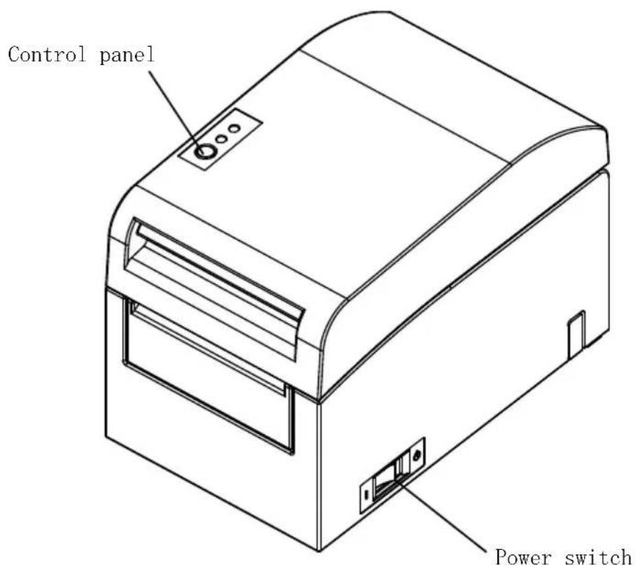
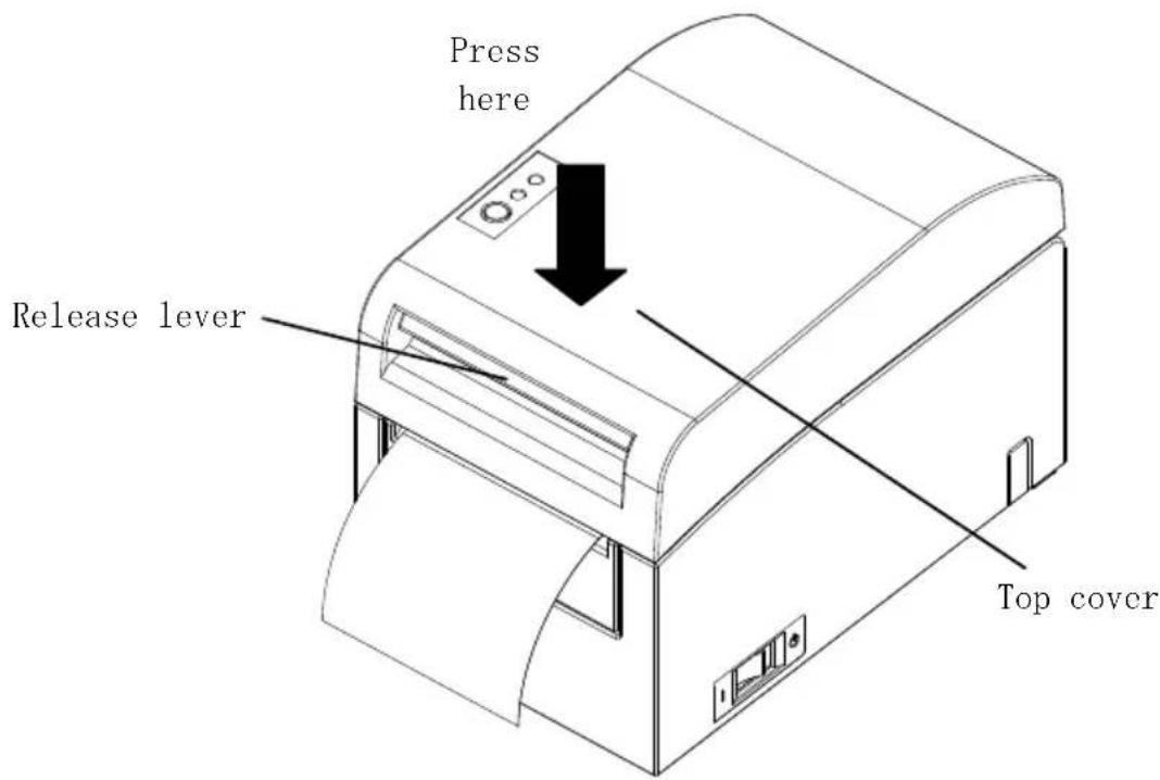
1. Appearance and Names of Components
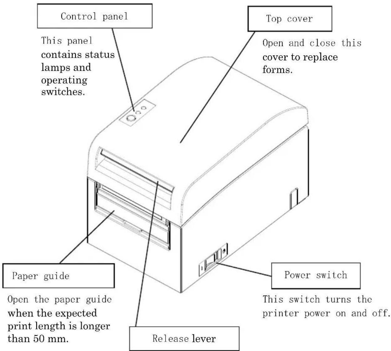
Pull up the release lever to open the top cover.
Appended goods
Thermal paper CD
natural_image
Simple geometric diagram with concentric circles and a diagonal line inside a diamond shape (no text or symbols)MANUAL
PRINTER DRIVER
UTILITY SOFT

natural_image
Simple geometric diamond shape outline with no text or symbolsInstruction sheet Safety warranty sheet

natural_image
Simple geometric diamond shape outline with no text or symbols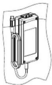
natural_image
Technical line drawing of a mechanical device with a curved arm and housing (no text or symbols)AC adapter Power cable
2. AC Adapter
2-1. AC adapter
Only use the AC adapter specified below.
Model name: KA02951-0120
Input: 100 to 240V AC, 50/60Hz-
Output: DC24V±5%, 1.5A
Caution: Only use authorized AC adapters.
⚠ Caution: Do not use the bundled AC adapter and Power cable for any electrical equipment other than this printer.
3. Paper Specifications
3-1. Paper Width
(1) Paper width of 83 mm: 83^0-1.0 mm; paper width of 80 mm: 80^0-1.0 mm
(2) Paper width within a range of 70 to 25.4mm (by units of 1mm )
: 70 to 25.4 ^0 -1.0 mm
Note: Paper with a width within a range of 71 to 79 mm cannot be used.
3-2. Paper Thickness
: 75 to 150 μm
3-3. Forms of Paper
(1) Roll paper
- Outside diameter: 102±0.5 mm or less
With the large-diameter roll paper unit (option) attached, the printer can use a roll with an outside diameter of up to 200 mm. - Core dimension: Inside diameter of 1 inch
(inside diameter: 25.4 ± 0.5 mm; outside diameter: 32 ± 0.5 mm) - Printed surface: Outside of the roll
- Treatment of end of paper: The roll paper must not be glued to the core.
The end of the paper must also not be folded back.
Note: Do not use rolls that have rough sides or sides from which pieces of paper extrude. Using such rolls could cause a printer failure.
(2) Fanfold paper
- Maximum stack height: 180 mm or less
- Fold length: 76.2 to 203.2 ± 0.5 ~mm (3 to 8 inches)
- Perforation specifications: 3 (cuts):1 (tie)
3-4. Paper Types
The printer supports the following paper types:
a. Plain paper (including full-sheet label paper)
b. Black mark paper
c. Die-cut label paper (including die-cut label paper with black marks)
When using black mark or die-cut paper, the printer can move the paper to the start position, cutting position, peeling-off position, or tear-off position according to the paper layout settings.
To use this function, provide the printer with paper layout information, including the paper type and size, before printing. Use of the printer without these settings may result in a paper layout error or unexpected printouts.
Therefore, set the paper layout when you:
(1) use label paper for the first time,
(2) change the paper type (plain paper, black mark paper, or die-cut label paper),
(3) change the paper size, or
(4) switch to die-cut label paper of the same size as the current paper but with a different base color or other specification.
You can set the paper layout automatically or manually. For details, see Chapter 6, "Setting Up the Printer."
Note: Die-cut label paper is a type of label paper with a label sheet already cut into segments of a certain size.
Note: Full-sheet label paper is a type of label paper with an uncut label sheet that allows users to cut to any length by using a cutter.
Note: The same settings can be used when printing on full-sheet label paper or plain paper (with no black marks).
Note: When printing on die-cut label paper with black marks, be careful regarding the print position and cut position. Printing on base paper, which is not covered with label sheet, may damage the thermal head.
Note: Note on preprinting on the recording side of thermal paper Using thermal paper whose recording side is preprinted may result in the thermal head sticking to the surface of thermal paper, causing a print error. Therefore, you should avoid using this type of thermal paper as much as possible. If such use is unavoidable, confirm beforehand that use of the paper does not cause print errors, thin printing or other problems.
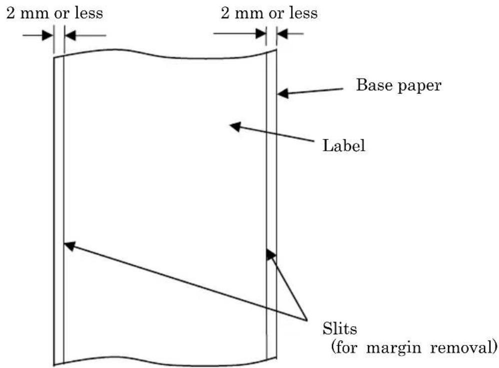
3-4-1. Requirements for full-sheet label paper
To prevent adhesive matter from sticking to the print head or paper guide, use label paper that has undergone margin removal as shown below.
(Margin removal means cutting the margins at the time of manufacturing.)
Slits on both sides on the printable side of paper
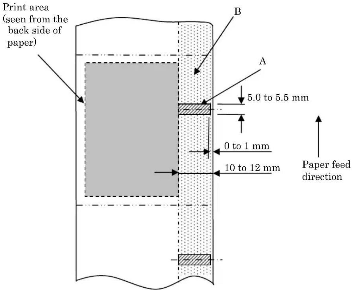
3-4-2. Conditions for using black mark paper
When using receipt paper or full-sheet label paper with black marks, confirm that the following conditions are satisfied. The reflection factors at locations A and B on the paper must be the combination of values specified in the table below.
| Reflection | |
| A: Black mark area 8% | |
| B: Margins above or below black marks 75% |
Note: The reflectivity values were measured using a Macbeth PCM II density meter (Filter C).
Back side of paper
(back of the coloring side of paper)
3-4-3. Conditions for using die-cut label paper
When using die-cut label paper, confirm that the following conditions are satisfied. When using die-cut label paper with black marks, confirm that the conditions stated in Section 3-4-2, "Conditions for using black mark paper," are also satisfied.
Printable side of paper
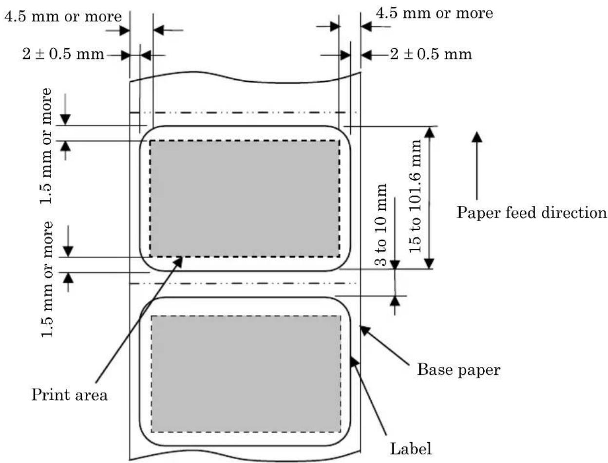
Note: The base paper's opacity (ISO) must be equal to or less than 70%.
3-5. Recommended Thermal Paper
| Manufacturer | Product name | Quality characteristics Paper | thickness | Density specification |
| Ltd. | PD160R Monochrome receipt paper (high-grade preservation type) | 75μm | 100% Oji Paper Co | |
| PD190R Monochrome receipt paper (mid-grade preservation type) | 75μm | 100% | ||
| Nippon Paper Industries Co., Ltd. | TF60KS-EX Monochrome receipt paper (normal type) | 75μm | 100% | |
| TP60KS-FN Monochrome receipt paper (mid-grade preservation type) | 75μm | 100% | ||
| HD75 Monochrome label paper (normal type) | 150μm | 130% | ||
| Mitsubishi Paper Mills Limited | P220AE-1 Monochrome thick paper (normal type) | 150μm | 100% | |
| PB670 Two-color thermal paper (red/black: normal type) | 75μm | 105% | ||
| PB770 Two-color thermal paper (blue/black: normal type) | 75μm | 100% | ||
| Ricoh Co., Ltd. | 150LHB Monochrome label paper (high-grade preservation type) | 150μm | 130% | |
Note : A recommended type of paper must be used. If a type of paper other than a recommended one is used, head damage, printing irregularities, or similar problems may occur.
Note : To use two-color thermal paper, set the print color to two colors from the printer setup menu or using the setup tool contained on the CD-ROM provided with the printer.
(See Example (3) in Section 10-2, "Setting Up the Printer.")
* By setting the appropriate property (use Color on the Graphics tab) for printing with this printer driver, you can easily print in two-color mode without having to change the printer setup.
Note : Ruled lines or characters containing fine lines (e.g. a serif typeface) tend to have dull colors when they are printed on two-color thermal paper. For printing on two-color thermal paper, a thick font (e.g., a sans serif font) is recommended.
Note : Red or blue printing on two-color thermal paper has an inferior preservation characteristic that is equivalent to that of normal thermal paper.
Note : Printouts on label paper or thick paper may contain blurs or voids, depending on the humidity and other environmental conditions.
Adjust the print speed and print density as appropriate for the type of paper used.
(See Examples (1) and (2) in Section 10-2, "Setting Up the Printer.")
In particular, note that the paper transport accuracy may be negatively affected by printing a barcode in the top margin at the beginning of paper transport or in the Lower margin at the end of paper transport.
Note : The outside core diameter is assumed to be 32 mm.
If roll paper with an outside core diameter of other than 32 mm is used, the paper-near-end detection accuracy deteriorates.
Note : If roll paper with an outside core diameter of less than 32 mm is used, a transport error may occur when the cutter cuts the paper in full cutting mode and reaches the core.
4. Preparations
No printer cable is provided with the product. Obtain a printer cable suitable for the product interface. If you have any questions, consult your dealer. Before connecting or disconnecting cables, make sure of the following:
1) The power to the printer and all other devices connected to the printer is turned off.
2) The AC adapter power cable has been unplugged from the outlet.
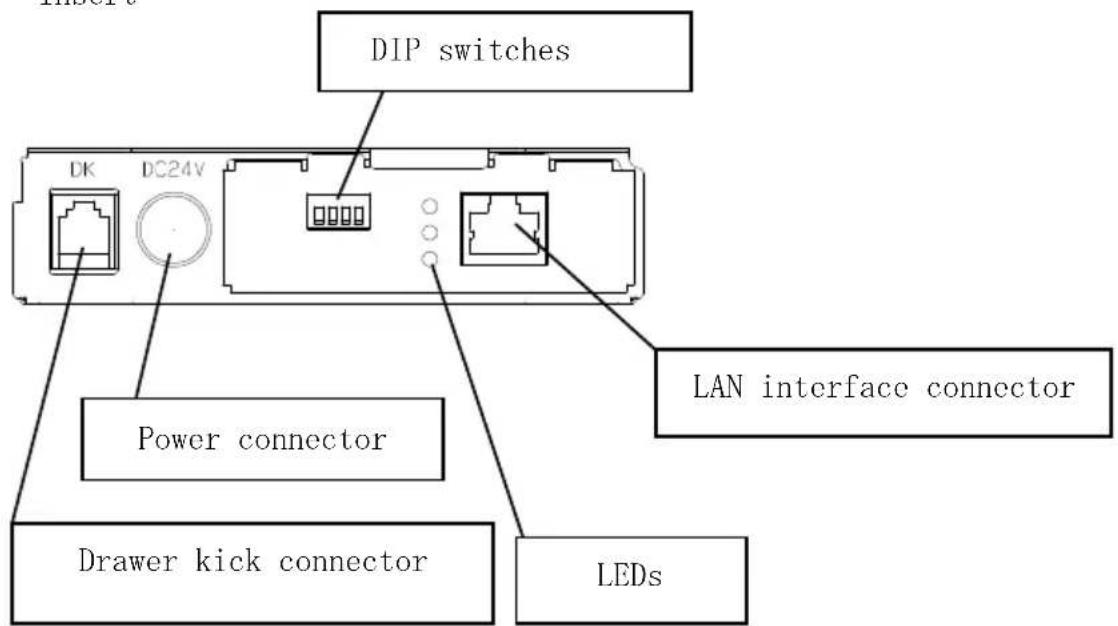
4-1. Connecting Interface Cable
Open the connector cover at the rear of the printer by pulling it up, and connect the interface cable to its rear connector socket. Close the cover after connecting the cable.
Note: If cables are arranged so that they extend from the rear or from the rear on the right side, remove the inserts in the connector cover or the cover with nippers or a similar tool. Unless the inserts are removed in this case, the cables may be damaged and cause a failure.
LAN interface model
Connector Cover
Insert
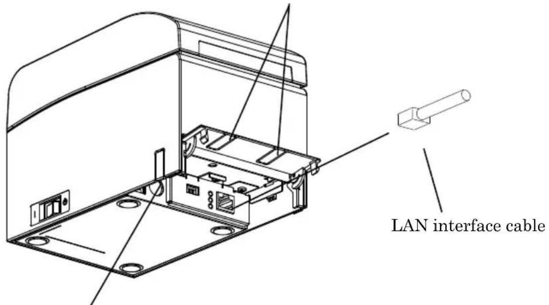
Insert
Caution: Do not touch the DIP switches during normal use. This may change the network settings, disabling normal printing.
Caution: If the device is installed vertically, the LAN cable may not usable due to its shape. Please check before installing.
⚠ Caution: The LAN interface cable must use the shield type.
For a unit with Dual interface
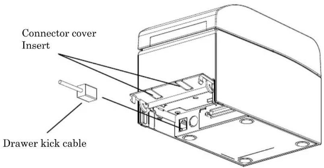
4-2. Connecting the drawer kick cable
Open the connector cover at the rear of the printer by pulling it up, and connect the drawer kick cable to its rear connector socket. Close the cover after connecting the cable.
Note : If the cable is arranged so that it extends from the rear, remove the inserts in the connector cover with nippers or a similar tool. Unless the inserts are removed in this case, the cable may be damaged and cause a failure.
Note: The drawer kick cable must not be used for a purpose other than for control of the drawer.
4-3. Connecting the AC Adapter
(1) Connect the AC adapter to the AC adapter power cable.
Note: To connect or disconnect the AC adapter, turn off the power switches of the printer and all the devices to be connected to the printer. Then, unplug the plug of the AC adapter power cable from the electrical outlet.
Note: Use only the specified AC adapter and specified AC adapter power cable.
(2) Open the connector cover at the rear of the printer by pulling it up, and connect the AC adapter cable to the power socket. Close the cover after connecting the cable.
Note: To connect the AC adaptor, place the printer on its side to make the connection operation easier to perform.
Note: Remove notch of connector cover with Nipper, to maintain the space for the cable of AC adapter. Otherwise, the cable may be damaged and it way cause a failure.
natural_image
Technical line drawing of an open electronic device casing with internal components (no text or symbols)Printer placed on its side
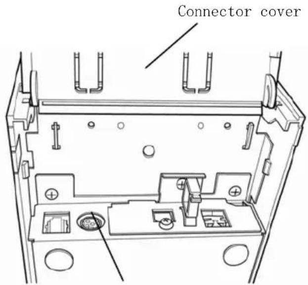
Power connector
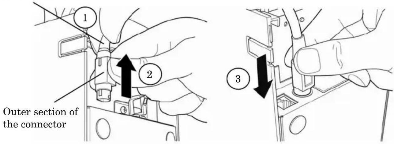
Note: To prevent the adaptor from slipping out, the connector section is designed to be tight to fit. When inserting, (1) pinch the base of the cable, (2) while sliding the outer section of the connector upwards, (3) and insert the connector until it locks in place with a “click” sound.
Base of the cable
(3) Connect the plug of the power cable to electrical outlet.
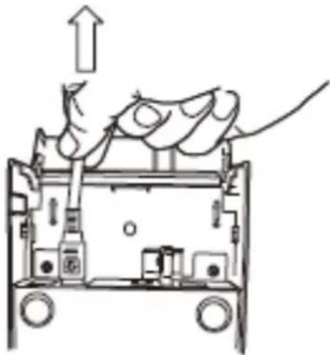
natural_image
Diagram of a mechanical device with an upward arrow and internal components (no text or symbols)(4) Plug the other end of the power cord into the power outlet.
4-4. Disconnecting the AC Adapter
To unplug the AC adapter cable, grasp the connector as shown in the picture below and pull it out. The lock mechanism of the connector will then disengage, and the cable can be unplugged easily. Conversely, forcibly pulling on the cable itself may damage the connector.
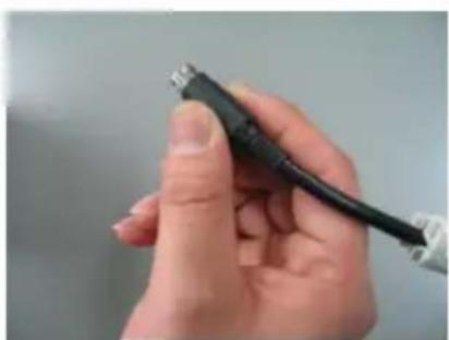
natural_image
Close-up of a hand holding a black USB cable (no text or symbols visible)
natural_image
Hand inserting a black cable into a white electronic device casing (no text or symbols visible)Note: Before disconnecting the AC adapter, switch off the printer and all devices connected to the printer, and also disconnect the power cable of the AC adapter from the outlet.
4-5. Turning on the Power
After the AC adapter is connected, turn on the power switch at the side of the printer. The POWER lamp on the control panel lights.
5. Inserting Paper for Printing
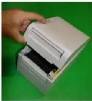
5-1. Opening the Top Cover
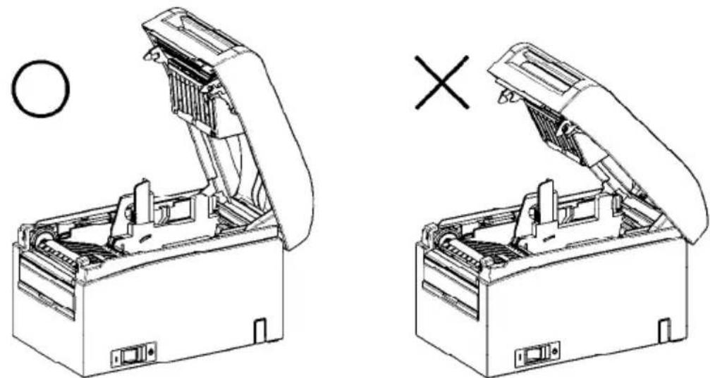
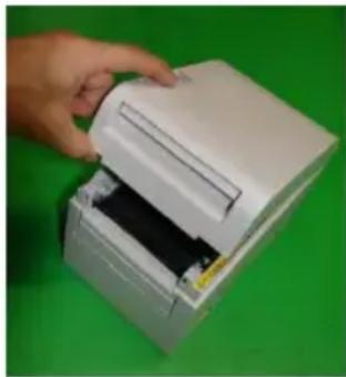
(1) Grasp the top cover, pull up the cover release lever, and open the top cover.
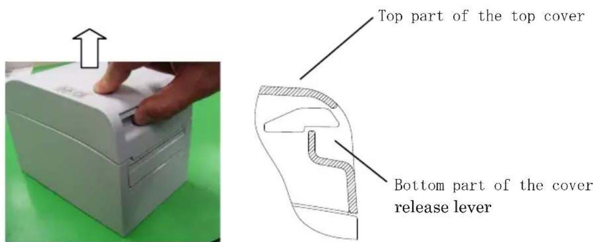
(2) When manipulating the top cover, note that the cover seems to lock in position before it is open completely. Make sure that the cover is really open completely as shown in the picture below.
natural_image
Technical line drawing of two open mechanical devices with internal components, one open and one closed, showing no text or symbols.Note: If the top cover is not open completely during maintenance, it may close inadvertently.
5-2. Setting the Paper Width
Separator A is set to the position for a paper width of 70 mm at the time of shipment from the factory.
- By adjusting the position of separator A, you can use paper with a width within a range of 70 to 25.4 ~mm . (See "Section 5-2-1. Attaching separator A.")
- To use paper with a width of 80 mm, remove separator A.
(See "Section 5-2-2. Removing separators A and B.")
- To use paper with a width of 83 mm, remove separators A and B.
(See "Section 5-2-2. Removing separators A and B.")
Note : When replacing the separator, set a paper width appropriate to the print area, referring to "Special Modes."
(See Examples (7) in Section 10-2, "Setting Up the Printer.")
Note: If the printer is using narrow paper (e.g., width of 70 mm), do not replace the paper with wide paper (e.g., width of 80 mm). In printing with narrow paper, part of the thermal head (the part where there is no paper) comes in direct contact with the platen roller. The resulting wear may lead to a deterioration in print quality. Similarly, if the paper width is changed such that the cutter blade cuts at a location that has no paper, the resulting wear on the blade may lead to improper cuts.
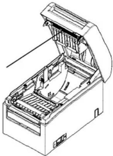
Note : Do not touch the thermal head except during cleaning. Doing so may result in damage from static electricity.
Thermal head
natural_image
Technical line drawing of an open industrial machine with internal components (no text or symbols)5-2-1. Mounting separator A
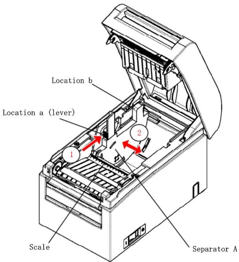
Holding separator A at locations a (lever) and b, slide the lever to the desired position. Then, set the separator in place. Use the scale as necessary.
Note: Separator A must be set in place with an allowance of about 0.5 mm for the maximum paper width.
5-2-2. Removing separators A and B
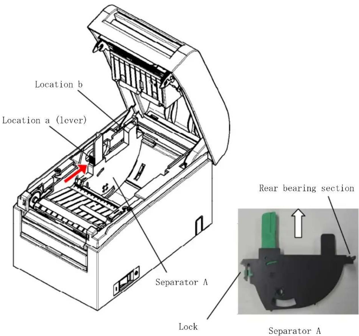
(1) Removing separator A
While holding part b on separator A with part a (lever) pushed in the arrow-indicated direction, lift it to disengage the lock, and then remove the rear bearing section.
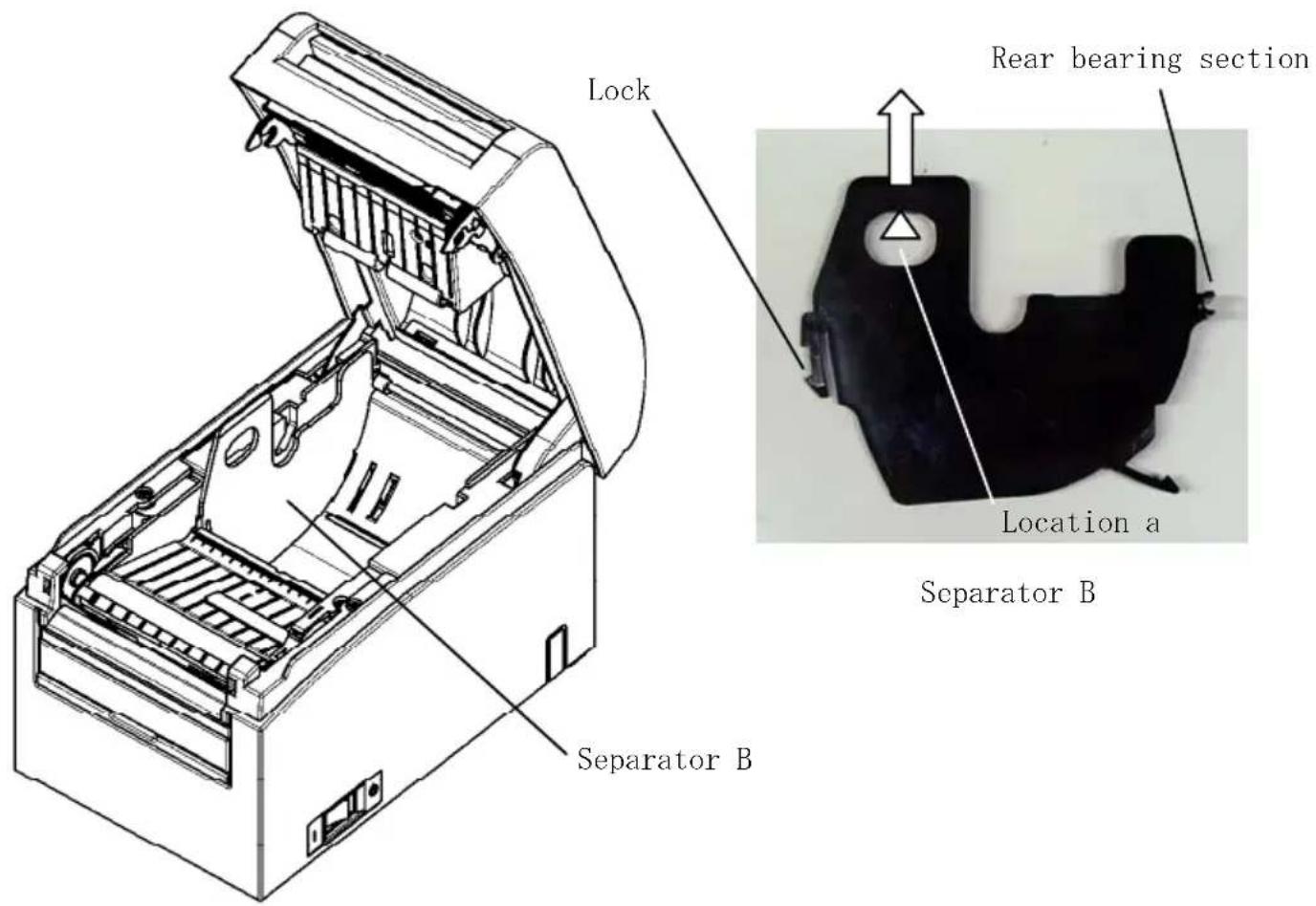
(2) Removing separator B
Holding separator B at location a, lift the separator to disengage the lock. Then, remove the separator at the rear bearing section.
5-2-3. Attaching separators A and B
(1) Attaching separator A
Attach separator A from the rear bearing section.
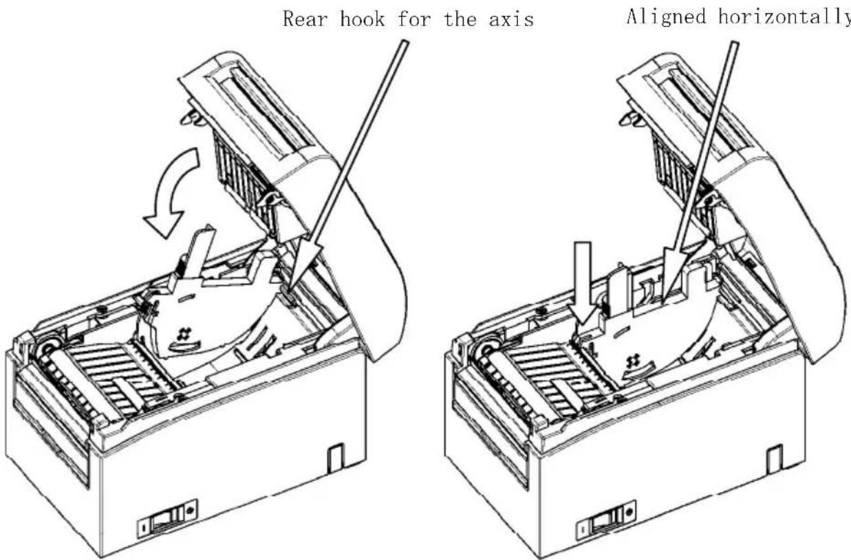
Note : Push the separator down until it engages with an audible click, and confirm that the top of the separator is aligned horizontally.
(2) Attaching separator B
Attach separator B from the rear bearing section.
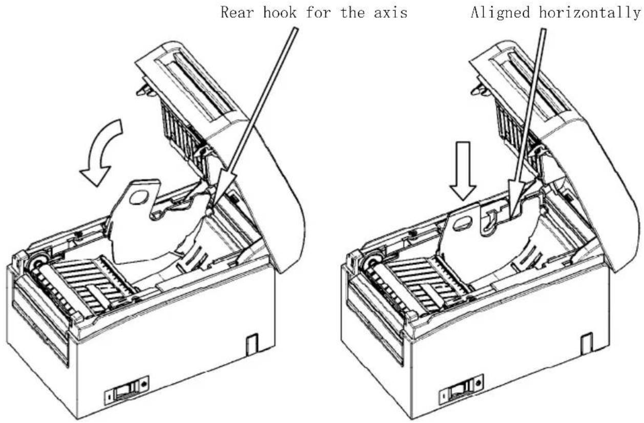
Note : Push the separator down until it engages with an audible click, and confirm that the top of the separator is aligned horizontally.
5-3. Loading Paper
5-3-1. Loading roll paper
(1) When using a new paper roll, remove the glued portion of the paper as well as the part to which adhesive tape is affixed.
Note : Since the glued portion of the paper should not be printed on, remove about one turn (about 40 cm) of the roll paper from the beginning so that none of the remaining paper has glue on it.
Any adhesive or other matter remaining from the glue may adhere to the thermal head and cause a problem, such as voids on printouts. Therefore, do not forget to remove the glued portion of the paper.
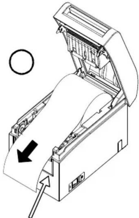
(2) From the front of the printer, pull out the end of the paper as shown below.
natural_image
Technical line drawing of a mechanical device with an open lid and internal components, showing a circular arrow indicating direction (no text or symbols present)Front cover of the printer.
Note: Pull the end of roll paper until it comes out from the front of the cover.
Note : Before loading a new roll, make sure that an old core does not remain in the roll holder. Leaving an old core will cause a paper-near-end error condition.
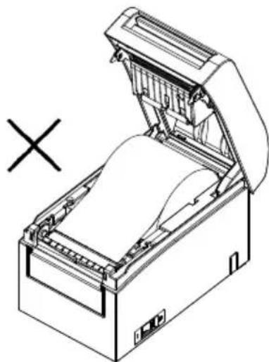
natural_image
Line drawing of a mechanical device with an open lid and internal components, no text or symbols present.Paper not protruding from the front cover
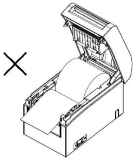
natural_image
Technical line drawing of an open industrial machine with a cross symbol indicating cancellation (no text or labels present)Roll paper inserted upside down
Note : The roll paper must have no deformities. Using roll paper such as that shown in the figure below may cause a paper jam, uneven printing, or other printing problem.
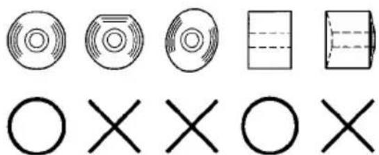
natural_image
Pure geometric shapes including circles, rectangles, and crosses without any text or symbolsNote : If the loaded roll paper is loose (slack) as shown below, take up the slack before printing on the paper. Printing on roll paper that is loose may cause a paper jam, uneven printing, or other printing problem, which will prevent the printer from detecting paper near end conditions.
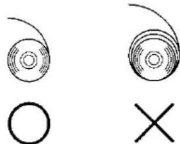
natural_image
Two abstract circular patterns with a circle and an 'X' symbol, no text or labels present.5-3-2. Loading fanfold paper
(1) Load the fanfold paper with its thermo sensitive side facing up.
(2) Open the top cover, and then pass the fanfold paper through the paper feed section at the rear of the printer.
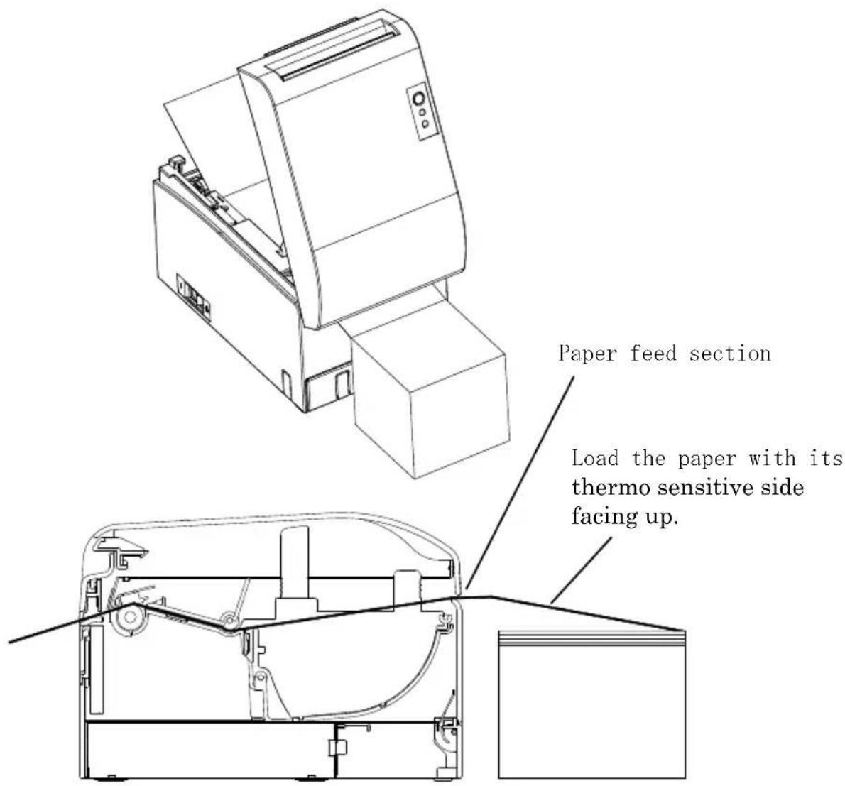
Note: Pull the end of fanfold paper until it comes out from the front of the cover.
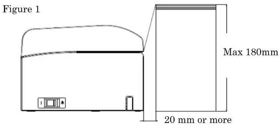
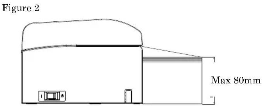
Note: Fanfold paper must be placed at least 20 mm from the rear of the printer. When this requirement is satisfied, paper can be stacked up to 180 mm (see Figure 1).
When fanfold paper is placed in contact with the rear of the printer, paper can only be stacked up to 80 mm (see Figure 2).
Note: Also, the paper location must be confined to an area between the left and right edges of the printer.
Note: When using perforated paper, make sure that the printer does not cut the paper at perforations or in an area that is 0 to 15 mm in front of perforations (as viewed from the paper feed direction). Otherwise, incorrect cutting may result. (See Figure 3.)
Note: When using perforated paper, be sure to prevent paper from being caught, paper jams, paper from being cut during transport, and other such problems. These problems may shorten the life of the thermal head.
Area that is 0 to 15 mm in front of perforations (cutting prohibited in this area)
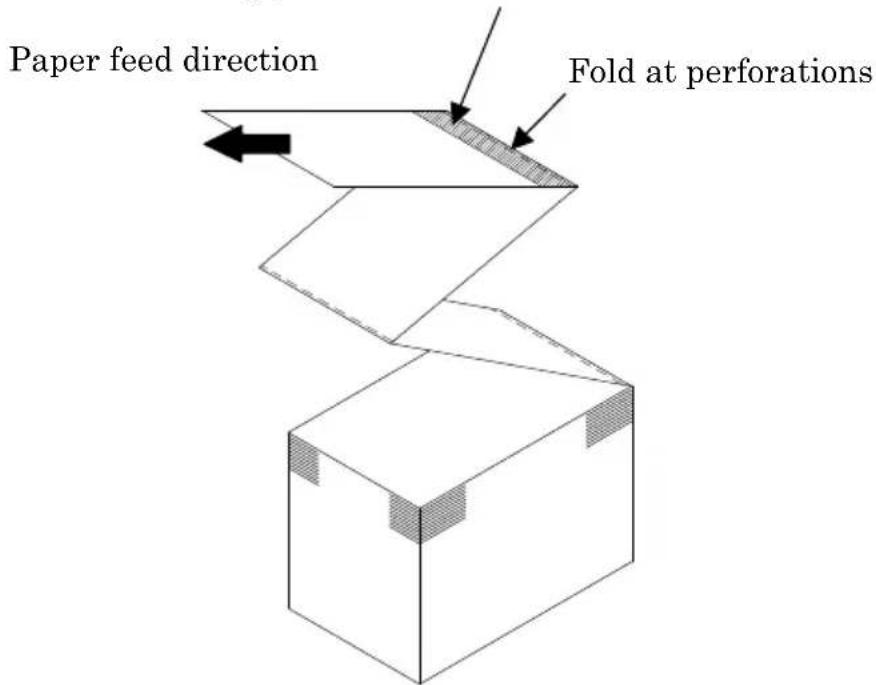
Figure 3
Note: Should you find that the blinking ERROR lamp annoys you, perform printer setup to change PNE DETECT to DISABLE. (See Example (6) in Section 10-2, "Setting Up the Printer.")
5-4. Setting the Paper Guide
When the print length per print session is longer than 50 mm, use the printer with the paper guide open. When it is equal to or less than 50 mm, use the printer with the paper guide closed.
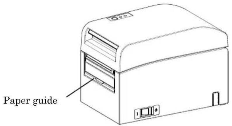
For print length equal to or less than 50 mm: Use the printer with the paper guide closed.
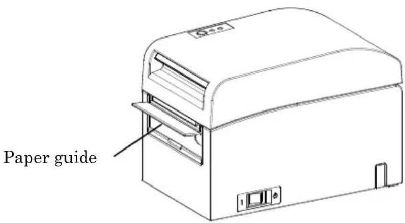
For print length longer than 50 mm: Use the printer with the paper guide open.
5-5. Closing the Top Cover
Place the paper in the correct orientation, and carefully close the top cover.
Note : Place the paper in the correct orientation. If the top cover is closed while the paper is not correctly in place, a paper jam or misaligned printing might occur.
Note : To close the top cover, press it down near its center (the location pointed at in the figure below) until you hear the lock engage. If the cover is not completely locked, printing might be impossible
6. Setting Up the Printer
Introduction to printer setup procedures
You can set the following items for this printer:
(1) Paper type and paper layout
- Die-cut label paper, black mark paper, or plain paper
- Paper width and other paper layout information
(2) Custom paper creation
(3) Sensor adjustment
(4) Print speed
(5) Print density
(6) Printer operation
Item (1), (2) is a required setting.
Items (3) to (6) are optional settings.
The CD-ROM that comes with the printer contains some PDF-formatted online manuals.
For details on how to install and use each of the software programs that come with the printer, see the following documents:
| Document title | Folder | File name |
| Installation Guide \Manuals | LD670_InstallGuide1_en.pdf | |
| Windows Driver User's Guide \Manuals | LD670_WindowsDriverGuide_en.pdf | |
| Utility User's Guide \Manuals | LD670_UtilityGuide_en.pdf | |
| Status Monitor User's Guide \Manuals | LD670_StatusMonitorGuide_en.pdf | |
Detection of paper layout information
The printer supports the following paper types:
a. Plain paper (including full-sheet label paper)
b. Black mark paper
c. Die-cut label paper (including die-cut label paper with black marks)
When using black mark or die-cut paper, the printer can move the paper to the start position, cutting position, peeling-off position, or tear-off position according to the paper layout settings.
To use this function, provide the printer with paper layout information, including the paper type and size, before printing. Use of the printer without these settings may result in a paper layout error or unexpected printouts.
Therefore, set the paper layout when you:
(1) use label paper for the first time,
(2) change the paper type (plain paper, black mark paper, or die-cut label paper),
(3) change the paper size, or
(4) switch to die-cut label paper of the same size as the current paper but with a different base color or other specification.
You can set the paper layout automatically or manually. The next and subsequent pages provide detailed information.
Note: The paper layout must be set under the same temperature conditions as in the actual operating environment of the printer. Otherwise, the cutting position may be outside the base area for labels because of a temperature difference.
Note: - The printer provides a function that automatically detects the paper layout. This automatic layout detection function obtains fixed information on width settings. Therefore, OKI recommends that you manually specify these settings.
Note: - There are two ways to manually set up the printer:
(1) Paper information setting using the driver
(2) Paper information setting using the utility
6-1. Paper Information Setting Using the Driver
Printer setup flow
I. Installing the driver
↓ See "Chapter 3 Installation" in the Installation Guide.
II. Paper layout detection
↓ Provide the printer with the paper layout information described in the Manual Section 6-1-1, "Paper layout."
III. Custom paper creation
↓ Create your custom paper as described in the Manual Section 6-1-2, "Custom paper."
IV. Printing from an application
Perform printing as described in the Manual Section 6-1-3, "Printing from an application." (The use of WordPad is assumed for the procedure described in Section 6-1-3.)
6-1-1. Paper layout
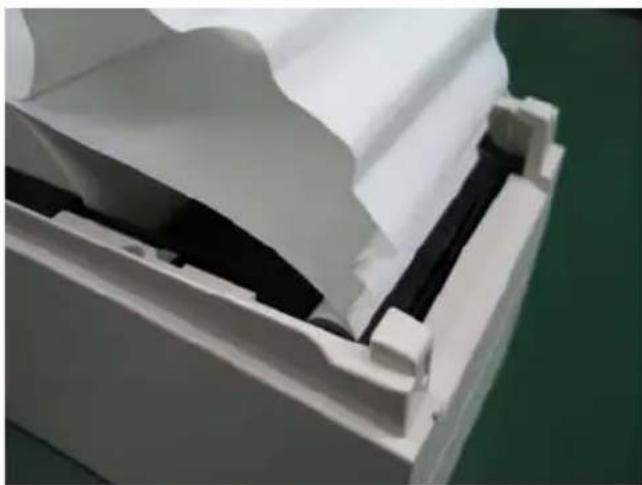
The printer shipped from the factory is configured to enable automatic paper detection. Follow the procedure below to have the printer automatically detect the paper layout information.
natural_image
Hand inserting a white paper into a green printer case (no text or symbols visible)<
(1) Turn on the printer power.
(2) Open the top cover.
(3) Load the paper that you want to use into the printer.
Leave the top cover open.
(4) Press and hold down the FEED switch. The POWER and ERROR lamps blink alternately. Continue to hold down the FEED switch until the POWER and ERROR lamps blink at the same time. At this time, release the FEED switch.
(For details on how to initialize the paper layout, see "How to initialize the paper layout" in Section 7-1, "Control Panel.")
(5) Close the top cover.
(6) The printer feeds the paper, automatically obtains paper layout information, and saves the information.
Note: Automatic layout detection involves a paper feed of several tens of centimeters. This is normal operation.
6-1-2. Custom paper
The printer driver provides a function that allows you to set printer layout information when creating a custom type of paper.
The layout information can be updated even with the printer in paper-layout-error status.
Note: When changing the paper type to plain paper from another type, you must initialize the layout information by following the procedure described in "How to initialize the paper layout" in 7-1 Section, "Control Panel."
Follow the procedure below to register layout information with the printer.
This procedure indicates how to create a custom paper type and send the resulting information to the printer. The use of Windows XP Professional is assumed for the screen shots used in the procedure.
- Click [Start] and then [Printers and Faxes].
* The method of opening the printer folder varies depending on the Windows version.
For details on how to open the printer folder, see "Section 3.1.1 How to Display the Printer Properties" in the Windows Driver User's Guide.
-
Right-click [LD670 Raster], and then select [Properties].
-
Click the [Custom Paper] tab.
(1) Creating a new custom paper type
![LD670 Raster Properties General Sharing Parts Advanced Custom Paper Paper(E): Delete(D) Save(S) Transfer to Printer(E) Create a New Paper(C) Paper Name(N): Label Paper Type(T): Label [5.1] Paper Width: 83.0 - 25.4 - 83.0] mm [5.2] Label Width: 79.0 - 21.4 - 79.0] mm [5.3] Paper Height: 101.5 - 15.0 - 101.5] mm [5.4] Between Labels: 10.0 - 3.0 - 10.0] mm [5.5] Cut Position: 0.0 - 5.0 - 5.0] mm Margin: Left: 3.0 mm Right: 3.0 mm Top: 1.5 mm Bottom: 1.5 mm Unit 0.1mm(M) 0.0inch(J) OK Cancel Apply Help](/content/2026/03/548943/images/56bc015814be8612e0361c4f8139c6fee940bbbc4c936a41894de70cdff62bb2.jpg)
<
(1) Check the [Create a New Paper] check box and enter the paper name.
(2) Select [Paper Type] and enter the appropriate paper information ([S1] to [S5]). Do not change [S5] (cut position) with its default value.
(3) Enter the left, right, top and bottom margins.
(4) Click the [Save] button.
This registers your custom paper settings in the printer driver as paper size information.
(5) Click the [Transfer to Printer] button.
The selected paper layout information is sent to the printer and becomes effective.
(6) Go to step 4.
(2) Using an existing type of paper
![LD670 Raster Properties General Sharing Ports Advanced Custom Paper Page(F) Block Mark Delete(D) Save(S) Create a New Paper(C) Transfer to Printer(P) Paper Name(N): Black Mark Paper Type(O) Block Mark [S1] Paper Width: 50.0 ±[25.4 - 63.0] mm [S2] Label Width: 50.0 ±[25.4 - 63.0] mm [S3] Paper Height: 102.0 ±[15.0 - 300.0] mm [S4] BM Length: 5.0 ±[5.0 - 5.5] mm [S5] Cut Positions: 0.0 ±[0.0 - 102.0] mm Margin: L Left: 3.0 ±mm B Right: 3.0 ±mm U Top: 1.5 ±mm R Bottom: 1.5 ±mm Unit ○ 0.1mm(R) ○ 0.01inch(1) OK Cancel Apply Help](/content/2026/03/548943/images/6b62d2cffc1b97803e0f0dfdc3781d5babe160488899d1d80917ebdf1fc56380.jpg)
<
(1) Select the desired paper that has already been created.
(2) Click the [Transfer to Printer] button.
The selected paper layout information is sent to the printer and becomes effective.
(3) Go to step 4.
4 When a confirmation message appears, respond as instructed and then click the [OK] button.
* You may encounter a paper layout error when attempting to replace paper in one of the following patterns:
- Change from die-cut label paper to plain paper
- Change from black mark paper to plain paper
- Change from die-cut label paper to black mark paper
- Change to paper having a different paper layout
* If the error remains even after setting is completed, re-verify that the paper loaded on the printer matches the custom paper setting.
* The [Transfer to Printer] button works even when the new paper is not loaded. Before actually printing data, however, be sure to replace the paper.
* If the newly set type of paper is not plain paper, the printer feeds paper up to the top-of-form position.
5 In the LD670 Raster Properties window, click the [OK] button.
6-1-3. Printing from an application
You can print a document from an application using paper information registered in the printer driver.
The procedure below explains how to print a document to the LD670 printer using WordPad as an example.
- From the WordPad [File] menu, select [Page Setup].
- The Page Setup window appears. Click the [Print Setup] button.
-
In the [Printer Name] field, specify [LD670 Raster] as the target printer.
-
Click the [Properties] button to configure printing preferences for the printer driver.
* The button used to open the printing preferences window varies from one application to another. For example, the [Options] button is used for this purpose in Excel.
* Some applications (including Word) also assume use of the Print window for setting printing preferences, instead of providing a separate Page Setup window.
For details on the Print window, see the description in step 10 later.
- The LD670 Raster Properties (printing preferences) window appears. Specify desired printing preferences, and then click the [OK] button.
- Click the [OK] button in the Page Setup window to close the window.
- In Page Setup window, specify the paper size, orientation and margins, and then click the [OK] button.
- Edit a document in the WordPad edit window.
-
Select [Print] from the [File] menu.
-
The [Print] window appears.
Click the [Advanced] button to specify printing preferences for the printer driver.
-
Specify [Page Range] and [Copies] when necessary, and then click the [Print] button.
-
Print data is sent to the printer and printing starts.
6-2. Paper information setting using the utility
6-2-1. Paper layout
The printer shipped from the factory is configured to enable automatic paper detection. Follow the procedure below to have the printer automatically detect the paper layout information.
natural_image
Hand inserting a white paper into a green electronic device (no visible text or symbols)<
(1) Turn on the printer power.
(2) Open the top cover.
(3) Load the paper that you want to use into the printer.
Leave the top cover open.
(4) Press and hold down the FEED switch. The POWER and ERROR lamps blink alternately. Continue to hold down the FEED switch until the POWER and ERROR lamps blink at the same time. At this time, release the FEED switch.
(For details on how to initialize the paper layout, see "How to initialize the paper layout" in Section 7-1, "Control Panel.")
(5) Close the top cover.
(6) The printer feeds the paper, automatically obtains paper layout information, and saves the information.
Note: Automatic layout detection involves a paper feed of several tens of centimeters. This is normal operation.
6-2-2. Setting detailed paper layout information
The printer utility provides a function that allows you to set printer layout information.
The layout information can be updated even with the printer in paper-layout-error status.
Follow the procedure below to register layout information with the printer.
This procedure explains how to send layout information to the printer.
The use of Windows XP Professional is assumed for the screen shots.
- Click [Start], [All Programs], [Okidata], and [LD670 Utility] in this order.
* The method of running the printer utility varies depending on the Windows version. See "Section 3.1 Starting LBL32" in the Utility User's Guide.
-
Select [LD670 Raster] and then click [OK].
-
Click the [Paper Layout] tab.
![LBL32 File(F) Send(S) Help(H) Paper Layout Memory Switch Customize Value Others [S1]Paper Width 70.0 25.4-70.0,80.0,83.0mm Set Layout □ Automatically set the paper layout Paper Detection Auto Layout manual setting Paper Type Label [S3]Label Width 79.0 [21.4-86.0]mm [S3]Paper Height 101.6 [15.0-101.6]mm [S4]Between Labels 10.0 [3.0-10.0]mm [S5]Cut Position 0.0 [-5.0-5.0]mm Margin 3.0 mm [T]Top Margin 1.5 mm [L]Left Margin 3.0 mm [B]Bottom Margin 1.5 mm [R]Right Margin Base Adjustment: 0.0 mm Unit TearOff Adjustment: 0.0 mm Set Base/TearOff 0.1mm Operation Guide Setting(S) List Printing(E) Exit(X)](/content/2026/03/548943/images/a188ed5771d5dc206b6276ea7709b91366fa198e991e2046375fbbb04e1ffb84.jpg)
<>
(1) Uncheck the [Automatically set the paper layout] check box.
(2) Select [Paper Type] and enter the appropriate paper information ([S1] to [S5]). Do not change [S5] (cut position) with its default value.
(3) Enter the left, right, top and bottom margins as required.
(4) Click the [Set Layout] button.
The paper layout information you entered in this window is sent to the printer and becomes effective.
4 When a confirmation message appears, respond as instructed and then click the [OK] button.
5 A message appears, prompting you to replace the paper with paper targeted by the layout setting. Replace the paper and click the [OK] button.
* If the error remains even after setting is completed, re-verify that the paper loaded on the printer matches the paper setting.
* If the newly set type of paper is not plain paper, the printer feeds paper up to the top-of-form position.
6-3. Setting Paper Information Using the Printer
6-3-1. Automatic layout detection
The printer shipped from the factory is configured to enable automatic paper detection. Follow the procedure below to have the printer automatically detect the paper layout information.
<>
(1) Turn off the printer power.
(2) Open the top cover.
(3) Turn on the printer power.
(4) Load the paper that you want to use into the printer. Leave the top cover open.
(5) Press and hold down the FEED switch. The POWER and ERROR lamps blink alternately. Continue to hold down the FEED switch until the POWER and ERROR lamps blink at the same time. At this time, release the FEED switch. (For details on how to initialize the paper layout, see "How to initialize the paper layout" in Section 7-1, "Control Panel.")
(6) Close the top cover.
(7) The printer feeds the paper, automatically obtains paper layout information, and saves the information.
Note: Automatic layout detection involves a paper feed of several tens of centimeters. This is normal operation.
Note: The printer's automatic layout detection function cannot obtain the paper width setting as part of paper information. For details on how to set the paper width, see Example 7) in Section 10-2, "Setting Up the Printer."
Note: If you need to specify information other than the paper width, follow the procedure described in Section 6-1, "Paper Information Setting Using the Driver," or 6-2, "Paper Information Setting Using the Utility."
6-3-2. Setting the Paper Width
The printer utility provides a function that allows you to set a paper width on the printer.
The paper width can be set even with the printer in paper-layout-error status.
Follow the procedure below to set a paper width on the printer.
This procedure explains how to send your paper width setting to the printer. The use of Windows XP Professional is assumed for the screen shots.
- Click [Start], [All Programs], [Okidata], and [LD670 Utility] in this order.
* The method of opening the printer folder varies depending on the Windows version.
For details on how to open the printer folder, see "Section 3.1, Starting LBL32" in the Utility User's Guide.
-
Select [LD670 Raster] and then click [OK].
-
Click the [Paper Layout] tab.
![LBL32 File(E) Send(S) Help(H) Paper Layout Memory Switch Customize Value Others [S1]Paper Width 70.0 [25.4-70.0,80.0,83.0]mm Layout Auto Set ✓ Automatically set the paper layout Paper Detection Auto Layout manual setting Paper Type Name [S2]Label Width 70.0 [25.4-63.0]mm [S3]Paper Height 297.0 [15.0-2039.9]mm [S4]Between Labels 0.0 [0.0-0.0]mm [S5]Cut Position 0.0 mm Margin [L]Left Margin 3.0 mm [T]Top Margin 0.0 mm [R]Right Margin 3.0 mm [B]Bottom Margin 0.0 mm Base Adjustment: 0.0 mm TextOff Adjustment: 0.0 mm Set Base/TearOff Unt ○ 0.1mm ○ 0.01inch Operation Guide Setting(O) List Printing(E) Exit(X)](/content/2026/03/548943/images/ddf24b021e95791e20bee3197cbba8a14a189c7a91240ab193116403e1748020.jpg)
<
(1) Enter the paper width.
(2) Click the [Layout Auto Set] button.
4 When a confirmation message appears, respond as instructed and then click the [OK] button.
5 A message appears, prompting you to replace the paper with paper targeted by the layout setting. Replace the paper and click the [OK] button.
Note: Automatic paper size setting involves a paper feed of several tens of centimeters for layout detection. This is normal operation.
6-3-3. Automatic layout detection
The automatic layout settings are configured as follows:
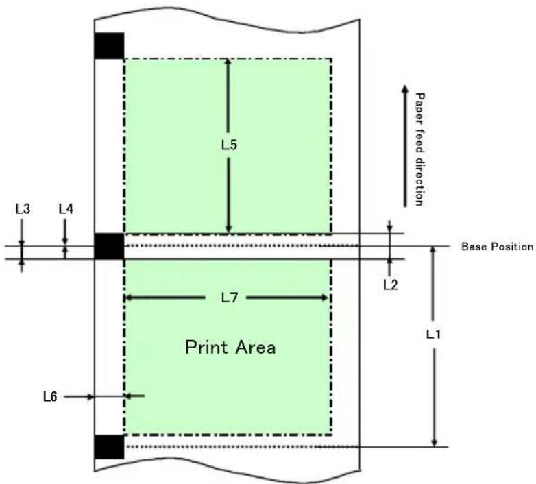
Black mark paper
L1: Length from the vertical reference position to the next reference
Position
: Automatically detected
L2: Length of the detection area for the vertical reference position
: 5.0mm to 5.5mm
L3: Length from the vertical reference position to the start position
: 1.5mm
L4: Length from the vertical reference position to the cutting position
: 0.0mm
L5: Print area length : (L1 - 1.5 x 2) mm
L6: Length from the left edge of the paper to the left end of the print area
: 11.0 mm (for a paper width of 83 mm)
: 4.0 mm (for a paper width of 80 mn
: 3.0 mm (for other paper widths)
L7: Print area width : 80.0 mm (for a paper width of 83 mm)
(Paper width - L6 x 2) mm (for other paper widths)
Note: L1 to L7 above are values detected by the printer sensor.
These values do not match the S1 to S5, L, R, T, and B parameter values specified by the driver or utility.
Note: If the paper length (L1) of the loaded roll paper differs by ±10% or more from the initially set paper length (L1) or that set upon automatic recognition, an error occurs because the type of loaded roll paper is considered illegal.
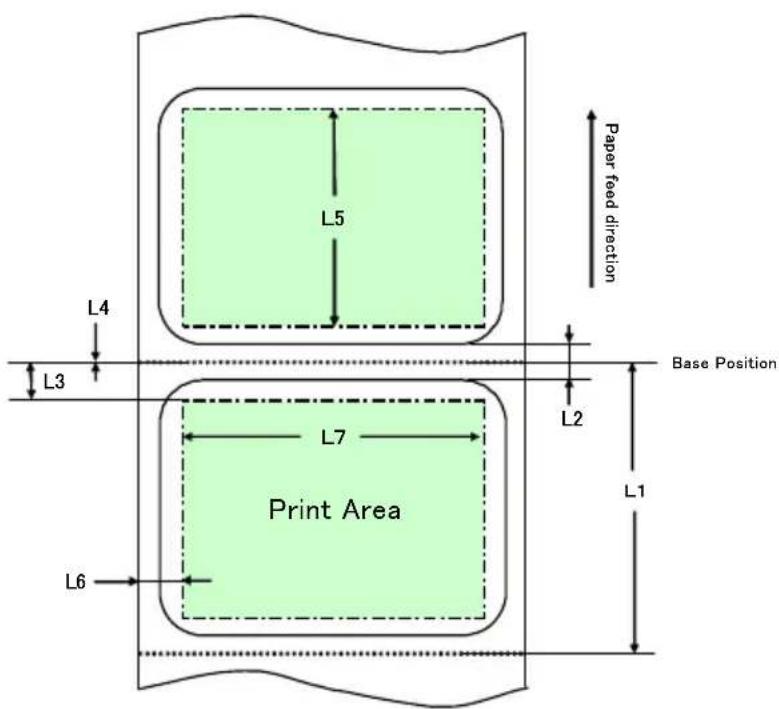
Die-cut label paper
L1: Length from the vertical reference position to the next reference position
: Automatically detected
L2: Length of the detection area for the vertical reference position
: Automatically detected
L3: Length from the vertical reference position to the start position
: (L2/2 + 1.5) mm
L4: Length from the vertical reference position to the cutting position
: 0.0 mm
L5: Print area length : (L1 - L3 x 2) mm
L6: Length from the left edge of the paper to the left end of the print area
: 5.0 mm
L7: Print area width : (Paper width setting - L6 x
Note: L1 to L7 above are values detected by the printer sensor.
These values do not match the S1 to S5, L, R, T, and B parameter values specified by the driver or utility.
Note: If the paper length (L1) of the loaded roll paper differs by ±10% or more from the initially set paper length (L1) or that set upon automatic recognition, an error occurs because the type of loaded roll paper is considered illegal.
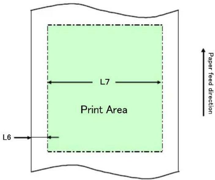
Plain paper (including full-sheet label paper)
L1: Length from the vertical reference position to the next reference position
: Not determined
L2: Length of the detection area for the vertical reference position
: Not determined
L3: Length from the vertical reference position to the start position
: Not determined
L4: Length from the vertical reference position to the cutting position
: Not determined
L5: Print area length : Not determined
L6: Length from the left edge of the paper to the left end of the print area
: 1.0 mm (for a paper width of 83 mm)
: 4.0 mm (for a paper width of 80 mm)
: 3.0 mm (for other paper widths)
L7: Print area width
: 80.0 mm (for a paper width of 83 mm)
(Paper width - L6 x 2) mm (for other paper widths)
Note: L1 to L7 above are values detected by the printer sensor.
These values do not match the S1 to S5, L, R, T, and B parameter values specified by the driver or utility.
6-4. Replacing paper
The paper replacement procedure is as follows.
Automatic layout detection
<
(1) Turn off the printer power, and open the top cover.
(2) Turn on the printer power.
(3) Load the paper that you want to use into the printer. Leave the top cover open.
(4) Press and hold down the FEED switch. The POWER and ERROR lamps blink alternately. Continue to hold down the FEED switch until the POWER and ERROR lamps blink at the same time. At this time, release the FEED switch.
(5) Close the top cover.
(6) The printer feeds the paper, automatically obtains paper information, and saves the information.
Note: Automatic layout detection involves a paper feed of several tens of centimeters. This is normal operation.
Updating the layout information
Re-specify paper information by following the procedure described in Section 6-1-2, "Custom paper," or 6-2-2, "Setting detailed paper layout information."
6-5. Paper Layout Errors
When using black mark or die-cut label paper, the printer monitors the paper length (L1) based on the set paper layout. If the detected paper length does not match the set paper length, a paper layout error occurs.
(1) Error when paper is being loaded
Confirm that the paper being loaded is the same as the paper specified in the paper layout information for the printer. If not, replace the paper with paper that matches the paper layout information.
(2) Error during printing
If a paper layout error occurs during printing, open the top cover, check whether label peeling, a paper jam or other problem has occurred, reposition the paper, and then close the top cover.
(3) Error when paper is being replaced
Follow the procedure in "Section 6-4. Replacing paper."
Note: If the paper length (L1) of the loaded paper is ±10% different from your specified paper length or that set through automatic detection, a paper layout error occurs.
6-6. Adjusting Sensors
1) There are two ways to adjust sensors:
a. Automatic sensor adjustment (This mode is set at the time of shipment from the factory.)
b. Manual sensor adjustment
■ Automatic sensor adjustment
1) With this mode enabled, the sensor is automatically adjusted in parallel with automatic layout detection. This adjustment sets optimal values based on the measured sensor input level.
Sensor adjustment values are not preset at shipping. However, when you load paper on the printer and initially power on the printer, the automatic layout detection function will set the sensor adjustment values.
■ Manual sensor adjustment
1) You can start manual adjustment of a sensor by selecting the sensor in sensor adjustment mode, which is a special mode. The printer prints instructions for operations. Adjust the sensor by following these instructions.
2) Automatic sensor adjustment is enabled at the time of shipment from the factory. The printer as shipped need not be manually adjusted because sensors are automatically adjusted at the same time as automatic layout detection. Adjust sensors manually only if a paper layout error frequently occurs.
6-7. Print Density Setting
The printer can specify a print density for the paper to be used.
The print density is preset to 130% at shipping. You can change this setting to the value appropriate for the paper to be used as described in Section 3-5, "Recommended Thermal Paper."
There are three methods of changing the setting:
(1) Using the Windows printer driver See "Section 4.4 [Graphics] Tab" in the Windows Driver User's Guide.
(2) Using the printer utility See "Section 3.2.5 Customize Value" in the Utility User's Guide.
(3) Setting up the printer Change the setting as described in Example (1) in Section 10-2, "Setting Up the Printer."
* If you have specified a print density using the Windows driver, the print density specified by the driver will be used for printing. (The print density specified by the driver takes precedence over print density specified by the utility.)
6-8. Print Speed Setting
There are three methods of changing the setting:
(1) Using the Windows printer driver See "Section 4.4 [Graphics] Tab" in the Windows Driver User's Guide.
(2) Using the printer utility See "Section 3.2.5 Customize Value" in the Utility User's Guide.
(3) Setting up the printer Change the settings as described in Example (2) in Section 10-2, "Setting Up the Printer."
* If you have specified a print speed using the Windows driver, the print speed specified by the driver will be used for printing. (The print speed specified by the driver takes precedence over print speed specified by the utility.)
Note: The printer restricts the print speed when using paper with a width of 57 mm or less.
Up to 260 mm/s for a paper width within a range of 83 to 58 mm Up to 180 mm/s for a paper width within a range of 57 to 38 mm Up to 80 mm/s for a paper width within a range of 37 to 25.4 mm
6-9. Cutting Position Correction
This printer allows you to correct (upward or downward) the top-of-form position, cut position, peeling-off position and tear-off position. Change the setting as required.
You can use one of the following methods to change this setting.
(1) Using the Windows printer driver
See "Section 4.1 [Custom Paper] Tab" in the Windows Driver User's Guide.
(2) Using the printer utility
See "Section 4.3 Adjusting Cut Position or Tear Off Position" in the Utility User's Guide.
6-10. Other Settings
This printer allows you to specify whether to feed paper up to the top-of-form position at power-on and whether to cut paper upon the closing of the cover.
There are two methods of changing the setting:
(1) Setting up the printer Change the setting as described in Example (4) in Section 10-2, "Setting Up the Printer."
(2) Using the printer utility See "Section 3.2.4 Memory Switch settings" in the Utility User's Guide.
6-11. Initializing the Printer Setup Information
You can disable the settings you specified on the printer and restore the default settings preset at shipping.
Initialize the settings as described in Example 5) in Section 10-2, "Setting Up the Printer."
7. Control Panel
7-1. Control Panel
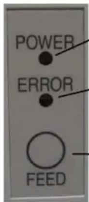
POWER lamp (●)
Lights when the power switch is turned on and power is supplied to the printer.
ERROR lamp (●)
Lights or blinks to indicate errors.
FEED switch
- Plain paper (including full-sheet label paper)
Pressing this switch once advances the paper one line. Holding down this switch advances paper continuously. - Paper type other than plain paper (including full-sheet label paper) Pressing this switch once feeds one sheet of paper.
* How to initialize the paper layout
Pressing the FEED switch with the top cover open initializes the paper layout information. After initialization is completed, load the paper you want to use and then close the top cover. The printer feeds paper, automatically retrieves paper information, and retains the paper layout information.
(1) Initialization
- Initialization initializes the paper layout information. You can use initialization when changing the layout information while using the same type of paper.
- Procedure: Press and hold down the FEED switch for a while. The POWER and ERROR lamps will start blinking alternately. At this time, release the FEED switch.
(2) Full initialization
- Full initialization initializes the paper type setting in addition to paper layout information. Use it when you change the type of paper.
- Procedure: Press and hold down the FEED switch for a while. The POWER and ERROR lamps will start blinking alternately. When you continue holding down the FEED switch, the POWER and ERROR lamps will blink simultaneously. At this time, release the FEED switch.
7-2. Error Indications
Recoverable errors
| Error condition | LED LAMP | Blinking pattern |
| No paper (paper end) | POWER (●) | Constantly on |
| ERROR (●) | Constantly on | |
| Cover open | POWER (●) | Constantly on |
| ERROR (●) | Constantly on | |
| Head hot (*1) | POWER (●) | Constantly on |
| ERROR (●) | Constantly on |
*1 Printing is suspended because of a high thermal head temperature.
| Error condition | LED LAMP | Blinking pattern |
| Paper near end | POWER (●) | Constantly on |
| ERROR (●) | ||
| Paper layout error | POWER (●) | Constantly on |
| ERROR (●) | ||
| Repeated blinking of the amber lamp four times in succession |
Unrecoverable errors
| Error condition | LED LAMP Blinking pattern | |
| Internal error | POWER (●) | —●—●— |
| ERROR (●) | ●— | |
| Repeated pattern in which the green lamp blinks twice and the amber lamp blinks once | ||
| Head not installed | POWER (●) | —●—●—●— |
| ERROR (●) | ●— | |
| Repeated pattern in which the green lamp blinks three times and the amber lamp blinks once | ||
| Low voltage | POWER (●) | —●—●—●—●— |
| ERROR (●) | ●— | |
| Repeated pattern in which the green lamp blinks four times and the amber lamp blinks once | ||
| Over voltage | POWER (●) | —●—●—●—●—●— |
| ERROR (●) | ●— | |
| Repeated pattern in which the green lamp blinks five times and the amber lamp blinks once | ||
| Cutter functioning abnormally | POWER (●) | —●—●—●—●—●—●— |
| ERROR (●) | ●— | |
| Repeated pattern in which the green lamp blinks six times and the amber lamp blinks once | ||
| LF motor functioning abnormally | POWER (●) | —●—●—●—●—●—●—●— |
| ERROR (●) | ●— | |
| Repeated pattern in which the green lamp blinks seven times and the amber lamp blinks once | ||
8. Preventing and Clearing Paper Jams
8-1. Preventing Paper Jams
Do not touch the paper while the paper is being ejected or cut. Holding or pulling the paper by hand during ejection might cause a paper jam, incorrect cutting, or a feed error.
8-2. Clearing a Paper Jam
If a paper jam occurs, remove the jammed paper as follows:
(1) Turn off the printer power by turning off the power switch.
(2) Press the cover open lever down, and open the top cover.
(3) Pull out the jammed paper slowly toward the top while holding down the printer, as shown in the picture below.
natural_image
Close-up of a white plastic panel with black insulation and black cladding, no visible text or symbols
natural_image
Close-up of hands installing or adjusting a device into a white plastic container (no visible text or symbols)Note: Do not pull the paper with excessive force. Note: Do not touch the thermal head. Doing so may result in damage from static electricity.
9. Troubleshooting
This chapter describes the appropriate action to be taken in cases where the printer is not operating correctly or fails to produce clean printouts.
9-1. Power-on Problems and Errors
| Symptom | Cause | Corrective |
| Although the power has been turned on, the POWER lamp on the control panel does not light and the printer does not start up. | (1) The power cable is disconnected.(2) The connector of the AC adapter is disconnected. | (1) Connect the power cable.(2) Connect the connector of the AC adapter. |
| The ERROR lamp on the control panel is lit, and the printer does not work. | (1) No paper is inserted.(2) The top cover is not closed completely.(3) The thermal head is at a high temperature. | (1) Insert paper.(2) Close the top cover completely.(3) Wait until the thermal head temperature decreases sufficiently. |
9-2. Cutter-related Problems
| Symptom | Cause | Corrective |
| Paper cannot be cut. (1) | The cutter blade is damaged or worn, or it has been used for too long.(2) Paper fragments or other foreign matter is stuck around the cutter blade or paper chute.(3) Adhesive matter is adhering to the cutter blade because of printing on label paper. | (1) Turn off the power, and ask for repairs.(2) Remove the paper fragments or foreign matter.(3) Clean the cutter blade to remove the adhesive matter. |
| The cutter does not return to the correct position. | Paper fragments or other foreign matter is stuck around the cutter blade or paper chute. | Remove the paper fragments or foreign matter. |
9-3. Printing-related Problems
| Symptom | Causes | Corrective action |
| Printing does not begin. | (1) The interface cable is disconnected or broken.(2) The printer setup is incorrect. | (1) Connect the interface cable correctly, or replace it.(2) Set up the printer correctly. Example: An incorrect baud rate is set.(See "10-2 Setting Up the Printer.") |
| The printing is too dark or blurry. | (1) The print density setting included in the printer setup is incorrect.(2) The thermal head is damaged. | (1) Adjust the print density and print speed settings of the printer so that they are appropriate to the paper.(See "10-2 Setting Up the Printer.")(2) Turn off the power, and ask for repairs. |
| Printed characters are thin (faint). | (1) The print density setting included in the printer setup is incorrect.(2) The thermal head is damaged. | (1) Adjust the print density and print speed settings of the printer so that they are appropriate to the paper.(See "10-2 Setting Up the Printer.")(2) Turn off the power, and ask for repairs. |
| The print density is uneven. | (1) Paper fragments or foreign matter is stuck on the heating elements of the thermal head.(2) The printer setup is incorrect.(3) Foreign matter is adhering to the platen roller.(4) The thermal head is damaged. | (1) Check and clean the thermal head.(2) Adjust the print density and print speed settings of the printer so that they are appropriate to the paper. Set up the printer correctly.(See "10-2 Setting Up the Printer.")(3) Remove the foreign matter from the platen roller.(4) Turn off the power, and ask for repairs. |
| Vertical marks appear on the printout. | (1) Foreign matter is stuck or caught on the paper transport.(2) Foreign matter is adhering to the thermal head(3) The thermal head is damaged. | (1) Clean the paper transport.(2) Clean the thermal head.(3) Turn off the power, and ask for repairs. |
10. Special Modes
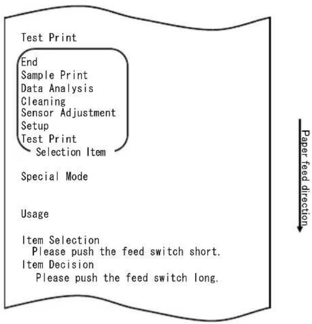
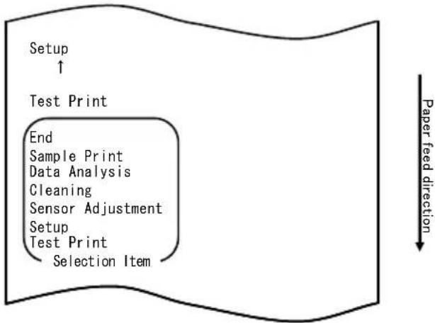
10-1. Test Printing
With paper inserted in the printer, turn off the printer power switch once, and turn on the switch again while holding down the FEED switch on the control panel. Then, the data shown below is printed. When "TEST PRINT" is printed, press and hold down the FEED switch for one second or longer to start test printing.
After printing a certain amount of data, the printer automatically cuts the paper and ends the test printing. To terminate test printing in progress, press the FEED switch. Then, the printer cuts the paper and terminates the test printing.
Note: You must hold down the FEED switch until the printer starts printing.
Note: If you have passed the item that you want to select, quickly press the FEED switch repeatedly until you return to the first item.
Test printing
flowchart
graph TD
    A["Test Print"] --> B["End"]
    B --> C["Sample Print"]
    C --> D["Data Analysis"]
    D --> E["Cleaning"]
    E --> F["Sensor Adjustment"]
    F --> G["Setup"]
    G --> H["Test Print"]
    H --> I["Selection Item"]
    J["Special Mode"] --> K["Usage"]
    L["Item Selection"] --> M["Please push the feed switch short."]
    N["Item Decision"] --> O["Please push the feed switch long."]
    P["Paper feed direction"] --> Q
The printer stops after printing the selection items.
- When you press the FEED switch briefly (one second or less), the printer ends test printing.
- When you press and hold down the FEED switch for one second or longer, the printer continues test printing to print a list of fonts. To terminate printing of the font list in progress, press the FEED switch. The printer cuts the paper and terminates printing of the font list.
Sample test printout
10-2. Setting Up the Printer
This section explains how to set up the printer without using a PC.
With the printer connected to a Windows PC, you can easily change the settings by using the utility software contained on the CD-ROM provided with the printer.
For details on how to install and run the utility, see "Chapter 3 Installation" in the Installation Guide.
For details on the functions of the utility and how to use it, see the Utility User's Guide.
This section describes the typical setting changes listed below in detail.
Example (1) Changing the print density to a lower value
Example (2) Changing the print speed to a higher value
Example (3) Changing to use two-color thermal paper
Example (4) Changing the top-of-form position at power-on
Example (5) Initializing the printer settings
Example (6) Disabling paper-near-end detection
Example (7) Changing the paper width
Example (8) Switching to batch printing
Example (1): Changing the Print Density
Change from 130% to 100%
The procedure for this setting is as follows.
- Before starting work for this setting, verify the following conditions of the printer:
(1) The power is off.
(2) Roll paper is inserted in it.
(3) The cover is closed.
- Enter special mode.
Turn on the power switch on the right side of the printer while holding down the FEED switch on the left part of the Top cover.
Note: You must hold down the FEED switch until the printer starts printing.
Note: If you have passed the item that you want to select, quickly press the FEED switch repeatedly until you return to the first item.
The printer prints the following when it enters special mode:

flowchart
graph TD
    A["Test Print"] --> B["End"]
    B --> C["Sample Print"]
    C --> D["Data Analysis"]
    D --> E["Cleaning"]
    E --> F["Sensor Adjustment"]
    F --> G["Setup"]
    G --> H["Test Print"]
    H --> I["Selection Item"]
    J["Special Mode"] --> K["Usage"]
    L["Item Selection"] --> M["Please push the feed switch short."]
    N["Item Decision"] --> O["Please push the feed switch long."]
    P["Paper feed direction"] --> Q
- Enter setup mode from special mode.
Press the FEED switch briefly (one second or less) once to move to "SETUP".
flowchart
graph TD
    A["Setup ↑"] --> B["Test Print"]
    B --> C["End\nSample Print\nData Analysis\nCleaning\nSensor Adjustment\nSetup\nTest Print\nSelection Item"]
    C --> D["Paper feed direction ↓"]
Then, press and hold down the FEED switch for one second or longer to accept the selection.
The printer prints the following when it enters setup mode:
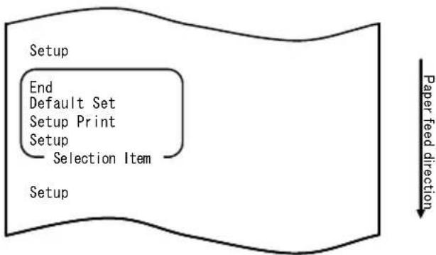
flowchart
graph TD
    A["Setup"] --> B["End"]
    B --> C["Default Set"]
    C --> D["Setup Print"]
    D --> E["Setup"]
    E --> F["Selection Item"]
    F --> G["Setup"]
    style A fill:#f9f,stroke:#333
    style G fill:#ccf,stroke:#333
    note right of G Paper feed direction
- In setup mode, select "SETUP"
Press and hold down the FEED switch for one second or longer to accept the selection.
The printer prints the following when you accept the selection of "SETUP":
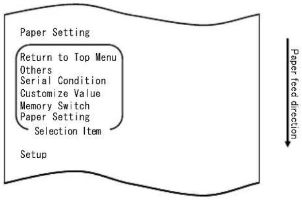
flowchart
graph TD
    A["Paper Setting"] --> B["Return to Top Menu"]
    B --> C["Others"]
    C --> D["Serial Condition"]
    D --> E["Customize Value"]
    E --> F["Memory Switch"]
    F --> G["Paper Setting"]
    G --> H["Selection Item"]
    H --> I["Setup"]
    style A fill:#f9f,stroke:#333
    style I fill:#ccf,stroke:#333
- Select "CUSTOMIZE VALUE" as your option.
Quickly press the FEED switch twice (up to one second each) to move to "CUSTOMIZE VALUE".
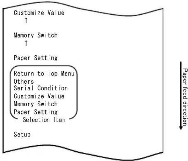
flowchart
graph TD
    A["Customize Value ↑"] --> B["Memory Switch ↑"]
    B --> C["Paper Setting"]
    C --> D["Return to Top Menu"]
    D --> E["Others"]
    D --> F["Serial Condition"]
    D --> G["Customize Value"]
    D --> H["Memory Switch"]
    D --> I["Paper Setting"]
    I --> J["Selection Item"]
    J --> K["Setup"]
    L["Paper feed direction"] --> M
Then press and hold down the FEED switch for at least one second to accept the selection.
The printer prints the following upon your acceptance of "CUSTOMIZE VALUE" selection:
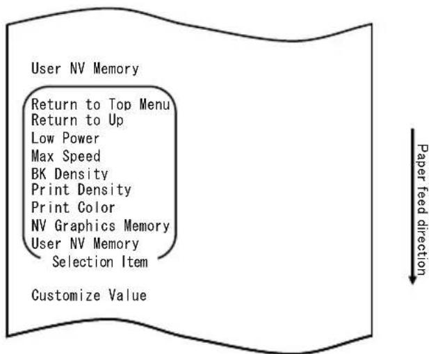
- Select "PRINT DENSITY" as your option.
Press the FEED switch briefly (one second or less) three times to move to "PRINT DENSITY".
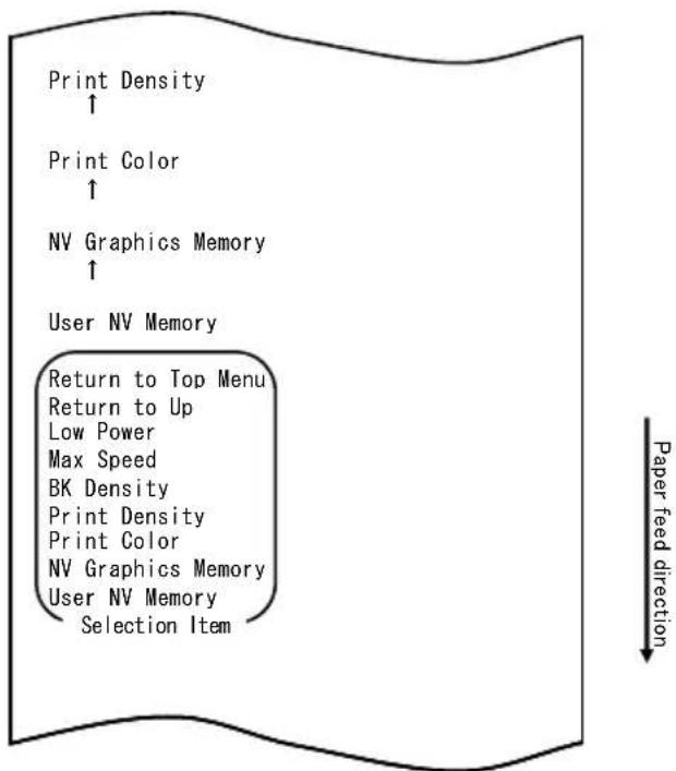
flowchart
graph TD
    A["Print Density ↑"] --> B["Print Color ↑"]
    B --> C["NV Graphics Memory ↑"]
    C --> D["User NV Memory"]
    D --> E["Return to Top Menu"]
    E --> F["Return to Up"]
    F --> G["Low Power"]
    G --> H["Max Speed"]
    H --> I["BK Density"]
    I --> J["Print Density"]
    J --> K["Print Color"]
    K --> L["NV Graphics Memory"]
    L --> M["User NV Memory"]
    M --> N["Selection Item"]
Then, press and hold down the FEED switch for one second or longer to accept the selection.
The printer prints the following when you accept the selection of "PRINT DENSITY":
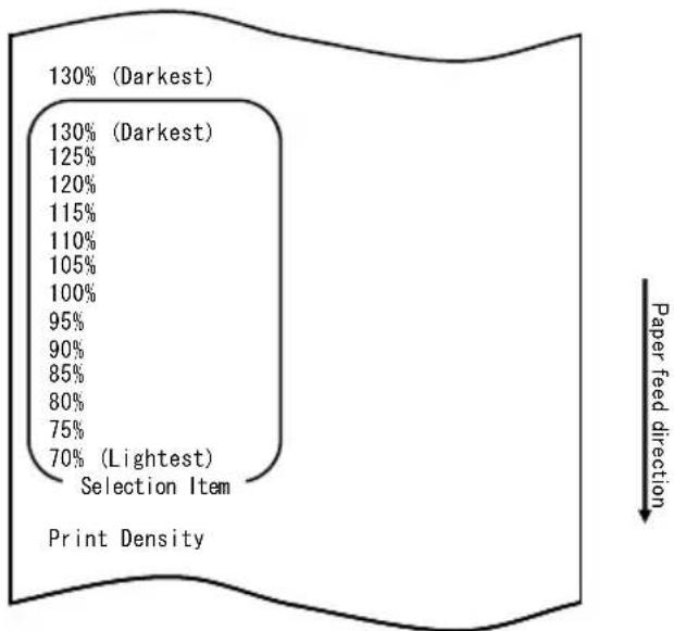
pie
| Category | Percentage (%) | | :--- | :--- | | Darkest | 130 | | Darkest | 130 | | Darkest | 125 | | Darkest | 120 | | Darkest | 115 | | Darkest | 110 | | Darkest | 105 | | Darkest | 100 | | Darkest | 95 | | Darkest | 90 | | Darkest | 85 | | Darkest | 80 | | Darkest | 75 | | Darkest | 70 | | Lightest | (Selection Item) | | Paper feed direction (Top) | (Bottom) | | Print Density (Bottom) | (Bottom) |- Select "100%" as your option.
Press the FEED switch briefly (one second or less) until the item "100%" is reached.
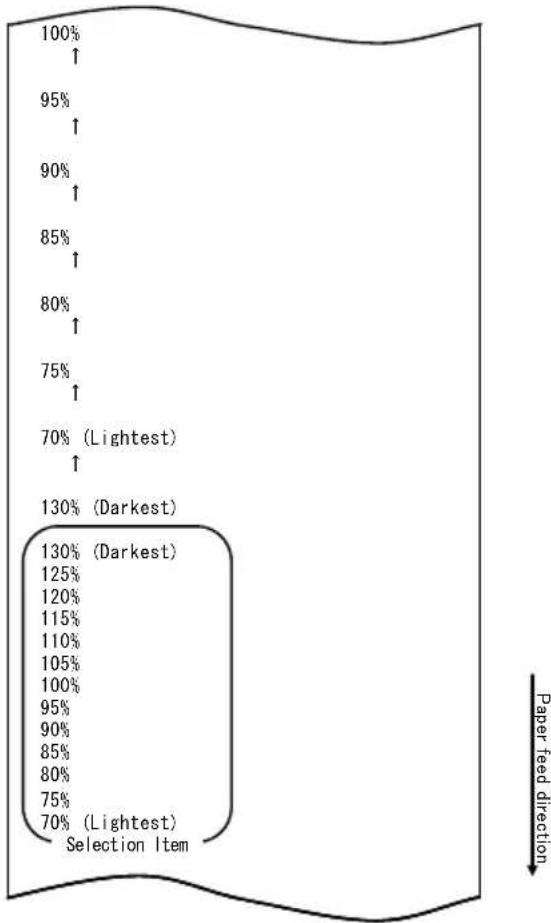
other
| Paper feed direction | Percentage (%) | | :--- | :--- | | Lightest | 70 | | Darkest | 130 | | Lightest | 100 | | Darkest | 95 | | Darkest | 90 | | Darkest | 85 | | Darkest | 80 | | Darkest | 75 | | Darkest | 80 | | Darkest | 95 | | Darkest | 120 | | Darkest | 125 | | Darkest | 130 |Then, press and hold down the FEED switch for one second or longer to accept the selection.
The printer prints the following when you accept the selection of "100%":
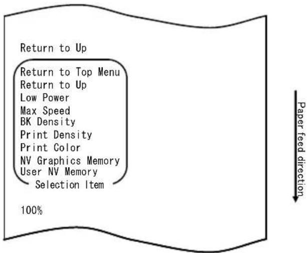
- Select "RETURN TO UP" as your option.
Press and hold down the FEED switch for one second or longer to accept the selection.
The printer prints the following when you accept the selection of "RETURN TO UP":
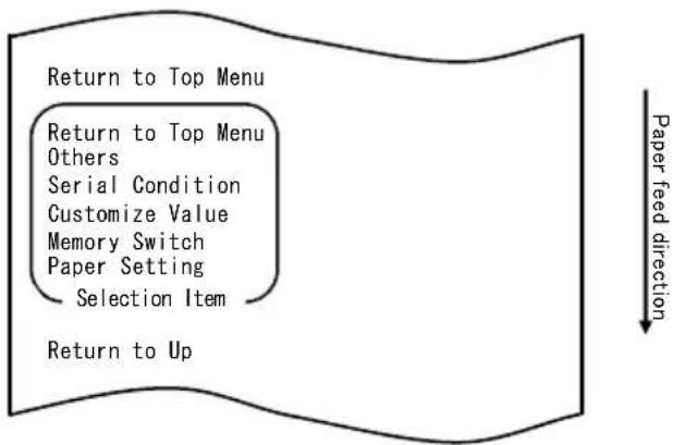
flowchart
graph TD
    A["Return to Top Menu"] --> B["Return to Top Menu\nOthers"]
    B --> C["Serial Condition"]
    C --> D["Customize Value"]
    D --> E["Memory Switch"]
    E --> F["Paper Setting"]
    F --> G["Selection Item"]
    G --> H["Return to Up"]
- Select "RETURN TO TOP MENU" as your option.
The printer prints the following when you accept the selection of "RETURN TO TOP MENU":
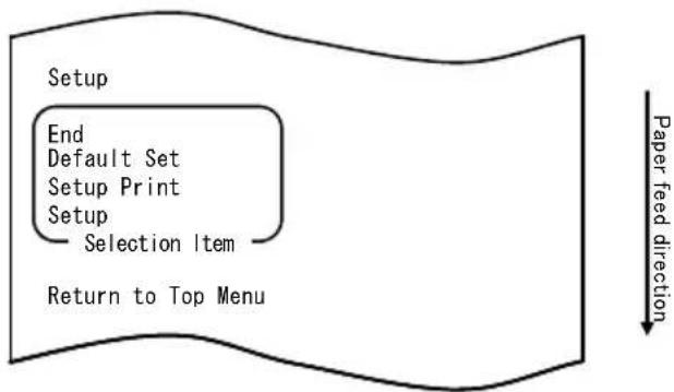
flowchart
graph TD
    A["Setup"] --> B["End"]
    B --> C["Default Set"]
    C --> D["Setup Print"]
    D --> E["Setup"]
    E --> F["Selection Item"]
    F --> G["Return to Top Menu"]
    H["Paper feed direction"] --> I["Next Step"]
- Select "END" as your option.
Quickly press the FEED switch three times (up to one second each) to move to "END".
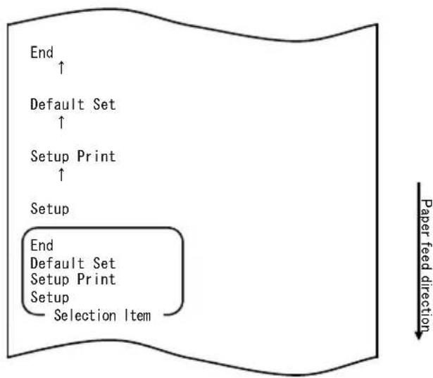
flowchart
graph TD
    A["End"] --> B["Default Set"]
    B --> C["Setup Print"]
    C --> D["Setup"]
    D --> E["End"]
    E --> F["Default Set"]
    F --> G["Setup Print"]
    G --> H["Setup"]
    H --> I["Selection Item"]
    style E fill:#f9f,stroke:#333
    style F fill:#f9f,stroke:#333
    style G fill:#f9f,stroke:#333
    style H fill:#f9f,stroke:#333
    style I fill:#f9f,stroke:#333
Then, press and hold down the FEED switch for one second or longer to accept the selection.
The printer cuts the paper and exits from setup mode when you accept the selection of "END".
Note: If you turn off the printer power switch without first selecting "END", your setting will be lost.
- Verifying your setting
To verify your setting, execute a test print, referring to Section 10-1. The test printing prints a list of printer settings. Check the list, and verify your setting.
Example (2): Changing the Max Speed
Change from 5 (Max. 140 mm/s) to 9 (Max. 260 mm/s)
The procedure for this setting is as follows.
- Before starting work for this setting, verify the following conditions of the printer:
(1) The power is off.
(2) Roll paper is inserted in it.
(3) The cover is closed.
- Enter special mode.
Turn on the power switch on the right side of the printer while holding down the FEED switch on the left part of the Top cover.
Note: You must hold down the FEED switch until the printer starts printing.
Note: If you have passed the item that you want to select, quickly press the FEED switch repeatedly until you return to the first item.
The printer prints the following when it enters special mode:
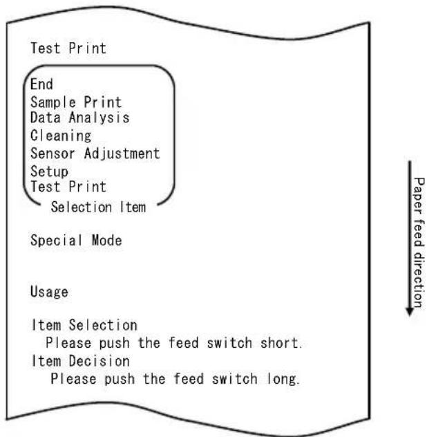
flowchart
graph TD
    A["Test Print"] --> B["End"]
    B --> C["Sample Print"]
    C --> D["Data Analysis"]
    D --> E["Cleaning"]
    E --> F["Sensor Adjustment"]
    F --> G["Setup"]
    G --> H["Test Print"]
    H --> I["Selection Item"]
    J["Special Mode"] --> K["Usage"]
    K --> L(Item Selection]
    L --> M["Please push the feed switch short."]
    L --> N(Item Decision]
    N --> O["Please push the feed switch long."]
    P["Paper feed direction"] --> Q
- Enter setup mode from special mode.
Press the FEED switch briefly (one second or less) once to move to "SETUP".
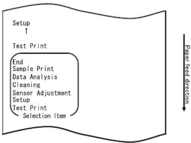
flowchart
graph TD
    A["Setup ↑"] --> B["Test Print"]
    B --> C["End Sample Print"]
    C --> D["Data Analysis"]
    D --> E["Cleaning"]
    E --> F["Sensor Adjustment"]
    F --> G["Setup"]
    G --> H["Test Print"]
    H --> I["Selection Item"]
    style A fill:#f9f,stroke:#333
    style B fill:#ccf,stroke:#333
    style C fill:#cfc,stroke:#333
    style D fill:#fcc,stroke:#333
    style E fill:#cff,stroke:#333
    style F fill:#ffc,stroke:#333
    style G fill:#cfc,stroke:#333
    style H fill:#fcc,stroke:#333
    style I fill:#ffc,stroke:#333
Then, press and hold down the FEED switch for one second or longer to accept the selection.
The printer prints the following when it enters setup mode:
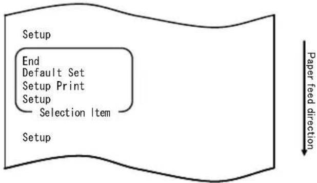
flowchart
graph TD
    A["Setup"] --> B["End"]
    B --> C["Default Set"]
    C --> D["Setup Print"]
    D --> E["Setup"]
    E --> F["Selection Item"]
    F --> G["Setup"]
    style A fill:#f9f,stroke:#333
    style G fill:#ccf,stroke:#333
    note right of G Paper feed direction
- In setup mode, select "SETUP".
Press and hold down the FEED switch for one second or longer to accept the selection.
The printer prints the following when you accept the selection of "SETUP":
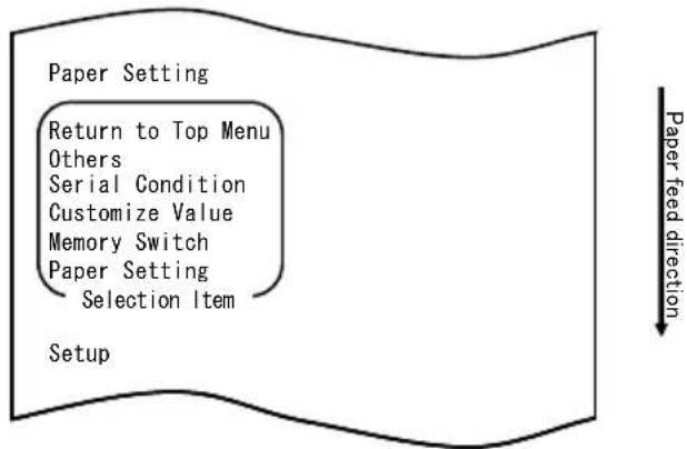
flowchart
graph TD
    A["Paper Setting"] --> B["Return to Top Menu"]
    B --> C["Others"]
    C --> D["Serial Condition"]
    D --> E["Customize Value"]
    E --> F["Memory Switch"]
    F --> G["Paper Setting"]
    G --> H["Selection Item"]
    I["Setup"] --> J["Paper feed direction"]
- Select "CUSTOMIZE VALUE" as your option.
Quickly press the FEED switch two times (up to one second each) to move to "CUSTOMIZE VALUE".
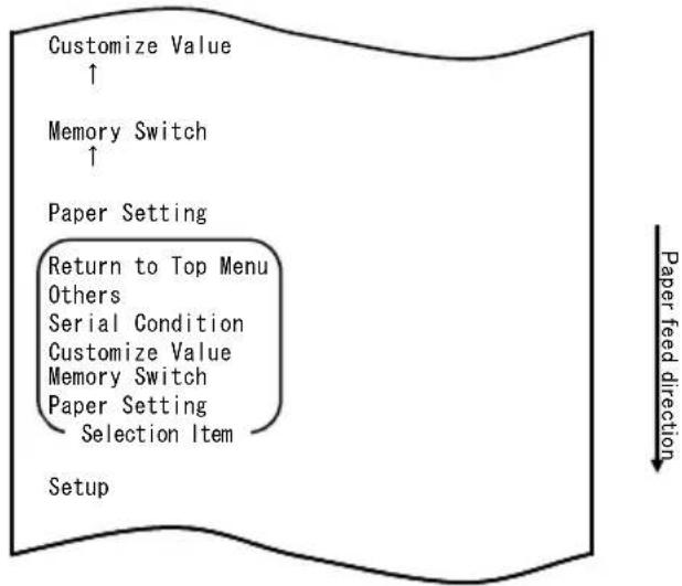
flowchart
graph TD
    A["Customize Value ↑"] --> B["Memory Switch ↑"]
    B --> C["Paper Setting"]
    C --> D["Return to Top Menu Others"]
    C --> E["Serial Condition"]
    C --> F["Customize Value"]
    C --> G["Memory Switch"]
    C --> H["Paper Setting"]
    H --> I["Selection Item"]
    J["Setup"] --> K["Paper feed direction ↓"]
The printer prints the following when you accept the selection of "CUSTOMIZE VALUE":
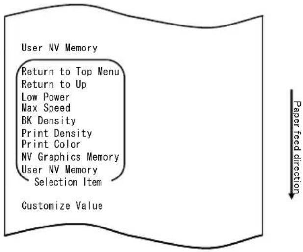
- Select "MAX SPEED" as your option.
Press the FEED switch briefly (one second or less) five times to move to "MAX SPEED".
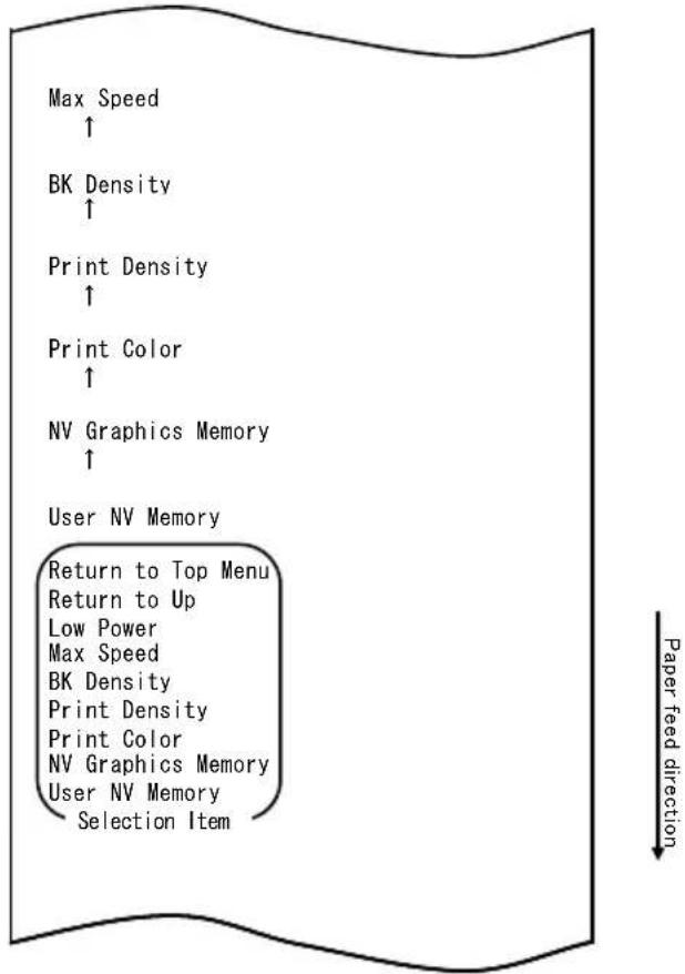
flowchart
graph TD
    A["Max Speed ↑"] --> B["BK Density ↑"]
    B --> C["Print Density ↑"]
    C --> D["Print Color ↑"]
    D --> E["NV Graphics Memory ↑"]
    E --> F["User NV Memory"]
    F --> G["Return to Top Menu"]
    G --> H["Return to Up"]
    H --> I["Low Power"]
    I --> J["Max Speed"]
    J --> K["BK Density"]
    K --> L["Print Density"]
    L --> M["Print Color"]
    M --> N["NV Graphics Memory"]
    N --> O["User NV Memory"]
    O --> P["Selection Item"]
Then, press and hold down the FEED switch for one second or longer to accept the selection. The printer prints the following when you accept the selection of "MAX SPEED":
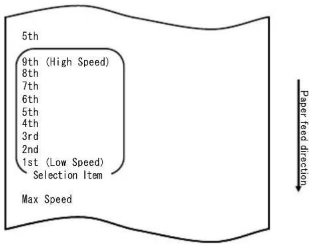
7. Select "9th" as your option.
Press the FEED switch briefly (one second or less) until "9th" is reached. Then, press and hold down the FEED switch for one second or longer to accept the selection.
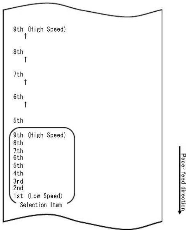
The printer prints the following when you accept the selection of "9th":
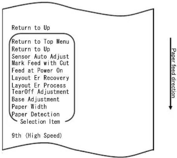
flowchart
graph TD
    A["Return to Top Menu"] --> B["Sensor Auto Adjust"]
    B --> C["Mark Feed with Cut"]
    C --> D["Feed at Power On"]
    D --> E["Layout Er Recovery"]
    E --> F["Layout Er Process"]
    F --> G["TearOff Adjustment"]
    G --> H["Base Adjustment"]
    H --> I["Paper Width"]
    I --> J["Paper Detection"]
    J --> K["Selection Item"]
    L["9th (High Speed)"] --> M["Paper feed direction"]
- Select "RETURN TO UP" as your option.
Press and hold down the FEED switch for one second or longer to accept the selection.
The printer prints the following when you accept the selection of "RETURN TO UP":
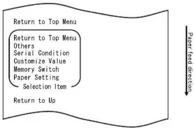
flowchart
graph TD
    A["Return to Top Menu"] --> B["Return to Top Menu"]
    B --> C["Others"]
    C --> D["Serial Condition"]
    D --> E["Customize Value"]
    E --> F["Memory Switch"]
    F --> G["Paper Setting"]
    G --> H["Selection Item"]
    H --> I["Return to Up"]
- Select "RETURN TO TOP MENU" as your option.
Press and hold down the FEED switch for one second or longer to accept the selection.
The printer prints the following when you accept the selection of "RETURN TO TOP MENU":
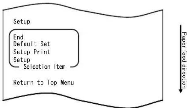
flowchart
graph TD
    A["Setup"] --> B["End"]
    B --> C["Default Set"]
    C --> D["Setup Print"]
    D --> E["Setup"]
    E --> F["Selection Item"]
    F --> G["Return to Top Menu"]
    H["Paper feed direction"] --> I["Downward arrow"]
- Select "END" as your option.
Press the FEED switch briefly (one second or less) three times to move to "END".
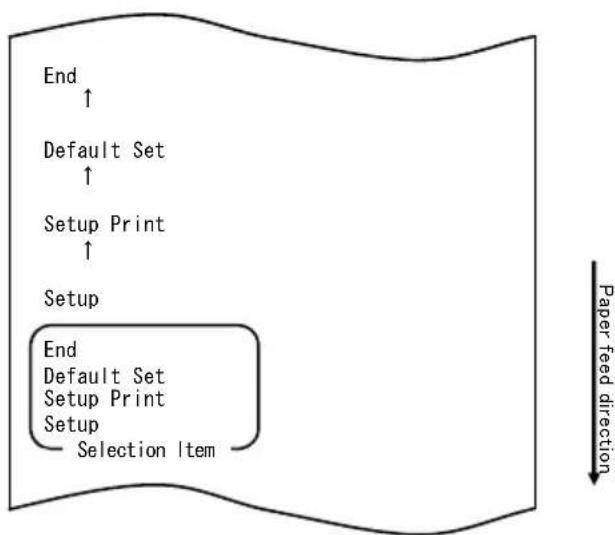
flowchart
graph TD
    A["End"] --> B["Default Set"]
    B --> C["Setup Print"]
    C --> D["Setup"]
    D --> E["End"]
    E --> F["Default Set"]
    F --> G["Setup Print"]
    G --> H["Setup"]
    H --> I["Selection Item"]
    style A fill:#f9f,stroke:#333
    style B fill:#f9f,stroke:#333
    style C fill:#f9f,stroke:#333
    style D fill:#f9f,stroke:#333
    style E fill:#f9f,stroke:#333
    style F fill:#f9f,stroke:#333
    style G fill:#f9f,stroke:#333
    style H fill:#f9f,stroke:#333
    style I fill:#f9f,stroke:#333
Then, press and hold down the FEED switch for one second or longer to accept the selection.
The printer cuts the paper and exits from setup mode when you accept the selection of "END".
Note: If you turn off the printer power switch without first selecting "END", your setting will be lost.
- Verifying your setting
To verify your setting, execute a test print, referring to Section 10-1. The test printing prints a list of printer settings. Check the list, and verify your setting.
Example (3): Changing the Print Color
Change of the print color setting (from monochrome to two colors)
The procedure for this setting is as follows.
- Before starting work for this setting, verify the following conditions of the printer:
(1) The power is off.
(2) Roll paper is inserted in it.
(3) The cover is closed.
- Enter special mode.
Turn on the power switch on the right side of the printer while holding down the FEED switch on the left part of the Top cover.
Note: You must hold down the FEED switch until the printer starts printing.
Note: If you have passed the item that you want to select, quickly press the FEED switch repeatedly until you return to the first item.
The printer prints the following when it enters special mode
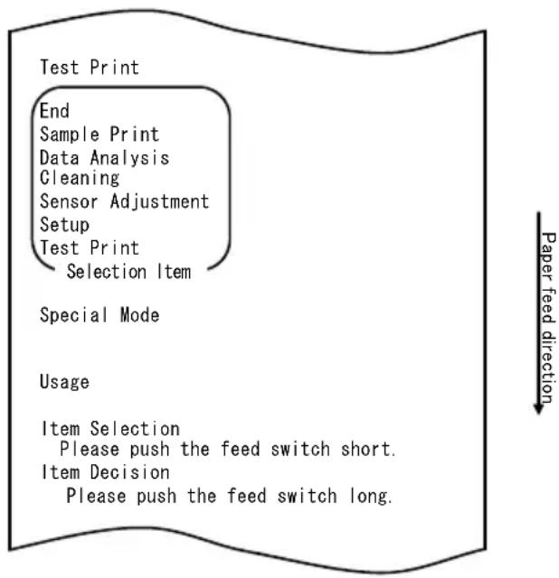
flowchart
graph TD
    A["Test Print"] --> B["End"]
    B --> C["Sample Print"]
    C --> D["Data Analysis"]
    D --> E["Cleaning"]
    E --> F["Sensor Adjustment"]
    F --> G["Setup"]
    G --> H["Test Print"]
    H --> I["Selection Item"]
    J["Special Mode"] --> K["Usage"]
    L["Item Selection"] --> M["Please push the feed switch short."]
    N["Item Decision"] --> O["Please push the feed switch long."]
    P["Paper feed direction"] --> Q
- Enter setup mode from special mode.
Press the FEED switch briefly (one second or less) once to move to "SETUP".
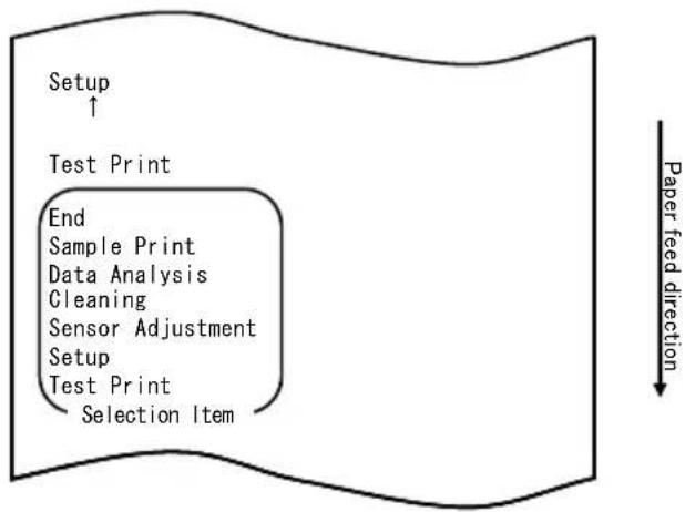
flowchart
graph TD
    A["Setup ↑"] --> B["Test Print"]
    B --> C["End"]
    C --> D["Sample Print"]
    C --> E["Data Analysis"]
    C --> F["Gleaning"]
    C --> G["Sensor Adjustment"]
    C --> H["Setup"]
    H --> I["Test Print"]
    I --> J["Selection Item"]
    style A fill:#f9f,stroke:#333
    style B fill:#ccf,stroke:#333
    style C fill:#cfc,stroke:#333
    style D fill:#fcc,stroke:#333
    style E fill:#cff,stroke:#333
    style F fill:#ffc,stroke:#333
    style G fill:#cfc,stroke:#333
    style H fill:#fcc,stroke:#333
    style I fill:#cfc,stroke:#333
    style J fill:#fcc,stroke:#333
Then, press and hold down the FEED switch for one second or longer to accept the selection.
The printer prints the following when it enters setup mode:
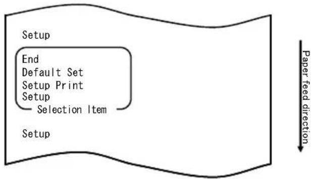
flowchart
graph TD
    A["Setup"] --> B["End"]
    B --> C["Default Set"]
    C --> D["Setup Print"]
    D --> E["Setup"]
    E --> F["Selection Item"]
    F --> G["Paper feed direction"]
- In setup mode, select "SETUP".
Press and hold down the FEED switch for one second or longer to accept the selection.
The printer prints the following when you accept the selection of "SETUP":
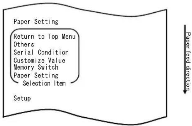
flowchart
graph TD
    A["Paper Setting"] --> B["Return to Top Menu"]
    B --> C["Others"]
    C --> D["Serial Condition"]
    D --> E["Customize Value"]
    E --> F["Memory Switch"]
    F --> G["Paper Setting"]
    G --> H["Selection Item"]
    I["Setup"] --> J["Paper feed direction"]
- Select "CUSTOMIZE VALUE" as your option.
Press the FEED switch briefly (one second or less) twice to move to "CUSTOMIZE VALUE".
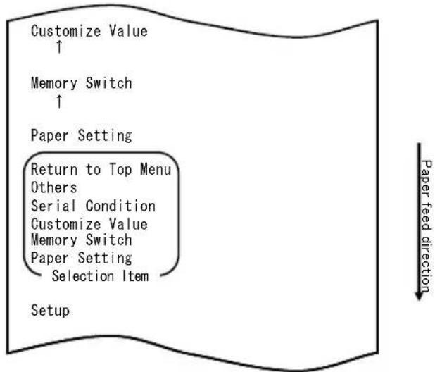
flowchart
graph TD
    A["Customize Value ↑"] --> B["Memory Switch ↑"]
    B --> C["Paper Setting"]
    C --> D["Return to Top Menu Others"]
    C --> E["Serial Condition"]
    C --> F["Customize Value"]
    C --> G["Memory Switch"]
    C --> H["Paper Setting"]
    H --> I["Selection Item"]
    J["Setup"] --> K["Paper feed direction ↓"]
Then, press and hold down the FEED switch for one second or longer to accept the selection.
The printer prints the following when you accept the selection of "CUSTOMIZE VALUE":
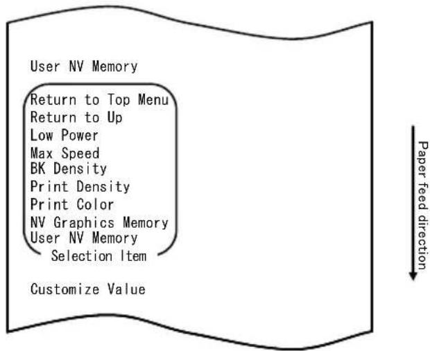
- Select "PRINT COLOR" as your option.
Press the FEED switch briefly (one second or less) twice to move to "PRINT COLOR".
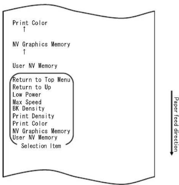
flowchart
graph TD
    A["Print Color ↑"] --> B["NV Graphics Memory ↑"]
    B --> C["User NV Memory"]
    C --> D["Return to Top Menu"]
    D --> E["Return to Up"]
    E --> F["Low Power"]
    F --> G["Max Speed"]
    G --> H["BK Density"]
    H --> I["Print Density"]
    I --> J["Print Color"]
    J --> K["NV Graphics Memory"]
    K --> L["User NV Memory"]
    L --> M["Selection Item"]
Then, press and hold down the FEED switch for one second or longer to accept the selection.
The printer prints the following when you accept the selection of "PRINT COLOR":
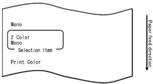
- Select "2 COLOR" as your option.
Press the FEED switch briefly (one second or less) once to move to "2 COLOR".
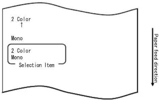
The printer prints the following when you accept the selection of "2 COLOR":
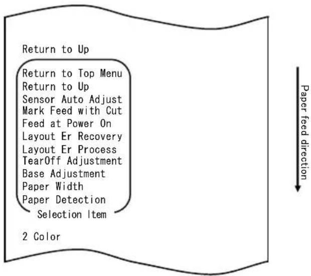
- Select "RETURN TO UP" as your option.
Press and hold down the FEED switch for one second or longer to accept the selection.
The printer prints the following when you accept the selection of "RETURN TO UP":
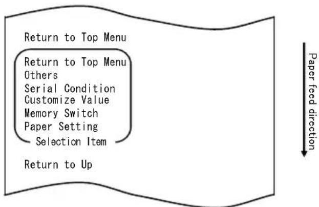
flowchart
graph TD
    A["Return to Top Menu"] --> B["Return to Top Menu"]
    B --> C["Others"]
    C --> D["Serial Condition"]
    D --> E["Customize Value"]
    E --> F["Memory Switch"]
    F --> G["Paper Setting"]
    G --> H["Selection Item"]
    H --> I["Return to Up"]
    style A fill:#f9f,stroke:#333
    style I fill:#ccf,stroke:#333
- Select "RETURN TO TOP MENU" as your option.
Press and hold down the FEED switch for one second or longer to accept the selection.
The printer prints the following when you accept the selection of "RETURN TO TOP MENU":
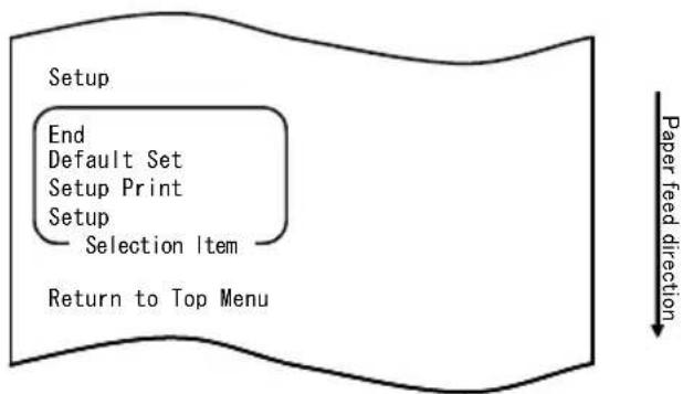
flowchart
graph TD
    A["Setup"] --> B["End"]
    B --> C["Default Set"]
    C --> D["Setup Print"]
    D --> E["Setup"]
    E --> F["Selection Item"]
    F --> G["Return to Top Menu"]
    H["Paper feed direction"] --> I["Downward arrow"]
- Select "END" as your option.
Press the FEED switch briefly (one second or less) three times to move to "END".
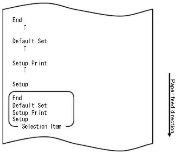
flowchart
graph TD
    A["End"] --> B["Default Set"]
    B --> C["Setup Print"]
    C --> D["Setup"]
    D --> E["End"]
    style D fill:#f9f,stroke:#333
    note right of E "Selection Item"
    note right of F "Paper feed direction"
Note: If you turn off the printer power switch without first selecting "END", your settings will be lost.
- Verifying your setting
To verify your setting, execute a test print, referring to Section 10-1. The test printing prints a list of printer settings. Check the list, and verify your setting.
Example (4) Changing the Feed at Power On
Change from ENABLE to DISABLE
The procedure for this setting is as follows:
- Before starting work for this setting, verify the following printer conditions:
(1) The power is turned off.
(2) Paper is loaded on the printer.
(3) The cover is closed.
- Enter special mode.
Turn on the power switch on the right side of the printer while holding down the FEED switch on the left part of the top cover.
Note: You must hold down the FEED switch until the printer starts printing.
Note: If you have passed the item that you want to select, quickly press the FEED switch repeatedly until you return to the first item.
The printer prints the following when entering special mode:

flowchart
graph TD
    A["Test Print"] --> B["End"]
    B --> C["Sample Print"]
    C --> D["Data Analysis"]
    D --> E["Cleaning"]
    E --> F["Sensor Adjustment"]
    F --> G["Setup"]
    G --> H["Test Print"]
    H --> I["Selection Item"]
    J["Special Mode"] --> K["Usage"]
    K --> L(Item Selection]
    L --> M["Please push the feed switch short."]
    L --> N(Item Decision]
    N --> O["Please push the feed switch long."]
    P["Paper feed direction"] --> Q
- Enter setup mode from special mode.
Quickly press the FEED switch (up to one second) to move to "SETUP".
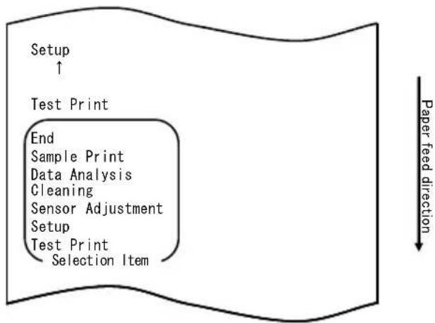
flowchart
graph TD
    A["Setup ↑"] --> B["Test Print"]
    B --> C["End"]
    C --> D["Sample Print"]
    C --> E["Data Analysis"]
    C --> F["Cleaning"]
    C --> G["Sensor Adjustment"]
    C --> H["Setup"]
    H --> I["Test Print"]
    I --> J["Selection Item"]
    style A fill:#f9f,stroke:#333
    style B fill:#ccf,stroke:#333
    style C fill:#cfc,stroke:#333
    style D fill:#fcc,stroke:#333
    style E fill:#cff,stroke:#333
    style F fill:#ffc,stroke:#333
    style G fill:#cfc,stroke:#333
    style H fill:#fcc,stroke:#333
    style I fill:#cfc,stroke:#333
    style J fill:#fcc,stroke:#333
Then press and hold down the FEED switch for at least one second to accept the selection.
The printer prints the following when entering setup mode:

flowchart
graph TD
    A["Setup"] --> B["End"]
    B --> C["Default Set"]
    C --> D["Setup Print"]
    D --> E["Setup"]
    E --> F["Selection Item"]
    F --> G["Paper feed direction"]
- In setup mode, select "SETUP".
Press and hold down the FEED switch for at least one second to accept the selection.
The printer prints the following upon your acceptance of "SETUP" selection:

flowchart
graph TD
    A["Paper Setting"] --> B["Return to Top Menu"]
    B --> C["Others"]
    C --> D["Serial Condition"]
    D --> E["Customize Value"]
    E --> F["Memory Switch"]
    F --> G["Paper Setting"]
    G --> H["Selection Item"]
    I["Setup"] --> J["Paper feed direction"]
- Select "PAPER SETTING" as your option.
Press and hold down the FEED switch for at least one second to accept the selection.
The printer prints the following upon your acceptance of "PAPER SETTING"
selection:
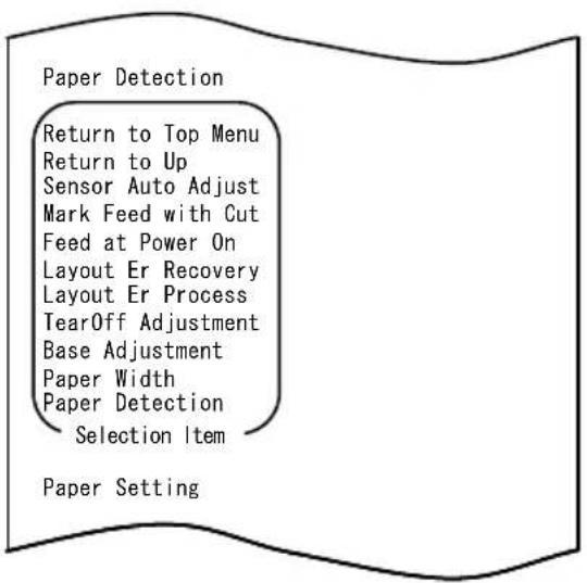
Paper feed direction
- Select "FEED AT POWER ON" as your option.
Quickly press the FEED switch five times (up to one second each) to move to "FEED AT POWER ON".
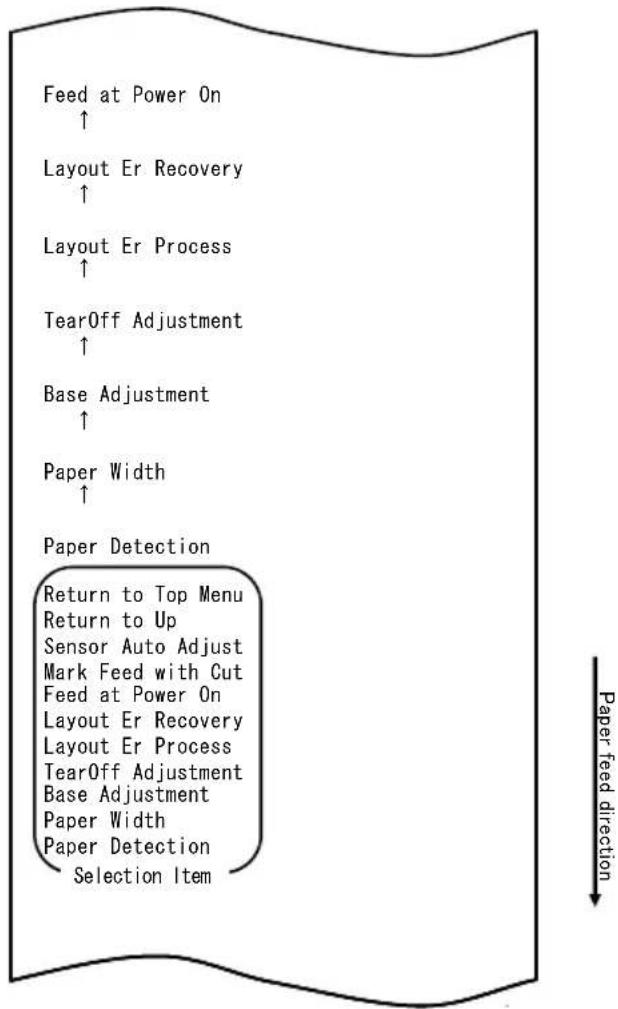
flowchart
graph TD
    A["Feed at Power On ↑"] --> B["Layout Er Recovery ↑"]
    B --> C["Layout Er Process ↑"]
    C --> D["TearOff Adjustment ↑"]
    D --> E["Base Adjustment ↑"]
    E --> F["Paper Width ↑"]
    F --> G["Paper Detection"]
    G --> H["Return to Top Menu"]
    H --> I["Return to Up"]
    I --> J["Sensor Auto Adjust"]
    J --> K["Mark Feed with Cut"]
    K --> L["Feed at Power On"]
    L --> M["Layout Er Recovery"]
    M --> N["Layout Er Process"]
    N --> O["TearOff Adjustment"]
    O --> P["Base Adjustment"]
    P --> Q["Paper Width"]
    Q --> R["Paper Detection"]
    R --> S["Selection Item"]
Then press and hold down the FEED switch for at least one second to accept the selection.
The printer prints the following upon your acceptance of "FEED AT POWER ON" selection:
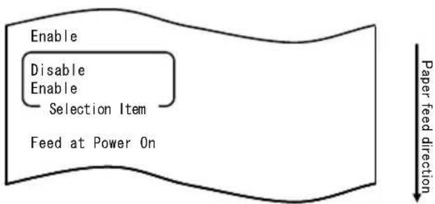
flowchart
graph TD
    A["Enable"] --> B["Disable"]
    A --> C["Enable"]
    D["Selection Item"] --> E["Feed at Power On"]
    F["Paper feed direction"] --> G["Downward arrow"]
- Select "DISABLE" as your option.
Quickly press the FEED switch (up to one second) to move to "DISABLE".
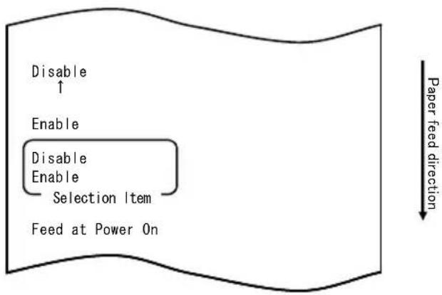
flowchart
graph TD
    A["Disable ↑"] --> B["Enable"]
    B --> C["Disable Enable Selection Item"]
    C --> D["Feed at Power On"]
    E["Paper feed direction"] --> F["-->"]
Then press and hold down the FEED switch for at least one second to accept the selection.
The printer prints the following upon your acceptance of "DISABLE" selection:
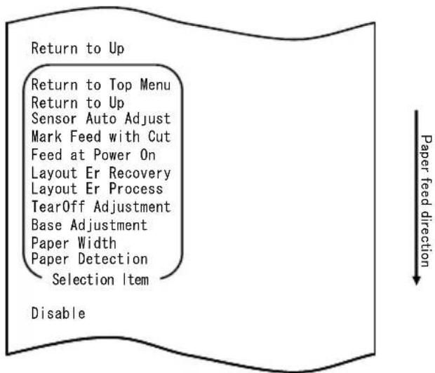
flowchart
graph TD
    A["Return to Up"] --> B["Return to Top Menu"]
    B --> C["Return to Up"]
    C --> D["Sensor Auto Adjust"]
    C --> E["Mark Feed with Cut"]
    C --> F["Feed at Power On"]
    C --> G["Layout Er Recovery"]
    C --> H["Layout Er Process"]
    C --> I["TearOff Adjustment"]
    C --> J["Base Adjustment"]
    C --> K["Paper Width"]
    C --> L["Paper Detection"]
    C --> M["Selection Item"]
    N["Disable"] --> O["Paper feed direction"]
- Select "RETURN TO UP" as your option.
Press and hold down the FEED switch for at least one second to accept the selection.
The printer prints the following upon your acceptance of "RETURN TO UP" selection:
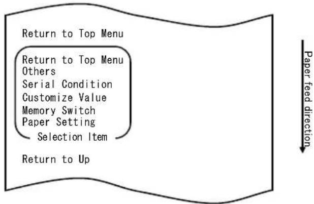
flowchart
graph TD
    A["Return to Top Menu"] --> B["Return to Top Menu\nOthers"]
    B --> C["Serial Condition"]
    C --> D["Customize Value"]
    D --> E["Memory Switch"]
    E --> F["Paper Setting"]
    F --> G["Selection Item"]
    G --> H["Return to Up"]
    style A fill:#f9f,stroke:#333
    style H fill:#f9f,stroke:#333
    note right of H "Paper feed direction"
- Select "RETURN TO TOP MENU" as your option.
Press and hold down the FEED switch for at least one second to accept the selection.
The printer prints the following upon your acceptance of "RETURN TO TOP MENU" selection:
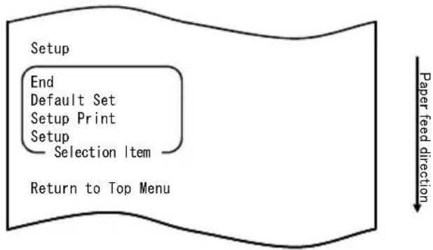
flowchart
graph TD
    A["Setup"] --> B["End"]
    B --> C["Default Set"]
    C --> D["Setup Print"]
    D --> E["Setup"]
    E --> F["Selection Item"]
    F --> G["Return to Top Menu"]
    H["Paper feed direction"] --> I["↓"]
- Select "END" as your option.
Quickly press the FEED switch three times (up to one second each) to move to "END".
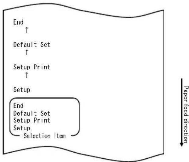
flowchart
graph TD
    A["End"] --> B["Default Set"]
    B --> C["Setup Print"]
    C --> D["Setup"]
    D --> E["End\nDefault Set\nSetup Print\nSetup\nSelection Item"]
    style A fill:#f9f,stroke:#333
    style B fill:#f9f,stroke:#333
    style C fill:#f9f,stroke:#333
    style D fill:#f9f,stroke:#333
    style E fill:#f9f,stroke:#333
    note right of E Paper feed direction
Then press and hold down the FEED switch for at least one second to accept the selection.
After you accept "END" selection, the printer cuts the paper and exits from setup mode.
Note: If you turn off the printer power switch without first selecting "END", your settings will be lost.
- Verifying your settings
To verify your settings, execute a test print as described in Section 10-1.
The test printing prints a list of printer settings. Check the list to verify your settings.
Example (5) Initializing the printer settings
Note on initialization
The initialization procedure does not initialize the paper width and sensor adjustments.
These values will remain as set the paper layout information will be initialized except for the paper width.
The initialization procedure is as follows:
- Before starting work for this setting, verify the following printer conditions:
(1) The power is turned off.
(2) Paper is loaded on the printer.
(3) The cover is closed.
- Enter special mode.
Turn on the power switch on the right side of the printer while holding down the FEED switch on the left part of the top cover.
Note: You must hold down the FEED switch until the printer starts printing.
Note: If you have passed the item that you want to select, quickly press the FEED switch repeatedly until you return to the first item.
The printer prints the following when entering special mode:
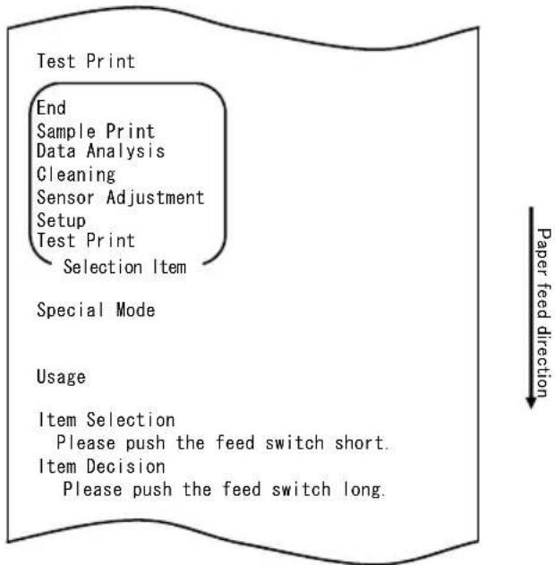
flowchart
graph TD
    A["Test Print"] --> B["End"]
    B --> C["Sample Print"]
    C --> D["Data Analysis"]
    D --> E["Cleaning"]
    E --> F["Sensor Adjustment"]
    F --> G["Setup"]
    G --> H["Test Print"]
    H --> I["Selection Item"]
    J["Special Mode"] --> K["Usage"]
    K --> L(Item Selection]
    L --> M["Please push the feed switch short."]
    L --> N(Item Decision]
    N --> O["Please push the feed switch long."]
    P["Paper feed direction"] --> Q
- Enter setup mode from special mode.
Quickly press the FEED switch (up to one second) to move to "SETUP".
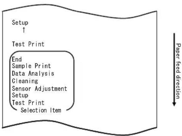
flowchart
graph TD
    A["Setup ↑"] --> B["Test Print"]
    B --> C["End Sample Print\nData Analysis\nCleaning\nSensor Adjustment\nSetup\nTest Print\nSelection Item"]
    C --> D["Paper feed direction"]
Then press and hold down the FEED switch for at least one second to accept the selection.
The printer prints the following when entering setup mode:
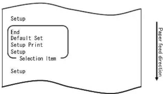
flowchart
graph TD
    A["Setup"] --> B["End"]
    B --> C["Default Set"]
    C --> D["Setup Print"]
    D --> E["Setup"]
    E --> F["Selection Item"]
    F --> G["Setup"]
    style A fill:#f9f,stroke:#333
    style G fill:#ccf,stroke:#333
- In setup mode, select "DEFAULT SET".
Quickly press the FEED switch twice (up to one second each) to move to "DEFAULT SET".
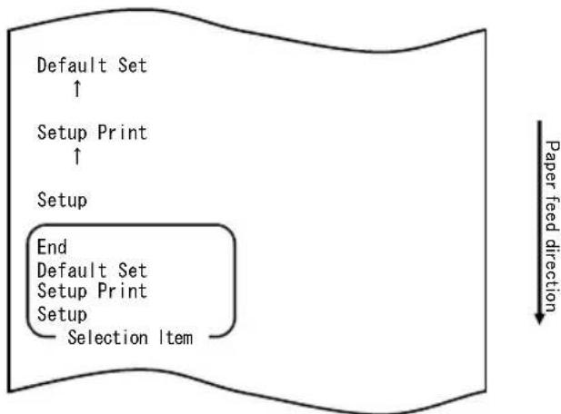
flowchart
graph TD
    A["Default Set ↑"] --> B["Setup Print ↑"]
    B --> C["Setup"]
    C --> D["End"]
    D --> E["Default Set Setup Print Setup Selection Item"]
    style D fill:#f9f,stroke:#333
    note right of D Paper feed direction
- Select "DEFAULT SET" as your option.
Press and hold down the FEED switch for at least one second to accept the selection.
The printer prints the following upon your acceptance of "DEFAULT SET" selection:
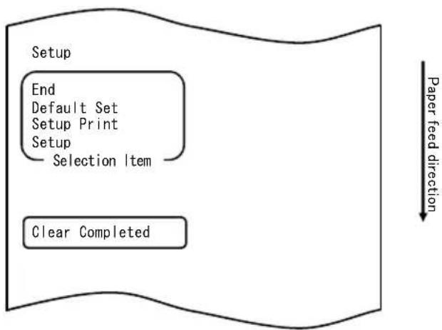
flowchart
graph TD
    A["Setup"] --> B["End"]
    B --> C["Default Set"]
    C --> D["Setup Print"]
    D --> E["Setup"]
    E --> F["Selection Item"]
    F --> G["Clear Completed"]
    G --> H["Paper feed direction"]
Note: If you turn off the printer power switch without first selecting "END", your settings will be lost.
- Verifying your settings
To verify your settings, execute a test print as described in Section 10-1. The test printing prints a list of printer settings. Check the list to verify your settings.
The procedure for this setting change is as follows:
- Before starting work for this setting, verify the following printer conditions:
(1) The power is turned off.
(2) Paper is loaded on the printer.
(3) The cover is closed.
- Enter special mode.
Turn on the power switch on the right side of the printer while holding down the FEED switch on the left part of the top cover.
Note: You must hold down the FEED switch until the printer starts printing.
Note: If you have passed the item that you want to select, quickly press the FEED switch repeatedly until you return to the first item.
The printer prints the following when entering special mode:
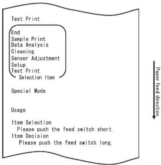
flowchart
graph TD
    A["Test Print"] --> B["End"]
    B --> C["Sample Print"]
    C --> D["Data Analysis"]
    D --> E["Cleaning"]
    E --> F["Sensor Adjustment"]
    F --> G["Setup"]
    G --> H["Test Print"]
    H --> I["Selection Item"]
    J["Special Mode"] --> K["Usage"]
    K --> L(Item Selection]
    L --> M["Please push the feed switch short."]
    L --> N(Item Decision]
    N --> O["Please push the feed switch long."]
    P["Paper feed direction"] --> Q
- Enter setup mode from special mode.
Quickly press the FEED switch (up to one second) to move to "SETUP".
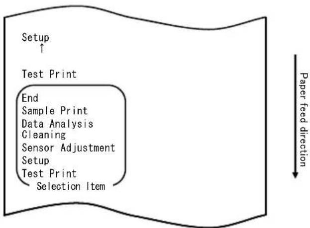
flowchart
graph TD
    A["Setup ↑"] --> B["Test Print"]
    B --> C["End"]
    C --> D["Sample Print"]
    C --> E["Data Analysis"]
    C --> F["Cleaning"]
    C --> G["Sensor Adjustment"]
    C --> H["Setup"]
    H --> I["Test Print"]
    I --> J["Selection Item"]
    style A fill:#f9f,stroke:#333
    style B fill:#ccf,stroke:#333
    style C fill:#cfc,stroke:#333
    style D fill:#fcc,stroke:#333
    style E fill:#cff,stroke:#333
    style F fill:#ffc,stroke:#333
    style G fill:#cfc,stroke:#333
    style H fill:#fcc,stroke:#333
    style I fill:#cfc,stroke:#333
    style J fill:#fcc,stroke:#333
Then press and hold down the FEED switch for at least one second to accept the selection.
The printer prints the following when entering setup mode:
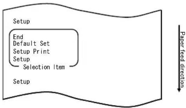
flowchart
graph TD
    A["Setup"] --> B["End"]
    B --> C["Default Set"]
    C --> D["Setup Print"]
    D --> E["Setup"]
    E --> F["Selection Item"]
    F --> G["Paper feed direction"]
- In setup mode, select "SETUP".
Press and hold down the FEED switch for at least one second to accept the selection.
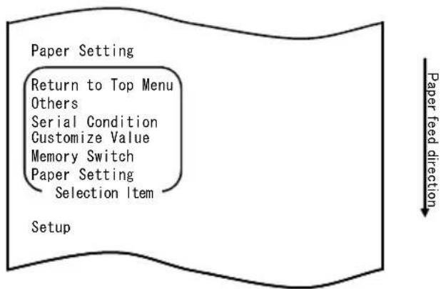
flowchart
graph TD
    A["Paper Setting"] --> B["Return to Top Menu"]
    B --> C["Others"]
    C --> D["Serial Condition"]
    D --> E["Customize Value"]
    E --> F["Memory Switch"]
    F --> G["Paper Setting"]
    G --> H["Selection Item"]
    I["Setup"] --> J["Paper feed direction"]
- Select "OTHERS" as your option.
Quickly press the FEED switch four times (up to one second each) to move to "OTHERS".
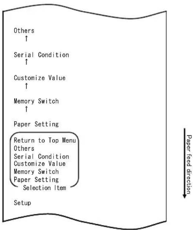
flowchart
graph TD
    A["Setup"] --> B["Return to Top Menu"]
    B --> C["Other"]
    C --> D["Serial Condition"]
    D --> E["Customize Value"]
    E --> F["Memory Switch"]
    F --> G["Paper Setting"]
    G --> H["Selection Item"]
    H --> I["Paper Feed Direction"]
    I --> J["Customize Value"]
    J --> K["Customize Value"]
    K --> L["Customize Value"]
    L --> M["Customize Value"]
    M --> N["Customize Value"]
    N --> O["Customize Value"]
    O --> P["Customize Value"]
    P --> Q["Customize Value"]
    Q --> R["Customize Value"]
    R --> S["Customize Value"]
    S --> T["Customize Value"]
    T --> U["Customize Value"]
    U --> V["Customize Value"]
    V --> W["Customize Value"]
    W --> X["Customize Value"]
    X --> Y["Customize Value"]
    Y --> Z["Customize Value"]
    Z --> AA["Customize Value"]
    AA --> AB["Customize Value"]
    AB --> AC["Customize Value"]
    AC --> AD["Customize Value"]
    AD --> AE["Customize Value"]
    AE --> AF["Customize Value"]
    AF --> AG["Customize Value"]
    AG --> AH["Customize Value"]
    AH --> AI["Customize Value"]
    AI --> AJ["Customize Value"]
    AJ --> AK["Customize Value"]
    AK --> AL["Customize Value"]
    AL --> AM["Customize Value"]
    AM --> AN["Customize Value"]
    AN --> AO["Customize Value"]
    AO --> AP["Customize Value"]
    AP --> AQ["Customize Value"]
    AQ --> AR["Customize Value"]
    AR --> AS["Customize Value"]
    AS --> AT["Customize Value"]
    AT --> AU["Customize Value"]
    AU --> AV["Customize Value"]
    AV --> AW["Customize Value"]
    AW --> AX["Customize Value"]
    AX --> AY["Customize Value"]
    AY --> AZ["Customize Value"]
    AZ --> BA["Customize Value"]
    BA --> BB["Customize Value"]
    BB --> BC["Customize Value"]
    BC --> BD["Customize Value"]
    BD --> BE["Customize Value"]
    BE --> BF["Customize Value"]
    BF --> BG["Customize Value"]
    BG --> BH["Customize Value"]
    BH --> BI["Customize Value"]
    BI --> BJ["Customize Value"]
    BJ --> BK["Customize Value"]
    BK --> BL["Customize Value"]
    BL --> BM["Customize Value"]
    BM --> BN["Customize Value"]
    BN --> BO["Customize Value"]
    BO --> BP["Customize Value"]
    BP --> BQ["Customize Value"]
    BQ --> BR["Customize Value"]
    BR --> BS["Customize Value"]
    BS --> BT["Customize Value"]
    BT --> BU["Customize Value"]
    BU --> BV["Customize Value"]
    BV --> BW["Customize Value"]
    BW --> BX["Customize Value"]
    BX --> BY["Customize Value"]
    BY --> BZ["Customize Value"]
Then press and hold down the FEED switch for at least one second to accept the selection.
The printer prints the following upon your acceptance of "OTHERS" selection:
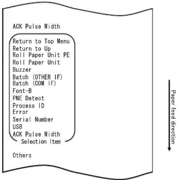
- Select "PNE DETECT" as your option.
Quickly press the FEED switch five times (up to one second each) to move to "PNE DETECT".
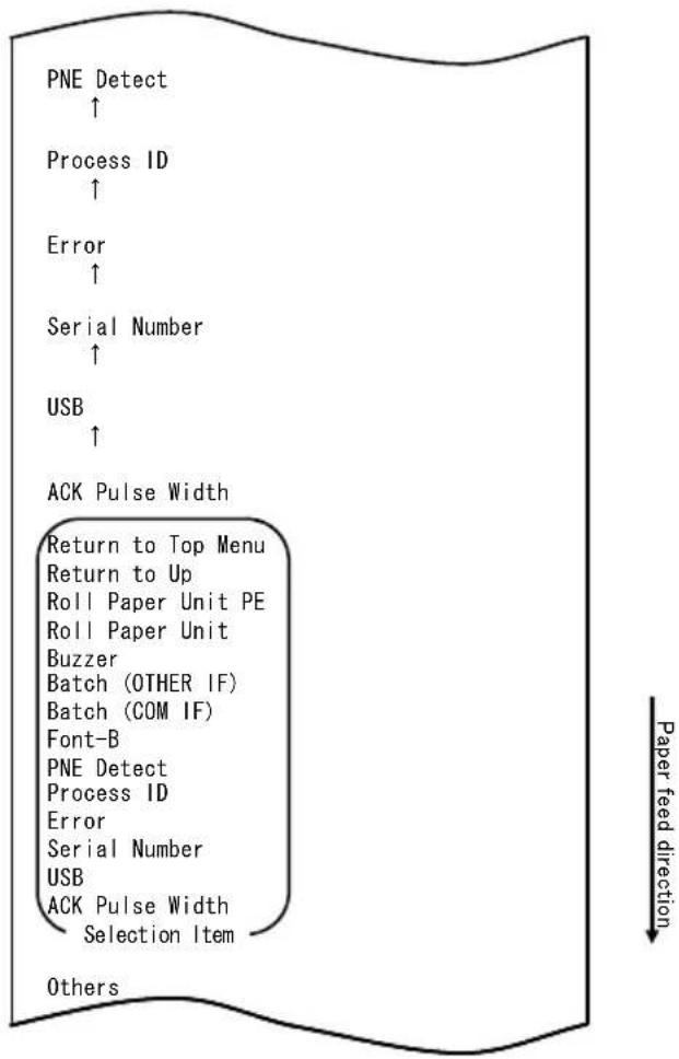
flowchart
graph TD
    A["PNE Detect ↑"] --> B["Process ID ↑"]
    B --> C["Error ↑"]
    C --> D["Serial Number ↑"]
    D --> E["USB ↑"]
    E --> F["ACK Pulse Width"]
    F --> G["Return to Top Menu"]
    G --> H["Return to Up"]
    H --> I["Roll Paper Unit PE"]
    I --> J["Roll Paper Unit"]
    J --> K["Buzzer"]
    K --> L["Batch (OTHER IF)"]
    L --> M["Batch (COM IF)"]
    M --> N["Font-B"]
    N --> O["PNE Detect"]
    O --> P["Process ID"]
    P --> Q["Error"]
    Q --> R["Serial Number"]
    R --> S["USB"]
    S --> T["ACK Pulse Width"]
    T --> U["Selection Item"]
    U --> V["Others"]
Press and hold down the FEED switch for at least one second to accept the selection.
The printer prints the following upon your acceptance of "PNE DETECT" selection:
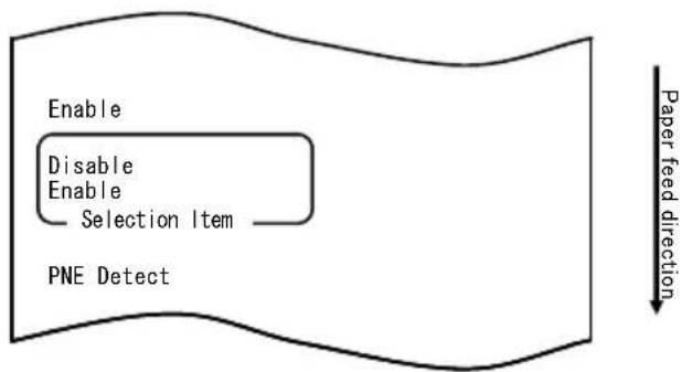
flowchart
graph TD
    A["Enable"] --> B["Disable"]
    B --> C["Enable"]
    C --> D["Selection Item"]
    D --> E["PNE Detect"]
    F["Paper feed direction"] --> G["End"]
- Select "DISABLE" as your option.
Quickly press the FEED switch (up to one second) to move to "DISABLE".
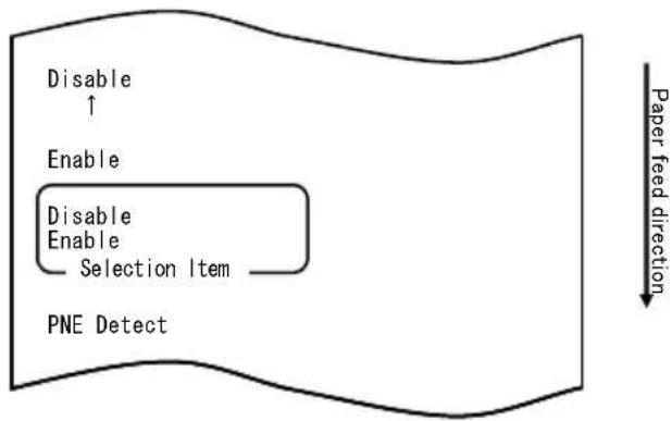
flowchart
graph TD
    A["Disable ↑"] --> B["Enable"]
    B --> C["Disable Enable Selection Item"]
    C --> D["PNE Detect"]
    E["Paper feed direction"] --> F
Press and hold down the FEED switch for at least one second to accept the selection.
The printer prints the following upon your acceptance of "DISABLE" selection:
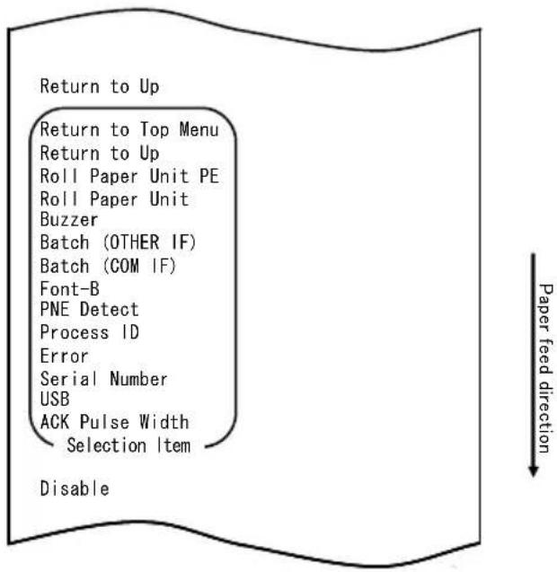
- Select "RETURN TO UP" as your option.
Press and hold down the FEED switch for at least one second to accept the selection.
The printer prints the following upon your acceptance of "RETURN TO UP" selection:

flowchart
graph TD
    A["Return to Top Menu"] --> B["Return to Top Menu"]
    B --> C["Others"]
    C --> D["Serial Condition"]
    D --> E["Customize Value"]
    E --> F["Memory Switch"]
    F --> G["Paper Setting"]
    G --> H["Selection Item"]
    H --> I["Return to Up"]
    I --> J["Paper feed direction"]
- Select "RETURN TO TOP MENU" as your option.
Press and hold down the FEED switch for at least one second to accept the selection.
The printer prints the following upon your acceptance of "RETURN TO TOP MENU" selection:

flowchart
graph TD
    A["Setup"] --> B["End"]
    B --> C["Default Set"]
    C --> D["Setup Print"]
    D --> E["Setup"]
    E --> F["Selection Item"]
    F --> G["Return to Top Menu"]
    H["Paper feed direction"] --> I["Downward arrow"]
- Select "END" as your option.
Quickly press the FEED switch three times (up to one second each) to move to "END".
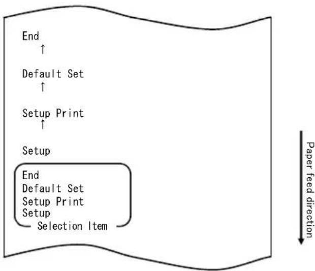
flowchart
graph TD
    A["End"] --> B["Default Set"]
    B --> C["Setup Print"]
    C --> D["Setup"]
    D --> E["End"]
    style D fill:#f9f,stroke:#333
    note right of D Paper feed direction
Then press and hold down the FEED switch for at least one second to accept the selection.
After you accept "END" selection, the printer cuts the paper and exits from setup mode.
Note: If you turn off the printer power switch without first selecting "END", your settings will be lost.
- Verifying your settings
To verify your settings, execute a test print as described in Section 10-1. The test printing prints a list of printer settings. Check the list to verify your settings.
Example (7) Changing the Paper Width
Change from 70 mm to 80 mm
The procedure for this setting change is as follows:
- Before starting work for this setting, verify the following printer conditions:
(1) The power is turned off.
(2) Paper is loaded on the printer.
(3) The cover is closed.
- Enter special mode.
Turn on the power switch on the right side of the printer while holding down the FEED switch on the left part of the top cover.
Note: You must hold down the FEED switch until the printer starts printing.
Note: If you have passed the item that you want to select, quickly press the FEED switch repeatedly until you return to the first item.
The printer prints the following when entering special mode:

flowchart
graph TD
    A["Test Print"] --> B["End"]
    B --> C["Sample Print"]
    C --> D["Data Analysis"]
    D --> E["Cleaning"]
    E --> F["Sensor Adjustment"]
    F --> G["Setup"]
    G --> H["Test Print"]
    H --> I["Selection Item"]
    J["Special Mode"] --> K["Usage"]
    K --> L(Item Selection]
    L --> M["Please push the feed switch short."]
    L --> N(Item Decision]
    N --> O["Please push the feed switch long."]
    P["Paper feed direction"] --> Q
- Enter setup mode from special mode.
Quickly press the FEED switch (up to one second) to move to "SETUP".
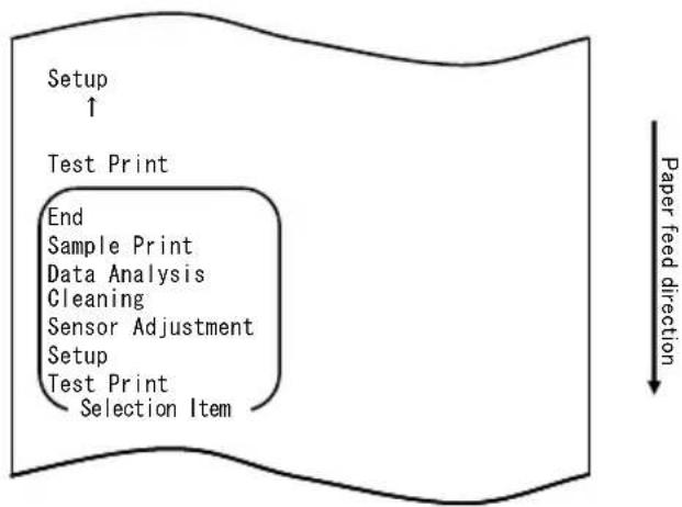
flowchart
graph TD
    A["Setup ↑"] --> B["Test Print"]
    B --> C["End Sample Print Data Analysis Cleaning Sensor Adjustment Setup Test Print Selection Item"]
    C --> D["Paper feed direction"]
Then press and hold down the FEED switch for at least one second to accept the selection.
The printer prints the following when entering setup mode:
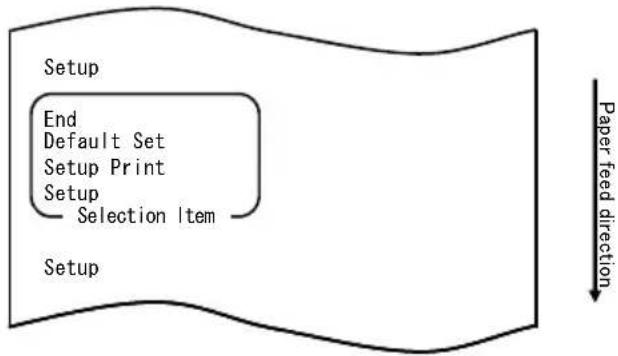
flowchart
graph TD
    A["Setup"] --> B["End"]
    B --> C["Default Set"]
    C --> D["Setup Print"]
    D --> E["Setup"]
    E --> F["Selection Item"]
    F --> G["Paper feed direction"]
- In setup mode, select "SETUP".
Press and hold down the FEED switch for at least one second to accept the selection.
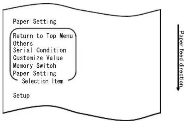
flowchart
graph TD
    A["Paper Setting"] --> B["Return to Top Menu"]
    B --> C["Others"]
    C --> D["Serial Condition"]
    D --> E["Customize Value"]
    E --> F["Memory Switch"]
    F --> G["Paper Setting"]
    G --> H["Selection Item"]
    I["Setup"] --> J["Paper feed direction"]
- Select "PAPER SETUP" as your option.
Press and hold down the FEED switch for at least one second to accept the selection.
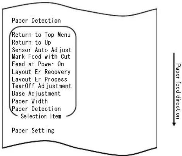
flowchart
graph TD
    A["Paper Detection"] --> B["Return to Top Menu"]
    B --> C["Return to Up"]
    C --> D["Sensor Auto Adjust"]
    D --> E["Mark Feed with Cut"]
    E --> F["Feed at Power On"]
    F --> G["Layout Er Recovery"]
    G --> H["Layout Er Process"]
    H --> I["TearOff Adjustment"]
    I --> J["Base Adjustment"]
    J --> K["Paper Width"]
    K --> L["Paper Detection"]
    L --> M["Selection Item"]
    M --> N["Paper Setting"]
- Select "PAPER WIDTH" as your option.
Quickly press the FEED switch (up to one second) to move to "PAPER WIDTH".
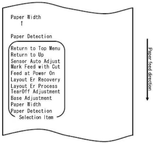
flowchart
graph TD
    A["Paper Width ↑"] --> B["Return to Top Menu"]
    B --> C["Return to Up"]
    C --> D["Sensor Auto Adjust"]
    D --> E["Mark Feed with Cut"]
    E --> F["Feed at Power On"]
    F --> G["Layout Er Recovery"]
    G --> H["Layout Er Process"]
    H --> I["TearOff Adjustment"]
    I --> J["Base Adjustment"]
    J --> K["Paper Width"]
    K --> L["Paper Detection Selection Item"]
    L --> M["Paper feed direction ↓"]
Press and hold down the FEED switch for at least one second to accept the selection.
The printer prints the following upon your acceptance of "PAPER WIDTH" selection:
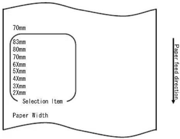
- Select "80mm" as your option.
Quickly press the FEED switch (up to one second) to move to "80mm".
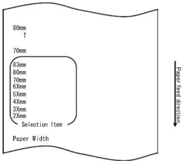
Press and hold down the FEED switch for at least one second to accept the selection.
The printer prints the following upon your acceptance of "80mm" selection:
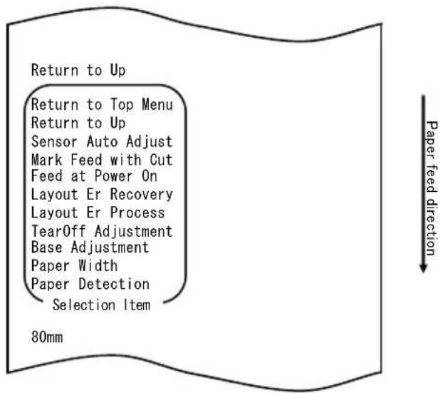
- Select "RETURN TO UP" as your option.
Press and hold down the FEED switch for at least one second to accept the selection.
The printer prints the following upon your acceptance of "RETURN TO UP" selection:
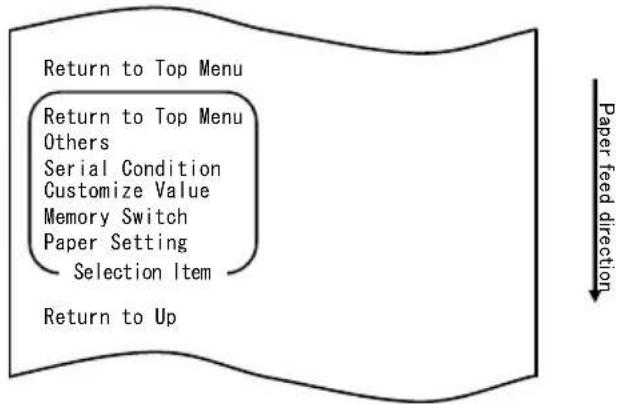
flowchart
graph TD
    A["Return to Top Menu"] --> B["Return to Top Menu"]
    B --> C["Others"]
    C --> D["Serial Condition"]
    D --> E["Customize Value"]
    E --> F["Memory Switch"]
    F --> G["Paper Setting"]
    G --> H["Selection Item"]
    H --> I["Return to Up"]
    style A fill:#f9f,stroke:#333
    style I fill:#ccf,stroke:#333
    note right of I: Paper feed direction
- Select "RETURN TO TOP MENU" as your option.
Press and hold down the FEED switch for at least one second to accept the selection.
The printer prints the following upon your acceptance of "RETURN TO TOP MENU" selection:
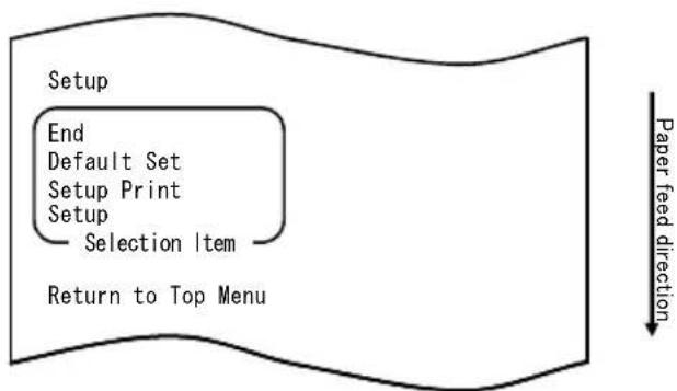
flowchart
graph TD
    A["Setup"] --> B["End"]
    B --> C["Default Set"]
    C --> D["Setup Print"]
    D --> E["Setup"]
    E --> F["Selection Item"]
    F --> G["Return to Top Menu"]
    H["Paper feed direction"] --> I["Arrow"]
- Select "END" as your option.
Quickly press the FEED switch three times (up to one second each) to move to "END".
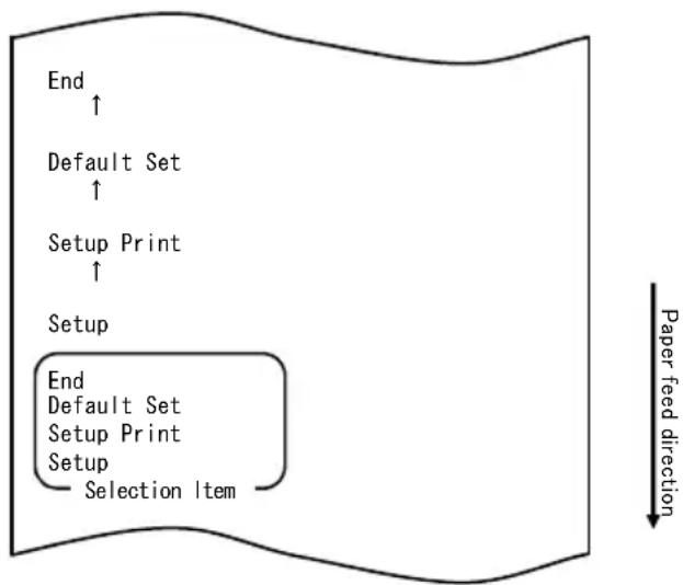
flowchart
graph TD
    A["End"] --> B["Default Set"]
    B --> C["Setup Print"]
    C --> D["Setup"]
    D --> E["End\nDefault Set\nSetup Print\nSetup\nSelection Item"]
    style A fill:#f9f,stroke:#333
    style B fill:#f9f,stroke:#333
    style C fill:#f9f,stroke:#333
    style D fill:#f9f,stroke:#333
    style E fill:#f9f,stroke:#333
    note right of E Paper feed direction
Then press and hold down the FEED switch for at least one second to accept the selection.
After you accept “END” selection, the printer cuts the paper and exits from setup mode.
Note: If you turn off the printer power switch without first selecting "END", your settings will be lost.
- Verifying your settings
To verify your settings, execute a test print as described in Section 10-1. The test printing prints a list of printer settings. Check the list to verify your settings.
Example (8) Changing the Batch(OTHER IF)
Change of the Batch(OTHER IF) value to ENABLE
The procedure for this setting change is as follows:
- Before starting work for this setting, verify the following printer conditions:
(1) The power is turned off.
(2) Paper is loaded on the printer.
(3) The cover is closed.
- Enter special mode.
Turn on the power switch on the right side of the printer while holding down the FEED switch on the left part of the top cover.
Note: You must hold down the FEED switch until the printer starts printing.
Note: If you have passed the item that you want to select, quickly press the FEED switch repeatedly until you return to the first item.
The printer prints the following when entering special mode:

flowchart
graph TD
    A["Test Print"] --> B["End"]
    B --> C["Sample Print"]
    C --> D["Data Analysis"]
    D --> E["Cleaning"]
    E --> F["Sensor Adjustment"]
    F --> G["Setup"]
    G --> H["Test Print"]
    H --> I["Selection Item"]
    J["Special Mode"] --> K["Usage"]
    L["Item Selection"] --> M["Please push the feed switch short."]
    N["Item Decision"] --> O["Please push the feed switch long."]
    P["Paper feed direction"] --> Q
- Enter setup mode from special mode.
Quickly press the FEED switch (up to one second) to move to "SETUP".

flowchart
graph TD
    A["Setup ↑"] --> B["Test Print"]
    B --> C["End\nSample Print\nData Analysis\nCleaning\nSensor Adjustment\nSetup\nTest Print\nSelection Item"]
    C --> D["Paper feed direction"]
Then press and hold down the FEED switch for at least one second to accept the selection.
The printer prints the following when entering setup mode:
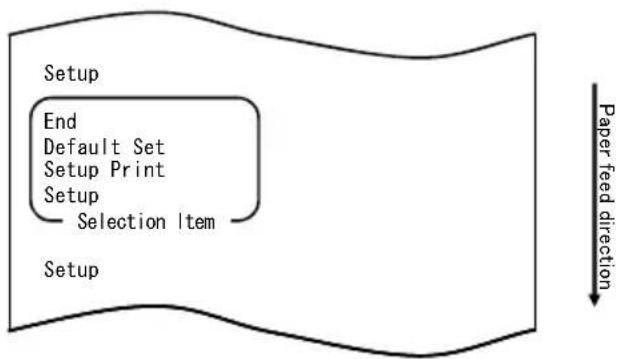
flowchart
graph TD
    A["Setup"] --> B["End"]
    B --> C["Default Set"]
    C --> D["Setup Print"]
    D --> E["Setup"]
    E --> F["Selection Item"]
    F --> G["Setup"]
    style A fill:#f9f,stroke:#333
    style G fill:#bbf,stroke:#333
    note right of G Paper feed direction
- In setup mode, select "SETUP".
Press and hold down the FEED switch for at least one second to accept the selection.

flowchart
graph TD
    A["Paper Setting"] --> B["Return to Top Menu"]
    B --> C["Others"]
    C --> D["Serial Condition"]
    D --> E["Customize Value"]
    E --> F["Memory Switch"]
    F --> G["Paper Setting"]
    G --> H["Selection Item"]
    I["Setup"] --> J["Paper feed direction"]
- Select "OTHERS" as your option.
Quickly press the FEED switch four times (up to one second each) to move to "OTHERS".
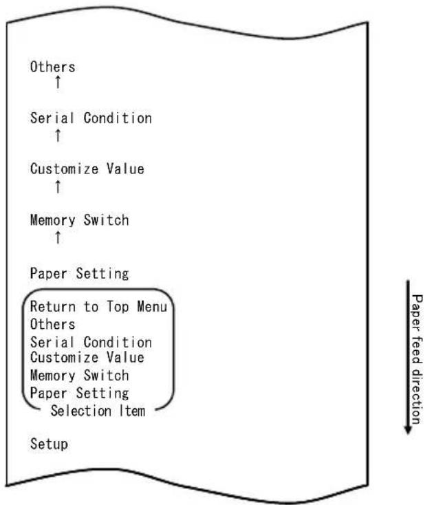
flowchart
graph TD
    A["Setup"] --> B["Paper Setting"]
    B --> C["Return to Top Menu"]
    B --> D["Others"]
    B --> E["Serial Condition"]
    B --> F["Customize Value"]
    B --> G["Memory Switch"]
    B --> H["Paper Setting"]
    B --> I["Selection Item"]
    B --> J["Customize Value"]
    B --> K["Customize Value"]
    B --> L["Customize Value"]
    B --> M["Customize Value"]
    B --> N["Customize Value"]
    B --> O["Customize Value"]
    B --> P["Customize Value"]
    B --> Q["Customize Value"]
    B --> R["Customize Value"]
    B --> S["Customize Value"]
    B --> T["Customize Value"]
    B --> U["Customize Value"]
    B --> V["Customize Value"]
    B --> W["Customize Value"]
    B --> X["Customize Value"]
    B --> Y["Customize Value"]
    B --> Z["Customize Value"]
    B --> AA["Customize Value"]
    B --> AB["Customize Value"]
    B --> AC["Customize Value"]
    B --> AD["Customize Value"]
    B --> AE["Customize Value"]
    B --> AF["Customize Value"]
    B --> AG["Customize Value"]
    B --> AH["Customize Value"]
    B --> AI["Customize Value"]
    B --> AJ["Customize Value"]
    B --> AK["Customize Value"]
    B --> AL["Customize Value"]
    B --> AM["Customize Value"]
    B --> AN["Customize Value"]
    B --> AO["Customize Value"]
    B --> AP["Customize Value"]
    B --> AQ["Customize Value"]
    B --> AR["Customize Value"]
    B --> AS["Customize Value"]
    B --> AT["Customize Value"]
    B --> AU["Customize Value"]
    B --> AV["Customize Value"]
    B --> AW["Customize Value"]
    B --> AX["Customize Value"]
    B --> AY["Customize Value"]
    B --> AZ["Customize Value"]
    B --> BA["Customize Value"]
    B --> BB["Customize Value"]
    B --> BC["Customize Value"]
    B --> BD["Customize Value"]
    B --> BE["Customize Value"]
    B --> BF["Customize Value"]
    B --> BG["Customize Value"]
    B --> BH["Customize Value"]
    B --> BI["Customize Value"]
    B --> BJ["Customize Value"]
    B --> BK["Customize Value"]
    B --> BL["Customize Value"]
    B --> BM["Customize Value"]
    B --> BN["Customize Value"]
    B --> BO["Customize Value"]
    B --> BP["Customize Value"]
    B --> BPB["Customize Value"]
    B --> BPAC["Customize Value"]
    B --> BPACB["Customize Value"]
    B --> BPACD["Customize Value"]
    B --> BPACE["Customize Value"]
    B --> BPACF["Customize Value"]
    B --> BPACG["Customize Value"]
    B --> BPACH["Customize Value"]
    B --> BPACI["Customize Value"]
    B --> BPACJ["Customize Value"]
    B --> BPACK["Customize Value"]
    B --> BPACL["Customize Value"]
    B --> BPACM["Customize Value"]
    B --> BPACN["Customize Value"]
    B --> BPACO["Customize Value"]
    B --> BPACP["Customize Value"]
    B --> BPACQ["Customize Value"]
    B --> BPACR["Customize Value"]
    B --> BPACS["Customize Value"]
    B --> BPACU["Customize Value"]
    B --> BPACU1["Customize Value"]
    B --> BPACUU["Customize Value"]
    B --> BPACUV["Customize Value"]
    B --> BPACUW["Customize Value"]
    B --> BPACUX["Customize Value"]
    B --> BPACUY["Customize Value"]
    B --> BPACUZ["Customize Value"]
    B --> BPACUZ1["Customize Value"]
    B --> BPACUU1["Customize Value"]
    B --> BPACUUU1["Customize Value"]
Then press and hold down the FEED switch for at least one second to accept the selection.
The printer prints the following upon your acceptance of "OTHERS" selection:
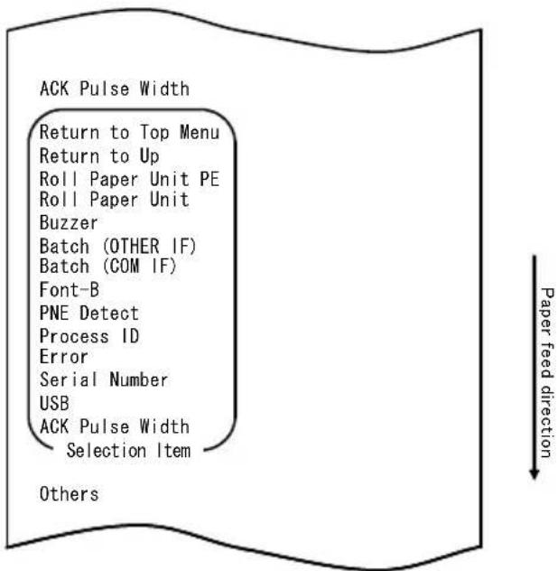
- Select "BATCH(OTHER IF)" as your option.
Quickly press the FEED switch eight times (up to one second each) to move to "BATCH(OTHER IF)".
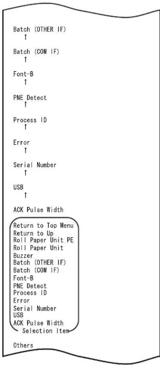
Paper feed direction
Press and hold down the FEED switch for at least one second to accept the selection.
The printer prints the following upon your acceptance of "BATCH(OTHER IF)" selection:
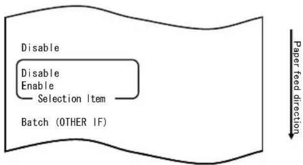
flowchart
graph TD
    A["Disable"] --> B["Enable"]
    B --> C["Selection Item"]
    C --> D["Batch (OTHER IF)"]
    style A fill:#f9f,stroke:#333
    style D fill:#ccf,stroke:#333
    note right of D Paper feed direction
7. Select "ENABLE" as your option.
Quickly press the FEED switch (up to one second) to move to "ENABLE".
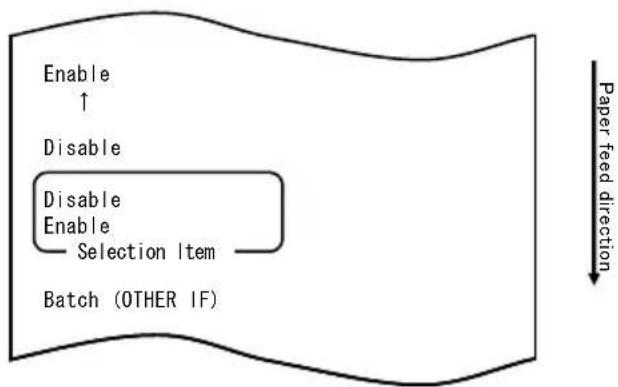
flowchart
graph TD
    A["Enable ↑"] --> B["Disable"]
    B --> C["Disable Enable Selection Item"]
    C --> D["Batch (OTHER IF)"]
    E["Paper feed direction"] --> F["-->"]
Press and hold down the FEED switch for at least one second to accept the selection.
The printer prints the following upon your acceptance of "ENABLE" selection:
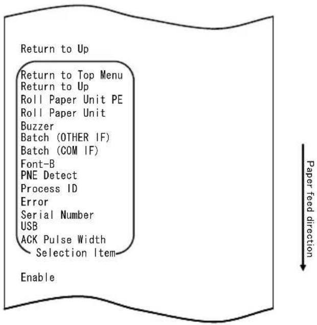
flowchart
graph TD
    A["Return to Up"] --> B["Return to Top Menu"]
    B --> C["Return to Up"]
    C --> D["Roll Paper Unit PE"]
    D --> E["Roll Paper Unit"]
    E --> F["Buzzer"]
    F --> G["Batch (OTHER IF)"]
    G --> H["Batch (COM IF)"]
    H --> I["Font-B"]
    I --> J["PNE Detect"]
    J --> K["Process ID"]
    K --> L["Error"]
    L --> M["Serial Number"]
    M --> N["USB"]
    N --> O["ACK Pulse Width"]
    O --> P["Selection Item"]
    P --> Q["Enable"]
- Select "RETURN TO UP" as your option.
Press and hold down the FEED switch for at least one second to accept the selection.
The printer prints the following upon your acceptance of "RETURN TO UP" selection:
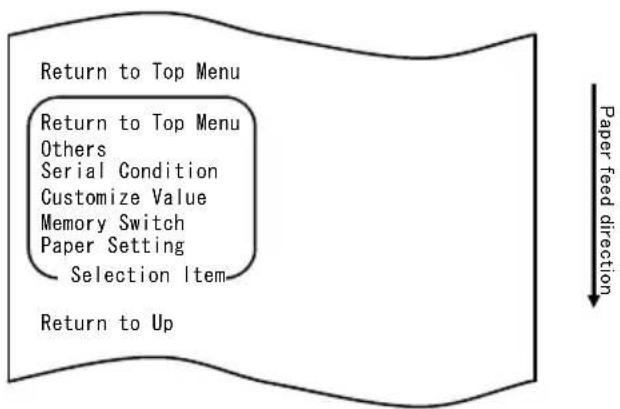
flowchart
graph TD
    A["Return to Top Menu"] --> B["Return to Top Menu"]
    B --> C["Others"]
    C --> D["Serial Condition"]
    D --> E["Customize Value"]
    E --> F["Memory Switch"]
    F --> G["Paper Setting"]
    G --> H["Selection Item"]
    H --> I["Return to Up"]
- Select "RETURN TO TOP MENU" as your option.
Press and hold down the FEED switch for at least one second to accept the selection.
The printer prints the following upon your acceptance of "RETURN TO TOP MENU" selection:
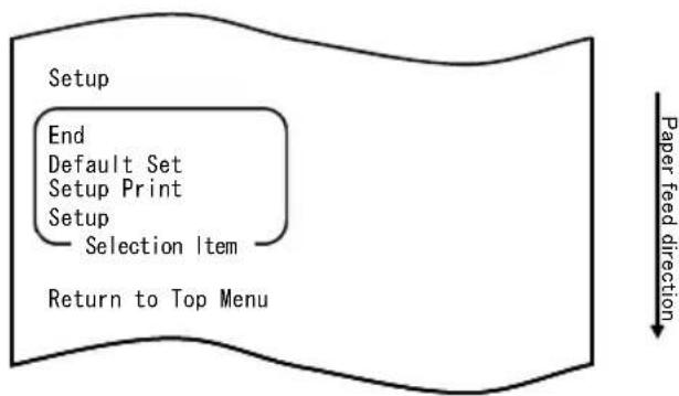
flowchart
graph TD
    A["Setup"] --> B["End"]
    B --> C["Default Set"]
    C --> D["Setup Print"]
    D --> E["Setup"]
    E --> F["Selection Item"]
    F --> G["Return to Top Menu"]
    H["Paper feed direction"] --> I["Downward arrow"]
- Select "END" as your option.
Quickly press the FEED switch three times (up to one second each) to move to "END".
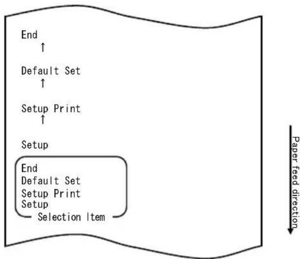
flowchart
graph TD
    A["End"] --> B["Default Set"]
    B --> C["Setup Print"]
    C --> D["Setup"]
    D --> E["End"]
    E --> F["Default Set"]
    F --> G["Setup Print"]
    G --> H["Setup"]
    H --> I["Selection Item"]
    style A fill:#f9f,stroke:#333
    style B fill:#f9f,stroke:#333
    style C fill:#f9f,stroke:#333
    style D fill:#f9f,stroke:#333
    style E fill:#f9f,stroke:#333
    style F fill:#f9f,stroke:#333
    style G fill:#f9f,stroke:#333
    style H fill:#f9f,stroke:#333
    style I fill:#f9f,stroke:#333
Then press and hold down the FEED switch for at least one second to accept the selection.
After you accept “END” selection, the printer cuts the paper and exits from setup mode.
Note: If you turn off the printer power switch without first selecting "END", your settings will be lost.
- Verifying your settings
To verify your settings, execute a test print as described in Section 10-1. The test printing prints a list of printer settings. Check the list to verify your settings.
10-3. Setup Items
Setup group items
| No | Setup group item Explanation | |
| 1 | Paper Setting Enters the mode for PAPER-related settings. | |
| 2 | Memory Switch Enters the mode for MEMORY SWITCH-related settings. | |
| 3 | Customize Value Enters the mode for CUSTOMIZE VALUE-related settings. | |
| 4 | Serial Condition Enters the mode for SERIAL INTERFACE CONDITION-related settings. | |
| 5 | Others Enters the mode for other types of settings. | |
| 6 | Return to Top Menu Returns to the setup mode menu. | |
Setup items and their details
(1) Paper Setting setup items
| No | Item Explanation Detailed setup item | ||
| 1 | Paper Detection Specifies the paper detection mode assumed used with automatic setting of the paper layout.- AUTO is the recommended item for use with multiple paper types. | AutoLabelBlack MarkNormal | |
| 2 | Paper Width | Specifies the paper width used. | |
| When "2x mm" is selected | |||
| When "3x mm" is selected | |||
| When "4x mm" is selected | |||
| When "5x mm" is selected | |||
| When "6x mm" is selected | |||
| No | Item Explanation Detailed setup item | ||
| 3 | Base Adjustment | Specifies the value used for batch correction of the start position, cutting position, peeling-off position and tear-off position. | -5.0 mm-4.X mm-3.X mm-2.X mm-1.X mm-0.X mm0.0 mm+0.X mm+1.X mm+2.X mm+3.X mm+4.X mm+5.0 mm |
| When "-4.X mm" is selected -4.0 to -4.9 mm | |||
| When "-3.X mm" is selected -3.0 to -3.9 mm | |||
| When "-2.X mm" is selected -2.0 to -2.9 mm | |||
| When "-1.X mm" is selected -1.0 to -1.9 mm | |||
| When "-0.X mm" is selected -0.0 to -0.9 mm | |||
| When "+0.X mm" is selected +0.0 to +0.9 mm | |||
| When "+1.X mm" is selected +1.0 to +1.9 mm | |||
| When "+2.X mm" is selected +2.0 to +2.9 mm | |||
| When "+3.X mm" is selected +3.0 to +3.9 mm | |||
| When "+4.X mm" is selected +4.0 to +4.9 mm | |||
| 4 | TearOff Adjustment | Specifies the value used for correction of the tear-off position. | -5.0 mm-4.X mm-3.X mm-2.X mm-1.X mm-0.X mm0.0 mm+0.X mm+1.X mm+2.X mm+3.X mm+4.X mm+5.0 mm |
| When "-4.X mm" is selected -4.0 to -4.9 mm | |||
| When "-3.X mm" is selected -3.0 to -3.9 mm | |||
| When "-2.X mm" is selected -2.0 to -2.9 mm | |||
| When "-1.X mm" is selected -1.0 to -1.9 mm | |||
| When "-0.X mm" is selected -0.0 to -0.9 mm | |||
| When "+0.X mm" is selected +0.0 to +0.9 mm | |||
| When "+1.X mm" is selected +1.0 to +1.9 mm | |||
| When "+2.X mm" is selected +2.0 to +2.9 mm | |||
| When "+3.X mm" is selected +3.0 to +3.9 mm | |||
| When "+4.X mm" is selected +4.0 to +4.9 mm | |||
| No | Item Explanation Detailed setup item | |
| 5 | Layout Er Process Specifies the action to be taken if a paper layout error occurs.- Specify whether to clear the paper layout error information stored in memory.- To continue using the same paper, do not clear the paper layout information.- To use a different type of paper, clear the paper layout information. | Layout Continue Layout Clear |
| 6 | Layout Er Recovery Specifies the condition for recovery from a paper layout error.- Command transmission may be impossible, such as because the receive buffer is in the full state, if a paper layout error occurs. In this case, use Command/Cover Close instead of Command. | Command/CoverClose Command |
| 7 | Feed at Power On Specifies whether to feed paper to the start position at power-on.- If Disable is specified and the head is not positioned at the start position at power-on, a print misalignment or paper layout error may result. | Enable Disable |
| 8 | Mark Feed with Cut Specifies whether to cut paper after feeding paper to the start position.- If Enable is specified, the printer cuts the paper that has been advanced to the start position as triggered by a power-on, a reset, the closing of the cover, or the pressing of the FEED switch. The printer does not cut the paper that is fed to the start position by a command. | Enable Disable |
| 9 | Sensor Auto Adjust Specifies whether to automatically adjust the label and black mark sensors when automatic setting of the paper layout is enabled. | Enable Disable |
| 10 | Return to Up Returns to the selection mode for the setup group items. | - |
| 11 | Return to Top Menu Returns to the setup mode menu. |
(2) Memory Switch setup items
| No | Item Explanation Detailed setup item | ||
| 1 | Power On Status - Specifies reporting the power-on state. | Enable Disable | |
| 2 | Receive Buffer - Specifies the capacity of the receive buffer. | 45Byte 4KByte | |
| 3 | Busy Condition - Specifies the printer BUSY condition. | Bufferfull Offline/Bufferfull | |
| 4 | Receive Error | - Specifies how to handle receive errors- This item is valid only for the serial interface. | Ignore ?Print |
| 5 | Auto LF - Specifies automatic line feed using the CR code.- This item is valid only for the Parallel interface. | Enable Disable | |
| 6 | DSR(#6) Reset - Specifies the reset operation using the DSR (#6) signal.- This item is valid only for the serial interface. | Enable Disable | |
| 7 | INIT(#25) Reset | - Specifies the reset operation using the INIT (#25) signal.- This item is valid only for the serial interface. | Enable Disable |
| 8 | INIT(#31) Reset | - Specifies reset using the INIT#able signal.- This item is valid only for the parallel interface. | Enable Disable |
| 9 | Cover Open Error | - Specifies how to handle a cover open error during printing. | Auto Recovery Recovery by CMND |
| 10 | Return to Up | - Returns the menu to the selection mode for setup group items. | - |
| 11 | Return to Top Menu | - Returns the menu to the setup mode menu. | - |
(3) Customize Value setup items
| No | Item | Explanation | Detailed setup item | |
| 1 | User NV Memory - Capacity of the user NV memory. 1KBYTE | 64KBYTE,128KBYTE192KBYTE | ||
| 2 | NV Graphic Memory - Capacity of the NV graphic memory. | None64KByte128KByte192KByte256KByte320KByte384KByte | ||
| 3 | Print Color - Print colors. | Mono2 Color | ||
| 4 | Print Density | - Print density. | 70%(Lightest)75%80%85%90%95%100%105%110%115%120%125%130%(Darkest) | |
| 5 | BK Density | - Black density when "2 Color" is set for Print Color. | 70%(Lightest)75%80%85%90%95%100%105%110%115%120%125%130%(Darkest) | |
| No | Item Explanation Detailed setup item | ||
| 6 | Max Speed - Maximum | print speed.1:60mm/S 2:80mm/S3:100mm/S 4:120mm/S5:140mm/S 6:160mm/S7:180mm/S 8:220mm/S9:260mm/S | 1st(Low Speed)2nd3rd4th5th6th7th8th9th(High Speed) |
| 7 | Low Power | Print speed(maximum)Mode1: Printing at 80% of the specified print densityMode2: Varying of the strobe pulse width | NormalMode1:Reduction of about 10%Mode2:Reduction of about 30% |
| 8 | Return to Up - Returns | to the selection mode for the setup group items. | - |
| 9 | Return to Top Menu - Returns | to the selection mode for the setup group items. | |
(4) Serial Condition setup items
| No | Item Explanation Detailed setup item | |||
| 1 | Baudrate - Baud rate. 2400BPS | 4800BPS9600BPS19200BPS38400BPS57600BPS115200BPS | ||
| 2 | Format - Data format. 7EVEN1 | 7ODD18NONE18EVEN18ODD1 | ||
| 3 | Protocol - Buffer control protocol. XON/XOFF | DSR/DTR | ||
| 4 | Return to Up - Returns to the selection mode for the setup group items. | - | ||
| 5 | Return to Top Menu | - Returns to the setup mode. | - | |
(5) Others setup items
| No | Item Explanation | Detailed setup item | |
| 1 | ACK Pulse Width | - Specifies the ACK pulse width. | 1μs8μs |
| 2 | USB - Specifies the use of the USB connection. | - Specifies the type of Serial Number notification in a USB connection. Generally, specify "ENABLE." | V-COM Printer |
| 3 | Serial Number | Enable Disable | |
| 4 | Error | - Specifies the mode for the power-on time and the error recovery time. Auto Recovery:Windows drivers are used. Recovery by CMND:OPOS drivers are used. | Auto Recovery Recovery by CMND |
| 5 | Process ID | - Specifies a process ID. Normal:Responds with the process ID at the end of printing. High Speed:Responds with the process ID at the end of data reception. | Normal High Speed |
| 6 | PNE Detect | - Specifies whether to report the paper-near-end condition. | Enable Disable |
| No | Item | Explanation | Detailed setup item |
| 7 | Font-B | - Specifies Font B. Mode1: Font in the standard specifications Mode2: compatible font | Mode1 Mode2 |
| 8 | Bstch(COM IF) | - Batch printing: Received data is printed in a batch. (Priority is placed on print quality.) - Serial printing: Received data is printed serially. (Priority is placed on print speed.) * This item is valid only with the serial interface. | Enable Disable |
| 9 | Batch(OTHER IF) | - Batch printing: Received data is printed in a batch. (Priority is placed on print quality.) - Serial printing: Received data is printed serially. (Priority is placed on print speed.) * This item is valid with the USB, Parallel or LAN interface. | Enable Disable |
| 10 | Buzzer | - Specifies whether to sound the buzzer at error occurrence. The buzzer can be sounded by a command even if "Disable" is specified. (This item is valid only for a device specified to have a buzzer installed.) | Enable Disable |
| 11 | Roll Paper Uuit | Specifies whether the roll paper unit (option) is installed. | Uninstall Installed |
| 12 | Roll Paper Unit PE | - Specifies the sensor to be used to sense "no paper" status when the large-diameter roll unit is installed. - PE: The unit is judged in paper end status if the paper end sensor senses "no paper" status. - PNE: The unit is judged in paper end status if the paper-near-end sensor senses "no paper" status. * This item is valid only for plain paper (including full-sheet label paper). | PE PNE |
| 13 | Return to Up - Returns to the selection mode for the setup group items. | - | |
| 14 | Return to Top Menu - Returns to the setup mode menu. | ||
10-4. Sensor Adjustment
10-4-1. Sensor adjustment mode
- Before starting work for this adjustment, verify the following printer conditions:
(1) The power is turned off.
(2) Paper is loaded on the printer.
(3) The cover is closed.
- Enter special mode.
Turn on the power switch on the right side of the printer while holding down the FEED switch on the left part of the top cover.
Note: You must hold down the FEED switch until the printer starts printing.
Note: If you have passed the item that you want to select, quickly press the FEED switch repeatedly until you return to the first item.
The printer prints the following when entering special mode:
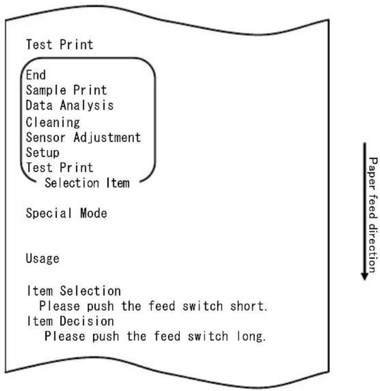
flowchart
graph TD
    A["Test Print"] --> B["End"]
    B --> C["Sample Print"]
    C --> D["Data Analysis"]
    D --> E["Cleaning"]
    E --> F["Sensor Adjustment"]
    F --> G["Setup"]
    G --> H["Test Print"]
    H --> I["Selection Item"]
    J["Special Mode"] --> K["Usage"]
    L["Item Selection"] --> M["Please push the feed switch short."]
    N["Item Decision"] --> O["Please push the feed switch long."]
    P["Paper feed direction"] --> Q
1) Quickly press the FEED switch twice (up to one second each). When <
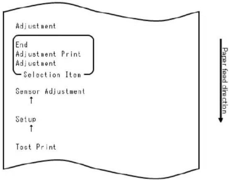
flowchart
graph TD
    A["Adjustment"] --> B["End"]
    B --> C["Adjustment Print"]
    C --> D["Adjustment"]
    D --> E["Selection Item"]
    E --> F["Sensor Adjustment"]
    F --> G["Setup"]
    G --> H["Test Print"]
    style A fill:#f9f,stroke:#333
    style F fill:#ccf,stroke:#333
    style G fill:#cfc,stroke:#333
    style H fill:#fcc,stroke:#333
■ How to select an item
1) Each time that you press the FEED switch briefly and release it, the printer operates as follows:
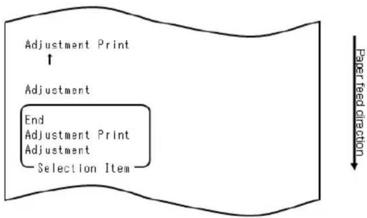
flowchart
graph TD
    A["Adjustment Print"] --> B["End Adjustment Print Adjustment Selection Item"]
    C["Adjustment"] --> A
    D["Paper feed direction"] --> E["Downward arrow"]
2) The printer prints "ADJUSTMENT", "ADJUSTMENT PRINT", "END", "ADJUSTMENT," and so on cyclically in this order.
■ How the printer accepts your selection of an item
1) When you press and hold down the FEED switch for one second or longer, the printer accepts the top printed item as your option.
2) Then, the printer starts processing for the selected item.
■ END
1) When "END" is printed, press and hold down the FEED switch for one second or longer to end sensor adjustment.
2) The printer returns to normal operation mode.
■ ADJUSTMENT
1) When "ADJUSTMENT PRINT" is printed, press and hold down the FEED switch
for one second or longer to start printing of settings.
2) The printer prints all the current settings.
3) After printing the settings, the printer returns to its state at the start of sensor adjustment.
ADJUSTMENT
1) When "ADJUSTMENT" is printed, press and hold down the FEED switch for one second or longer to start sensor adjustment. a. The printer prints the selection items.
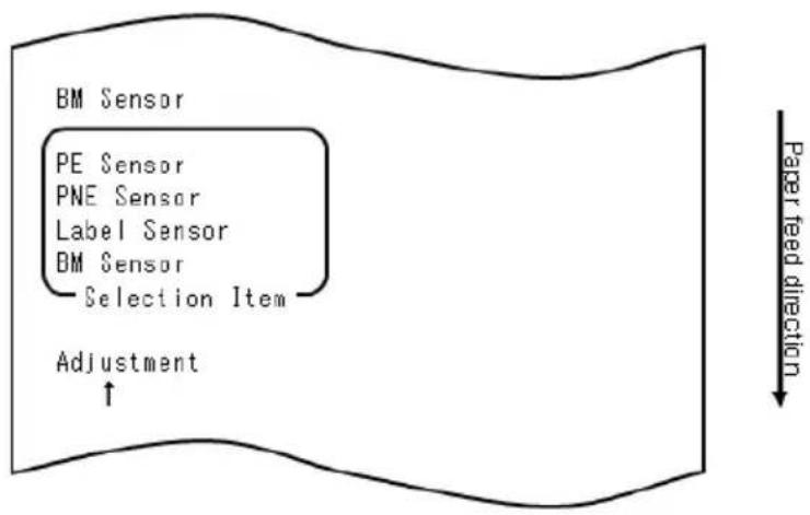
flowchart
graph TD
    A["BM Sensor"] --> B["PE Sensor"]
    B --> C["PNE Sensor"]
    C --> D["Label Sensor"]
    D --> E["BM Sensor"]
    E --> F["Selection Item"]
    F --> G["Adjustment"]
    G --> H["↑"]
    style A fill:#f9f,stroke:#333
    style H fill:#ccf,stroke:#333
    note right of H "Paper feed direction"
2) The printer prints "BM SENSOR," "LABEL SENSOR," "PNE SENSOR," "PE SENSOR," "BM SENSOR," and so on cyclically in this order.
10-4-2. Black mark (BM) sensor adjustment
1) When "BM SENSOR" is printed, press and hold down the FEED switch for one second or longer to start BM sensor adjustment.
2) The printer prints the following and then cuts the paper when BM sensor adjustment begins:
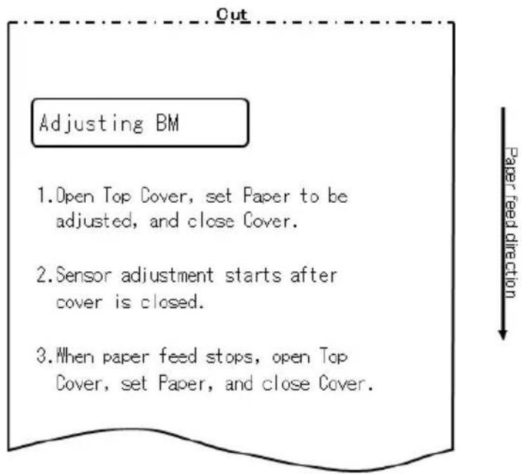
3) Open the top cover and load the paper you want to adjust. When you close the top cover, the printer starts feeding paper.
4) The printer stops the adjustment in the following cases:
a. The cover is opened.
b. The printer has no paper.
c. The adjustment is completed.
5) After paper feeding stops, load the original paper again. The printer prints the adjustment result.
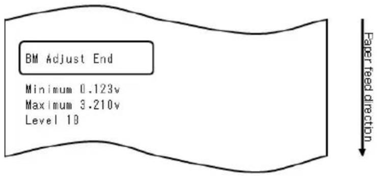
6) The printer writes the adjustment result in memory, and then returns to the previous state when sensor adjustment began.
7) If the adjustment failed, the printer prints "ADJUSTMENT FAILED" and then returns to its state at the start of sensor adjustment.
10-4-3. Adjusting the label sensor
1) When "LABEL SENSOR" is printed, press and hold down the FEED switch for one second or longer to start label sensor adjustment.
2) The printer prints the following and then cuts the paper when label sensor adjustment begins:
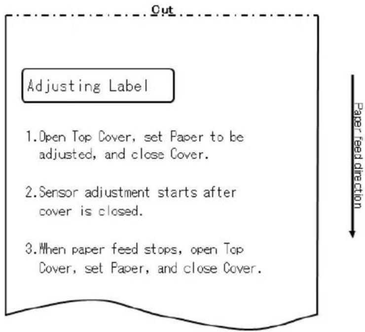
3) Open the top cover and load the paper you want to adjust. When you close the top cover, the printer starts feeding paper.
Note: Using any paper not meeting the requirements specified in Section 3-4-3, "Requirements for die-cut label paper," will result in an adjustment error.
4) The printer stops the adjustment in the following cases:
a. The cover is opened.
b. The printer has no paper.
c. The adjustment is completed.
5) After paper feeding stops, load the original paper again. The printer prints the adjustment result.
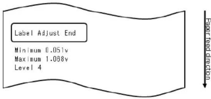
6) The printer writes the adjustment result in memory, and then returns to the previous state when sensor adjustment began.
7) If the adjustment failed, the printer prints "ADJUSTMENT FAILED" and then returns to its state at the start of sensor adjustment.
10-4-4. Paper-near-end (PNE) sensor adjustment
1) When "PNE SENSOR" is printed, press and hold down the FEED switch for one second or longer to start PNE sensor adjustment.
2) The printer prints the following and then cuts the paper when PNE sensor adjustment begins:
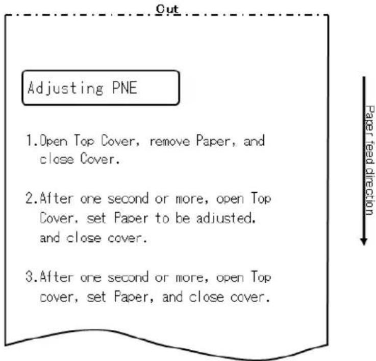
3) Open the top cover and load the paper you want to adjust. When you close the top cover, the printer starts feeding paper.
4) The printer stops the adjustment in the following case: a. The adjustment is completed.
5) After the adjustment ends, load the original paper again. The printer prints the adjustment result.
6) The printer writes the adjustment result in flash memory and then returns to its state at the start of sensor adjustment.
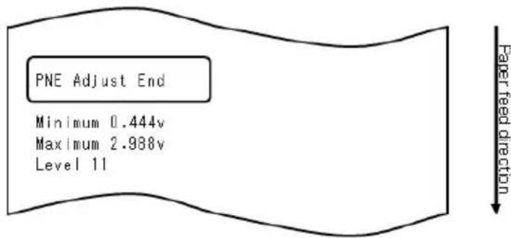
7) The printer writes the adjustment result in memory, and then returns to the previous state when sensor adjustment began.
10-4-5. Paper end (PE) sensor adjustment
Note: You need not adjust the PE sensor when using plain paper (including full-sheet label paper) or black mark paper.
1) When "PE SENSOR" is printed, press and hold down the FEED switch for one second or longer to start PE sensor adjustment.
2) The printer prints the following and then cuts the paper when PE sensor adjustment begins:
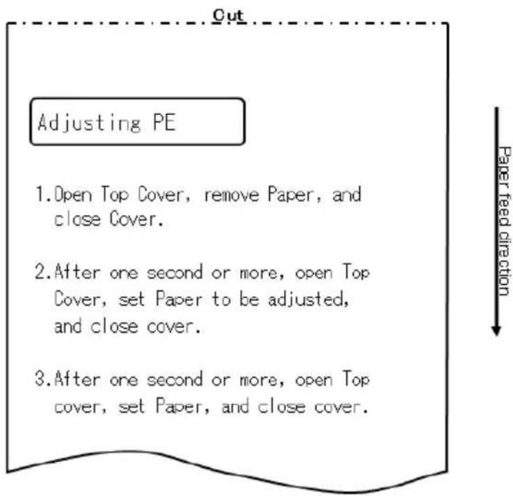
3) Open the top cover and load the paper you want to adjust. When you close the top cover, the printer starts feeding paper.
Note: When loading die-cut label paper, partially peel off the label from the base paper with the label-peeled portion facing the label sensor, and then close the cover.
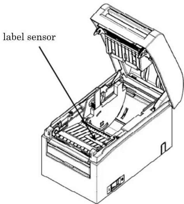
5) The printer stops the adjustment in the following case: a. The adjustment is completed.
6) After the adjustment ends, load the original paper again. The printer prints the adjustment result.

7) The printer writes the adjustment result in memory, and then returns to the previous state when sensor adjustment began.
8) If the adjustment failed, the printer prints "ADJUSTMENT FAILED" and then returns to its state at the start of sensor adjustment.
10-5. Data Analysis
With paper inserted in the printer, turn off the printer power switch once. If you turn on the switch again while holding down the FEED switch on the control panel, the data shown in Section 10-1 will be printed. If you turn on the switch again and press the FEED switch briefly, the data shown below will be printed.
The printer prints the following when it enters the special mode:

flowchart
graph TD
    A["Test Print"] --> B["End Sample Print"]
    B --> C["Data Analysis"]
    C --> D["Cleaning"]
    D --> E["Sensor Adjustment"]
    E --> F["Setup"]
    F --> G["Test Print"]
    G --> H["Selection Item"]
    I["Special Mode"] --> J["Usage"]
    J --> K["Item Selection"]
    K --> L["Please push the feed switch short."]
    K --> M["Item Decision"]
    M --> N["Please push the feed switch long."]
    O["Paper feed direction"] --> P
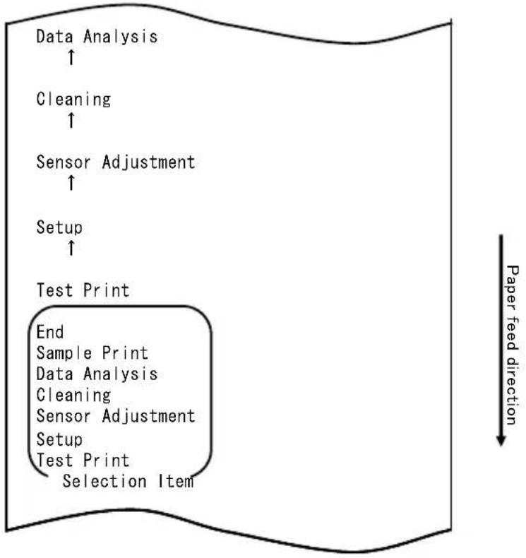
flowchart
graph TD
    A["Data Analysis ↑"] --> B["Cleaning ↑"]
    B --> C["Sensor Adjustment ↑"]
    C --> D["Setup ↑"]
    D --> E["Test Print"]
    E --> F["End Sample Print Data Analysis Cleaning Sensor Adjustment Setup Test Print Selection Item"]
    style E fill:#f9f,stroke:#333
    note right of E Paper feed direction
The printer enters received data analysis mode from the special mode. Press the FEED switch briefly (one second or less) four times to move to "DATA ANALYSIS".
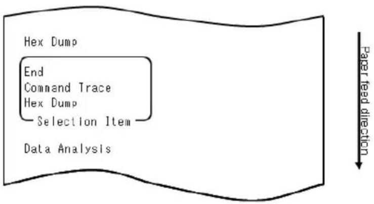
flowchart
graph TD
    A["Hex Dump"] --> B["End"]
    B --> C["Command Trace"]
    C --> D["Hex Dump"]
    D --> E["Selection Item"]
    E --> F["Data Analysis"]
    G["Paper feed direction"] --> H["Downward arrow"]
1. HEX DUMP mode
Then, press and hold down the FEED switch for one second or longer to accept the selection.
When "HEX DUMP" is printed, press and hold down the FEED switch for one second or longer to place the printer in hex dump mode.
In hex dump mode, all signals sent from the host computer to the printer are printed as hexadecimal codes. The printed data can be used to confirm that the correct control codes have been sent to the printer by a created program.
To reset this mode, turn off the power switch once.
Sample hex dump test printout
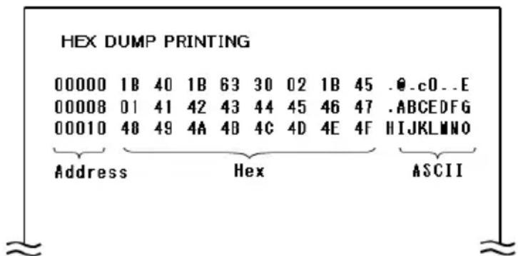
2. Command trace mode
Quickly press the FEED switch (up to one second), and then press and hold down the FEED switch for at least one second to accept the selection.
In command trace mode, all data sent from the host computer to the printer is printed as command names. The printed data can be used to confirm that correct control codes have been sent to the printer by a created program.
To reset this mode, turn off the power switch once.
Example of command trace output
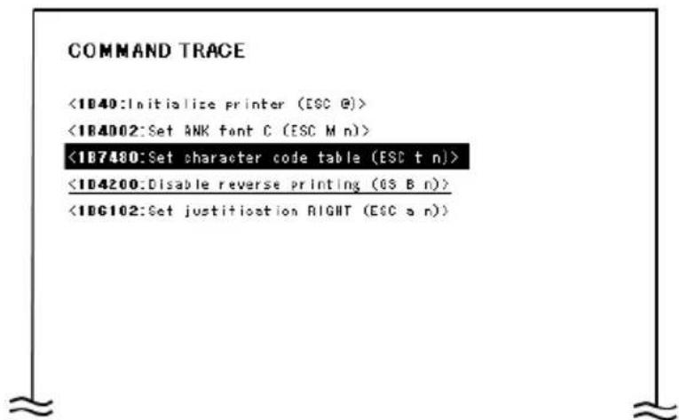
10-6. Sample Print
With paper inserted in the printer, turn off the printer power switch once. If you turn on the switch again while holding down the FEED switch on the control panel, the data shown in Section 10-1 will be printed. If you turn on the switch again and press the FEED switch briefly, the data shown below will be printed.
The printer prints the following when it enters the special mode:
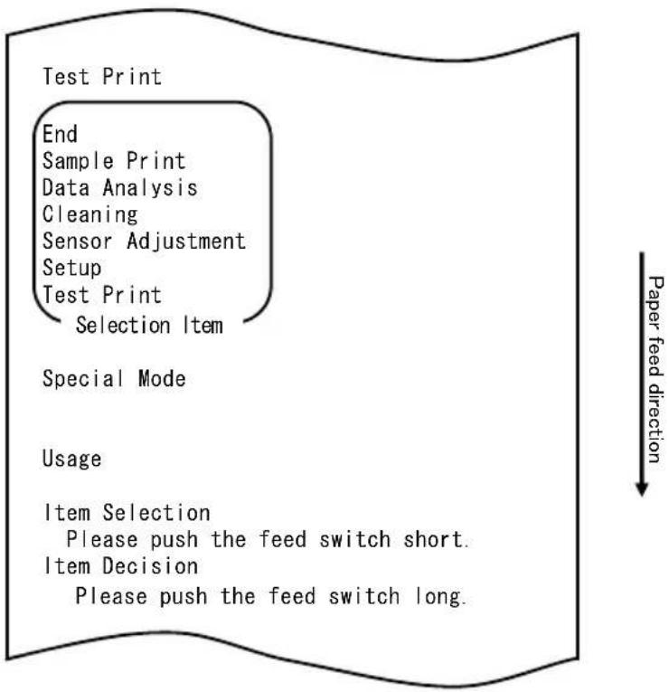
flowchart
graph TD
    A["Test Print"] --> B["End"]
    B --> C["Sample Print"]
    C --> D["Data Analysis"]
    D --> E["Cleaning"]
    E --> F["Sensor Adjustment"]
    F --> G["Setup"]
    G --> H["Test Print"]
    H --> I["Selection Item"]
    I --> J["Special Mode"]
    J --> K["Usage"]
    K --> L["Item Selection"]
    L --> M["Please push the feed switch short."]
    L --> N["Item Decision"]
    N --> O["Please push the feed switch long."]
    P["Paper feed direction"] --> Q

flowchart
graph TD
    A["Sample Print ↑"] --> B["Data Analysis ↑"]
    B --> C["Cleaning ↑"]
    C --> D["Sensor Adjustment ↑"]
    D --> E["Setup ↑"]
    E --> F["Test Print"]
    F --> G["End Sample Print"]
    G --> H["Data Analysis Cleaning"]
    H --> I["Sensor Adjustment Setup"]
    I --> J["Test Print Selection Item"]
    style F fill:#f9f,stroke:#333
    note right of F Paper feed direction
The printer enters sample print mode from the special mode.
Press the FEED switch briefly (one second or less) five times to move to "SAMPLE PRINT".
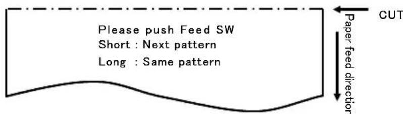
The printed pattern is as follows.
a) LABEL1 pattern
b) LABEL2 pattern
c) LABEL3 pattern
d) LABEL4 pattern
e) LABEL5 pattern
When the FEED switch is pressed short, the following pattern is printed.
“LABEL1”→“LABEL2”→“LABEL3”→“LABEL4”→“LABEL5”
When the FEED switch is pressed long (about one second), the same pattern is printed again.
The sample print mode is ended by the printer power supply determination.
Printed result of sample printings
"LABEL1" pattern
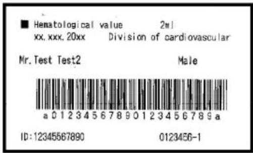
"LABEL2" pattern
| name | Pizza |
| ingredient | Wheat, Yeast, Olives, Olive oil, Tomato, Mozzarella cheese, Basil Oregano, Onions, Capers, Sausage, Chile Peppers, Mushrooms Anchovies |
| Expiration | XX-XX-20xx |
| Manufacturer | OK! Food Ltd. |
"LABEL3" pattern
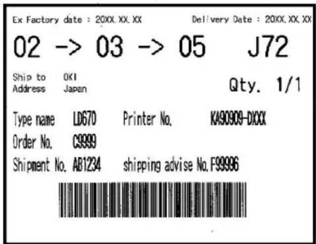
"LABEL4" pattern

"LABEL5" pattern
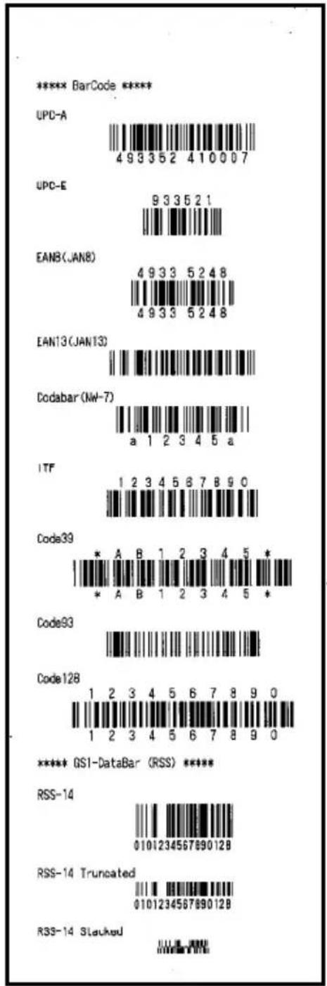
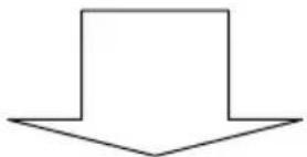
natural_image
Simple downward-pointing arrow shape with no text or symbols
natural_image
Simple downward-pointing arrow shape with no text or symbols11. Regular Cleaning
Printed characters may not be completely formed if paper residue, dust, or a similar material is present. To ensure proper printing, remove any paper residue and dust on the paper holder, paper transport components, platen roller, and surface of the thermal head. Cleaning is required monthly.
In particular, if the printer uses full-sheet label paper in full cutting mode, any adhesive matter adhering to the paper ejecting part of the paper guide may cause a paper ejection error. Using an alcohol solvent, remove adhesive matter periodically from the paper guide.
- Recommended cleaning cycle: For a minimum cutting interval of 15 mm, clean the paper guide each time that printing on one or two rolls (about 5000 cuts) is completed.
Note: Do not use a solvent other than ethyl or isopropyl alcohol.
11-1. Cleaning the Paper Holder and Paper Transport
With a dry soft cloth, wipe the paper holder and paper transport to remove dust, paper particles, adhesive, and other foreign matter.
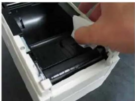
natural_image
Hand inserting a plastic component into a white plastic housing (no text or symbols visible)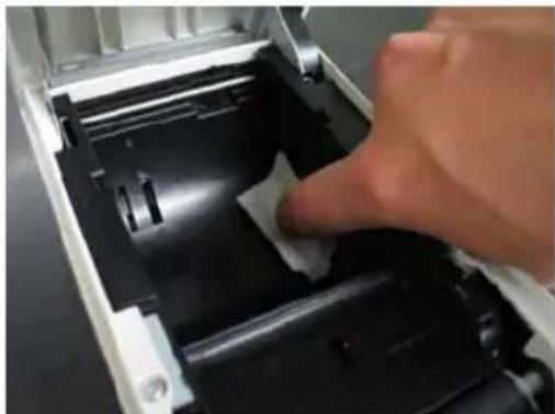
natural_image
Close-up of a hand pressing down on a mechanical component, showing internal structure and part (no text or symbols visible)11-2. Cleaning the Platen Roller
The cleaning procedure is as follows.
(1) With paper inserted in the printer, turn off the printer power switch once, and turn on the switch again while holding down the FEED switch on the control panel. Then, the data shown below is printed.
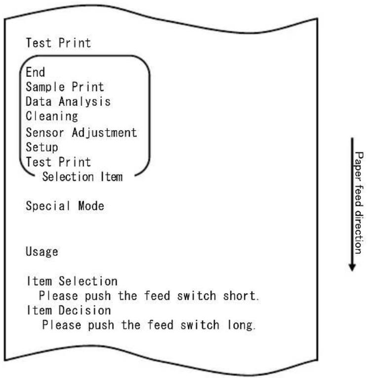
flowchart
graph TD
    A["Test Print"] --> B["End"]
    B --> C["Sample Print"]
    C --> D["Data Analysis"]
    D --> E["Cleaning"]
    E --> F["Sensor Adjustment"]
    F --> G["Setup"]
    G --> H["Test Print"]
    H --> I["Selection Item"]
    J["Special Mode"] --> K["Usage"]
    L["Item Selection"] --> M["Please push the feed switch short."]
    N["Item Decision"] --> O["Please push the feed switch long."]
    P["Paper feed direction"] --> Q
(2) Select "CLEANING" as your option.
Press the FEED switch briefly (one second or less) three times to move to "CLEANING."
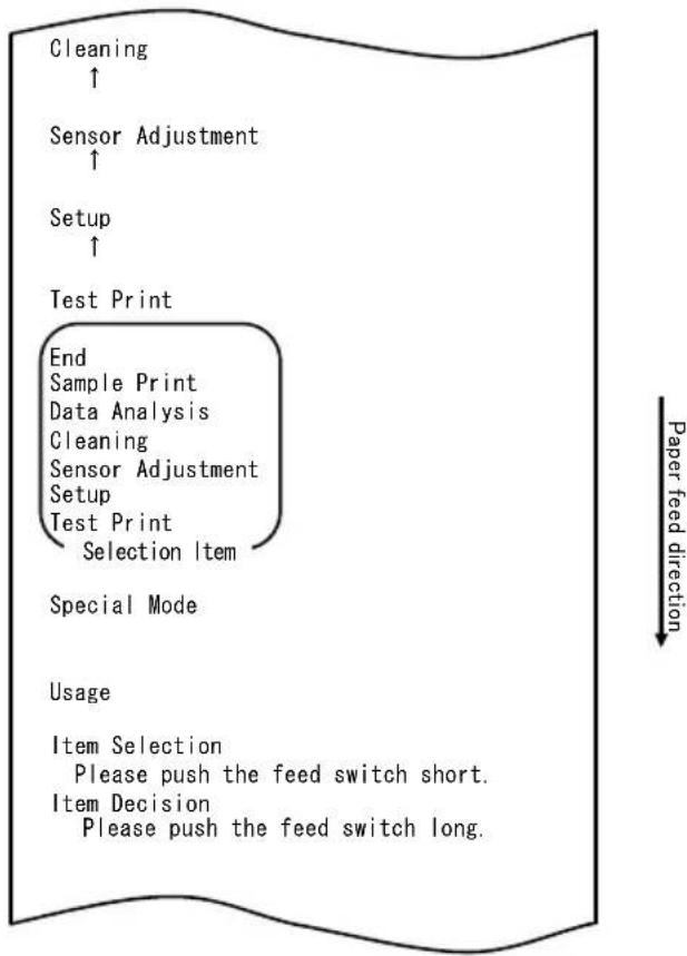
flowchart
graph TD
    A["Cleaning ↑"] --> B["Sensor Adjustment ↑"]
    B --> C["Setup ↑"]
    C --> D["Test Print"]
    D --> E["End Sample Print Data Analysis Cleaning Sensor Adjustment Setup Test Print Selection Item"]
    E --> F["Special Mode"]
    F --> G["Usage"]
    G --> H["Item Selection Please push the feed switch short. Item Decision Please push the feed switch long."]
(3) Press and hold down the FEED switch for one second or longer to accept the selection.
The printer prints the following when you accept the selection of "CLEANING":

flowchart
graph TD
    A["Platen Cleaning"] --> B["End"]
    B --> C["Cutter Cleaning"]
    C --> D["Platen Cleaning"]
    D --> E["Selection Item"]
    E --> F["Cleaning"]
    F --> G["↑"]
    style A fill:#f9f,stroke:#333
    style G fill:#ccf,stroke:#333
Then, press and hold down the FEED switch for one second or longer to accept the selection. The printer enters platen roller cleaning mode. The printer prints the following and cuts the paper when it enters platen roller cleaning mode:
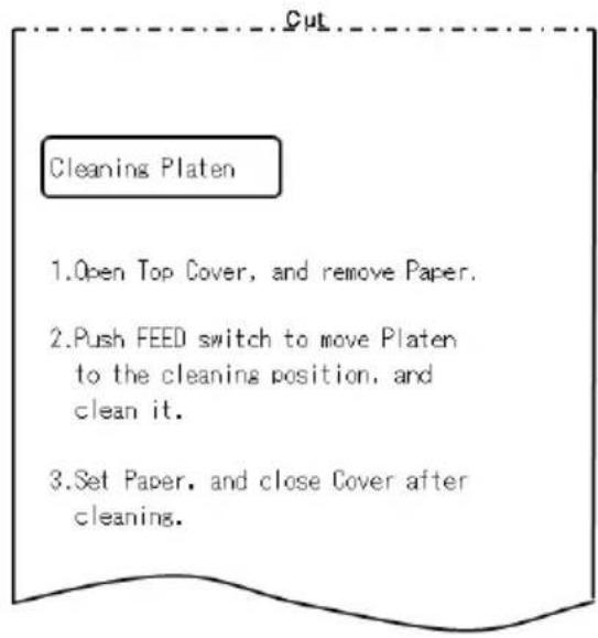
(4) Open the top cover, and remove the roll paper.
(5) Press the FEED switch to rotate the platen roller to a position that will facilitate cleaning, and then wipe the platen roller with a dry soft cloth to remove paper particles, adhesive, and other foreign matter from the surface of the platen roller.
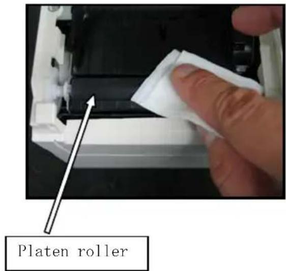
(6) After completing cleaning, reposition the roll paper, and close the top cover.
Note : Take care not to dent or otherwise damage the platen roller.
A dent on the platen roller may result in incomplete printing or line feed errors.
Note : Each time that the FEED switch is pressed, the platen roller is rotated by 1/12 of a turn.
11-3. Cleaning the Thermal Head
(1) Before attempting to clean the thermal head, be sure to turn off the printer power switch.
(2) Open the top cover.
(3) Using an alcohol solvent, remove black paper particles and other residue from the surface of the thermal head. If the printer printed on label paper, any adhesive matter adhering to the surface of the thermal head must be removed.
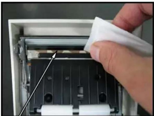
natural_image
Close-up of a hand inserting a white plastic bag into a black industrial machine casing with rollers (no text or symbols visible)Thermal head
Note : The thermal head is susceptible to damage. When cleaning it, use a soft cloth and be especially careful not to damage the head.
Note : Immediately after printing, the thermal head is hot. Wait about 10 minutes before cleaning the head.
Note : Because the thermal head is susceptible to damage by static electricity, take precautions to prevent the generation of static electricity.
Note : Do not turn on the printer until all alcohol has dried.
Note: Do not use a solvent other than ethyl or isopropyl alcohol.
11-4. Cleaning the Cutter Blade and Frame
If the printer printed on full-sheet label paper, any adhesive matter adhering to the cutter blade and frame must be removed.
Even when label paper has been cut normally, clean the cutter blade at an interval of about once a month to ensure stability in cutting.
Note: Although the edge of the cutter blade is not as sharp as the edges of utility knives generally used in offices, there is a risk of injury to a hand or finger that is moved while pressed against the cutter blade edge. Take care to avoid injury when cleaning the cutter blade.
Items required for cleaning
- Flathead screwdriver (small) Cleaning sheet
- General-purpose utility knife (Product No.: 0631260)
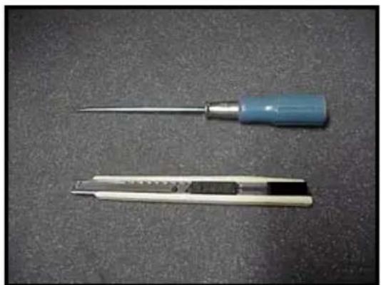
natural_image
Two types of screwdriver tools on a dark surface, one with a metallic tip and the other with a flat blade (no text or symbols visible)
The cleaning procedure is as follows.
(1) With paper inserted in the printer, turn off the printer power switch once, and turn on the switch again while holding down the FEED switch on the control panel. Then, the data shown below is printed.
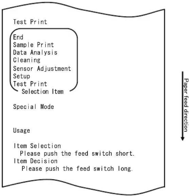
flowchart
graph TD
    A["Test Print"] --> B["End"]
    B --> C["Sample Print"]
    C --> D["Data Analysis"]
    D --> E["Cleaning"]
    E --> F["Sensor Adjustment"]
    F --> G["Setup"]
    G --> H["Test Print"]
    H --> I["Selection Item"]
    I --> J["Special Mode"]
    J --> K["Usage"]
    K --> L["Item Selection"]
    L --> M["Please push the feed switch short."]
    L --> N["Item Decision"]
    N --> O["Please push the feed switch long."]
Note: If you have passed the item that you want to select, repeatedly press the FEED switch briefly until you return to the first item.
(2) Select "CLEANING" as your option.
Press the FEED switch briefly (one second or less) three times to move to "CLEANING."
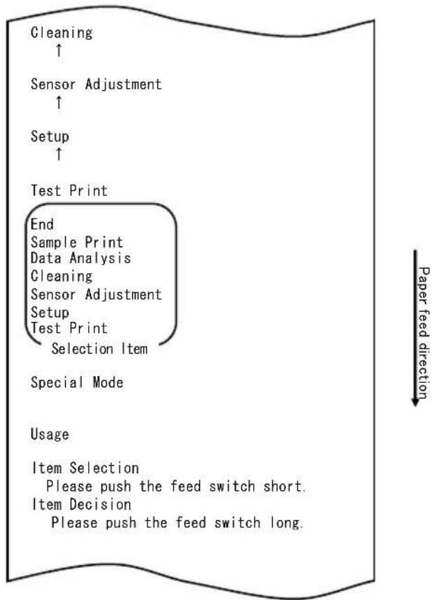
flowchart
graph TD
    A["Cleaning ↑"] --> B["Sensor Adjustment ↑"]
    B --> C["Setup ↑"]
    C --> D["Test Print"]
    D --> E["End Sample Print Data Analysis Cleaning Sensor Adjustment Setup Test Print Selection Item"]
    E --> F["Special Mode"]
    F --> G["Usage"]
    G --> H["Item Selection Please push the feed switch short. Item Decision Please push the feed switch long."]
(3) Press and hold down the FEED switch for one second or longer to accept the selection.
The printer prints the following when you accept the selection of "CLEANING":
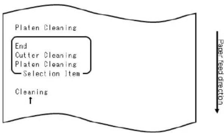
flowchart
graph TD
    A["Platen Cleaning"] --> B["End"]
    B --> C["Cutter Cleaning"]
    C --> D["Platen Cleaning"]
    D --> E["Selection Item"]
    E --> F["Cleaning"]
    F --> G["Paper feed direction"]
(4) Press the FEED switch briefly (one second or less) once to move to "CUTTER CLEANING."
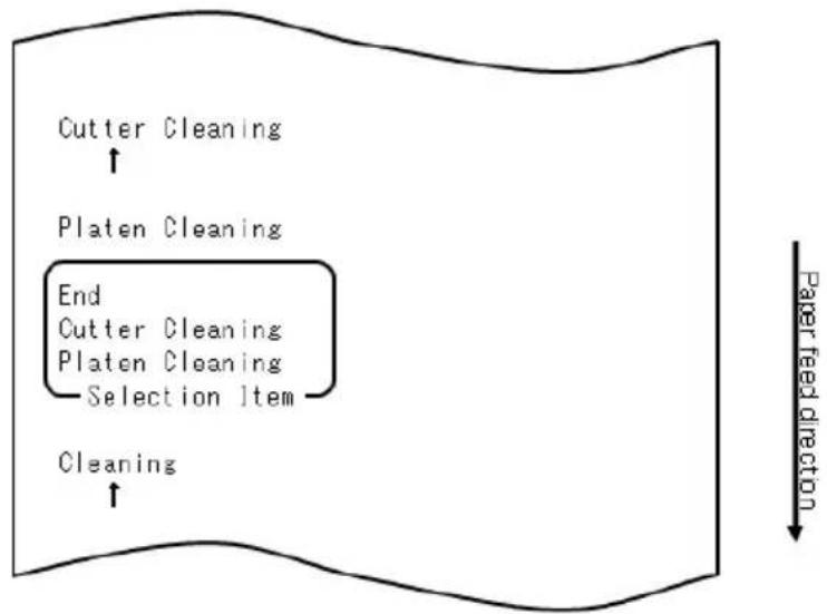
flowchart
graph TD
    A["Cutter Cleaning"] --> B["Platen Cleaning"]
    B --> C["End"]
    C --> D["Cutter Cleaning"]
    C --> E["Platen Cleaning"]
    E --> F["Selection Item"]
    F --> G["Cleaning"]
    G --> H["Paper feed direction"]
Then, press the FEED switch for one second or longer to accept the selection. The printer enters cutter cleaning mode. The printer prints the following and cuts the paper when it enters cutter cleaning mode:
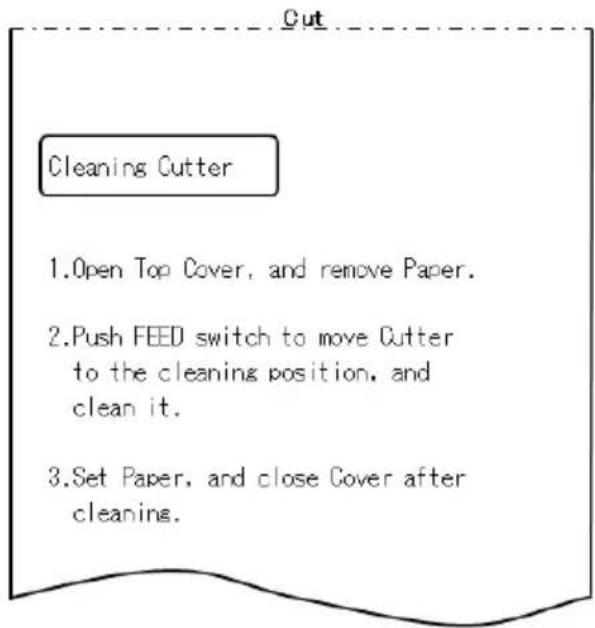
(5) After completing cleaning, reposition the roll paper, and close the top cover.
- Cleaning the Upper cutter
Using a general-purpose utility knife, flathead screwdriver, or similar tool, remove the adhesive matter adhering to the inner side and edge of the Upper cutter.
Note: Be very careful not to damage the edge of the Upper cutter when handling the utility knife or screwdriver. Also take care not to dent or otherwise damage the platen roller. A dent on the platen roller may result in incomplete printing or line feed errors.
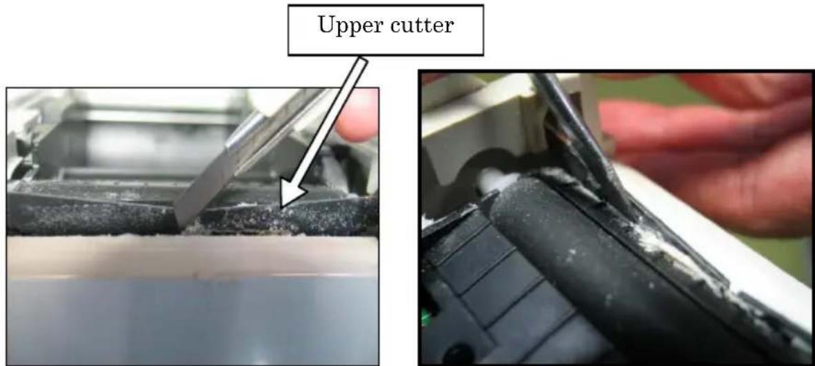
Using the cleaning sheet or a similar material, wipe off the adhesive matter adhering to the Upper cutter.
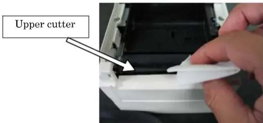
Note: Although the edge of the Upper cutter is not as sharp as the edges of the utility knives generally used in offices, there is a risk of injury to a finger that is moved while pressed directly against the edge of the cutter.
(7) After completing cleaning, reposition the roll paper, and close the top cover.
- Cleaning the Lower cutter
Using a general-purpose utility knife, flathead screwdriver, or similar tool, remove the adhesive matter adhering to the surface and edge of the Lower cutter.
Note: Be very careful not to damage the edge of the Lower cutter when handling the utility knife or screwdriver. Also take care not to dent or otherwise damage the platen roller. A dent on the platen roller may result in incomplete printing or line feed errors.
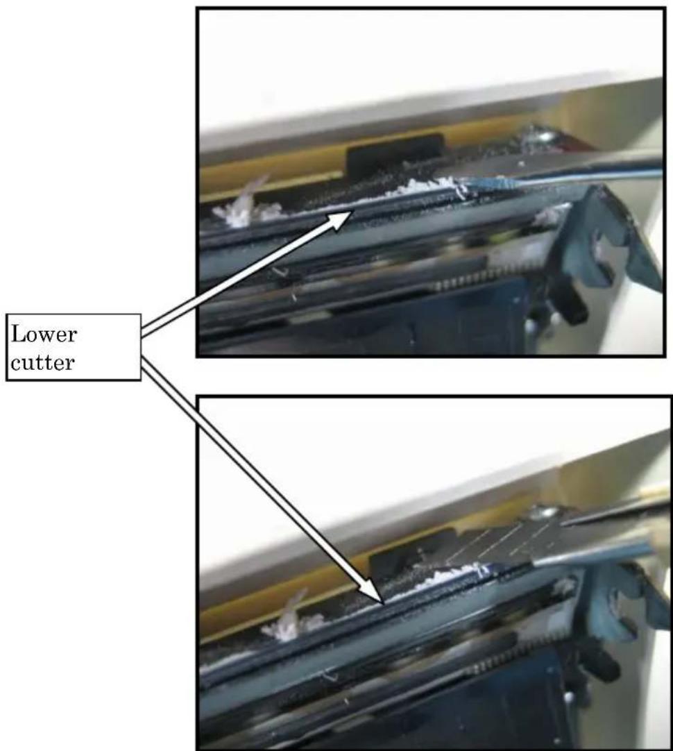
Using the cleaning sheet or a similar material, wipe off the adhesive matter adhering to the Lower cutter.
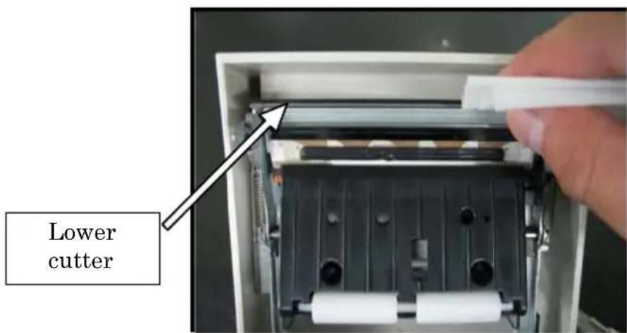
Note: Although the edge of the Lower cutter is not as sharp as the edges of utility knives generally used in offices, there is a risk of injury to a finger that is moved while pressed directly against the edge of the cutter.
(5) After completing cleaning, reposition the roll paper, and close the Top cover.
Note: Be careful when the printer is in cutter cleaning mode, because the Upper cutter is exposed. After completing cleaning, reposition the roll paper, and close the Top cover.
12. Interface
12-1. LAN Interface
(1) LAN interface connector
| Pin No. | Signal name | I/O direction | Signal line name |
| 1 | TX+ | Output | Output data |
| 2 | TX- | Output | Output data |
| 3 | RX+ | Input | Input data |
| 4 | N.C | - | - |
| 5 | N.C | - | - |
| 6 | RX- | Input | Input data |
| 7 | N.C | - | - |
| 8 | N.C | - | - |
(2) LEDs
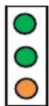
1 2 3
| No. | Display | Description |
| 1 10 | BASE-T link Light | goes on when printer recognizes connectiondestination as 10BASE-T |
| 2 | 100BASE-TXlink | Light goes on when printer recognizes connectiondestination as 100BASE-TX |
| 3 Status | Light goes on | for certain period (50 ms) uponpacket reception |
(3) DIP switches
Note: The DIP switches are provided for maintenance purposes. All DIP switches should be left OFF during normal operation.
| No. | ON | OFF |
| 1 - | Off (fixed) | |
| 2 | Setup information initialization | - |
| 3 | Setup information | - |
| 4 | Self-diagnosis printing | - |
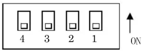
Procedure for initializing setup information
1) Turn off the printer power.
2) Set switch 2 to ON.
3) Turn on the printer power. Initialization takes about five seconds.
4) Turn off the printer power.
5) Set switch 2 to OFF.
Procedure for test printing from the LAN board
1) Turn off the printer power.
2) Set switches 3 and 4 to ON.
3) Turn on the printer power to start test printing.
4) Turn off the printer power.
5) Set switches 3 and 4 to OFF.
Note: Be careful when setting the DIP switches.
12-2. Dual Interface
(1) Type B Connector: 4 Pin
| Pin No. | Signal name I/O | direction Signal line name | |
| 1 | N.C | --- | |
| 2 | D-inB | Input/Output | D- |
| 3 | D+inB | Input/Output | D+ |
| 4 | SG1 | --- | Ground |
(2) Serial interface connector
| Pin No. | Signal name I/O | direction Function | |
| 1 | FG | --- Frame ground | |
| 2 | TXD | Output | Send data |
| 3 | RXD | Input | Receive data |
| 4 | RTS | Output | Send request |
| 5 | CTS | Input | Send permission |
| 6 | DSR | Input | Data set ready |
| 7 | SG | --- Signal ground | |
| 8 to 19 | N.C. | --- | Unused |
| 20 | DTR | Output | Data terminal ready |
| 21 to 24 | N.C. | --- | Unused |
| 25 | INIT | Input | Forced reset |
Notes 1: Use inch-screws to secure the connection.
Notes 2: Shielded USB cables must be used.
12-3. Drawer Kick Connector
| Pin No. | Signal name I/O | direction Signal | line name |
| 1 FG | Output | drawer frame ground | signal |
| 2 *DRD1 | Output | drawer kick drive | signal 1 |
| 3 DRSNS1 | Input | Drawer sense signal | 1 |
| 4 | +24V | Output | Drive power |
| 5 *DRD2 | Output | Drawer kick drive | signal 2 |
| 6 SG | Output | Drawer sense ground | signal |
Notes 1: "*" indicates a negative-logic signal.
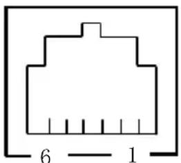
natural_image
Pure electrical connector pinout diagram without any text or symbolsConnecting side
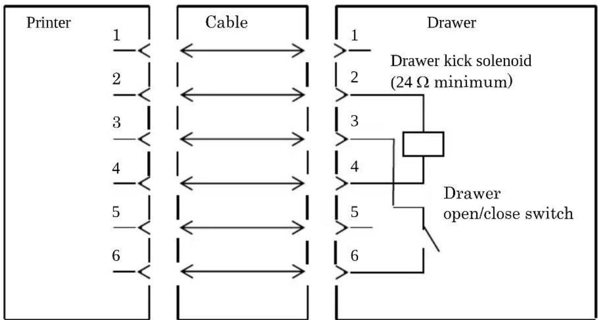
flowchart
graph LR
    subgraph Printer
        A1["1"] --> B1["Cable"]
        A2["2"] --> B1
        A3["3"] --> B1
        A4["4"] --> B1
        A5["5"] --> B1
        A6["6"] --> B1
    end

    subgraph Cable
        B1 <--> C1["1"]
        B1 <--> C2["2"]
        B1 <--> C3["3"]
        B1 <--> C4["4"]
        B1 <--> C5["5"]
        B1 <--> C6["6"]
    end

    subgraph Drawer
        D1["1"] --> E1["2"]
        D1 --> F1["3"]
        D1 --> G1["4"]
        D1 --> H1["5"]
        D1 --> I1["6"]
        D1 --> J1["Drawer kick solenoid (24 Ω minimum)"]
        J1 --> K["Drawer open/close switch"]
    end
Notes : Use a shielded drawer cable.
Notes : Two drives cannot be driven simultaneously.
Notes :The drawer on/off time must be specified using t1 and t2 in the pulse generation command (ESC p m t1 t2).
Notes : The drawer drive duty must be as follows:
ON-time/(ON-time + OFF-time) ≤ 0.2
Notes :The drawer power must always be supplied from the printer power supply unit via connector pin 4.
Notes :The resistance of the drawer kick solenoid must be at least 24Ω. If a solenoid with a lower resistance is used, the solenoid might be destroyed by over current.
Notes :This product uses a modular connector as a dedicated connector for the cash drawer or customer display terminal. The connector must not be connected with a connector that leads to a public switched line or other such destination.
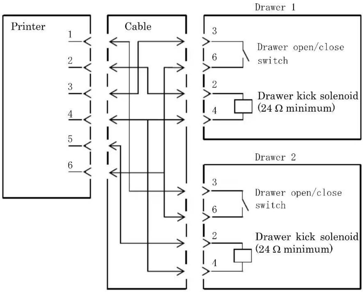
flowchart
graph TD
    subgraph Printer
        A["1"] --> B["Cable"]
        C["2"] --> B
        D["3"] --> B
        E["4"] --> B
        F["5"] --> B
        G["6"] --> B
    end

    subgraph Cable
        B <--> H["3"]
        B <--> I["6"]
        J["4"] --> K["2"]
        J --> L["4"]
        M["3"] --> N["3"]
        M --> O["6"]
        P["2"] --> Q["2"]
        P --> R["4"]
        S["4"] --> T["4"]
        U["3"] --> V["3"]
        U --> W["6"]
        X["2"] --> Y["2"]
        X --> Z["4"]
        AA["4"] --> AB["4"]
    end

    subgraph Drawer 1
        H --> AC["Drawer open/close switch"]
        I --> AD["Drawer kick solenoid (24 Ω minimum)"]
        J --> AE["4"]
    end

    subgraph Drawer 2
        H --> AF["Drawer open/close switch"]
        I --> AG["Drawer kick solenoid (24 Ω minimum)"]
        J --> AH["4"]
    end
12-4. Specifications of Power Supply
(1) Operating voltage : DC 24V±10%
(2) Current consumption :- Standby: 4.5W or less/0.2A on average
Note: Maximum drawer kick drive current: 1A Two drawer kicks must not be driven simultaneously.
- Average current consumption Operating: About 44W/1.5A on average
(at 24V, 25°C, print density setting 100%, paper width 80mm, print duty 9%)
Arrangement of power connector pins
| Pin No. | Signal name |
| 1 | +24 |
| 2 | SG |
| 3 | N.C |
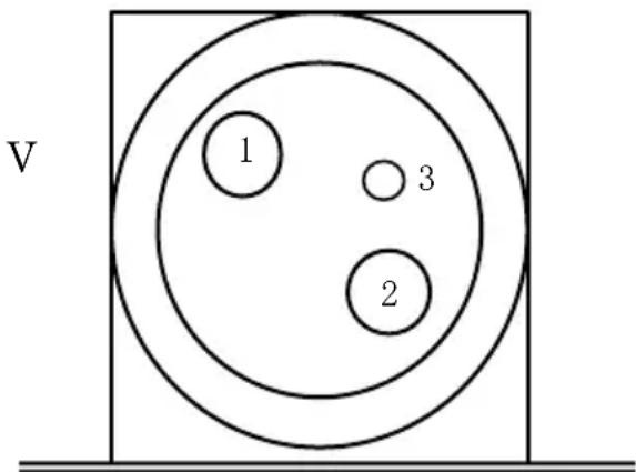
Note : Use our AC adapter to supply power.
Note : If our AC adapter is not used (power supply is supplied by the user), problems such as bad print quality, electromagnetic interference, or circuit noise may occur. In such cases, take note of the following points:
- Use an AC adapter whose capacity corresponds to the printing rate that will actually be used.
- Ensure in advance that there are no problems such as static electricity, electromagnetic interference, circuit noise, etc.
13. Specifications
13-1. General Specifications
(1) Print method: Direct line thermal printing system
(2) Dot resolution: 8 dots/mm (0.125 mm)
(3) Paper width: 83 mm, 80 mm, or 70 to 25.4 mm (by units of 1 mm)
- The paper width is set to 70 mm at the time of shipment from the factory.
- If the roll paper partition attached to the printer is removed, you can select a paper width of up to 83 mm.
Note: Paper with a width within a range of 71 to 79 mm cannot be used.
(4) Print speed:
single-color thermal paper
Maximum print speed: 260 mm/s
| Paper width Print speed |
| 83 to 58 mm Up to 260 mm/s |
| 57 to 38 mm Up to 180 mm/s |
| 37 to 25.4 mm Up to 80 mm/s |
- The print speed is set to 140 mm/s at the time of shipment from the factory.
two color thermal paper
Maximum print speed: 115 mm/s
| Paper width Print speed |
| 83 to 58 mm Up to 115 mm/s |
| 57 to 38 mm Up to 115 mm/s |
| 37 to 25.4 mm Up to 80 mm/s |
(5) Relationship between number of print columns and character size
Body Face
| For paper 58mm wide For paper 60mm wide | |||
| 32 column printing 35 | column printing 36 | column printing | |
| ANK: Font A 32 | columns: 12x24 35 columns: 12x24 36 columns: 12x24 | ||
| ANK: Font B | 38 columns: 10x2442 columns: 9x24 | 42 columns: 10x2446 columns: 9x24 | 43 columns: 10x2448 columns: 9x24 |
| ANK: Font C 48 | columns: 8x16 52 columns: 8x16 54 columns: 8x16 | ||
| Kanji: Font A 16 | columns: 24x24 17 columns: 24x24 18 columns: 24x24 | ||
| Kanji: Font B 19 | columns: 20x24 21 columns: 20x24 21 columns: 20x24 | ||
| Kanji: Font C 24 | columns: 16x16 26 columns: 16x16 27 columns: 16x16 | ||
| ANK: Font A Extension Font | 32 columns: 12x24 35 columns: 12x24 36 columns: 12x24 | ||
| ANK: Font B Extension Font | 38 columns: 10x2442 columns: 9x24 | 42 columns: 10x2446 columns: 9x24 | 43 columns: 10x2448 columns: 9x24 |
Body Face
| For paper 80mm wide For paper 83mm wide | |||
| 42 column printing 48 | column printing 53 | column printing | |
| ANK: Font A 42 | columns: 12x24 48 columns: 12x24 53 columns: 12x24 | ||
| ANK: Font B | 51 columns: 10x2456 columns: 9x24 | 57 columns: 10x2464 columns: 9x24 | 64 columns: 10x2471 columns: 9x24 |
| ANK: Font C 64 | columns: 8x16 72 columns: 8x16 80 columns: 8x16 | ||
| Kanji: Font A 21 | columns: 24x24 24 columns: 24x24 26 columns: 24x24 | ||
| Kanji: Font B 25 | columns: 20x24 28 columns: 20x24 32 columns: 20x24 | ||
| Kanji: Font C 32 | columns: 16x16 36 columns: 16x16 40 columns: 16x16 | ||
| ANK: Font A Extension Font | 42 columns: 12x24 48 columns: 12x24 53 columns: 12x24 | ||
| ANK: Font B Extension Font | 51 columns: 10x2456 columns: 9x24 | 57 columns: 10x2464 columns: 9x24 | 64 columns: 10x2471 columns: 9x24 |
(6) Alphanumeric characters (95), extended graphics (128 x 20 pages), international characters (48)
Kanji JIS-1990 (6879), special characters (845)
(7) Dimensions of fonts
| Body Face Letter Face | ||||
| (W)x(H) dot (W)x(H) mm (W)x(H) dot (W)x(H) mm | ||||
| ANK: Font A 12 x 24 1.5 x 3.0 11 x 22 1.375 x 2.75 | ||||
| ANK: Font B | 10 x 249 x 24 | 1.25 x 3.01.125 x 3.0 | 9 x 179 x 17 | 1.125 x 2.1251.125 x 2.125 |
| ANK: Font C 8 x 16 1.0 x 2.0 8 x 13 1.0 x 1.625 | ||||
| Kanji: Font A 24 x 24 3.0 x 3.0 24 x 24 3.0 x 3.0 | ||||
| Kanji: Font B 20 x 24 2.5 x 3.0 18 x 24 2.25 x 3.0 | ||||
| Kanji: Font C 16 x 16 2.0 x 2.0 15 x 15 1.875 x 1.875 | ||||
| ANK: Font A Extension Font | 12 x 24 1.5 x 3.0 12 x 24 1.5 x 3.0 | |||
| ANK: Font B Extension Font | 10 x 249 x 24 | 1.25 x 3.01.125 x 3.0 | 9 x 229 x 22 | 1.125 x 2.751.125 x 2.75 |
(8) External views
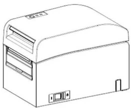
natural_image
Line drawing of a rectangular electronic device with lid and ventilation slots (no text or symbols)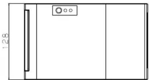
natural_image
Simple line drawing of a door with a vertical panel and circular button, no text or symbols present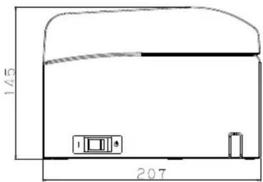
Paper guide opened

natural_image
Line drawing of a portable electronic device with ventilation slots and control buttons (no text or symbols)Paper guide
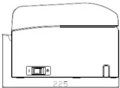
natural_image
Simple line drawing of a kitchen appliance with a refrigerator and a battery, labeled '225' at the base (no text or symbols on the diagram itself)13-2. Cutter Specifications
Cutting mode: Full cutting
Note : For printing on label paper, use only partial cutting. If full cutting is used in such cases, paper cutting performance will deteriorate faster because of the greater adverse effect of adhesive matter.
Note : Paper cutting performance may deteriorate faster with the use of label paper because of its adhesive matter. Clean the cutter blade periodically to remove the adhesive matter.
Note : Full cutting may lead to irregularities at the center of the cutting surface. If paper fiber remains at these locations, this may eventually lead to incomplete cutting at these locations.
Note : In full cutting mode, the printed paper must be removed each time that one sheet is printed. Otherwise, printed paper remains in the automatic cutter section and may cause a cutting error.
Note : The maximum number of successive cuts by the cutter is 30 cuts per minute (at least two seconds per cut). Using the cutter at a higher rate may cause a failure.
13-3. Paper Supply Specifications
(1) Loading method: Rolls are loaded manually.
(2) Paper near end: Detected when only a little paper is left.
| (μm) | The outside core diameterof roll paper is 32 mm. Paper thickne | |
| Sensed diameter(mm) | Remaining paper length(m) | |
| 75 to 150 About 40 | 75 to 150 | |
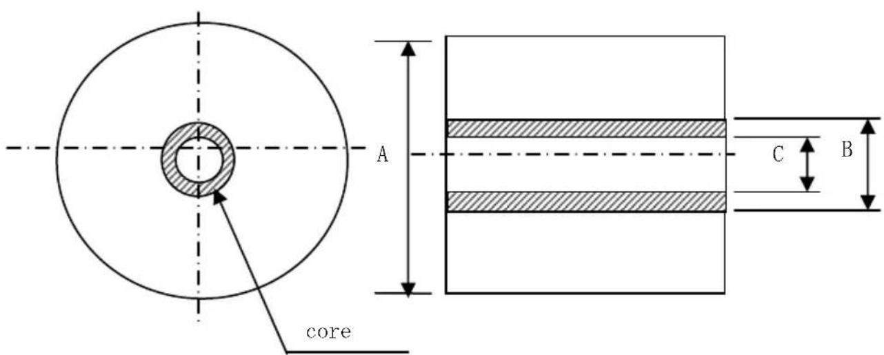
Note: The above values (i.e., sensed diameter, remaining paper length) are theoretical values. These values vary depending on actual conditions, including the paper roll condition and paper thickness.
Note: The outside core diameter is assumed to be 32 ~mm . If roll paper with an outside core diameter of other than 32 ~mm is used, the paper-near-end detection accuracy deteriorates.
Note: If roll paper with an outside core diameter of less than 32 mm is used, a transport error may occur when the cutter cuts the paper in full cutting mode and reaches the core.
13-4. Interface Specifications
(1) LAN (IEEE802.3 (10BASE-T)/IEEE802.3U (100BASE-TX))
(2) Dual (Conforms to USB 1.1 and RS-232C)
13-5. Environment Specifications
(1) Temperature
When operating : Operation guaranteed from 0°C to 40°C.
Printing guaranteed from 5°C to 35°C.
When no operating : -5°C to 60°C
When being transported or stored : -20°C to 60°C
(While packaged)
(2) Humidity
When operating : Operation guaranteed from 10% to 95%RH
(no
condensation)
Printing guaranteed from 10% to 85%RH
(no
condensation)
When no operating : 8% to 95% RH (no condensation)
When being transported or stored : 5% to 95% RH
(While packaged) (no condensation)
(3) Maximum wet bulb temperature : 29°C or less
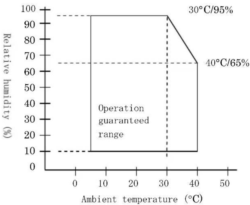
line
| Ambient temperature (°C) | Relative humidity (%) | | ------------------------ | --------------------- | | 0 | 10 | | 30 | 10 | | 40 | 65 |13-6. Specifications of Reliability
(1) Printer life
Feed of 25 million lines (Specified thermal paper) or 5 years
(2) Head
Running life : 150km (Specified single-color thermal paper) 75km (Specified dual-color thermal paper)
Pulse life : 150 million pulses
* Scratches caused by foreign matter are excluded.
(3) Cutter
Full cutting
- Receipt cutting: 2,000,000 cuts (for the recommended paper with a thickness of 75 m) 500,000 cuts (for the recommended paper with a thickness of 75 to 150 m)
- Label cutting
1,000,000 cuts (cutting in base area) 500,000 cuts (cutting of full-sheet labels)
(The life can be lengthened to 1,000,000 cuts through cleaning of the cutter blade.)
Note : For cutting of die-cut label paper, the base area between labels must be cut.
Note : Paper cutting performance may deteriorate faster with the use of label paper because its adhesive matter adheres to the cutter blade. Clean the cutter blade periodically.
14. Roll Paper Unit
14-1. Outline
The wide roll paper unit is optional.
A maximum 200 -mm roll can be used.
Mount to the rear of the printer to use.
14-2. Nomenclature
Partition
Adjust position according to paper width.
Protruding printer connector
Roll paper shaft (enclosed)
※Roll paper shaft for 1.5 inches and two-inch diameter is an option sold separately.
Cable clamps
Used to clamp the interface and AC adapter cable.
PNE sensor cable
Connects to the printer.
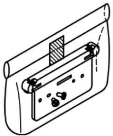
natural_image
Line drawing of a mechanical device with a handle and internal components (no text or symbols)Printer connector fitting Fitting mounting screws (x2)
Instruction sheet
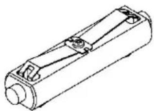
natural_image
Technical line drawing of a cylindrical mechanical component with mounting holes and internal channels (no text or symbols)Roll paper shaft (One-inch diameter)
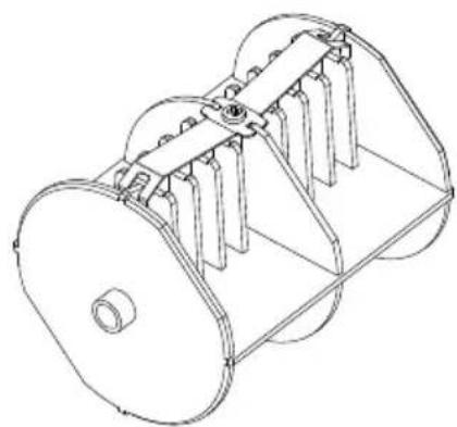
natural_image
Technical line drawing of a mechanical component with multiple blades and a central hub (no text or symbols)Roll paper shaft (Three-inch diameter)
14-3. Paper Specifications
(1) 83mm paper width... 8380mm_-1.0^0 paper width... 80mm_-1.0^0
70\~25.4mm (1mm unit) paper width: 25.470mm\~1.0
(2) External dimensions (A): 200±0.5mm max.
(3) Paper width: 75 to 150μm
(4) Roll core dimensions: Inside diameter (C) 25.4±0.5mm / external diameter (B) 32±0.5mm (One inch Roll paper)
Inside (C) 76.2± 0.5mm diameter / external diameter (B) 82± 0.5mm (Three inch Roll paper)
(5) Coloration surface: outside of paper roll
(6) Runout processing: Do not fix the core using glue, etc. Further, do not fold the paper at the end of the runout.
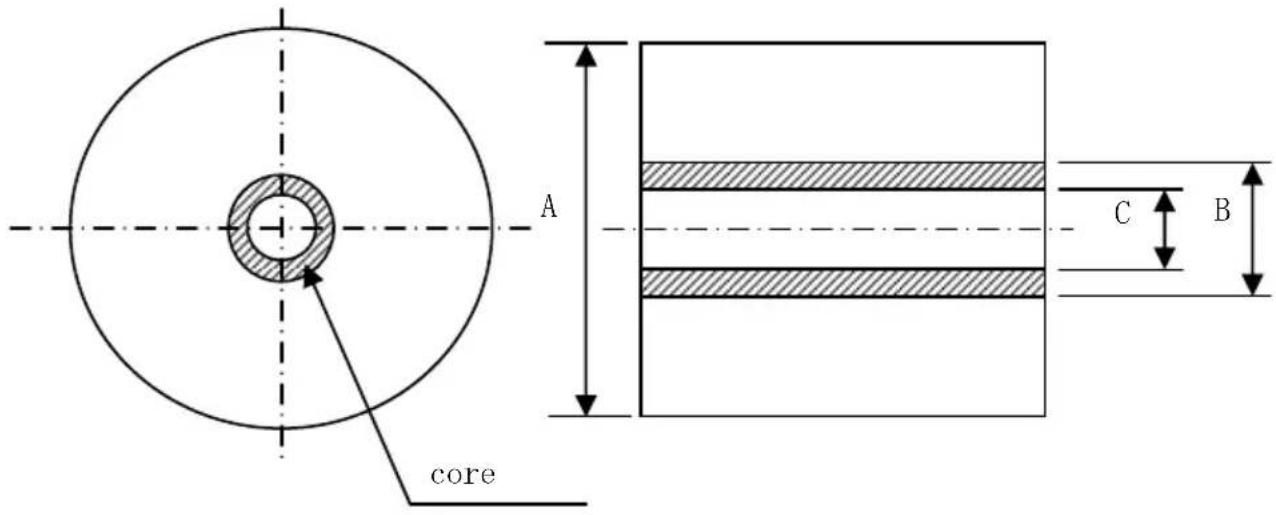
Note: Do not use rolls that have rough sides or sides from which pieces of paper extrude. Using such rolls could cause a printer failure.
14-4. Roll Paper Feed Specifications
(1) Feed method: manual setting
(2) Paper near end: Detected when there is little remaining paper.
The remaining paper that can be detected is described below.
| Paper thickness (μm) | External Core diameter (B) (mm) | Detection diameter (A) (mm) | Remaining paper (m) |
| 75 | φ82 | Approx. φ100 | 20 to 30 |
| 150 | φ82 | Approx. φ100 | 10 to 20 |
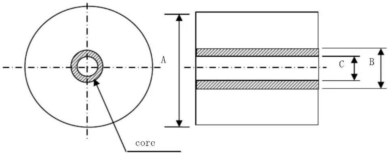
Note: The above values (i.e., sensed diameter, remaining paper length) are theoretical values. These values vary depending on actual conditions, including the roll paper condition and paper thickness.
14-5. Roll Paper Unit Installation Procedure
When connecting or removing, turn OFF the power supply switches to the printer and all devices connected to the printer before starting work, and remove the plug for the AC adapter power supply cable from the outlet.
(1) Remove the connector cover at the rear of the printer.
Open the connector cover and warp the middle cover in the direction of the arrow ①. Then, remove the rotary supporting point part of the connector cover in the order of right side ② and the left side ③.
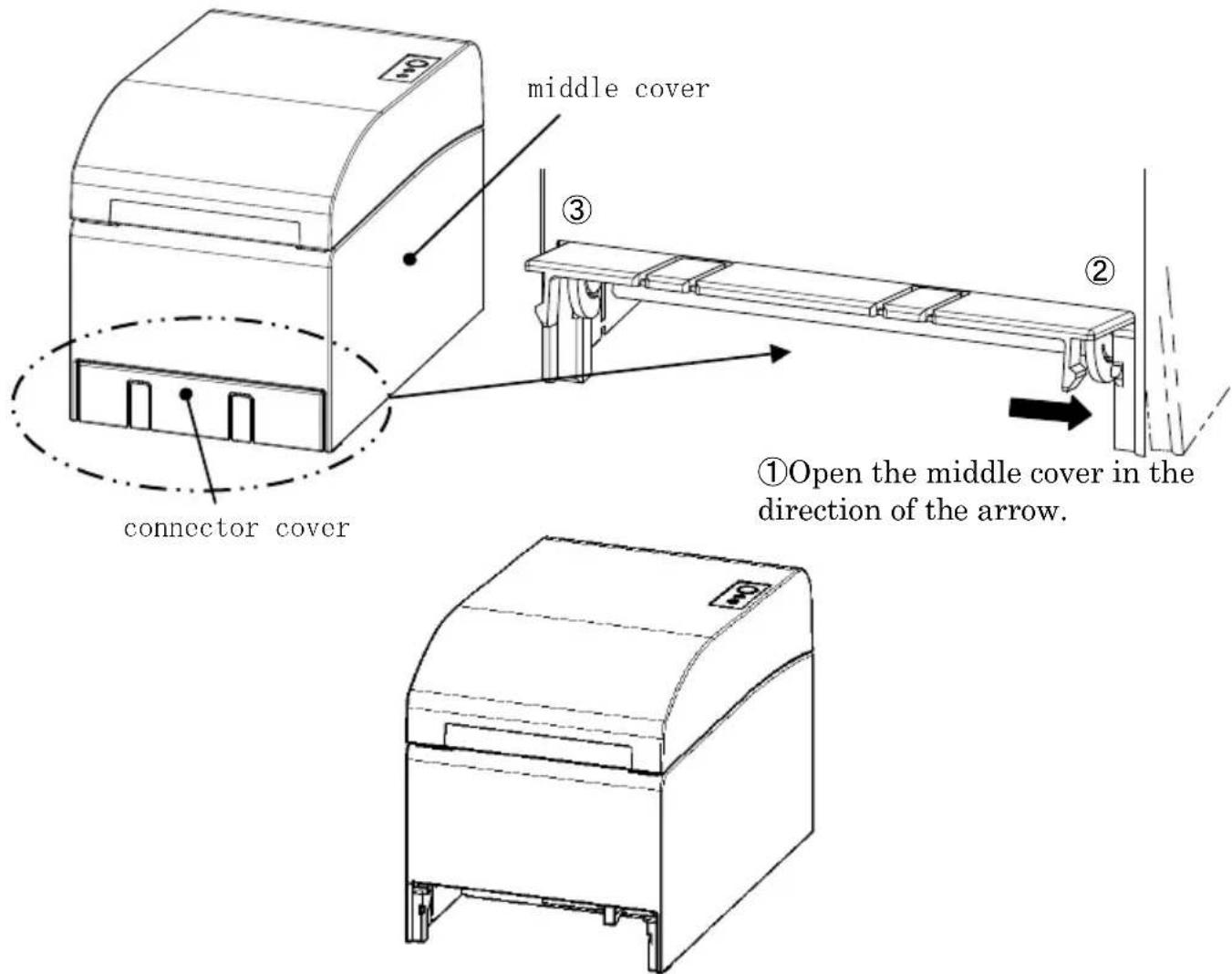
View after the connector cover is removed
(2) Mount the enclosed fitting for the printer connection using the enclosed screws.
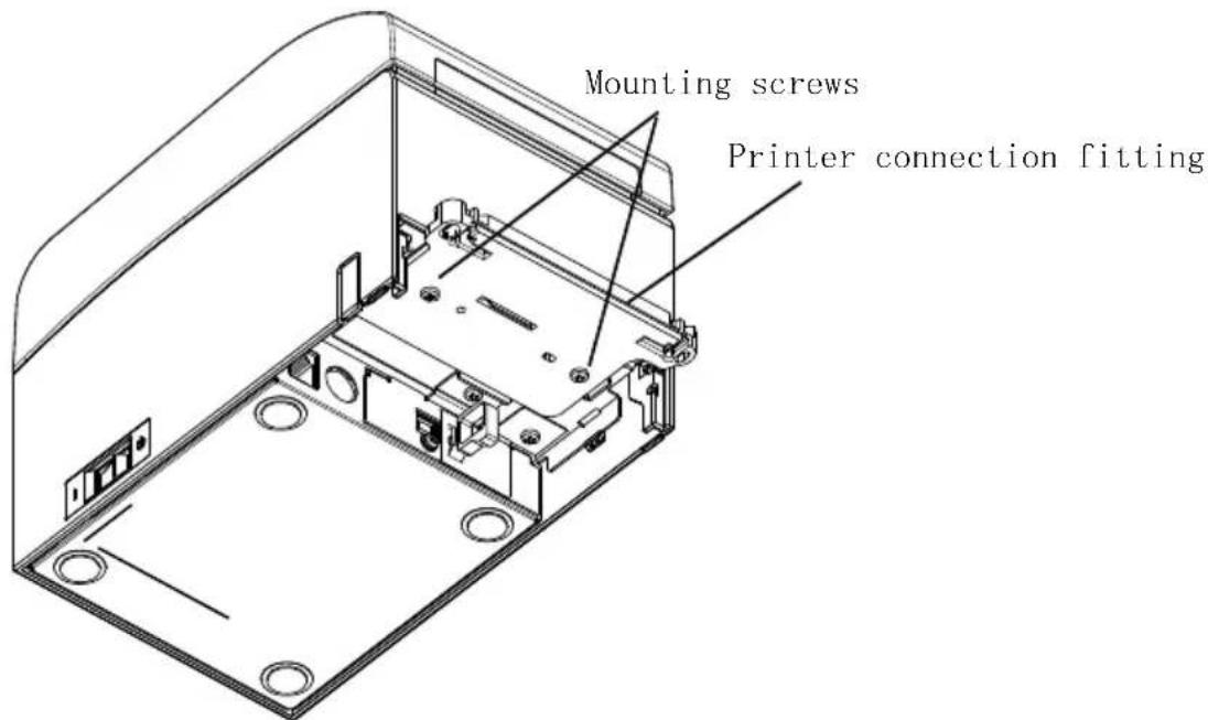
(3) Connect the sensor cable, interface cable, and AC adapter cable for the wide roll paper unit to the connector at the rear of the printer.
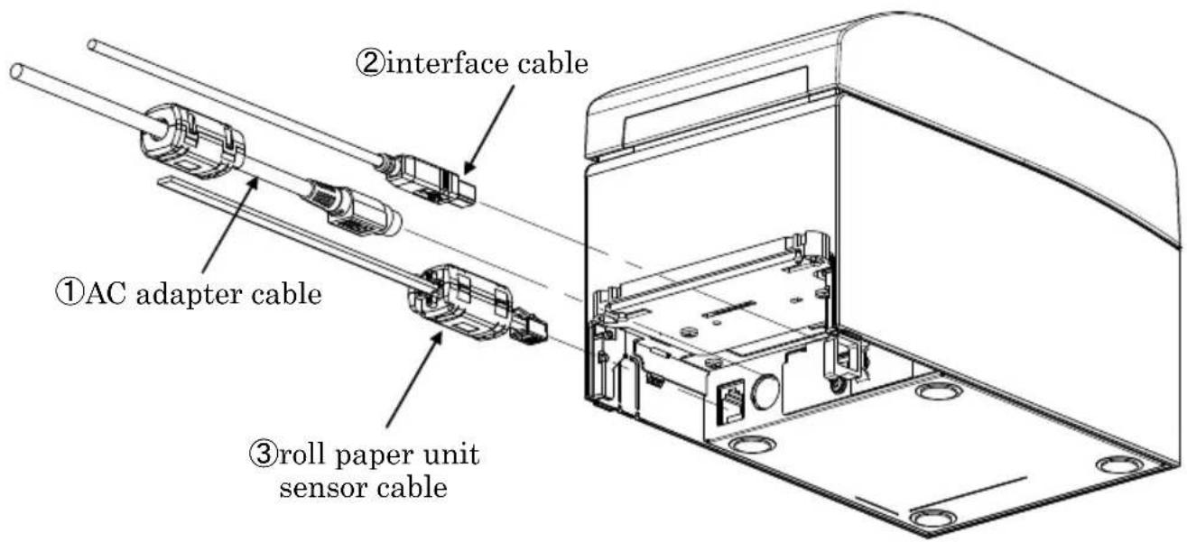
Note: For how to connect the AC adapter cable, see Section 4-2 Connecting AC Adapter.
Note: When you connect cables, connect in the following order: ① AC adapter cable -> ② Interface cable -> ③ Sensor cable.
(4) Connect the printer to the wide roll paper unit.
Insert the holes on the left and right of the printer connector fitting into the left and right protrusions on the wide roll paper unit connector to connect.
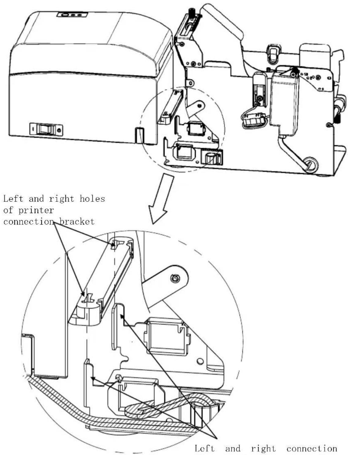
Left and right connection flanges of roll paper unit
(5) Route the sensor cable, interface cable, and AC adapter cable of the roll paper unit through the cable clamps from the inside to the outside of the roll paper unit as shown in the diagram below.
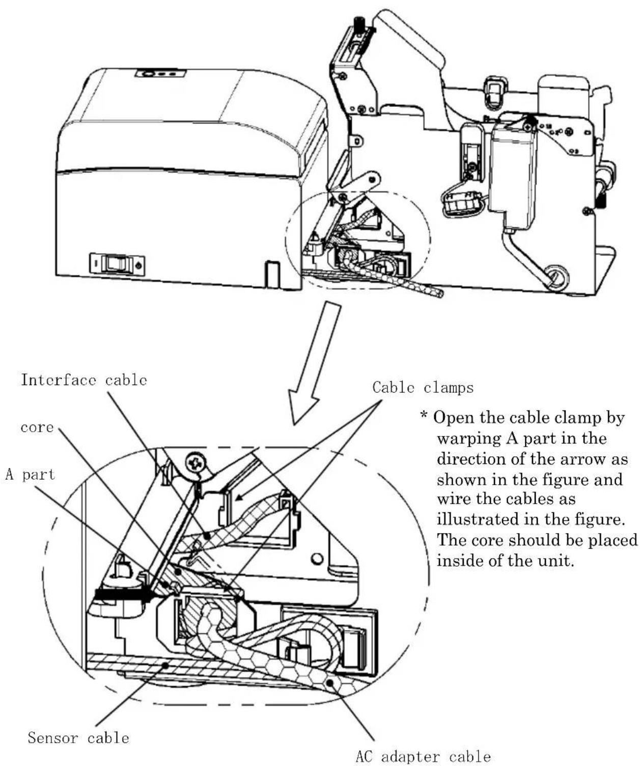
(6) Take up the slack in the sensor cable between the roll paper unit and printer by securing the excess length with a cable clamp as shown in the diagram below.
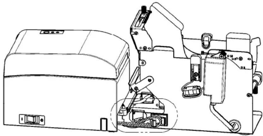
natural_image
Technical line drawing of a mechanical device with internal components and mounting bracket (no text or symbols)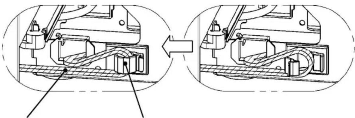
natural_image
Technical diagram showing mechanical assembly before and after transformation, with no visible text or symbolsSensor cable Secured with cable clamp
14-6. Method of setting PNE sensor
Select PNE sensor position by each size of roll paper core diameter, then pinch and fix the screw.
1 is default position. (The following chart is a position where the paper tube of one-inch diameter is set.)
1 : Position for 1.0 inch core size
1.5 : Position for 1.5 inch core size
2 : Position for 2.0 inch core size
3 : Position for 3.0 inch core size
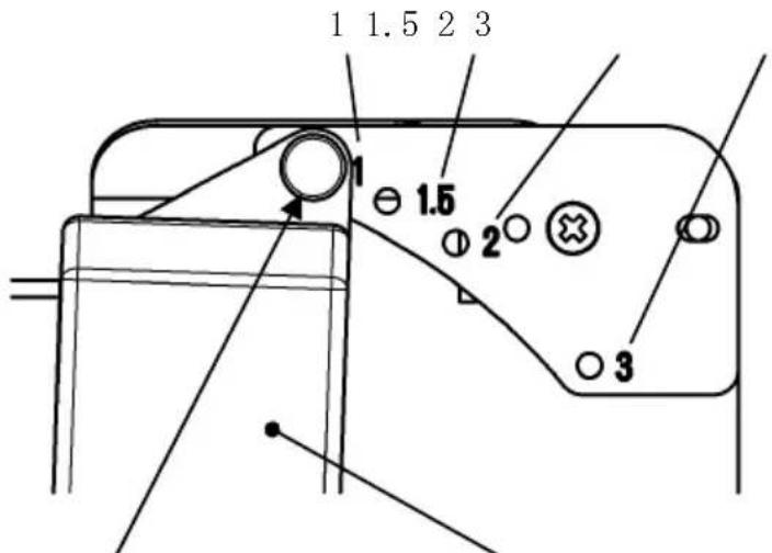
Screw PNE sensor
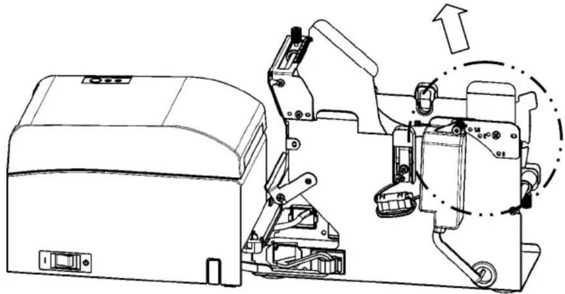
natural_image
Technical line drawing of a mechanical device with internal components and an upward arrow indicating motion (no text or symbols present)14-7. Method of setting guide plate
Loosen the knurled screw of the guide plate of each kind of the roll paper core size, set the set position, then fix the knurled screw.
1 is default position. (The following chart is a position where the core of one-inch diameter is set.)
1 : Position for 1.0 inch core size
1.5 : Position for 1.5 inch core size
2 : Position for 2.0 inch core size
3 : Position for 3.0 inch core size
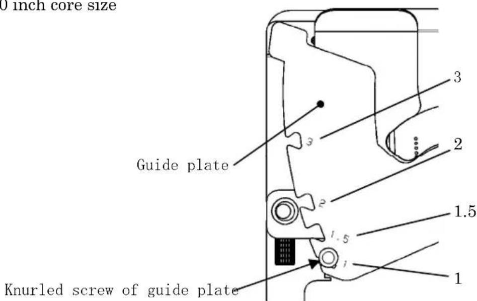
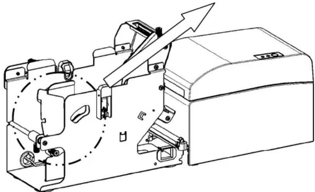
natural_image
Technical line drawing of a mechanical device with internal components and an arrow indicating motion (no text or symbols)14-8. Setting the Roll Paper
(1) Insert the paper roll to the included paper roll shaft core and set them in the large diameter paper roll unit.
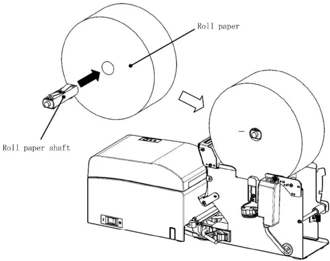
Note: To load a new roll paper, first remove the tape and the glued portion at the beginning of the roll.
Note: The printer cannot print on the glued portion of the paper, so remove about one turn of the roll paper from the beginning. Any adhesive or other matter remaining from the glue may stick to the thermal head and cause a problem such as voids on printouts. For this reason, be sure to remove the glued portion of the paper.
Note: There is a direction of the installation when the paper is installed. Please install it like the clause 14-8-(3).
Note : The roll paper must have no deformities. Using roll paper such as that shown in the figure below may cause a paper jam, uneven printing, or other printing problem.
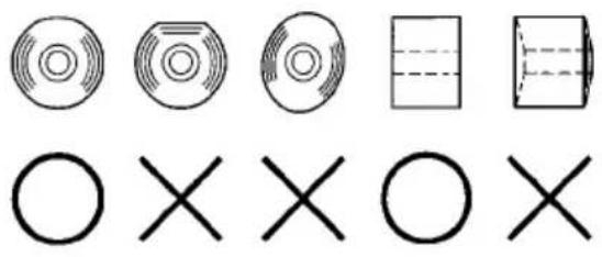
Note : If the loaded roll paper is loose (slack) as shown below, take up the slack before printing on the paper. Printing on roll paper that is loose may cause a paper jam, uneven printing, or other printing problem, which will prevent the printer from detecting paper near end conditions.
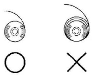
natural_image
Simple line drawings of a circular object with a cross symbol below (no text or labels)(2) Set the paper width by positioning the partitions in the roll paper unit.
[1] Orient the paper roll along the direction arrow A.
[2] Loosen the knob screws front and back that fix the partition.
[3] Align the partition to the width of the paper roll, and slide in the direction of the arrows B.
[4] Fix the partition leaving a slight gap as shown in the diagram.
Front: Leave a gap of one gradation on the scale between the partition and the paper roll, and then tighten the (front) knob screws to fix.
Back : Leave a gap of one 1 to 3mm using the scale between the partition and the paper roll, and then tighten the (back) knob screws to fix.
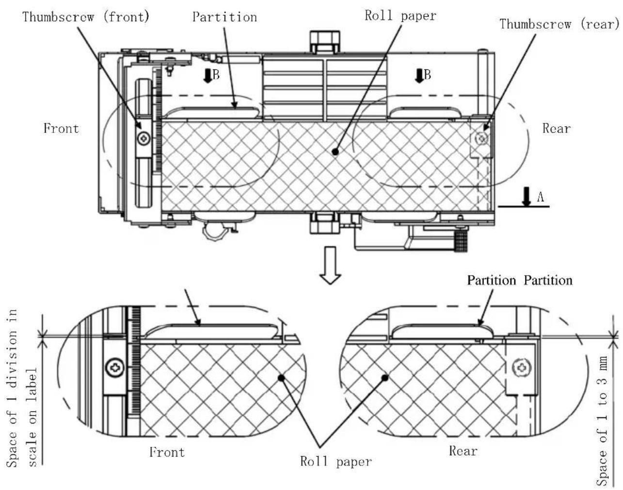
(3) Pass the roll paper under the guide roller. Lift the guide roller. Then, with the printer top cover closed, insert the leading edge of the paper into the rear of the printer.

Fig. a
Note : When the rolled paper is guided on top of the guide roller as illustrated in Figure b shown below, the paper may not get through. Make sure that the paper is guided under the guide roller as in Figure a shown above.
Note : If a paper roll is set as illustrated in Figure c shown below, its thermal surface will be opposite and that nothing will be printed. Make sure to set a paper roll as in Figure a shown above.
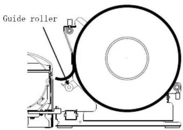
Fig.b Fig.c
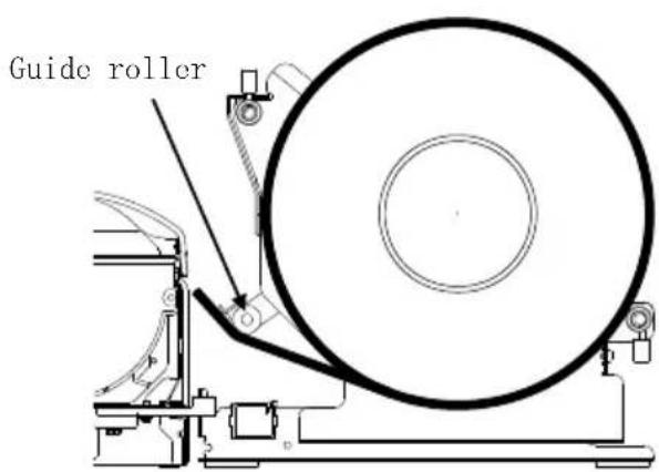
×
(4) Open the top cover, and pull out the leading edge of the paper from the front of the printer.
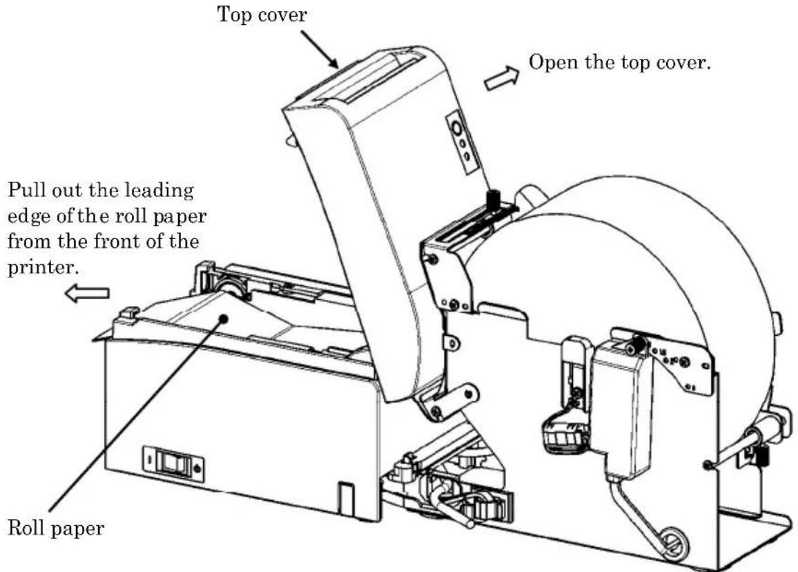
(5) After finishing setting the paper roll, close the top cover.
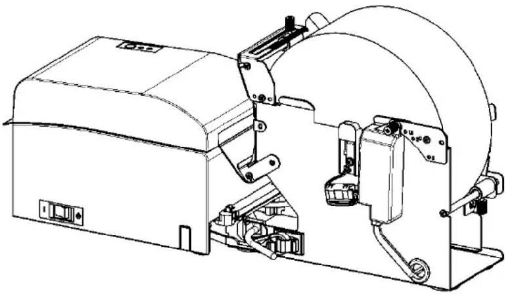
natural_image
Technical line drawing of a mechanical device with no visible text or symbols14-9. Roll Paper Unit Appearance
(When connected to the printer.)
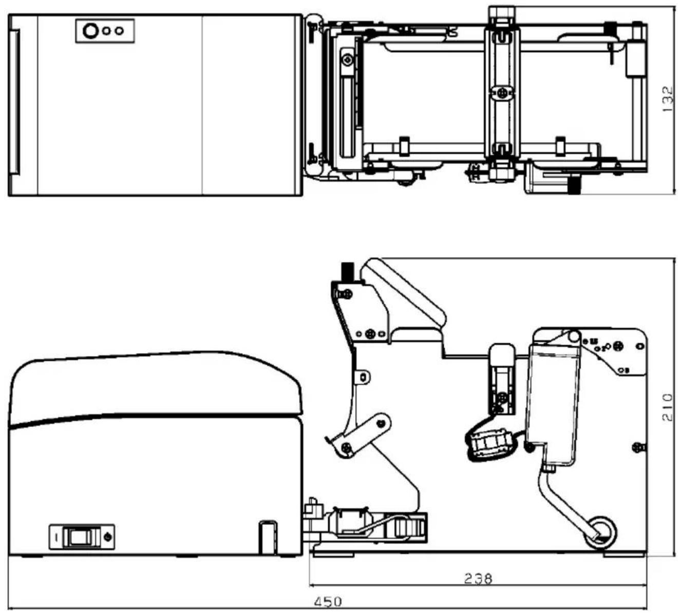
Oki Systems (UK) Ltd
Blays House
Wick Road
Egham
Surrey
TW20 0HJ
Tel: +44 (0) 1784 274300
Fax: +44 (0) 1784 274301
http://www.oki.co.uk
Oki Systems Ireland Limited
The Square Industrial Complex Tallaght
Dublin 24
Tel: +353 (0) 1 4049590
Fax: +353 (0)1 4049591
http://www.oki.ie
Oki Systems Ireland Limited - Northern Ireland
19 Ferndale Avenue
Glengormley
BT36 5AL
Northern Ireland
Tel: +44 (0) 7767 271447
Fax: +44 (0) 1 404 9520
http://www.oki.ie
Technical Support for all Ireland:
Tel: +353 1 4049570
Fax: +353 1 4049555
E-mail: tech.support@oki.ie
OKI Systems (Czech and Slovak), s.r.o.
Futurama Business Park -
Sokolovská 651/136A
186 00 Praha 8
Czech Republic
Tel: +420 224 890158
Fax:+420 22 232 6621
Website: www.oki.cz, www.oki.sk
Albania, Bosnia, Bulgaria, Croatia,
Cyprus, Estonia, Greece, Israel,
Latvia, Lithuania, Macedonia,
Romania, Serbia, Slovenia
CEE Export Group: OKI Systems (Poland) Ltd
ul. Domaniewska 42
02-672 Warsaw
Poland
Tel: +48 (0) 22 448 65 00
Fax: +48 (0) 22 448 65 0
E-mail: tech@oki.com.pl
Platinum Business Park II, 3rd Floor
ul. Domaniewska 42
02-672 Warsaw
Poland
Tel: +48 22 448 65 00
Fax: +48 22 448 65 01
Website: www.oki.com.pl
E-mail: oki@oki.com.pl
Hotline: 0800 120066
E-mail: tech@oki.com.pl
OKI Systems Rus, LLC (Russia)
Sector B, 3rd Floor, Svyatogor-4
Business Center10/4, Letnikovskaya
str.115114, Moscow
Tel: +7 495 276 5060
Fax: +7 495 258 6070
e-mail: info@oki.ru
Website: www.oki.ru
Technical support:
Tel: +7 495 564 8421
e-mail: tech@oki.ru
Raisy Opkinoy Street,8
Building B, 2 ^nd Floor,
Kiev 02002
Ukraine
Tel: +380 44 537 5288
e-mail: event@oki.ua
Website: www.oki.ua
Oki Systems (Belgium)
Medialaan 24
1800 Vilvoorde
Helpdesk: 02-2574620
Fax: 02 2531848
Website: www.oki.be
OKI Systems (Danmark) a·s
Herstedøstervej 27
2620 Albertslund
Danmark
Oki Systems (Norway) AS
Tevlingveien 23
N-1081 Oslo
Tel: +47 (0) 63 89 36 00
Telefax: +47 (0) 63 89 36 01
Website: www.oki.no
Var vänlig kontakta din
Oki Systems (Sweden) AB
Borgafjordsgatan 7
Box 1193
164 26 Kista
Tel. +46 (0) 8 634 37 00
e-mail: info@oki.se
Website: www.oki.se
2000 Bishops Gate Blvd.
http://WWW.OKIPRINTINGSOLUTIONS.COM
http://my.okidata.com
Oki Data Americas Inc.(Canada • Canadá)
4140B Sladeview Crescent Unit 7 & 8
Mississauga, Ontario
Canada L5L 6A1
Tél: 1-905-608-5000
Téléc: 1-905-608-5040
http://WWW.OKIPRINTINGSOLUTIONS.COM
Oki Data Americas Inc.(América Latina (OTRO))
2000 Bishops Gate Blvd.
HTTP://www.okiprintingsolutions.com
Argentina/ Chile/ Paraguay/ Perú/ Uruguay
Oki Data Americas, Inc.
Sucursal Argentina
Ugarte 3610 Piso 4°(1605) Olivos
Buenos Aires, Argentina
TEL: +54 11 5288 7500
Fax: +54 11 5288 7599
Colombia/ Ecuador/ Venezuela/ Centroamérica y Caribe Oki Data Americas, Inc.
Sucursal Colombia
1168/81-82 Lumpini Tower,
27th Floor Rama IV Road
Tungmahamek, Sathorn
Bangkok 10120
Tel: (662) 679 9235
Fax: (662) 679 9243/245
http://www.okisysthai.com
Oki Data(Australia) Pty Ltd.
Level1 67 Epping Road, Macquare Park
NSW 2113, Australia
Tel: +61 2 8071 0000
(Support Tel: 1800 807 472)
Fax: +61 2 8071 0010
http://www.oki.com.au
OKI Data New Zealand
8 Antares Place Rosedale,
Auckland, 0632 New Zealand
Tel: (64) 9 477 0500
Fax: (64) 9 477 0549
http://www.oki.co.nz/
Oki Data(S) P Ltd. Malaysia Rep Office
Suite 21.03, 21st Floor Menara IGB, Mid Valley City,
Lingkaran Syed Pura 59200,
Kuala Lumpur, Malaysia
Tel: (60) 3 2287 1177
Fax: (60) 3 2287 1166
© 2011 Oki Data Corporation
OKI Data Corporation,
4-11-22 Shibaura, Minato-ku,
Tokyo 108-8551,
Japon
natural_image
Simple geometric diagram with concentric circles and a diagonal line inside a diamond shape (no text or symbols)UTILITAIRE DU
PILOTE
D'IMPRIMANTE
MANUEL

natural_image
Simple geometric diamond shape outline with no text or symbolsnatural_image
Simple geometric diamond shape with no text or symbols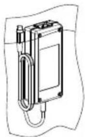
natural_image
Technical line drawing of a mechanical device with a coiled spring and housing (no text or symbols)natural_image
Diagram of a robotic arm with motion arrows indicating movement (no text or symbols)natural_image
Close-up of a hand holding a black USB cable (no visible text or symbols)
natural_image
Hand inserting a black cable into a white electronic device casing (no text or symbols visible)natural_image
Technical line drawing of two open mechanical components with a circle and cross symbol indicating assembly or inspection (no text or labels present)natural_image
Technical line drawing of a printer or printer with an open lid and paper roll, showing internal components and a circular arrow indicating motion (no text or symbols present)natural_image
Line drawing of an open industrial machine with a cross symbol indicating cancellation or disassembly (no text or labels present)natural_image
Technical line drawing of an open industrial machine with a cross symbol indicating cancellation (no text or labels present)natural_image
Pure geometric shapes including circles, rectangles, and crosses without any text or symbolsnatural_image
Two abstract circular patterns with a circle and an X symbol, no text or labels present.natural_image
Hand inserting a white paper into a green printer (no text or symbols visible)<
<
<
natural_image
Hand inserting a printer into a white paper airplane on a green background (no text or symbols visible)<
<
<
natural_image
Close-up of a white plastic panel with black insulation and black cladding, against a green background (no text or symbols visible)
natural_image
Close-up of hands installing or adjusting a device into a white plastic container (no text or symbols visible)flowchart
graph TD
    A["Test Print"] --> B["End"]
    B --> C["Sample Print"]
    C --> D["Data Analysis"]
    D --> E["Cleaning"]
    E --> F["Sensor Adjustment"]
    F --> G["Setup"]
    G --> H["Test Print"]
    H --> I["Selection Item"]
    J["Special Mode"] --> K["Usage"]
    L["Item Selection"] --> M["Please push the feed switch short."]
    N["Item Decision"] --> O["Please push the feed switch long."]
    P["Paper feed direction"] --> Q
flowchart
graph TD
    A["Print Density ↑"] --> B["Print Color ↑"]
    B --> C["NV Graphics Memory ↑"]
    C --> D["User NV Memory"]
    D --> E["Return to Top Menu"]
    E --> F["Return to Up"]
    F --> G["Low Power"]
    G --> H["Max Speed"]
    H --> I["BK Density"]
    I --> J["Print Density"]
    J --> K["Print Color"]
    K --> L["NV Graphics Memory"]
    L --> M["User NV Memory"]
    M --> N["Selection Item"]
other
| Selection Item | Percentage (%) | |---|---| | 100% | ↑ | | 95% | ↑ | | 90% | ↑ | | 85% | ↑ | | 80% | ↑ | | 75% | ↑ | | 70% (Lightest) | ↑ | | 130% (Darkest) | 130% (Darkest) | | 125% | 125% | | 120% | 120% | | 115% | 115% | | 110% | 110% | | 105% | 105% | | 100% | 100% | | 95% | 95% | | 90% | 90% | | 85% | 85% | | 80% | 80% | | 75% | 75% | | 70% (Lightest) | 70% (Lightest) | Selection Item: Paper feed directionflowchart
graph TD
    A["Return to Top Menu"] --> B["Return to Top Menu\nOthers"]
    B --> C["Serial Condition"]
    C --> D["Customize Value"]
    D --> E["Memory Switch"]
    E --> F["Paper Setting"]
    F --> G["Selection Item"]
    G --> H["Return to Up"]
flowchart
graph TD
    A["Test Print"] --> B["End"]
    B --> C["Sample Print"]
    C --> D["Data Analysis"]
    D --> E["Cleaning"]
    E --> F["Sensor Adjustment"]
    F --> G["Setup"]
    G --> H["Test Print"]
    H --> I["Selection Item"]
    I --> J["Special Mode"]
    J --> K["Usage"]
    K --> L["Item Selection"]
    L --> M["Please push the feed switch short."]
    L --> N["Item Decision"]
    N --> O["Please push the feed switch long."]
    P["Paper feed direction"] --> Q
flowchart
graph TD
    A["Return to Up"] --> B["Return to Top Menu"]
    B --> C["Return to Up"]
    C --> D["Sensor Auto Adjust"]
    D --> E["Mark Feed with Cut"]
    E --> F["Feed at Power On"]
    F --> G["Layout Er Recovery"]
    G --> H["Layout Er Process"]
    H --> I["TearOff Adjustment"]
    I --> J["Base Adjustment"]
    J --> K["Paper Width"]
    K --> L["Paper Detection"]
    L --> M["Selection Item"]
    M --> N["9th (High Speed)"]
    style A fill:#f9f,stroke:#333
    style N fill:#ccf,stroke:#333
flowchart
graph TD
    A["Return to Top Menu"] --> B["Return to Top Menu"]
    B --> C["Others"]
    C --> D["Serial Condition"]
    D --> E["Customize Value"]
    E --> F["Memory Switch"]
    F --> G["Paper Setting"]
    G --> H["Selection Item"]
    H --> I["Return to Up"]
    style A fill:#f9f,stroke:#333
    style I fill:#f9f,stroke:#333
    note right of A Paper feed direction
flowchart
graph TD
    A["Test Print"] --> B["End"]
    B --> C["Sample Print"]
    C --> D["Data Analysis"]
    D --> E["Cleaning"]
    E --> F["Sensor Adjustment"]
    F --> G["Setup"]
    G --> H["Test Print"]
    H --> I["Selection Item"]
    I --> J["Special Mode"]
    J --> K["Usage"]
    K --> L["Item Selection"]
    L --> M["Please push the feed switch short."]
    L --> N["Item Decision"]
    N --> O["Please push the feed switch long."]
    P["Paper feed direction"] --> Q
flowchart
graph TD
    A["User NV Memory"] --> B["Return to Top Menu"]
    B --> C["Return to Up"]
    C --> D["Low Power"]
    D --> E["Max Speed"]
    E --> F["BK Density"]
    F --> G["Print Density"]
    G --> H["Print Color"]
    H --> I["NV Graphics Memory"]
    I --> J["User NV Memory"]
    J --> K["Selection Item"]
    K --> L["Customize Value"]
    L --> M["Paper feed direction"]
flowchart
graph TD
    A["Test Print"] --> B["End"]
    B --> C["Sample Print"]
    C --> D["Data Analysis"]
    D --> E["Cleaning"]
    E --> F["Sensor Adjustment"]
    F --> G["Setup"]
    G --> H["Test Print"]
    H --> I["Selection Item"]
    J["Special Mode"] --> K["Usage"]
    K --> L["Item Selection"]
    L --> M["Please push the feed switch short."]
    L --> N["Item Decision"]
    N --> O["Please push the feed switch long."]
    P["Paper feed direction"] --> Q
flowchart
graph TD
    A["Setup ↑"] --> B["Test Print"]
    B --> C["End\nSample Print\nData Analysis\nCleaning\nSensor Adjustment\nSetup\nTest Print\nSelection Item"]
    C --> D["Paper feed direction"]
flowchart
graph TD
    A["Enable"] --> B["Disable"]
    A --> C["Enable"]
    D["Selection Item"] --> E["Feed at Power On"]
    F["Paper feed direction"] --> G["Downward arrow"]
flowchart
graph TD
    A["Feed at Power On"] --> B["Selection Item"]
    C["Enable"] --> D["Disable"]
    E["Enable"] --> F["Disable"]
    G["Enable"] --> H["Disable"]
    I["Disable"] --> J["--> Paper feed direction"]
flowchart
graph TD
    A["Return to Top Menu"] --> B["Sensor Auto Adjust"]
    B --> C["Mark Feed with Cut"]
    C --> D["Feed at Power On"]
    D --> E["Layout Er Recovery"]
    E --> F["Layout Er Process"]
    F --> G["TearOff Adjustment"]
    G --> H["Base Adjustment"]
    H --> I["Paper Width"]
    I --> J["Paper Detection"]
    J --> K["Selection Item"]
    K --> L["Disable"]
flowchart
graph TD
    A["Test Print"] --> B["End"]
    B --> C["Sample Print"]
    C --> D["Data Analysis"]
    D --> E["Cleaning"]
    E --> F["Sensor Adjustment"]
    F --> G["Setup"]
    G --> H["Test Print"]
    H --> I["Selection Item"]
    J["Special Mode"] --> K["Usage"]
    L["Item Selection"] --> M["Please push the feed switch short."]
    N["Item Decision"] --> O["Please push the feed switch long."]
    P["Paper feed direction"] --> Q
flowchart
graph TD
    A["Setup ↑"] --> B["Test Print"]
    B --> C["End Sample Print\nData Analysis\nCleaning\nSensor Adjustment\nSetup\nTest Print\nSelection Item"]
    C --> D["Paper feed direction"]
flowchart
graph TD
    A["Test Print"] --> B["End"]
    B --> C["Sample Print"]
    C --> D["Data Analysis"]
    D --> E["Cleaning"]
    E --> F["Sensor Adjustment"]
    F --> G["Setup"]
    G --> H["Test Print"]
    H --> I["Selection Item"]
    J["Special Mode"] --> K["Usage"]
    K --> L(Item Selection]
    L --> M["Please push the feed switch short."]
    L --> N(Item Decision]
    N --> O["Please push the feed switch long."]
    P["Paper feed direction"] --> Q
flowchart
graph TD
    A["Setup ↑"] --> B["Test Print"]
    B --> C["End Sample Print Data Analysis Cleaning Sensor Adjustment Setup Test Print Selection Item"]
    C --> D["Paper feed direction ↓"]
flowchart
graph TD
    A["Setup"] --> B["Paper Setting"]
    B --> C["Return to Top Menu"]
    C --> D["Paper feed direction"]
    E["Others ↑"] --> F["Serial Condition ↑"]
    F --> G["Customize Value ↑"]
    G --> H["Memory Switch ↑"]
    H --> I["Paper Setting Selection Item"]
flowchart
graph TD
    A["Return to Top Menu"] --> B["Return to Top Menu"]
    B --> C["Others"]
    C --> D["Serial Condition"]
    D --> E["Customize Value"]
    E --> F["Memory Switch"]
    F --> G["Paper Setting"]
    G --> H["Selection Item"]
    H --> I["Return to Up"]
    style A fill:#f9f,stroke:#333
    style I fill:#f9f,stroke:#333
    note right of A Paper feed direction
flowchart
graph TD
    A["Test Print"] --> B["End"]
    B --> C["Sample Print"]
    C --> D["Data Analysis"]
    D --> E["Cleaning"]
    E --> F["Sensor Adjustment"]
    F --> G["Setup"]
    G --> H["Test Print"]
    H --> I["Selection Item"]
    J["Special Mode"] --> K["Usage"]
    K --> L["Item Selection"]
    L --> M["Please push the feed switch short."]
    L --> N["Item Decision"]
    N --> O["Please push the feed switch long."]
    P["Paper feed direction"] --> Q
flowchart
graph TD
    A["Paper Width ↑"] --> B["Return to Top Menu"]
    B --> C["Return to Up"]
    C --> D["Sensor Auto Adjust"]
    D --> E["Mark Feed with Cut"]
    E --> F["Feed at Power On"]
    F --> G["Layout Er Recovery"]
    G --> H["Layout Er Process"]
    H --> I["TearOff Adjustment"]
    I --> J["Base Adjustment"]
    J --> K["Paper Width"]
    K --> L["Paper Detection"]
    L --> M["Selection Item"]
    N["Paper feed direction ↓"] --> A
flowchart
graph TD
    A["Test Print"] --> B["End"]
    B --> C["Sample Print"]
    C --> D["Data Analysis"]
    D --> E["Cleaning"]
    E --> F["Sensor Adjustment"]
    F --> G["Setup"]
    G --> H["Test Print"]
    H --> I["Selection Item"]
    J["Special Mode"] --> K["Usage"]
    K --> L(Item Selection]
    L --> M["Please push the feed switch short."]
    L --> N(Item Decision]
    L --> O["Please push the feed switch long."]
    P["Paper feed direction"] --> Q
flowchart
graph TD
    A["Setup ↑"] --> B["Test Print"]
    B --> C["End\nSample Print\nData Analysis\nCleaning\nSensor Adjustment\nSetup\nTest Print\nSelection Item"]
    C --> D["Paper feed direction"]
Paper feed direction
flowchart
graph TD
    A["Disable"] --> B["Enable"]
    B --> C["Selection Item"]
    C --> D["Batch (OTHER IF)"]
    E["Paper feed direction"] --> F["End"]
flowchart
graph TD
    A["Return to Top Menu"] --> B["Return to Top Menu"]
    B --> C["Others"]
    C --> D["Serial Condition"]
    D --> E["Customize Value"]
    E --> F["Memory Switch"]
    F --> G["Paper Setting"]
    G --> H["Selection Item"]
    H --> I["Return to Up"]
    style A fill:#f9f,stroke:#333
    style I fill:#f9f,stroke:#333
    note right of A Paper feed direction
flowchart
graph TD
    A["Test Print"] --> B["End"]
    B --> C["Sample Print"]
    C --> D["Data Analysis"]
    D --> E["Cleaning"]
    E --> F["Sensor Adjustment"]
    F --> G["Setup"]
    G --> H["Test Print"]
    H --> I["Selection Item"]
    J["Special Mode"] --> K["Usage"]
    L["Item Selection"] --> M["Please push the feed switch short."]
    N["Item Decision"] --> O["Please push the feed switch long."]
    P["Paper feed direction"] --> Q
flowchart
graph TD
    A["Adjustment"] --> B["End"]
    B --> C["Adjustment Print"]
    C --> D["Adjustment"]
    D --> E["Selection Item"]
    E --> F["Sensor Adjustment ↑"]
    F --> G["Setup ↑"]
    G --> H["Test Print"]
    style A fill:#f9f,stroke:#333
    style H fill:#f9f,stroke:#333
flowchart
graph TD
    A["Adjustment Print"] --> B["Adjustment"]
    B --> C["End"]
    C --> D["Adjustment Print"]
    C --> E["Adjustment"]
    E --> F["Selection Item"]
    G["Paper feed direction"] --> H
flowchart
graph TD
    A["Test Print"] --> B["End Sample Print"]
    B --> C["Data Analysis"]
    C --> D["Cleaning"]
    D --> E["Sensor Adjustment"]
    E --> F["Setup"]
    F --> G["Test Print Selection Item"]
    G --> H["Special Mode"]
    H --> I["Usage"]
    I --> J["Item Selection"]
    J --> K["Please push the feed switch short."]
    J --> L["Item Decision"]
    L --> M["Please push the feed switch long."]
    N["Paper feed direction"] --> A
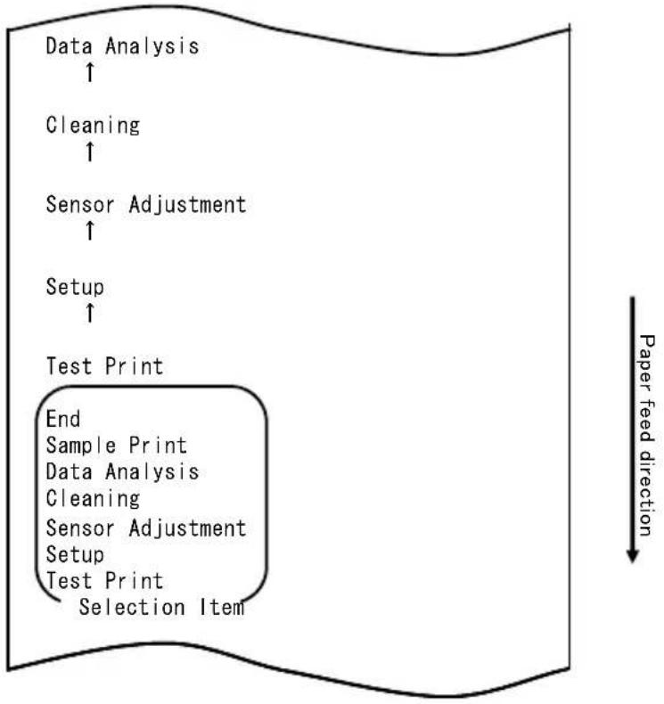
flowchart
graph TD
    A["Data Analysis ↑"] --> B["Cleaning ↑"]
    B --> C["Sensor Adjustment ↑"]
    C --> D["Setup ↑"]
    D --> E["Test Print"]
    E --> F["End Sample Print"]
    E --> G["Data Analysis Cleaning"]
    E --> H["Sensor Adjustment Setup"]
    E --> I["Test Print Selection Item"]
    style E fill:#f9f,stroke:#333
    note right of E Paper feed direction
flowchart
graph TD
    A["Hex Dump"] --> B["End"]
    B --> C["Command Trace"]
    C --> D["Hex Dump"]
    D --> E["Selection Item"]
    E --> F["Data Analysis"]
    G["Paper feed direction"] --> H["Downward arrow"]
1. Mode HEX DUMP (vidage hexadécimal)
flowchart
graph TD
    A["Test Print"] --> B["End"]
    B --> C["Sample Print"]
    C --> D["Data Analysis"]
    D --> E["Cleaning"]
    E --> F["Sensor Adjustment"]
    F --> G["Setup"]
    G --> H["Test Print"]
    H --> I["Selection Item"]
    J["Special Mode"] --> K["Usage"]
    L["Item Selection"] --> M["Please push the feed switch short."]
    N["Item Decision"] --> O["Please push the feed switch long."]
    P["Paper feed direction"] --> Q
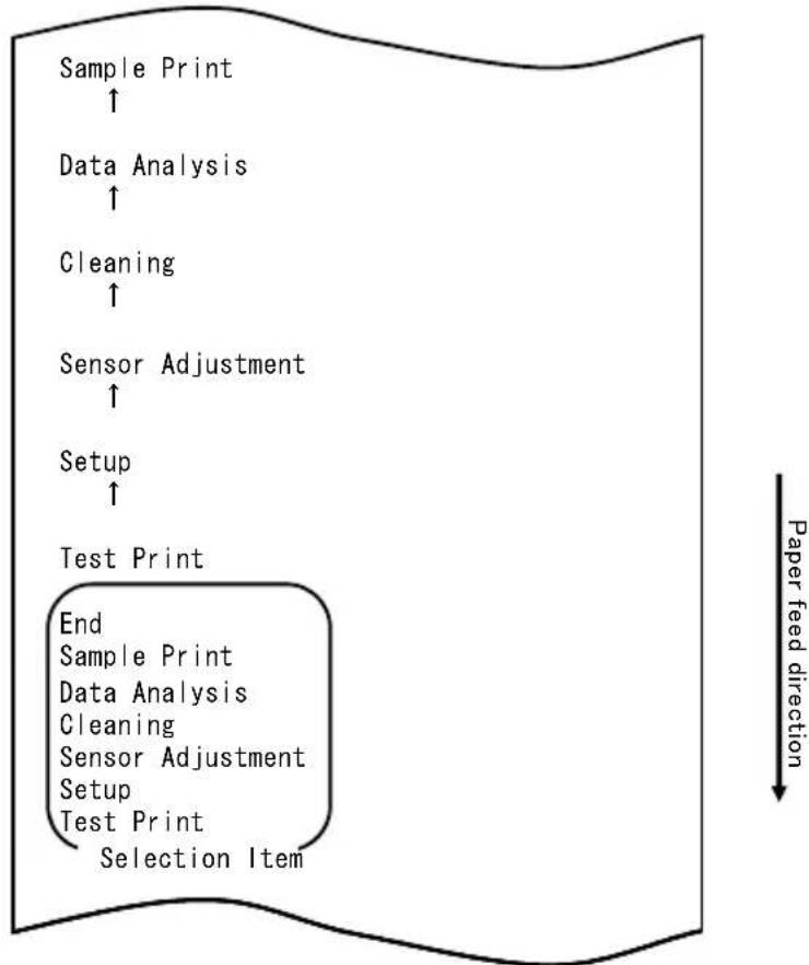
flowchart
graph TD
    A["Sample Print ↑"] --> B["Data Analysis ↑"]
    B --> C["Cleaning ↑"]
    C --> D["Sensor Adjustment ↑"]
    D --> E["Setup ↑"]
    E --> F["Test Print"]
    F --> G["End Sample Print"]
    G --> H["Data Analysis Cleaning"]
    H --> I["Sensor Adjustment Setup"]
    I --> J["Test Print Selection Item"]
    style F fill:#f9f,stroke:#333
    note right of F Paper feed direction
| name | Pizza |
| Ingredient | Wheat, Yeast, Olives, Olive gif, Tomato, Mczzarella cheese, Basil Oregano, Onions, Capers, Sausage, Chile Peppers, Mushrooms Anchovies |
| Expiration | XX-XX-20xx |
| Manufacturer | OKI Food Ltd. |
Modèle « LABEL3 »

Modèle « LABEL4 »

Modèle « LABEL5 »
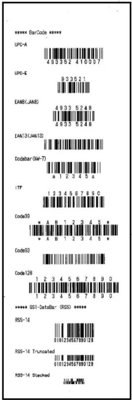
natural_image
Simple downward-pointing arrow shape with no text or symbols
natural_image
Simple downward-pointing arrow shape with no text or symbols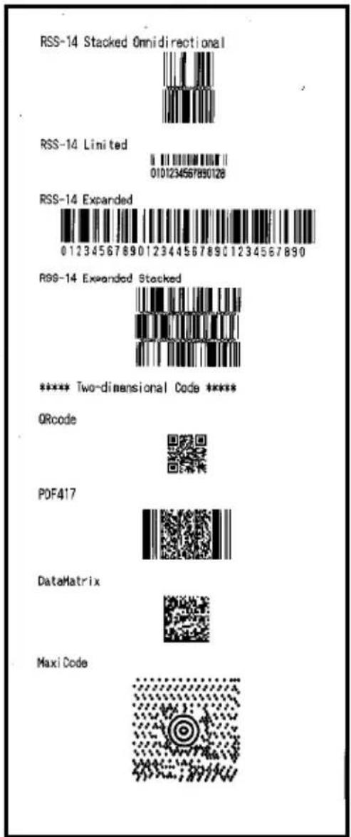
natural_image
Hand placing a plastic bag onto a white plastic container with black contents (no text or symbols visible)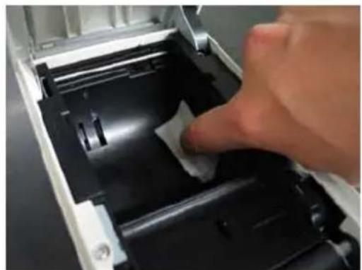
natural_image
Close-up of a hand pressing down on a mechanical component with a white paper clip (no visible text or symbols)flowchart
graph TD
    A["Test Print"] --> B["End"]
    B --> C["Sample Print"]
    C --> D["Data Analysis"]
    D --> E["Cleaning"]
    E --> F["Sensor Adjustment"]
    F --> G["Setup"]
    G --> H["Test Print"]
    H --> I["Selection Item"]
    I --> J["Special Mode"]
    J --> K["Usage"]
    K --> L["Item Selection"]
    L --> M["Please push the feed switch short."]
    L --> N["Item Decision"]
    N --> O["Please push the feed switch long."]
    P["Paper feed direction"] --> Q
flowchart
graph TD
    A["Cleaning ↑"] --> B["Sensor Adjustment ↑"]
    B --> C["Setup ↑"]
    C --> D["Test Print"]
    D --> E["End Sample Print Data Analysis Cleaning Sensor Adjustment Setup Test Print Selection Item"]
    E --> F["Special Mode"]
    F --> G["Usage"]
    G --> H["Item Selection Please push the feed switch short. Item Decision Please push the feed switch long."]
    H --> I["Paper feed direction ↓"]
natural_image
Close-up of a hand inserting a white plastic bag into an open electronic device casing (no text or symbols visible)Tête thermique
natural_image
Two screwdriver tools laid out on a dark surface, one with a blue handle and the other with a white handle (no text or symbols visible)
flowchart
graph TD
    A["Test Print"] --> B["End"]
    B --> C["Sample Print"]
    C --> D["Data Analysis"]
    D --> E["Cleaning"]
    E --> F["Sensor Adjustment"]
    F --> G["Setup"]
    G --> H["Test Print"]
    H --> I["Selection Item"]
    I --> J["Special Mode"]
    J --> K["Usage"]
    K --> L["Item Selection"]
    L --> M["Please push the feed switch short."]
    L --> N["Item Decision"]
    N --> O["Please push the feed switch long."]
    P["Paper feed direction"] --> Q
flowchart
graph TD
    A["Cleaning ↑"] --> B["Sensor Adjustment ↑"]
    B --> C["Setup ↑"]
    C --> D["Test Print"]
    D --> E["End Sample Print Data Analysis Cleaning Sensor Adjustment Setup Test Print Selection Item"]
    E --> F["Special Mode"]
    F --> G["Usage"]
    G --> H["Item Selection Please push the feed switch short. Item Decision Please push the feed switch long."]
natural_image
Pure electrical connector pinout diagram without any text or symbolsCôté de connexion
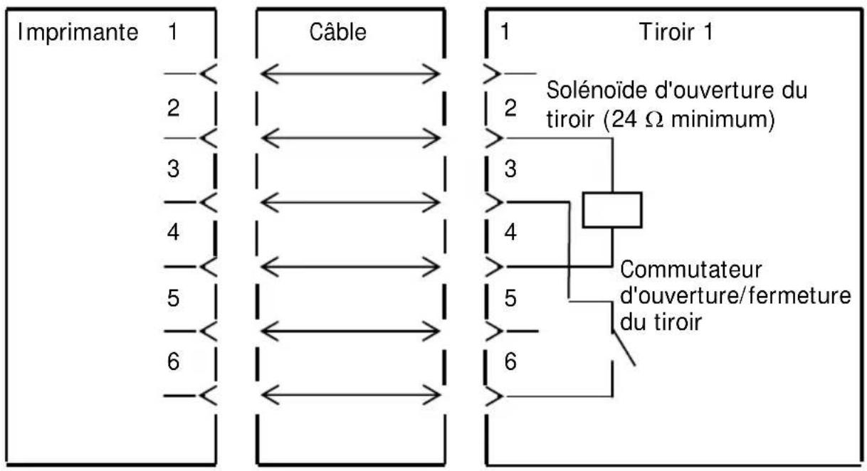
natural_image
Line drawing of a rectangular electronic device with lid and ventilation slots (no text or symbols)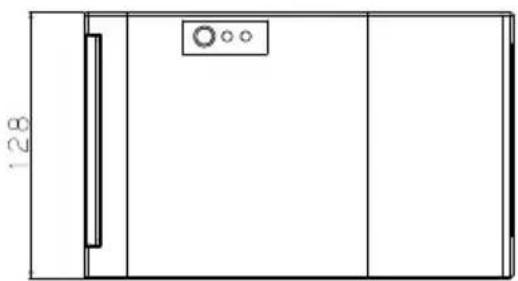
natural_image
Simple line drawing of a rectangular room with a door, window, and circular elements (no text or symbols)
Guide-papier ouvert
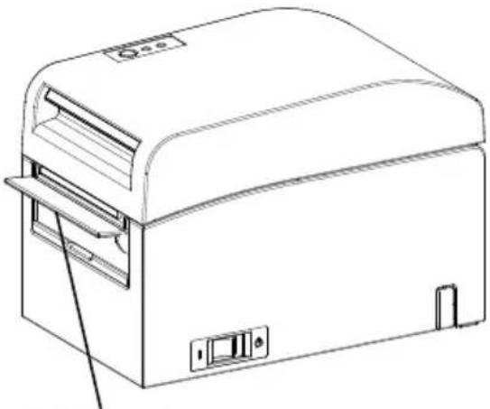
natural_image
Line drawing of a portable electronic device with ventilation slots and control panel (no text or symbols)Guide-papier
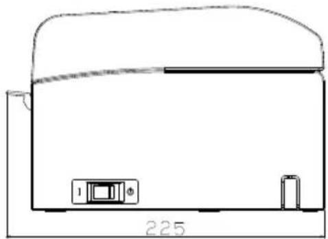
natural_image
Simple line drawing of a device with a base, top, and bottom components (no text or symbols)natural_image
Line drawing of a door handle with a hatched panel and control buttons (no text or symbols)natural_image
Technical line drawing of a cylindrical mechanical component with mounting holes and internal brackets (no text or symbols)natural_image
Technical line drawing of a mechanical component with multiple slots and a central hub (no text or symbols)natural_image
Line drawing of a portable electronic device with a lid and base (no text or symbols)natural_image
Technical line drawing of a mechanical device with internal components and mounting bracket (no text or symbols)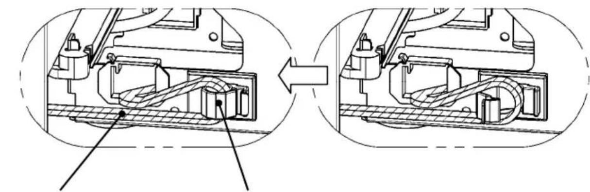
natural_image
Technical diagram showing mechanical assembly before and after division, with no visible text or symbolsnatural_image
Technical line drawing of a mechanical device with internal components and an upward arrow indicating motion (no text or symbols present)natural_image
Technical line drawing of a mechanical device with internal components and an upward arrow indicating motion (no text or symbols)natural_image
Two abstract circular diagrams with curved lines and a circle, one marked with an 'X' and the other with a circle (no text or symbols)natural_image
Technical line drawing of a mechanical device with no visible text or symbolsOki Systems (UK) Ltd
Blays House
Wick Road
Egham
Surrey
TW20 0HJ
Tel: +44 (0) 1784 274300
Fax: +44 (0) 1784 274301
http://www.oki.co.uk
Oki Systems Ireland Limited
The Square Industrial Complex Tallaght
Dublin 24
Tel: +353 (0) 1 4049590
Fax: +353 (0)1 4049591
http://www.oki.ie
Oki Systems Ireland Limited - Northern Ireland
19 Ferndale Avenue
Glengormley
BT36 5AL
Northern Ireland
Tel: +44 (0) 7767 271447
Fax: +44 (0) 1 404 9520
http://www.oki.ie
Technical Support for all Ireland:
Tel: +353 1 4049570
Fax: +353 1 4049555
E-mail: tech.support@oki.ie
OKI Systems (Czech and Slovak), s.r.o.
Futurama Business Park - Sokolovská 651/136A
186 00 Praha 8
Czech Republic
Tel: +420 224 890158
Fax:+420 22 232 6621
Website: www.oki.cz, www.oki.sk
Albania, Bosnia, Bulgaria, Croatia,
Cyprus, Estonia, Greece, Israel,
Latvia, Lithuania, Macedonia,
Romania, Serbia, Slovenia
CEE Export Group: OKI Systems (Poland) Ltd
ul. Domaniewska 42
02-672 Warsaw
Poland
Tel: +48 (0) 22 448 65 00
Fax: +48 (0) 22 448 65 0
E-mail: tech@oki.com.pl
Platinum Business Park II, 3rd Floor
ul. Domaniewska 42
02-672 Warsaw
Poland
Tel: +48 22 448 65 00
Fax: +48 22 448 65 01
Website: www.oki.com.pl
E-mail: oki@oki.com.pl
Hotline: 0800 120066
E-mail: tech@oki.com.pl
OKI Systems Rus, LLC (Russia)
Sector B, 3rd Floor, Svyatogor-4
Business Center10/4, Letnikovskaya
str.115114, Moscow
Tel: +7 495 276 5060
Fax: +7 495 258 6070
e-mail: info@oki.ru
Website: www.oki.ru
Technical support:
Tel: +7 495 564 8421
e-mail: tech@oki.ru
Raisy Opkinoy Street,8
Building B, 2 ^nd Floor,
Kiev 02002
Ukraine
Tel: +380 44 537 5288
e-mail: event@oki.ua
Website: www.oki.ua
Oki Systems (Belgium)
Medialaan 24
1800 Vilvoorde
Helpdesk: 02-2574620
Fax: 02 2531848
Website: www.oki.be
OKI Systems (Danmark) a·s
Herstedøstervej 27
2620 Albertslund
Danmark
Oki Systems (Norway) AS
Tevlingveien 23
N-1081 Oslo
Tel: +47 (0) 63 89 36 00
Telefax: +47 (0) 63 89 36 01
Website: www.oki.no
Var vänlig kontakta din
Oki Systems (Sweden) AB
Borgafjordsgatan 7
Box 1193
164 26 Kista
Tel. +46 (0) 8 634 37 00
e-mail: info@oki.se
Website: www.oki.se
2000 Bishops Gate Blvd.
http://WWW.OKIPRINTINGSOLUTIONS.COM
http://my.okidata.com
Oki Data Americas Inc.(Canada • Canadá)
4140B Sladeview Crescent Unit 7 & 8
Mississauga, Ontario
Canada L5L 6A1
Tél: 1-905-608-5000
Téléc: 1-905-608-5040
http://WWW.OKIPRINTINGSOLUTIONS.COM
Oki Data Americas Inc.(América Latina (OTRO))
2000 Bishops Gate Blvd.
HTTP://www.okiprintingsolutions.com
Argentina/ Chile/ Paraguay/ Perú/ Uruguay
Oki Data Americas, Inc.
Sucursal Argentina
Ugarte 3610 Piso 4°(1605) Olivos
Buenos Aires, Argentina
TEL: +54 11 5288 7500
Fax: +54 11 5288 7599
Colombia/ Ecuador/ Venezuela/ Centroamérica y Caribe Oki Data Americas, Inc.
Sucursal Colombia
1168/81-82 Lumpini Tower,
27th Floor Rama IV Road
Tungmahamek, Sathorn
Bangkok 10120
Tel: (662) 679 9235
Fax: (662) 679 9243/245
http://www.okisysthai.com
Oki Data(Australia) Pty Ltd.
Level1 67 Epping Road, Macquare Park
NSW 2113, Australia
Tel: +61 2 8071 0000
(Support Tel: 1800 807 472)
Fax: +61 2 8071 0010
http://www.oki.com.au
OKI Data New Zealand
8 Antares Place Rosedale,
Auckland, 0632 New Zealand
Tel: (64) 9 477 0500
Fax: (64) 9 477 0549
http://www.oki.co.nz/
Oki Data(S) P Ltd. Malaysia Rep Office
Suite 21.03, 21st Floor Menara IGB, Mid Valley City,
Lingkaran Syed Pura 59200,
Kuala Lumpur, Malaysia
Tel: (60) 3 2287 1177
Fax: (60) 3 2287 1166
Manuale d'uso
PREFAZIONE
© 2011 Oki Data Corporation
OKI Data Corporation,
4-11-22 Shibaura, Minato-ku,
Tokyo 108-8551,
Giappone
natural_image
Pure geometric diagram with concentric circles and a diagonal line, no text or symbols presentMANUALE
DRIVER STAMPANTE
UTILITY
natural_image
Simple geometric diamond shape with no text or symbolsnatural_image
Simple geometric diamond shape outline with no text or symbols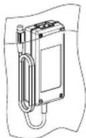
natural_image
Technical line drawing of a mechanical device with a coiled cable and housing (no text or symbols)Trasformatore CA
natural_image
Diagram of a mechanical device with an upward arrow and internal components (no text or symbols)natural_image
Technical line drawing of two open mechanical components with a circular inset showing a circle (no text or symbols)natural_image
Technical line drawing of a printer or scanner device with an open lid and arrow indicating direction (no text or symbols present)natural_image
Technical line drawing of an open industrial machine with a cross symbol indicating failure or invalid (no text or labels present)natural_image
Line drawing of a mechanical device with open lid and internal components, no text or symbols presentnatural_image
Two abstract circular patterns with a circle and an 'X' symbol, no text or labels present.natural_image
Hand inserting a printer into a paper airplane into a green background (no text or symbols visible)<
<
<
natural_image
Hand inserting a printer into a paper airplane into a green background (no text or symbols visible)<
<
<
natural_image
Close-up of a white plastic panel with black insulation and a black clip inserted, against a green background (no text or symbols visible)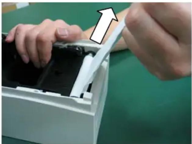
natural_image
Close-up of hands installing or adjusting a device into a white plastic container (no text or symbols visible)flowchart
graph TD
    A["Test Print"] --> B["End"]
    B --> C["Sample Print"]
    C --> D["Data Analysis"]
    D --> E["Cleaning"]
    E --> F["Sensor Adjustment"]
    F --> G["Setup"]
    G --> H["Test Print"]
    H --> I["Selection Item"]
    J["Special Mode"] --> K["Usage"]
    L["Item Selection"] --> M["Please push the feed switch short."]
    N["Item Decision"] --> O["Please push the feed switch long."]
    P["Paper feed direction"] --> Q
Paper feed direction
flowchart
graph TD
    A["Print Density ↑"] --> B["Print Color ↑"]
    B --> C["NV Graphics Memory ↑"]
    C --> D["User NV Memory"]
    D --> E["Return to Top Menu"]
    E --> F["Return to Up"]
    F --> G["Low Power"]
    G --> H["Max Speed"]
    H --> I["BK Density"]
    I --> J["Print Density"]
    J --> K["Print Color"]
    K --> L["NV Graphics Memory"]
    L --> M["User NV Memory"]
    M --> N["Selection Item"]
flowchart
graph TD
    A["Test Print"] --> B["End"]
    B --> C["Sample Print"]
    C --> D["Data Analysis"]
    D --> E["Cleaning"]
    E --> F["Sensor Adjustment"]
    F --> G["Setup"]
    G --> H["Test Print"]
    H --> I["Selection Item"]
    J["Special Mode"] --> K["Usage"]
    L["Item Selection"] --> M["Please push the feed switch short."]
    M --> N["Item Decision"]
    N --> O["Please push the feed switch long."]
    P["Paper feed direction"] --> Q
flowchart
graph TD
    A["Return to Top Menu"] --> B["Return to Top Menu Others"]
    B --> C["Serial Condition"]
    C --> D["Customize Value"]
    D --> E["Memory Switch"]
    E --> F["Paper Setting"]
    F --> G["Selection Item"]
    G --> H["Return to Up"]
    I["Paper feed direction"] --> A
flowchart
graph TD
    A["Paper Detection"] --> B["Return to Top Menu"]
    B --> C["Return to Up"]
    C --> D["Sensor Auto Adjust"]
    D --> E["Mark Feed with Cut"]
    E --> F["Feed at Power On"]
    F --> G["Layout Er Recovery"]
    G --> H["Layout Er Process"]
    H --> I["TearOff Adjustment"]
    I --> J["Base Adjustment"]
    J --> K["Paper Width"]
    K --> L["Paper Detection"]
    L --> M["Selection Item"]
    M --> N["Paper Setting"]
flowchart
graph TD
    A["Feed at Power On ↑"] --> B["Layout Er Recovery ↑"]
    B --> C["Layout Er Process ↑"]
    C --> D["TearOff Adjustment ↑"]
    D --> E["Base Adjustment ↑"]
    E --> F["Paper Width ↑"]
    F --> G["Paper Detection"]
    G --> H["Return to Top Menu Return to Up Sensor Auto Adjust Mark Feed with Cut Feed at Power On Layout Er Recovery Layout Er Process TearOff Adjustment Base Adjustment Paper Width Paper Detection Selection Item"]
    H --> I["Paper feed direction ↓"]
flowchart
graph TD
    A["Disable ↑"] --> B["Enable"]
    B --> C["Disable Enable Selection Item"]
    C --> D["Feed at Power On"]
    E["Paper feed direction"] --> F["-->"]
flowchart
graph TD
    A["Return to Top Menu"] --> B["Return to Top Menu\nOthers"]
    A --> C["Serial Condition"]
    A --> D["Customize Value"]
    A --> E["Memory Switch"]
    A --> F["Paper Setting"]
    A --> G["Selection Item"]
    H["Return to Up"] --> I["Paper feed direction"]
flowchart
graph TD
    A["End"] --> B["Default Set"]
    B --> C["Setup Print"]
    C --> D["Setup"]
    D --> E["End"]
    style D fill:#f9f,stroke:#333
    note right of E "Selection Item"
    note right of F "Paper feed direction"
flowchart
graph TD
    A["Test Print"] --> B["End"]
    B --> C["Sample Print"]
    C --> D["Data Analysis"]
    D --> E["Cleaning"]
    E --> F["Sensor Adjustment"]
    F --> G["Setup"]
    G --> H["Test Print"]
    H --> I["Selection Item"]
    J["Special Mode"] --> K["Usage"]
    L["Item Selection"] --> M["Please push the feed switch short."]
    N["Item Decision"] --> O["Please push the feed switch long."]
    P["Paper feed direction"] --> Q
flowchart
graph TD
    A["Setup ↑"] --> B["Test Print"]
    B --> C["End Sample Print Data Analysis Cleaning Sensor Adjustment Setup Test Print Selection Item"]
    style B fill:#f9f,stroke:#333
    note right of B Paper feed direction
flowchart
graph TD
    A["Return to Top Menu"] --> B["Return to Up"]
    B --> C["Sensor Auto Adjust"]
    C --> D["Mark Feed with Cut"]
    D --> E["Feed at Power On"]
    E --> F["Layout Er Recovery"]
    F --> G["Layout Er Process"]
    G --> H["TearOff Adjustment"]
    H --> I["Base Adjustment"]
    I --> J["Paper Width"]
    J --> K["Paper Detection"]
    K --> L["Selection Item"]
    M["Paper Setting"] --> N["Paper feed direction"]
flowchart
graph TD
    A["Paper Width ↑"] --> B["Return to Top Menu"]
    B --> C["Return to Up"]
    C --> D["Sensor Auto Adjust"]
    D --> E["Mark Feed with Cut"]
    E --> F["Feed at Power On"]
    F --> G["Layout Er Recovery"]
    G --> H["Layout Er Process"]
    H --> I["TearOff Adjustment"]
    I --> J["Base Adjustment"]
    J --> K["Paper Width"]
    K --> L["Paper Detection"]
    L --> M["Selection Item"]
flowchart
graph TD
    A["Test Print"] --> B["End"]
    B --> C["Sample Print"]
    C --> D["Data Analysis"]
    D --> E["Cleaning"]
    E --> F["Sensor Adjustment"]
    F --> G["Setup"]
    G --> H["Test Print"]
    H --> I["Selection Item"]
    J["Special Mode"] --> K["Usage"]
    L["Item Selection"] --> M["Please push the feed switch short."]
    N["Item Decision"] --> O["Please push the feed switch long."]
    P["Paper feed direction"] --> Q
Paper feed direction
flowchart
graph TD
    A["Disable"] --> B["Enable"]
    B --> C["Selection Item"]
    C --> D["Batch (OTHER IF)"]
    style A fill:#f9f,stroke:#333
    style D fill:#ccf,stroke:#333
    note right of D Paper feed direction
flowchart
graph TD
    A["Enable ↑"] --> B["Disable"]
    B --> C["Disable Enable Selection Item"]
    C --> D["Batch (OTHER IF)"]
    E["Paper feed direction ↓"] --> F["End"]
flowchart
graph TD
    A["Test Print"] --> B["End"]
    B --> C["Sample Print"]
    C --> D["Data Analysis"]
    D --> E["Cleaning"]
    E --> F["Sensor Adjustment"]
    F --> G["Setup"]
    G --> H["Test Print"]
    H --> I["Selection Item"]
    J["Special Mode"] --> K["Usage"]
    L["Item Selection"] --> M["Please push the feed switch short."]
    N["Item Decision"] --> O["Please push the feed switch long."]
    P["Paper feed direction"] --> Q
flowchart
graph TD
    A["Adjustment"] --> B["End"]
    B --> C["Adjustment Print"]
    C --> D["Adjustment"]
    D --> E["Selection Item"]
    E --> F["Sensor Adjustment ↑"]
    F --> G["Setup ↑"]
    G --> H["Test Print"]
    style A fill:#f9f,stroke:#333
    style H fill:#f9f,stroke:#333
flowchart
graph TD
    A["Adjustment Print"] --> B["End Adjustment Print Adjustment"]
    B --> C["Selection Item"]
    D["Paper feed direction"] --> E["Downward arrow"]
flowchart
graph TD
    A["Test Print"] --> B["End"]
    B --> C["Sample Print"]
    C --> D["Data Analysis"]
    D --> E["Cleaning"]
    E --> F["Sensor Adjustment"]
    F --> G["Setup"]
    G --> H["Test Print"]
    H --> I["Selection Item"]
    I --> J["Special Mode"]
    J --> K["Usage"]
    K --> L["Item Selection"]
    L --> M["Please push the feed switch short."]
    L --> N["Item Decision"]
    N --> O["Please push the feed switch long."]
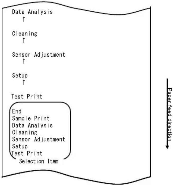
flowchart
graph TD
    A["Data Analysis ↑"] --> B["Cleaning ↑"]
    B --> C["Sensor Adjustment ↑"]
    C --> D["Setup ↑"]
    D --> E["Test Print"]
    E --> F["End Sample Print Data Analysis Cleaning Sensor Adjustment Setup Test Print Selection Item"]
    style E fill:#f9f,stroke:#333
flowchart
graph TD
    A["Hex Dump"] --> B["End"]
    B --> C["Command Trace"]
    C --> D["Hex Dump"]
    D --> E["Selection Item"]
    E --> F["Data Analysis"]
    G["Paper feed direction"] --> H
1. Modo HEX DUMP
flowchart
graph TD
    A["Test Print"] --> B["End"]
    B --> C["Sample Print"]
    C --> D["Data Analysis"]
    D --> E["Cleaning"]
    E --> F["Sensor Adjustment"]
    F --> G["Setup"]
    G --> H["Test Print"]
    H --> I["Selection Item"]
    I --> J["Special Mode"]
    J --> K["Usage"]
    K --> L["Item Selection"]
    L --> M["Please push the feed switch short."]
    L --> N["Item Decision"]
    N --> O["Please push the feed switch long."]

flowchart
graph TD
    A["Sample Print ↑"] --> B["Data Analysis ↑"]
    B --> C["Cleaning ↑"]
    C --> D["Sensor Adjustment ↑"]
    D --> E["Setup ↑"]
    E --> F["Test Print"]
    F --> G["End Sample Print Data Analysis Cleaning Sensor Adjustment Setup Test Print Selection Item"]
    G --> H["Paper feed direction ↓"]
| name | Pizza |
| Ingredient | Wheat, Yeast, Olives, Olive oil, Tonato, Mozzarella cheese, Basil Oregano, Onions, Capers, Sausage, Chile Peppers, Mushrooms Anchovies |
| Expiration | XX-XX-20xx |
| Manufacturer | OKI Food Ltd. |
Motivo "LABEL3"

Motivo "LABEL4"

Motivo "LABEL5"
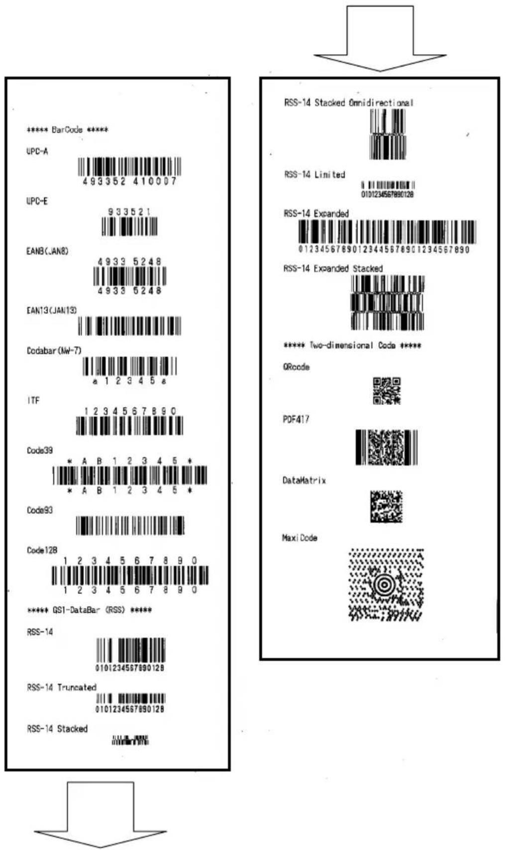
natural_image
Hand inserting a plastic into a white plastic container with black internal components (no text or symbols visible)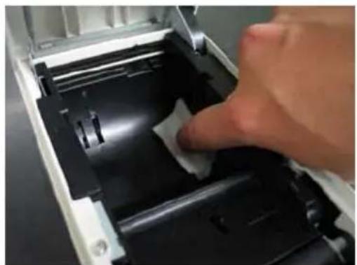
natural_image
Close-up of a hand pressing down on a mechanical component with a white plastic clip (no visible text or symbols)Paper feed direction
flowchart
graph TD
    A["Cleaning ↑"] --> B["Sensor Adjustment ↑"]
    B --> C["Setup ↑"]
    C --> D["Test Print"]
    D --> E["End Sample Print Data Analysis Cleaning Sensor Adjustment Setup Test Print Selection Item"]
    E --> F["Special Mode"]
    F --> G["Usage"]
    G --> H["Item Selection Please push the feed switch short. Item Decision Please push the feed switch long."]
natural_image
Close-up of a hand inserting a white paper into a device casing, with no visible text or symbols.Testina termica
natural_image
Two laboratory tools on a dark surface: a metal screwdriver and a digital thermometer (no visible text or symbols)
Paper feed direction
flowchart
graph TD
    A["Cleaning ↑"] --> B["Sensor Adjustment ↑"]
    B --> C["Setup ↑"]
    C --> D["Test Print"]
    D --> E["End Sample Print Data Analysis Cleaning Sensor Adjustment Setup Test Print Selection Item"]
    E --> F["Special Mode"]
    F --> G["Usage"]
    G --> H["Item Selection Please push the feed switch short. Item Decision Please push the feed switch long."]
natural_image
Pure electrical circuit lines without any symbolsnatural_image
Line drawing of a rectangular electronic device with lid and ventilation slots (no text or symbols)
natural_image
Pure technical line drawing of a door or cabinet with no text, numbers, or symbols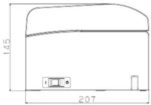
natural_image
Line drawing of a portable electronic device with ventilation slots and control buttons (no text or symbols)
natural_image
Technical line drawing of a mechanical component with dimension标注 (no text or symbols)Guida per la carta
natural_image
Line drawing of a door handle with a hatched panel and buttons (no text or symbols)natural_image
Technical line drawing of a cylindrical mechanical component with mounting holes and internal brackets (no text or symbols)natural_image
Technical line drawing of a mechanical component with multiple slots and a central hub (no text or symbols)natural_image
Technical line drawing of a mechanical device with internal components and mounting bracket (no text or symbols)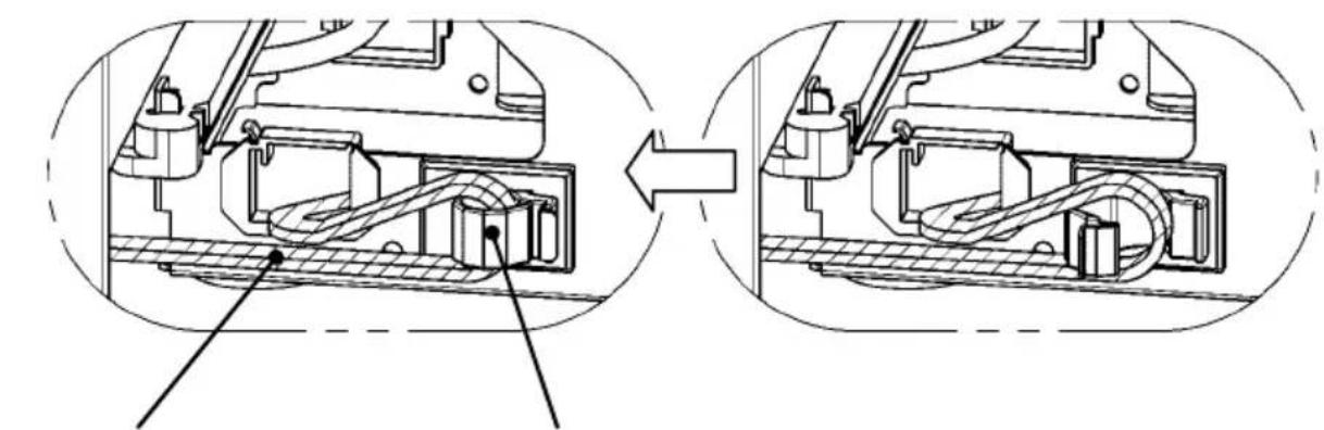
natural_image
Technical diagram showing internal mechanical assembly before and after assembly (no text or labels)natural_image
Technical line drawing of a mechanical device with internal components and an upward arrow indicating motion (no text or symbols present)natural_image
Technical line drawing of a mechanical device with internal components and an arrow indicating motion (no text or symbols)natural_image
Two abstract circular patterns with a circle and an 'X' symbol, no text or labels present.natural_image
Technical line drawing of a mechanical device with no visible text or symbolsOki Systems (UK) Ltd
Blays House
Wick Road
Egham
Surrey
TW20 0HJ
Tel: +44 (0) 1784 274300
Fax: +44 (0) 1784 274301
http://www.oki.co.uk
Oki Systems Ireland Limited
The Square Industrial Complex Tallaght
Dublin 24
Tel: +353 (0) 1 4049590
Fax: +353 (0)1 4049591
http://www.oki.ie
Oki Systems Ireland Limited - Northern Ireland
19 Ferndale Avenue
Glengormley
BT36 5AL
Northern Ireland
Tel: +44 (0) 7767 271447
Fax: +44 (0) 1 404 9520
http://www.oki.ie
Technical Support for all Ireland:
Tel: +353 1 4049570
Fax: +353 1 4049555
E-mail: tech.support@oki.ie
OKI Systems (Czech and Slovak), s.r.o.
Futurama Business Park -
Sokolovská 651/136A
186 00 Praha 8
Czech Republic
Tel: +420 224 890158
Fax:+420 22 232 6621
Website: www.oki.cz, www.oki.sk
Albania, Bosnia, Bulgaria, Croatia,
Cyprus, Estonia, Greece, Israel,
Latvia, Lithuania, Macedonia,
Romania, Serbia, Slovenia
CEE Export Group: OKI Systems (Poland) Ltd
ul. Domaniewska 42
02-672 Warsaw
Poland
Tel: +48 (0) 22 448 65 00
Fax: +48 (0) 22 448 65 0
E-mail: tech@oki.com.pl
Platinum Business Park II, 3rd Floor
ul. Domaniewska 42
02-672 Warsaw
Poland
Tel: +48 22 448 65 00
Fax: +48 22 448 65 01
Website: www.oki.com.pl
E-mail: oki@oki.com.pl
Hotline: 0800 120066
E-mail: tech@oki.com.pl
OKI Systems Rus, LLC (Russia)
Sector B, 3rd Floor, Svyatogor-4
Business Center10/4, Letnikovskaya
str.115114, Moscow
Tel: +7 495 276 5060
Fax: +7 495 258 6070
e-mail: info@oki.ru
Website: www.oki.ru
Technical support:
Tel: +7 495 564 8421
e-mail: tech@oki.ru
Raisy Opkinoy Street,8
Building B, 2 ^nd Floor,
Kiev 02002
Ukraine
Tel: +380 44 537 5288
e-mail: event@oki.ua
Website: www.oki.ua
Oki Systems (Belgium)
Medialaan 24
1800 Vilvoorde
Helpdesk: 02-2574620
Fax: 02 2531848
Website: www.oki.be
OKI Systems (Danmark) a·s
Herstedøstervej 27
2620 Albertslund
Danmark
Oki Systems (Norway) AS
Tevlingveien 23
N-1081 Oslo
Tel: +47 (0) 63 89 36 00
Telefax: +47 (0) 63 89 36 01
Website: www.oki.no
Var vänlig kontakta din
Oki Systems (Sweden) AB
Borgafjordsgatan 7
Box 1193
164 26 Kista
Tel. +46 (0) 8 634 37 00
e-mail: info@oki.se
Website: www.oki.se
2000 Bishops Gate Blvd.
http://WWW.OKIPRINTINGSOLUTIONS.COM
http://my.okidata.com
Oki Data Americas Inc.(Canada • Canadá)
4140B Sladeview Crescent Unit 7 & 8
Mississauga, Ontario
Canada L5L 6A1
Tél: 1-905-608-5000
Téléc: 1-905-608-5040
http://WWW.OKIPRINTINGSOLUTIONS.COM
Oki Data Americas Inc.(América Latina (OTRO))
2000 Bishops Gate Blvd.
HTTP://www.okiprintingsolutions.com
Argentina/ Chile/ Paraguay/ Perú/ Uruguay
Oki Data Americas, Inc.
Sucursal Argentina
Ugarte 3610 Piso 4°(1605) Olivos
Buenos Aires, Argentina
TEL: +54 11 5288 7500
Fax: +54 11 5288 7599
Colombia/ Ecuador/ Venezuela/ Centroamérica y Caribe Oki Data Americas, Inc.
Sucursal Colombia
1168/81-82 Lumpini Tower,
27th Floor Rama IV Road
Tungmahamek, Sathorn
Bangkok 10120
Tel: (662) 679 9235
Fax: (662) 679 9243/245
http://www.okisysthai.com
Oki Data(Australia) Pty Ltd.
Level1 67 Epping Road, Macquare Park
NSW 2113, Australia
Tel: +61 2 8071 0000
(Support Tel: 1800 807 472)
Fax: +61 2 8071 0010
http://www.oki.com.au
OKI Data New Zealand
8 Antares Place Rosedale,
Auckland, 0632 New Zealand
Tel: (64) 9 477 0500
Fax: (64) 9 477 0549
http://www.oki.co.nz/
Oki Data(S) P Ltd. Malaysia Rep Office
Suite 21.03, 21st Floor Menara IGB, Mid Valley City,
Lingkaran Syed Pura 59200,
Kuala Lumpur, Malaysia
Tel: (60) 3 2287 1177
Fax: (60) 3 2287 1166
Benutzerhandbuch
VORWORT
© 2011 Oki Data Corporation
OKI Data Corporation,
4-11-22 Shibaura, Minato-ku,
Tokyo 108-8551,
Japan
natural_image
Simple geometric diagram with concentric circles and a diagonal line inside a diamond shape (no text or symbols)HANDBUCH
DRUCKERTREIBER
DIENSTPROGRAMM
natural_image
Simple geometric diamond shape outline with no text or symbolsnatural_image
Simple geometric diamond shape with no text or symbols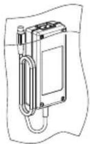
natural_image
Technical line drawing of a mechanical device with no visible text or symbolsNetzteil Netzkabel

2. Netzteil
2-1. Netzteil
natural_image
Diagram of a vehicle interior with a person standing on top, showing engine and exhaust components (no text or symbols)natural_image
Close-up of a hand holding a black USB cable (no text or symbols visible)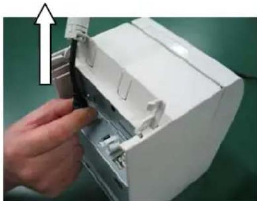
natural_image
Hand inserting a black cable into a white electronic device casing (no text or symbols visible)natural_image
Technical line drawing of two open battery compartments with internal mechanisms, one open and one closed, both showing a circular symbol (no text or labels)natural_image
Technical line drawing of a mechanical device with a lever and rotating arrow (no text or symbols)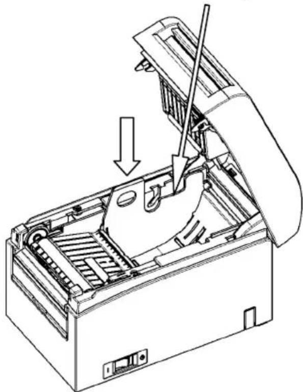
natural_image
Technical line drawing of a mechanical device with a tool inserted, showing internal components and a downward arrow indicating motion (no text or symbols present)natural_image
Technical line drawing of a mechanical device with an open lid and arrow indicating a component (no text or symbols present)natural_image
Line drawing of an open industrial machine with a cross symbol indicating cancellation (no text or labels present)natural_image
Line drawing of an open industrial machine with a paper roll and internal components (no text or symbols)natural_image
Two abstract circular patterns with a circle and an 'X' symbol, no text or labels present.natural_image
Hand inserting a printer into a paper airplane into a green background (no text or symbols visible)<< Verfahren>>
<< Verfahren>>
<< Verfahren>>
natural_image
Hand inserting a printer into a white paper airplane on a green background (no text or symbols visible)<< Verfahren>>
<< Verfahren>>
<< Verfahren>>
natural_image
Close-up of a white plastic panel or holder with black insulation, no visible text or symbols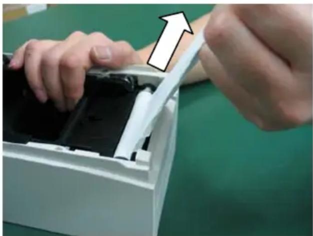
natural_image
Close-up of hands installing or adjusting a device into a white plastic container (no visible text or symbols)flowchart
graph TD
    A["Test Print"] --> B["End"]
    B --> C["Sample Print"]
    C --> D["Data Analysis"]
    D --> E["Cleaning"]
    E --> F["Sensor Adjustment"]
    F --> G["Setup"]
    G --> H["Test Print"]
    H --> I["Selection Item"]
    J["Special Mode"] --> K["Usage"]
    L["Item Selection"] --> M["Please push the feed switch short."]
    N["Item Decision"] --> O["Please push the feed switch long."]
    P["Paper feed direction"] --> Q
flowchart
graph TD
    A["Print Density ↑"] --> B["Print Color ↑"]
    B --> C["NV Graphics Memory ↑"]
    C --> D["User NV Memory"]
    D --> E["Return to Top Menu"]
    E --> F["Return to Up"]
    F --> G["Low Power"]
    G --> H["Max Speed"]
    H --> I["BK Density"]
    I --> J["Print Density"]
    J --> K["Print Color"]
    K --> L["NV Graphics Memory"]
    L --> M["User NV Memory"]
    M --> N["Selection Item"]
other
| Selection Item | Percentage (%) | |---|---| | 100% | ↑ | | 95% | ↑ | | 90% | ↑ | | 85% | ↑ | | 80% | ↑ | | 75% | ↑ | | 70% (Lightest) | ↑ | | 130% (Darkest) | 130% (Darkest) | | 125% | 125% | | 120% | 120% | | 115% | 115% | | 110% | 110% | | 105% | 105% | | 100% | 100% | | 95% | 95% | | 90% | 90% | | 85% | 85% | | 80% | 80% | | 75% | 75% | | 70% (Lightest) | 70% (Lightest) | Selection Item Paper feed directionflowchart
graph TD
    A["Test Print"] --> B["End"]
    B --> C["Sample Print"]
    C --> D["Data Analysis"]
    D --> E["Cleaning"]
    E --> F["Sensor Adjustment"]
    F --> G["Setup"]
    G --> H["Test Print"]
    H --> I["Selection Item"]
    J["Special Mode"] --> K["Usage"]
    K --> L["Item Selection"]
    L --> M["Please push the feed switch short."]
    L --> N["Item Decision"]
    N --> O["Please push the feed switch long."]
    P["Paper feed direction"] --> Q
flowchart
graph TD
    A["Return to Top Menu"] --> B["Sensor Auto Adjust"]
    B --> C["Mark Feed with Cut"]
    C --> D["Feed at Power On"]
    D --> E["Layout Er Recovery"]
    E --> F["Layout Er Process"]
    F --> G["TearOff Adjustment"]
    G --> H["Base Adjustment"]
    H --> I["Paper Width"]
    I --> J["Paper Detection"]
    J --> K["Selection Item"]
    K --> L["9th (High Speed)"]
    M["Paper feed direction"] --> N
Paper feed direction
flowchart
graph TD
    A["Return to Top Menu"] --> B["Return to Up"]
    B --> C["Sensor Auto Adjust"]
    C --> D["Mark Feed with Cut"]
    D --> E["Feed at Power On"]
    E --> F["Layout Er Recovery"]
    F --> G["Layout Er Process"]
    G --> H["TearOff Adjustment"]
    H --> I["Base Adjustment"]
    I --> J["Paper Width"]
    J --> K["Paper Detection"]
    K --> L["Selection Item"]
    L --> M["Paper Setting"]
    N["Paper feed direction"] --> O["-->"]
flowchart
graph TD
    A["Feed at Power On ↑"] --> B["Layout Er Recovery ↑"]
    B --> C["Layout Er Process ↑"]
    C --> D["TearOff Adjustment ↑"]
    D --> E["Base Adjustment ↑"]
    E --> F["Paper Width ↑"]
    F --> G["Paper Detection"]
    G --> H["Return to Top Menu Return to Up Sensor Auto Adjust Mark Feed with Cut Feed at Power On Layout Er Recovery Layout Er Process TearOff Adjustment Base Adjustment Paper Width Paper Detection Selection Item"]
    H --> I["Paper feed direction ↓"]
flowchart
graph TD
    A["Enable"] --> B["Disable"]
    B --> C["Enable"]
    C --> D["Selection Item"]
    D --> E["Feed at Power On"]
    F["Paper feed direction"] --> G["End"]
flowchart
graph TD
    A["Feed at Power On"] --> B["Selection Item"]
    C["Enable"] --> D["Disable"]
    E["Enable"] --> F["Disable"]
    G["Enable"] --> H["Disable"]
    I["Disable"] --> J["Paper feed direction"]
flowchart
graph TD
    A["Return to Up"] --> B["Return to Top Menu"]
    B --> C["Return to Up"]
    C --> D["Sensor Auto Adjust"]
    D --> E["Mark Feed with Cut"]
    E --> F["Feed at Power On"]
    F --> G["Layout Er Recovery"]
    G --> H["Layout Er Process"]
    H --> I["TearOff Adjustment"]
    I --> J["Base Adjustment"]
    J --> K["Paper Width"]
    K --> L["Paper Detection"]
    L --> M["Selection Item"]
    M --> N["Disable"]
flowchart
graph TD
    A["Test Print"] --> B["End"]
    B --> C["Sample Print"]
    C --> D["Data Analysis"]
    D --> E["Cleaning"]
    E --> F["Sensor Adjustment"]
    F --> G["Setup"]
    G --> H["Test Print"]
    H --> I["Selection Item"]
    J["Special Mode"] --> K["Usage"]
    L["Item Selection"] --> M["Please push the feed switch short."]
    N["Item Decision"] --> O["Please push the feed switch long."]
    P["Paper feed direction"] --> Q
flowchart
graph TD
    A["Setup ↑"] --> B["Test Print"]
    B --> C["End\nSample Print\nData Analysis\nCleaning\nSensor Adjustment\nSetup\nTest Print\nSelection Item"]
    C --> D["Paper feed direction ↓"]
flowchart
graph TD
    A["End"] --> B["Default Set"]
    B --> C["Setup Print"]
    C --> D["Setup"]
    D --> E["End"]
    style D fill:#f9f,stroke:#333
    note right of E "Selection Item"
    note right of F "Paper feed direction"
flowchart
graph TD
    A["Setup ↑"] --> B["Test Print"]
    B --> C["End\nSample Print\nData Analysis\nCleaning\nSensor Adjustment\nSetup\nTest Print\nSelection Item"]
    C --> D["Paper feed direction"]
flowchart
graph TD
    A["Paper Detection"] --> B["Return to Top Menu"]
    B --> C["Return to Up"]
    C --> D["Sensor Auto Adjust"]
    D --> E["Mark Feed with Cut"]
    E --> F["Feed at Power On"]
    F --> G["Layout Er Recovery"]
    G --> H["Layout Er Process"]
    H --> I["TearOff Adjustment"]
    I --> J["Base Adjustment"]
    J --> K["Paper Width"]
    K --> L["Paper Detection"]
    L --> M["Selection Item"]
    M --> N["Paper Setting"]
flowchart
graph TD
    A["Paper Width ↑"] --> B["Return to Top Menu"]
    B --> C["Return to Up"]
    C --> D["Sensor Auto Adjust"]
    D --> E["Mark Feed with Cut"]
    E --> F["Feed at Power On"]
    F --> G["Layout Er Recovery"]
    G --> H["Layout Er Process"]
    H --> I["TearOff Adjustment"]
    I --> J["Base Adjustment"]
    J --> K["Paper Width"]
    K --> L["Paper Detection"]
    L --> M["Selection Item"]
    M --> N["Paper feed direction ↓"]
flowchart
graph TD
    A["Return to Top Menu"] --> B["Return to Top Menu Others"]
    B --> C["Serial Condition"]
    C --> D["Customize Value"]
    D --> E["Memory Switch"]
    E --> F["Paper Setting"]
    F --> G["Selection Item"]
    G --> H["Return to Up"]
    I["Paper feed direction"] --> A
flowchart
graph TD
    A["Setup"] --> B["Return to Top Menu"]
    B --> C["Paper Setting"]
    C --> D["Selection Item"]
    D --> E["Paper Setting"]
    E --> F["Customize Value"]
    F --> G["Custom Condition"]
    G --> H["Others"]
    H --> I["Others"]
    I --> J["Customize Value"]
    J --> K["Custom Condition"]
    K --> L["Custom Condition"]
    L --> M["Custom Condition"]
    M --> N["Custom Condition"]
    N --> O["Custom Condition"]
    O --> P["Custom Condition"]
    P --> Q["Custom Condition"]
    Q --> R["Custom Condition"]
    R --> S["Custom Condition"]
    S --> T["Custom Condition"]
    T --> U["Custom Condition"]
    U --> V["Custom Condition"]
    V --> W["Custom Condition"]
    W --> X["Custom Condition"]
    X --> Y["Custom Condition"]
    Y --> Z["Custom Condition"]
    Z --> AA["Custom Condition"]
    AA --> AB["Custom Condition"]
    AB --> AC["Custom Condition"]
    AC --> AD["Custom Condition"]
    AD --> AE["Custom Condition"]
    AE --> AF["Custom Condition"]
    AF --> AG["Custom Condition"]
    AG --> AH["Custom Condition"]
    AH --> AI["Custom Condition"]
    AI --> AJ["Custom Condition"]
    AJ --> AK["Custom Condition"]
    AK --> AL["Custom Condition"]
    AL --> AM["Custom Condition"]
    AM --> AN["Custom Condition"]
    AN --> AO["Custom Condition"]
    AO --> AP["Custom Condition"]
    AP --> AQ["Custom Condition"]
    AQ --> AR["Custom Condition"]
    AR --> AS["Custom Condition"]
    AS --> AT["Custom Condition"]
    AT --> AU["Custom Condition"]
    AU --> AV["Custom Condition"]
    AV --> AW["Custom Condition"]
    AW --> AX["Custom Condition"]
    AX --> AY["Custom Condition"]
    AY --> AZ["Custom Condition"]
    AZ --> BA["Custom Condition"]
    BA --> BB["Custom Condition"]
    BB --> BC["Custom Condition"]
    BC --> BD["Custom Condition"]
    BD --> BE["Custom Condition"]
    BE --> BF["Custom Condition"]
    BF --> BG["Custom Condition"]
    BG --> BH["Custom Condition"]
    BH --> BI["Custom Condition"]
    BI --> BJ["Custom Condition"]
    BJ --> BK["Custom Condition"]
    BK --> BL["Custom Condition"]
    BL --> BM["Custom Condition"]
    BM --> BN["Custom Condition"]
    BN --> BO["Custom Condition"]
    BO --> BP["Custom Condition"]
    BP --> BQ["Custom Condition"]
    BQ --> BR["Custom Condition"]
    BR --> BS["Custom Condition"]
    BS --> BT["Custom Condition"]
    BT --> BU["Custom Condition"]
    BU --> BV["Custom Condition"]
    BV --> BW["Custom Condition"]
    BW --> BX["Custom Condition"]
    BX --> BY["Custom Condition"]
    BY --> BZ["Paper Feed Direction"]
Paper feed direction
flowchart
graph TD
    A["Disable"] --> B["Enable"]
    B --> C["Selection Item"]
    C --> D["Batch (OTHER IF)"]
    style A fill:#f9f,stroke:#333
    style D fill:#bbf,stroke:#333
    note right of D Paper feed direction
flowchart
graph TD
    A["Enable ↑"] --> B["Disable"]
    B --> C["Disable Enable Selection Item"]
    C --> D["Batch (OTHER IF)"]
    E["Paper feed direction"] --> F
flowchart
graph TD
    A["Return to Top Menu"] --> B["Return to Top Menu Others"]
    B --> C["Serial Condition"]
    C --> D["Customize Value"]
    D --> E["Memory Switch"]
    E --> F["Paper Setting"]
    F --> G["Selection Item"]
    G --> H["Return to Up"]
    I["Paper feed direction"] --> A
flowchart
graph TD
    A["Test Print"] --> B["End"]
    B --> C["Sample Print"]
    C --> D["Data Analysis"]
    D --> E["Cleaning"]
    E --> F["Sensor Adjustment"]
    F --> G["Setup"]
    G --> H["Test Print"]
    H --> I["Selection Item"]
    J["Special Mode"] --> K["Usage"]
    L["Item Selection"] --> M["Please push the feed switch short."]
    N["Item Decision"] --> O["Please push the feed switch long."]
    P["Paper feed direction"] --> Q
flowchart
graph TD
    A["Test Print"] --> B["Setup ↑"]
    B --> C["Sensor Adjustment ↑"]
    C --> D["Selection Item"]
    D --> E["End Adjustment Print"]
    E --> F["Adjustment"]
    F --> G["Adjustment Adjustment"]
    G --> H["Adjustment Adjustment"]
    H --> I["Adjustment Adjustment"]
    I --> J["Adjustment Adjustment"]
    J --> K["Adjustment Adjustment"]
    K --> L["Adjustment Adjustment"]
    L --> M["Adjustment Adjustment"]
    M --> N["Adjustment Adjustment"]
    N --> O["Adjustment Adjustment"]
    O --> P["Adjustment Adjustment"]
    P --> Q["Adjustment Adjustment"]
    Q --> R["Adjustment Adjustment"]
    R --> S["Adjustment Adjustment"]
    S --> T["Adjustment Adjustment"]
    T --> U["Adjustment Adjustment"]
    U --> V["Adjustment Adjustment"]
    V --> W["Adjustment Adjustment"]
    W --> X["Adjustment Adjustment"]
    X --> Y["Adjustment Adjustment"]
    Y --> Z["Adjustment Adjustment"]
    Z --> AA["Adjustment Adjustment"]
    AA --> AB["Adjustment Adjustment"]
    AB --> AC["Adjustment Adjustment"]
    AC --> AD["Adjustment Adjustment"]
    AD --> AE["Adjustment Adjustment"]
    AE --> AF["Adjustment Adjustment"]
    AF --> AG["Adjustment Adjustment"]
    AG --> AH["Adjustment Adjustment"]
    AH --> AI["Adjustment Adjustment"]
    AI --> AJ["Adjustment Adjustment"]
    AJ --> AK["Adjustment Adjustment"]
    AK --> AL["Adjustment Adjustment"]
    AL --> AM["Adjustment Adjustment"]
    AM --> AN["Adjustment Adjustment"]
    AN --> AO["Adjustment Adjustment"]
    AO --> AP["Adjustment Adjustment"]
    AP --> AQ["Adjustment Adjustment"]
    AQ --> AR["Adjustment Adjustment"]
    AR --> AS["Adjustment Adjustment"]
    AS --> AT["Adjustment Adjustment"]
    AT --> AU["Adjustment Adjustment"]
    AU --> AV["Adjustment Adjustment"]
    AV --> AW["Adjustment Adjustment"]
    AW --> AX["Adjustment Adjustment"]
    AX --> AY["Adjustment Adjustment"]
flowchart
graph TD
    A["Adjustment Print"] --> B["Adjustment"]
    B --> C["End Adjustment Print Adjustment Selection Item"]
    D["Pacer feed direction"] --> E
flowchart
graph TD
    A["Test Print"] --> B["End"]
    B --> C["Sample Print"]
    C --> D["Data Analysis"]
    D --> E["Cleaning"]
    E --> F["Sensor Adjustment"]
    F --> G["Setup"]
    G --> H["Test Print"]
    H --> I["Selection Item"]
    I --> J["Special Mode"]
    J --> K["Usage"]
    K --> L(Item Selection]
    L --> M["Please push the feed switch short."]
    L --> N(Item Decision]
    N --> O["Please push the feed switch long."]

flowchart
graph TD
    A["Data Analysis ↑"] --> B["Cleaning ↑"]
    B --> C["Sensor Adjustment ↑"]
    C --> D["Setup ↑"]
    D --> E["Test Print"]
    E --> F["End Sample Print Data Analysis Cleaning Sensor Adjustment Setup Test Print Selection Item"]
    style E fill:#f9f,stroke:#333
flowchart
graph TD
    A["Test Print"] --> B["End"]
    B --> C["Sample Print"]
    C --> D["Data Analysis"]
    D --> E["Cleaning"]
    E --> F["Sensor Adjustment"]
    F --> G["Setup"]
    G --> H["Test Print"]
    H --> I["Selection Item"]
    I --> J["Special Mode"]
    J --> K["Usage"]
    K --> L["Item Selection"]
    L --> M["Please push the feed switch short."]
    L --> N["Item Decision"]
    N --> O["Please push the feed switch long."]
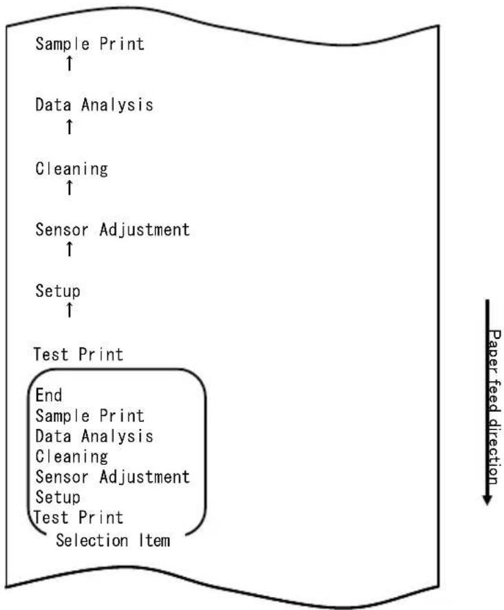
flowchart
graph TD
    A["Sample Print ↑"] --> B["Data Analysis ↑"]
    B --> C["Cleaning ↑"]
    C --> D["Sensor Adjustment ↑"]
    D --> E["Setup ↑"]
    E --> F["Test Print"]
    F --> G["End Sample Print Data Analysis Cleaning Sensor Adjustment Setup Test Print Selection Item"]
    style F fill:#f9f,stroke:#333
    note right of F Paper feed direction
| name | Pizza |
| Ingredient | Wheat, Yeast, Olives, Olive oil, Tomato, Mozzarella cheese, Basil Oregano, Onions, Capers, Sausage, Chile Peppers, Mushrooms Anchovies |
| Expiration | XX-XX-20xx |
| Manufacturer | OK! Food Ltd. |
„LABEL3“-Muster
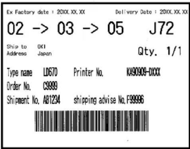
„LABEL4“-Muster

„LABEL5“-Muster
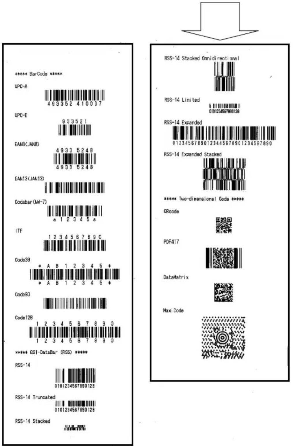
natural_image
Simple downward-pointing arrow shape with no text or symbolsnatural_image
Hand placing a black plastic component into a white plastic housing (no text or symbols visible)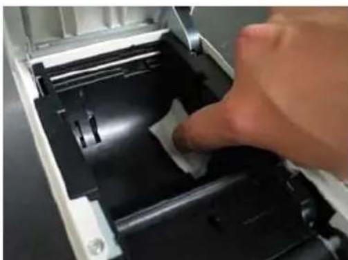
natural_image
Close-up of a hand pressing down on a mechanical component with a white paper clip (no visible text or symbols)Paper feed direction
flowchart
graph TD
    A["Cleaning ↑"] --> B["Sensor Adjustment ↑"]
    B --> C["Setup ↑"]
    C --> D["Test Print"]
    D --> E["End Sample Print Data Analysis Cleaning Sensor Adjustment Setup Test Print Selection Item"]
    E --> F["Special Mode"]
    F --> G["Usage"]
    G --> H["Item Selection Please push the feed switch short. Item Decision Please push the feed switch long."]
natural_image
Two screwdriver tools on a dark surface, one with a metallic tip and the other with a black handle (no text or symbols visible)
Paper feed direction
flowchart
graph TD
    A["Cleaning ↑"] --> B["Sensor Adjustment ↑"]
    B --> C["Setup ↑"]
    C --> D["Test Print"]
    D --> E["End Sample Print Data Analysis Cleaning Sensor Adjustment Setup Test Print Selection Item"]
    E --> F["Special Mode"]
    F --> G["Usage"]
    G --> H["Item Selection Please push the feed switch short. Item Decision Please push the feed switch long."]
natural_image
Pure electrical circuit lines without any symbolsBuchsenansicht
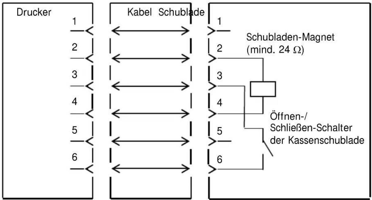
natural_image
Line drawing of a rectangular electronic device with lid and ventilation slots (no text or symbols)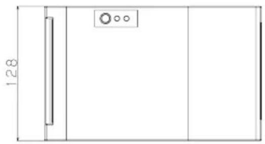
natural_image
Pure technical line drawing of a door or cabinet with no text, numbers, or symbols
natural_image
Line drawing of a portable electronic device with ventilation slots and control buttons (no text or symbols)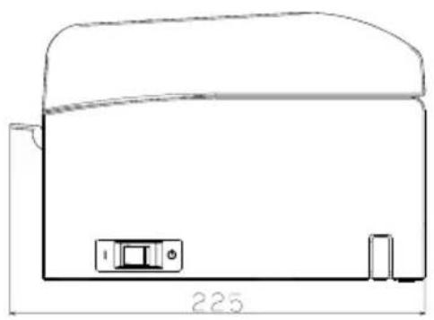
natural_image
Technical line drawing of a mechanical component with dimension标注 (no text or symbols)Papierführung
natural_image
Line drawing of a device with a handle and internal components (no text or symbols)natural_image
Technical line drawing of a cylindrical mechanical component with mounting holes and internal brackets (no text or symbols)natural_image
Technical line drawing of a mechanical component with multiple slots and a central hub (no text or symbols)natural_image
Line drawing of a portable electronic device with a lid and base mount (no text or symbols)natural_image
Technical line drawing of a mechanical device with internal components and a zoomed-in view (no text or symbols)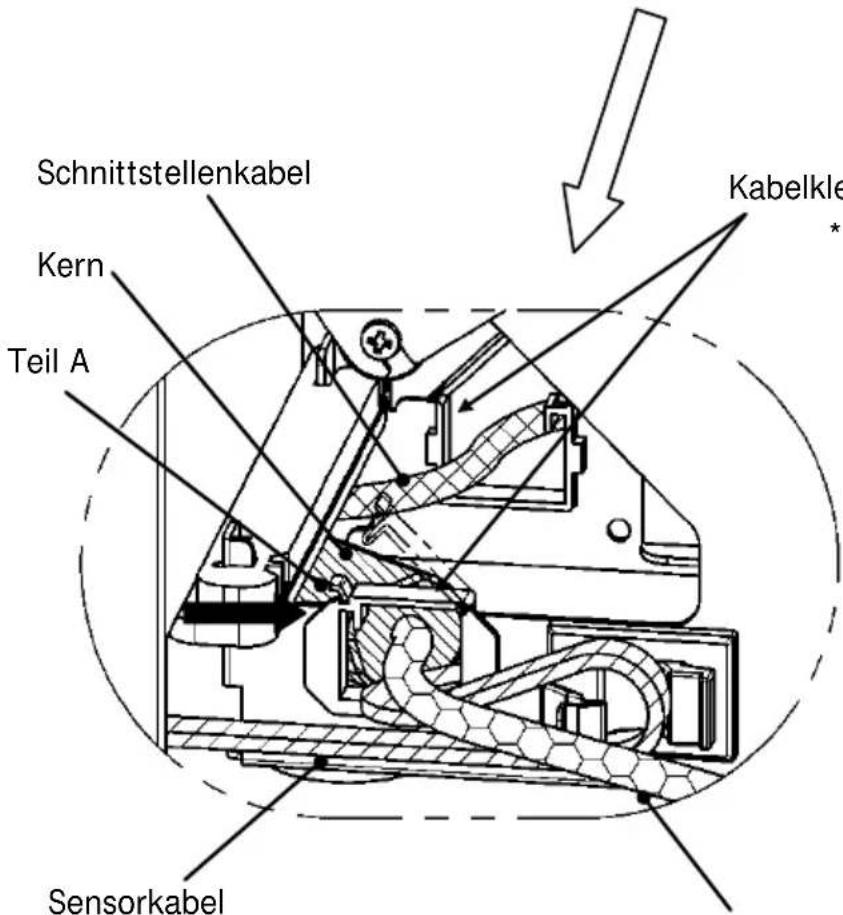
natural_image
Technical line drawing of a mechanical device with internal components and a base panel (no text or symbols)
natural_image
Technical diagram showing internal mechanical assembly before and after division (no text or labels)natural_image
Technical line drawing of a mechanical device with internal components and an upward arrow indicating motion (no text or symbols)natural_image
Technical line drawing of a mechanical device with internal components and an arrow indicating motion (no text or symbols)natural_image
Technical line drawing of a mechanical device with no visible text or symbolsnatural_image
Technical line drawing of a mechanical assembly with no visible text or symbols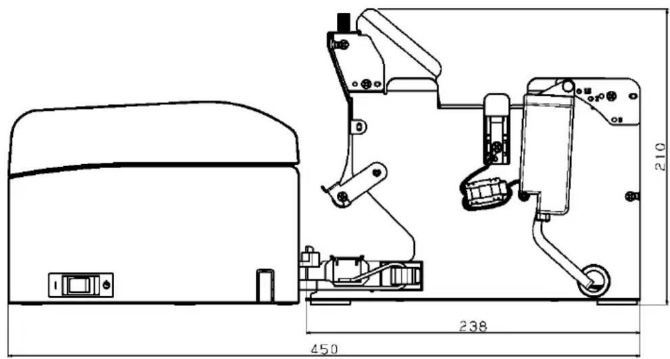
Oki Systems (UK) Ltd
Blays House
Wick Road
Egham
Surrey
TW20 0HJ
Tel: +44 (0) 1784 274300
Fax: +44 (0) 1784 274301
http://www.oki.co.uk
Oki Systems Ireland Limited
The Square Industrial Complex Tallaght
Dublin 24
Tel: +353 (0) 1 4049590
Fax: +353 (0)1 4049591
http://www.oki.ie
Oki Systems Ireland Limited - Northern Ireland
19 Ferndale Avenue
Glengormley
BT36 5AL
Northern Ireland
Tel: +44 (0) 7767 271447
Fax: +44 (0) 1 404 9520
http://www.oki.ie
Technical Support for all Ireland:
Tel: +353 1 4049570
Fax: +353 1 4049555
E-mail: tech.support@oki.ie
OKI Systems (Czech and Slovak), s.r.o.
Futurama Business Park -
Sokolovská 651/136A
186 00 Praha 8
Czech Republic
Tel: +420 224 890158
Fax:+420 22 232 6621
Website: www.oki.cz, www.oki.sk
Albania, Bosnia, Bulgaria, Croatia,
Cyprus, Estonia, Greece, Israel,
Latvia, Lithuania, Macedonia,
Romania, Serbia, Slovenia
CEE Export Group: OKI Systems (Poland) Ltd
ul. Domaniewska 42
02-672 Warsaw
Poland
Tel: +48 (0) 22 448 65 00
Fax: +48 (0) 22 448 65 0
E-mail: tech@oki.com.pl
Platinum Business Park II, 3rd Floor
ul. Domaniewska 42
02-672 Warsaw
Poland
Tel: +48 22 448 65 00
Fax: +48 22 448 65 01
Website: www.oki.com.pl
E-mail: oki@oki.com.pl
Hotline: 0800 120066
E-mail: tech@oki.com.pl
OKI Systems Rus, LLC (Russia)
Sector B, 3rd Floor, Svyatogor-4
Business Center10/4, Letnikovskaya
str.115114, Moscow
Tel: +7 495 276 5060
Fax: +7 495 258 6070
e-mail: info@oki.ru
Website: www.oki.ru
Technical support:
Tel: +7 495 564 8421
e-mail: tech@oki.ru
Raisy Opkinoy Street,8
Building B, 2 ^nd Floor,
Kiev 02002
Ukraine
Tel: +380 44 537 5288
e-mail: event@oki.ua
Website: www.oki.ua
Oki Systems (Belgium)
Medialaan 24
1800 Vilvoorde
Helpdesk: 02-2574620
Fax: 02 2531848
Website: www.oki.be
OKI Systems (Danmark) a·s
Herstedøstervej 27
2620 Albertslund
Danmark
Oki Systems (Norway) AS
Tevlingveien 23
N-1081 Oslo
Tel: +47 (0) 63 89 36 00
Telefax: +47 (0) 63 89 36 01
Website: www.oki.no
Var vänlig kontakta din
Oki Systems (Sweden) AB
Borgafjordsgatan 7
Box 1193
164 26 Kista
Tel. +46 (0) 8 634 37 00
e-mail: info@oki.se
Website: www.oki.se
2000 Bishops Gate Blvd.
http://WWW.OKIPRINTINGSOLUTIONS.COM
http://my.okidata.com
Oki Data Americas Inc.(Canada • Canadá)
4140B Sladeview Crescent Unit 7 & 8
Mississauga, Ontario
Canada L5L 6A1
Tél: 1-905-608-5000
Téléc: 1-905-608-5040
http://WWW.OKIPRINTINGSOLUTIONS.COM
Oki Data Americas Inc.(América Latina (OTRO))
2000 Bishops Gate Blvd.
HTTP://www.okiprintingsolutions.com
Argentina/ Chile/ Paraguay/ Perú/ Uruguay
Oki Data Americas, Inc.
Sucursal Argentina
Ugarte 3610 Piso 4°(1605) Olivos
Buenos Aires, Argentina
TEL: +54 11 5288 7500
Fax: +54 11 5288 7599
Colombia/ Ecuador/ Venezuela/ Centroamérica y Caribe Oki Data Americas, Inc.
Sucursal Colombia
1168/81-82 Lumpini Tower, 27th Floor Rama IV Road
Tungmahamek, Sathorn
Bangkok 10120
Tel: (662) 679 9235
Fax: (662) 679 9243/245
http://www.okisysthai.com
Oki Data(Australia) Pty Ltd.
Level1 67 Epping Road, Macquare Park
NSW 2113, Australia
Tel: +61 2 8071 0000
(Support Tel: 1800 807 472)
Fax: +61 2 8071 0010
http://www.oki.com.au
OKI Data New Zealand
8 Antares Place Rosedale,
Auckland, 0632 New Zealand
Tel: (64) 9 477 0500
Fax: (64) 9 477 0549
http://www.oki.co.nz/
Oki Data(S) P Ltd. Malaysia Rep Office
Suite 21.03, 21st Floor Menara IGB, Mid Valley City,
Lingkaran Syed Pura 59200,
Kuala Lumpur, Malaysia
Tel: (60) 3 2287 1177
Fax: (60) 3 2287 1166
Guía del usuario
PREFACIO
© 2011 Oki Data Corporation
Oki Data Corporation,
4-11-22 Shibaura, Minato-ku,
Tokio 108-8551,
Japón
Following information is only for the province of Buenos Aires in Argentine:
natural_image
Simple geometric diagram with concentric circles and a diagonal line, no text or symbols presentMANUAL
DRIVER DE LA IMPRESORA
PROGRAMA DE UTILIDAD
natural_image
Simple geometric diamond shape with no text or symbolsnatural_image
Simple geometric diamond shape with no text or symbols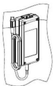
natural_image
Technical line drawing of a mechanical device with a coiled spring and housing (no text or symbols)natural_image
Abstract line drawing with concentric curved lines and a central loop, no text or symbols present2. Adaptador de CA
natural_image
Diagram of a mechanical device with an upward arrow and internal components (no text or symbols)natural_image
Technical line drawing of two open industrial enclosures with a circular inset showing a circle (no text or symbols)natural_image
Technical line drawing of a mechanical device with an open lid and arrow indicating direction (no text or symbols)natural_image
Line drawing of an open industrial machine with a cross symbol indicating cancellation (no text or labels present)natural_image
Technical line drawing of a mechanical device with open lid and paper sheet (no text or symbols)natural_image
Pure geometric shapes including circles, rectangles, and crosses without any text or symbolsnatural_image
Simple line drawings of two circular shapes and a cross, no text or symbols presentnatural_image
Hand inserting a printer into a white paper airplane into a green background (no text or symbols visible)<
<< Procedimiento>>
<< Procedimiento>>
natural_image
Hand inserting a printer into a green background (no text or symbols visible)<
<
<
natural_image
Close-up of a white plastic panel with black insulation and black plastic cladding, no visible text or symbols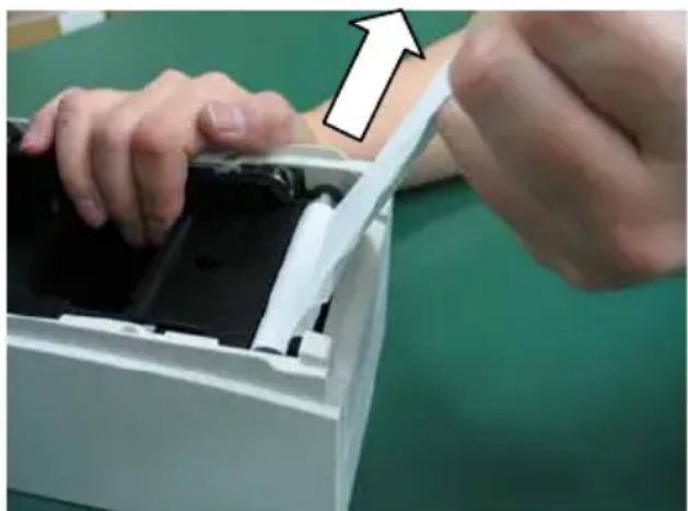
natural_image
Close-up of hands installing or adjusting a device into a white plastic container (no visible text or symbols)flowchart
graph TD
    A["Test Print"] --> B["End"]
    B --> C["Sample Print"]
    C --> D["Data Analysis"]
    D --> E["Cleaning"]
    E --> F["Sensor Adjustment"]
    F --> G["Setup"]
    G --> H["Test Print"]
    H --> I["Selection Item"]
    J["Special Mode"] --> K["Usage"]
    L["Item Selection"] --> M["Please push the feed switch short."]
    N["Item Decision"] --> O["Please push the feed switch long."]
    P["Paper feed direction"] --> Q
flowchart
graph TD
    A["Test Print"] --> B["End"]
    B --> C["Sample Print"]
    C --> D["Data Analysis"]
    D --> E["Cleaning"]
    E --> F["Sensor Adjustment"]
    F --> G["Setup"]
    G --> H["Test Print"]
    H --> I["Selection Item"]
    J["Special Mode"] --> K["Usage"]
    L["Item Selection"] --> M["Please push the feed switch short."]
    N["Item Decision"] --> O["Please push the feed switch long."]
    P["Paper feed direction"] --> Q
other
| Percentage (%) | Paper feed direction | | :--- | :--- | | 100 | ↑ | | 95 | ↑ | | 90 | ↑ | | 85 | ↑ | | 80 | ↑ | | 75 | ↑ | | 70 (Lightest) | ↑ | | 130 (Darkest) | — | | 130 (Darkest) | — | | 125 | — | | 120 | — | | 115 | — | | 110 | — | | 105 | — | | 100 | — | | 95 | — | | 90 | — | | 85 | — | | 80 | — | | 75 | — | | 70 (Lightest) | — | Selection Item Paper feed directionflowchart
graph TD
    A["Return to Top Menu"] --> B["Return to Top Menu Others"]
    B --> C["Serial Condition"]
    C --> D["Customize Value"]
    D --> E["Memory Switch"]
    E --> F["Paper Setting"]
    F --> G["Selection Item"]
    G --> H["Return to Up"]
    I["Paper feed direction"] --> A
flowchart
graph TD
    A["Test Print"] --> B["End"]
    B --> C["Sample Print"]
    C --> D["Data Analysis"]
    D --> E["Cleaning"]
    E --> F["Sensor Adjustment"]
    F --> G["Setup"]
    G --> H["Test Print"]
    H --> I["Selection Item"]
    J["Special Mode"] --> K["Usage"]
    K --> L(Item Selection]
    L --> M["Please push the feed switch short."]
    L --> N(Item Decision]
    N --> O["Please push the feed switch long."]
    P["Paper feed direction"] --> Q
flowchart
graph TD
    A["Return to Top Menu"] --> B["Sensor Auto Adjust"]
    B --> C["Mark Feed with Cut"]
    C --> D["Feed at Power On"]
    D --> E["Layout Er Recovery"]
    E --> F["Layout Er Process"]
    F --> G["TearOff Adjustment"]
    G --> H["Base Adjustment"]
    H --> I["Paper Width"]
    I --> J["Paper Detection"]
    J --> K["Selection Item"]
    K --> L["9th (High Speed)"]
    M["Paper feed direction"] --> N
flowchart
graph TD
    A["Test Print"] --> B["End"]
    B --> C["Sample Print"]
    C --> D["Data Analysis"]
    D --> E["Cleaning"]
    E --> F["Sensor Adjustment"]
    F --> G["Setup"]
    G --> H["Test Print"]
    H --> I["Selection Item"]
    J["Special Mode"] --> K["Usage"]
    L["Item Selection"] --> M["Please push the feed switch short."]
    N["Item Decision"] --> O["Please push the feed switch long."]
    P["Paper feed direction"] --> Q
flowchart
graph TD
    A["Setup ↑"] --> B["Test Print"]
    B --> C["End Sample Print\nData Analysis\nCleaning\nSensor Adjustment\nSetup\nTest Print\nSelection Item"]
    C --> D["Paper feed direction ↓"]
- MANUFACTURER
- IMPORTER TO THE EU/AUTHORISED REPRESENTATIVE
- ENVIRONMENTAL INFORMATION
- Description of Safety symbols displayed on the equipment
- Notes on Use
- Notes on printing and the paper used
- Notes on using the cutter
- Notes on printing of barcodes and two-dimensional codes
- Notes on using the printer through the USB interface
- Note on installation
- Note on the modular connector
- Note on using the printer in special mode
- TABLE OF CONTENTS
- Regular Cleaning 174
- Interface 188
- Specifications 195
- Roll Paper Unit 204
- Appearance and Names of Components
- Appended goods
- AC Adapter
- 2-1. AC adapter
- Paper Specifications
- 3-1. Paper Width
- 3-2. Paper Thickness
- 3-3. Forms of Paper
- 3-4. Paper Types
- 3-4-1. Requirements for full-sheet label paper
- 3-4-2. Conditions for using black mark paper
- 3-4-3. Conditions for using die-cut label paper
- 3-5. Recommended Thermal Paper
- Preparations
- 4-1. Connecting Interface Cable
- LAN interface model
- For a unit with Dual interface
- 4-2. Connecting the drawer kick cable
- 4-3. Connecting the AC Adapter
- 4-4. Disconnecting the AC Adapter
- 4-5. Turning on the Power
- Inserting Paper for Printing
- 5-1. Opening the Top Cover
- 5-2. Setting the Paper Width
- 5-2-1. Mounting separator A
- 5-2-2. Removing separators A and B
- Removing separator A
- 5-2-3. Attaching separators A and B
- Attaching separator A
- 5-3. Loading Paper
- 5-3-1. Loading roll paper
- 5-3-2. Loading fanfold paper
- 5-4. Setting the Paper Guide
- 5-5. Closing the Top Cover
- Setting Up the Printer
- Introduction to printer setup procedures
- Detection of paper layout information
- 6-1. Paper Information Setting Using the Driver
- Printer setup flow
- Installing the driver
- Paper layout detection
- Custom paper creation
- Printing from an application
- 6-1-1. Paper layout
- 6-1-2. Custom paper
- 6-1-3. Printing from an application
- 6-2. Paper information setting using the utility
- 6-2-1. Paper layout
- 6-2-2. Setting detailed paper layout information
- <>
- 6-3. Setting Paper Information Using the Printer
- 6-3-1. Automatic layout detection
- 6-3-2. Setting the Paper Width
- 6-3-3. Automatic layout detection
- Black mark paper
- Die-cut label paper
- Plain paper (including full-sheet label paper)
- 6-4. Replacing paper
- Automatic layout detection
- Updating the layout information
- 6-5. Paper Layout Errors
- 6-6. Adjusting Sensors
- ■ Automatic sensor adjustment
- ■ Manual sensor adjustment
- 6-7. Print Density Setting
- 6-8. Print Speed Setting
- 6-9. Cutting Position Correction
- 6-10. Other Settings
- 6-11. Initializing the Printer Setup Information
- Control Panel
- 7-1. Control Panel
- FEED switch
- 7-2. Error Indications
- Unrecoverable errors
- Preventing and Clearing Paper Jams
- 8-1. Preventing Paper Jams
- 8-2. Clearing a Paper Jam
- Troubleshooting
- 9-1. Power-on Problems and Errors
- 9-2. Cutter-related Problems
- Special Modes
- 10-1. Test Printing
- Sample test printout
- 10-2. Setting Up the Printer
- Example (1): Changing the Print Density
- The procedure for this setting is as follows.
- Example (2): Changing the Max Speed
- Select "9th" as your option.
- Example (3): Changing the Print Color
- Example (4) Changing the Feed at Power On
- The procedure for this setting is as follows:
- Example (5) Initializing the printer settings
- Note on initialization
- The initialization procedure is as follows:
- The procedure for this setting change is as follows:
- Example (7) Changing the Paper Width
- Example (8) Changing the Batch(OTHER IF)
- Select "ENABLE" as your option.
- 10-3. Setup Items
- Setup group items
- 10-4. Sensor Adjustment
- 10-4-1. Sensor adjustment mode
- ■ How to select an item
- ADJUSTMENT
- 10-4-2. Black mark (BM) sensor adjustment
- 10-4-3. Adjusting the label sensor
- 10-4-4. Paper-near-end (PNE) sensor adjustment
- 10-4-5. Paper end (PE) sensor adjustment
- 10-5. Data Analysis
- HEX DUMP mode
- Command trace mode
- 10-6. Sample Print
- Regular Cleaning
- 11-1. Cleaning the Paper Holder and Paper Transport
- 11-2. Cleaning the Platen Roller
- 11-3. Cleaning the Thermal Head
- 11-4. Cleaning the Cutter Blade and Frame
- Interface
- 12-1. LAN Interface
- 12-2. Dual Interface
- 12-3. Drawer Kick Connector
- 12-4. Specifications of Power Supply
- Specifications
- 13-1. General Specifications
- 13-2. Cutter Specifications
- 13-3. Paper Supply Specifications
- 13-4. Interface Specifications
- 13-5. Environment Specifications
- 13-6. Specifications of Reliability
- Printer life
- Head
- Cutter
- - Label cutting
- Roll Paper Unit
- 14-1. Outline
- 14-2. Nomenclature
- 14-3. Paper Specifications
- 14-4. Roll Paper Feed Specifications
- 14-5. Roll Paper Unit Installation Procedure
- 14-6. Method of setting PNE sensor
- 14-7. Method of setting guide plate
- 14-8. Setting the Roll Paper
- 14-9. Roll Paper Unit Appearance
- Oki Systems (UK) Ltd
- Oki Systems Ireland Limited
- Oki Systems Ireland Limited - Northern Ireland
- OKI Systems (Czech and Slovak), s.r.o.
- CEE Export Group: OKI Systems (Poland) Ltd
- OKI Systems Rus, LLC (Russia)
- Oki Systems (Belgium)
- OKI Systems (Danmark) a·s
- Oki Systems (Norway) AS
- Oki Systems (Sweden) AB
- Oki Data Americas Inc.(Canada • Canadá)
- Oki Data Americas Inc.(América Latina (OTRO))
- Argentina/ Chile/ Paraguay/ Perú/ Uruguay
- Oki Data Americas, Inc.
- Colombia/ Ecuador/ Venezuela/ Centroamérica y Caribe Oki Data Americas, Inc.
- Oki Data(Australia) Pty Ltd.
- OKI Data New Zealand
- Oki Data(S) P Ltd. Malaysia Rep Office
- Mode HEX DUMP (vidage hexadécimal)
- Manuale d'uso
- PREFAZIONE
- Modo HEX DUMP
- Benutzerhandbuch
- VORWORT
- Netzteil
- 2-1. Netzteil
- Guía del usuario
- PREFACIO
- Adaptador de CA
Brand : OKI
Model : LD670
Category : Label printer