
HIHM934M - Cooker ASKO - Free user manual and instructions
Find the device manual for free HIHM934M ASKO in PDF.
| Product type | Induction cooktop with integrated extractor |
| Brand | ASKO |
| Model | HIHM934M |
| Dimensions (HxWxD) | 150 x 870 x 522 mm |
| Supply voltage | 220-240 V / 380-415 V, 50/60 Hz |
| Total power | 7400 W (cooktop) + 168 W (extractor motor) |
| Number of cooking zones | 4 (induction) |
| Dimensions of cooking zones | 19 x 22 cm (non-circular) |
| Control type | Touch Control (sensitive keys) |
| Power function | Yes (maximum power for 10 min) |
| Pause function | Yes (temporary interruption) |
| Keep warm function | Yes (3 levels: 42°C, 70°C, 94°C) |
| Timer | Automatic shutoff and hourglass (0-99 min) |
| Child safety | Yes (lock) |
| Pan detection | Yes (induction) |
| Integrated extractor system | Yes (4 levels + intensive) |
| Grease filter | Dishwasher-safe |
| Activated carbon filter | Replacement after 150 hours of service |
| Cleaning the hob | Special products for ceramic glass |
| Installation type | Built-in (flush or on countertop) |
| Residual heat indicator | Yes (H display) |
| Key lock | Yes |
| Power cord length | 1.85 m |
Frequently Asked Questions - HIHM934M ASKO
User questions about HIHM934M ASKO
0 question about this device. Answer the ones you know or ask your own.
Ask a new question about this device
Download the instructions for your Cooker in PDF format for free! Find your manual HIHM934M - ASKO and take your electronic device back in hand. On this page are published all the documents necessary for the use of your device. HIHM934M by ASKO.
USER MANUAL HIHM934M ASKO
Instructions for usage and installation
Induction hob with integrated extractor
1.1 For your information.. 2
1.2 Intended use 2
2 Safety Instructions andWarnings 3
2.1 For connection and operation 3
2.2 General information about the hob 3
2.3 For persons 4
2.4 Explanation for symbols and indications 5
3.1 Operating the hob with the sensor keys 7
3.2 Worth knowing about the slider (sensorf eld) .... 7
3 Appliance description 6
4 Operation 8
4.1 The induction hob 8
4.2 Pan recognition 8
4.3 Operation time limit 8
4.4 Other functions 8
4.5 Protection against overheating (induction) 8
4.6 Cookware for induction hobs 9
4.7 How to cut power consumption 9
4.8 Power levels 9
4.9 Residual heat display 9
4.10 Operating the keys 10
4.11 Switching on the induction hob and cooking zone 10
4.12 Switching off a cooking zone 10
4.13 Switching off the induction hob 10
4.14 PAUSE function 11
4.15 Recall function 11
4.16 Childproof lock 12
4.17 Bridging function 12
4.18 Automatic switch-off (timer) 13
4.19 Minute minder (egg timer) 13
4.20 Automatic boost function 14
4.21 Keep-warm function 14
4.22 Locking 15
4.23 Power boost 15
4.24 Power management 15
4.25 Use extraction system 16
4.25.1 Switching the fan on and off 16
4.25.2 Adjustable after-run of the extraction system 16
4.25.3 Notes on runtime 17
4.25.4 Indication: Clean the grease fi Iters.. 17
4.25.5 Indication: Replace the charcoal fiiter 17
4.25.6 Turn off the carbon filter operating hours counter during the operation of the air exhaust .. 17
5 Cleaning and care 18
5.1 Glass ceramic plate 18
5.2 Extraction 19
6 What to do if trouble occurs? 20
7 Instructions for assembly 21
7.1 Safety instructions for kitchen unit fitters 21
7.2 Ventilation 21
7.3 Installation 21
7.4 Variable installation possibilities: Overlying installation 22
7.5 External dimensions 22
7.6 Installation of the extraction system 26
7.7 Electrical connection 27
7.8 Putting the appliance into operation 27
8 Technical Data 27
9 Effi cient Measurement Data Sheet 28
10 ECO data information 28
11 Decommissioning and disposal of the appliance 29
11.1 Switching the appliance off completely 29
11.2 Disposing of the packaging 29
11.3 Disposing of old appliances 29
1 General
1.1 For your information...
Please read this manual carefully before using your appliance. It contains important safety advice; it explains how to use and look after your appliance so that it will provide you with many years of reliable service.
Should a fault arise, please first consult the section on "What to do if trouble occurs?".
You can often rectify minor problems yourself, thus saving unnecessary service costs.
Please keep this manual in a safe place and pass it on to new owners for their information and safety.
1.2 Intended use
The hob is to be used solely for preparing food in the home or in other environments. Similar environments:
- Use in shops, offices and other similar working environments
- Use in agricultural enterprises
- Use by customers in hotels, motels and other typical living environments
- Use in breakfast buffets
- It may not be used for any other purpose and may only be used under supervision.
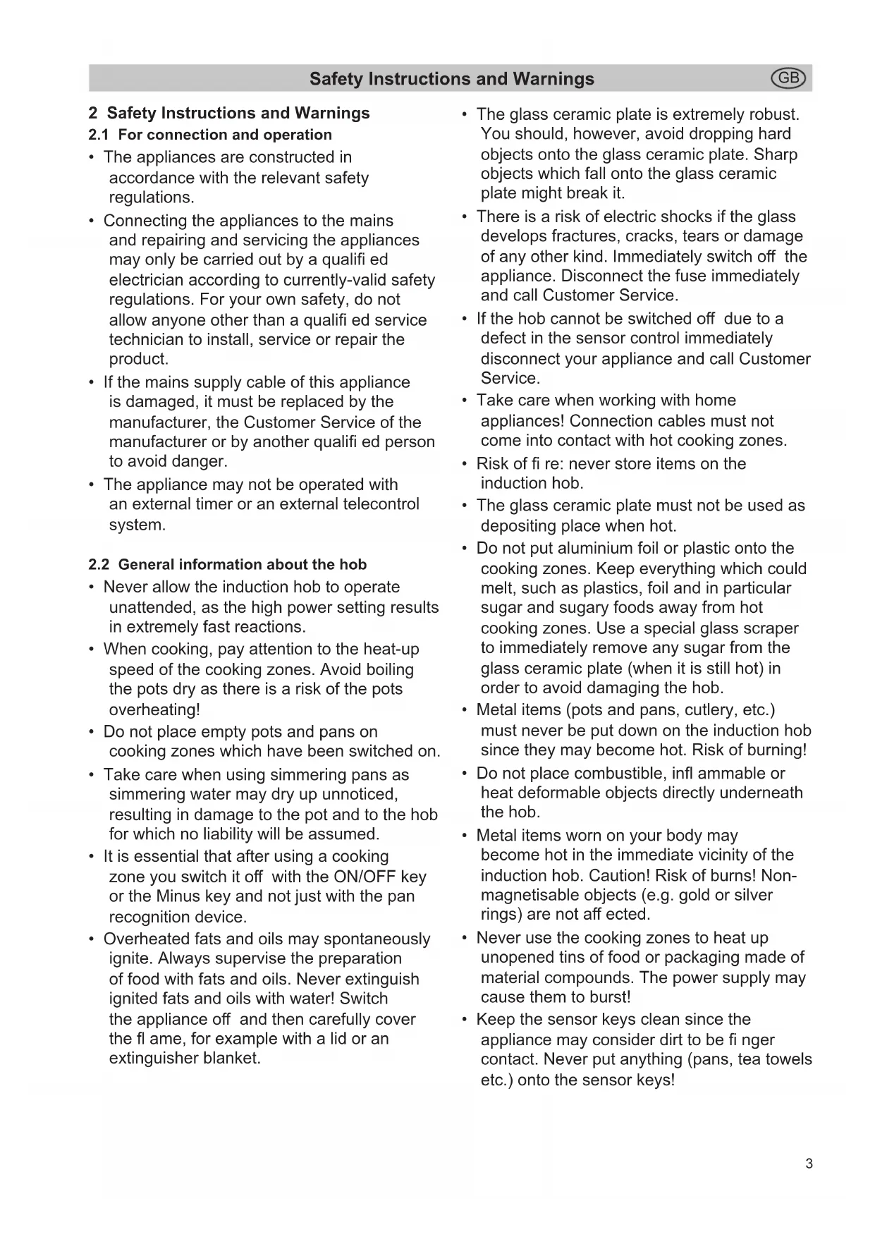
2 Safety Instructions andWarnings
2.1 For connection and operation
The appliances are constructed in accordance with the relevant safety regulations.
- Connecting the appliances to the mains and repairing and servicing the appliances may only be carried out by a qualified electrician according to currently-valid safety regulations. For your own safety, do not allow anyone other than a qualified service technician to install, service or repair the product.
- If the mains supply cable of this appliance is damaged, it must be replaced by the manufacturer, the Customer Service of the manufacturer or by another qualified person to avoid danger.
- The appliance may not be operated with an external timer or an external telecontrol system.
2.2 General information about the hob
- Never allow the induction hob to operate unattended, as the high power setting results in extremely fast reactions.
- When cooking, pay attention to the heat-up speed of the cooking zones. Avoid boiling the pots dry as there is a risk of the pots overheating!
- Do not place empty pots and pans on cooking zones which have been switched on.
Take care when using simmering pans as simmering water may dry up unnoticed, resulting in damage to the pot and to the hob for which no liability will be assumed. -
It is essential that after using a cooking zone you switch it off with the ON/OFF key or the Minus key and not just with the pan recognition device.
Overheated fats and oils may spontaneously ignite. Always supervise the preparation of food with fats and oils. Never extinguish ignited fats and oils with water! Switch the appliance off and then carefully cover the flame, for example with a lid or an extinguisher blanket. -
The glass ceramic plate is extremely robust. You should, however, avoid dropping hard objects onto the glass ceramic plate. Sharp objects which fall onto the glass ceramic plate might break it.
- There is a risk of electric shocks if the glass develops fractures, cracks, tears or damage of any other kind. Immediately switch off the appliance. Disconnect the fuse immediately and call Customer Service.
- If the hob cannot be switched off due to a defect in the sensor control immediately disconnect your appliance and call Customer Service.
Take care when working with home appliances! Connection cables must not come into contact with hot cooking zones. - Risk of fire: never store items on the induction hob.
- The glass ceramic plate must not be used as depositing place when hot.
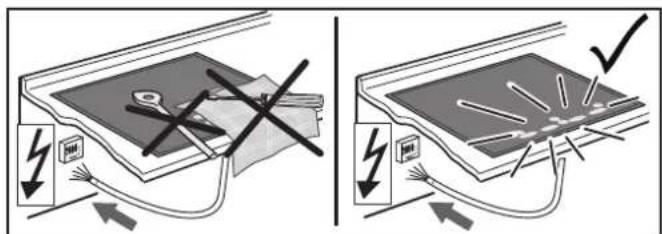
- Do not put aluminium foil or plastic onto the cooking zones. Keep everything which could melt, such as plastics, foil and in particular sugar and sugary foods away from hot cooking zones. Use a special glass scraper to immediately remove any sugar from the glass ceramic plate (when it is still hot) in order to avoid damaging the hob.
- Metal items (pots and pans, cutlery, etc.) must never be put down on the induction hob since they may become hot. Risk of burning!
- Do not place combustible, infl ammable or heat deformable objects directly underneath the hob.
- Metal items worn on your body may become hot in the immediate vicinity of the induction hob. Caution! Risk of burns! Non-magnetisable objects (e.g. gold or silver rings) are not affected.
- Never use the cooking zones to heat up unopened tins of food or packaging made of material compounds. The power supply may cause them to burst!
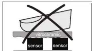
- Keep the sensor keys clean since the appliance may consider dirt to be fingering contact. Never put anything (pans, tea towels etc.) onto the sensor keys!
If food boils over onto the sensor keys, we advise you to activate the OFF key.
- Hot pans and pots should not cover resp. be moved to close to the sensor keys, since this will cause the appliance to switch off automatically.
- Place the pan as close to the centre of the cooking zone as possible.
- Whenever possible, use the back cooking zones for large pans so that the sensor keys are not heated up too much (touch control overheating; error message E2, touch control cut off).
- Activate the childproof lock if there are any pets in the home which could make contact with the hob.
The induction hob may not be used when pyrolysis operation is taking place in a built-in oven.
- Never clean the glass ceramic plate with a steam cleaner or any similar appliance!
- Make sure there are no items (e.g. cleaning cloths) right next to the hob extractor. They could be sucked in by the air current. Liquids and small items must always be kept away from the appliance.
- Do not operate the appliance without grease fi Iter.
- Filter with too much fat deposits causes fire hazard!
- Constant supervision is essential when deepfrying; fl ambéing is not permitted.
- A sufficient supply of inlet air must be provided when operating wood, coal, gas or oil heaters requiring a chimney. The permissible negative pressure which results from the hood in the location of the heaters requiring a chimney may not exceed 4 Pa (0.04 mbar) as this results in a risk of poisoning.
Vapour also emits moisture into the air in the kitchen during the cooking process.
- Only a little moisture is removed from the vapours in the convection air mode. This is why a sufficient supply of fresh air must always be provided, e.g. by opening the window or using domestic ventilation systems.
- Always make sure that the indoor climate is normal and comfortable (45 - 60 % humidity).
- Switch the hob extractor down to a lower setting for around 20 minutes or activate the automatic delayed stop function every time the hob extractor is used in the convection air mode. This is a standard function of the induction hob. See the section on "Automatic after-run".
2.3 For persons
- These appliances may be used by children aged 8 years and over and by persons with physical, sensory or mental impairments or by persons who lack experience and/or know-how, provided they are supervised or have been instructed in the safe used of the appliance and have understood the risks relating to the appliance. Children may not play with the appliance. Cleaning and maintenance by the user may only be carried out by children when they are supervised.
- The surfaces of the heating and cooking zones become hot during use. Keep small children away at all times.
- Only hob protective grids and hob covers produced by the hob manufacturer or the manufacturers of the hob protective grids and hob covers authorised by the manufacturer in the instructions for use may be used. The use of unsuitable hob protective grids and hob covers may result in accidents.
- Persons with cardiac pacemakers or implanted insulin pumps must make sure that their implants are not affected by the induction hob (the frequency range of the induction hob is 20-50 kHz). In this case, always consult your doctor/ cardiologist. He will tell you whether you are allowed to use the induction hob or not!
2.4 Explanation for symbols and indications
The appliance was produced according to state of the art technology. Machines nevertheless give rise to risks which cannot be constructively avoided.
In order to guarantee sufficient safety for the use, safety instructions are also given. These instructions are marked by way of the highlighted texts which follow.
Suffi cient safety in operation will only be guaranteed when these instructions are observed.
The designated text passages have different meanings:

DANGER
Note indicating an imminent threat which may result in death or very serious injury.

CAUTION
Note indicating a potentially dangerous situation which may result in death or very serious injury.

IMPORTANT
Note indicating a dangerous situation which may result in minor injury or damage to the appliance.

NOTE
Note to be observed in order to make handling the appliance easier.
The following danger symbols are used at some points:
WARNING OF ELECTRICAL ENERGY RISK OF FATAL INJURY!
Live components have been installed near this symbol. Covers bearing this sign may only be removed by a certifi ed skilled electrician.
CAUTION! HOT SURFACES!
This symbol has been applied to surfaces which get hot. There is a risk of serious burning or scalding. The surfaces may also be hot after the appliance has been switched off.

OBSERVE REGULATIONS FOR HANDLING ELECTROSTATICALLY SENSITIVE COMPONENTS AND MODULES (ESDS).
Electrostatically endangered components and modules are located behind covers bearing the adjacent symbol. Never touch plug connections, strip conductors or component pins. Only qualified staff members who are familiar with ESDs are authorised to carry out any technical intervention work.
3 Appliance description
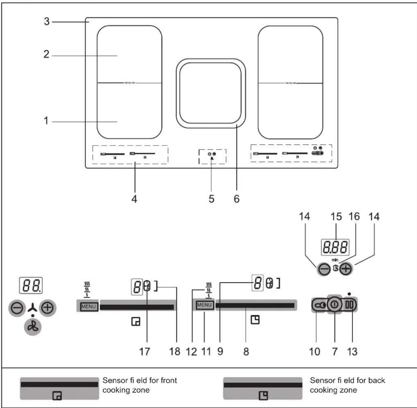
The design may deviate from the illustrations.
- Front induction cooking zone
- Rear induction cooking zone
- Glass ceramic plate
- Touch-Control panel
- Extraction control
- Extraction area
- ON/OFF key (hob)
- Slider sensor fi eld
-
Power setting display
-
Lock key
- Autoprograms key
- Display of autoprograms (3 levels)
- PAUSE key
- Minus key /Plus key Timer
- Timer indication
- Symbol egg timer
- Display cooking zone timer
- Display bridging function
3.1 Operating the hob with the sensor keys
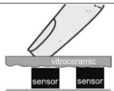
The induction hob is operated with slider touch control sensor keys. The sensor keys are operated as follows: lightly touch a symbol on the surface of the ceramic glass plate. A buzzer will indicate when the controls have been operated correctly.
The touch control sensor key will then be indicated as "key".
ON/OFF key ⑨ (7)
This key is used to switch the entire hob operational. It is, as it were, the main switch.
Power setting display (9)
The power setting indicator shows the power setting which has been selected, or:
H .Residual heat
P .Power boost
Pan recognition
Automatic boost function
11.Pause function
U....Keep-warm function
Childproof lock
Symbols
5 55 555 .......Keep-warm levels 42^ / 70^ / 94^
Timer function, automatic switch-off device
Minute minder
] .Bridging function
Lock key (10)
The lock key can be used to lock all of the keys.
Autoprograms key 1)
For melting, holding and simmering
Power boost in the sensor fi eld
The power boost setting makes additional power available for induction cooking zones.
PAUSE key (13)
The PAUSE function can be used to briefly stop the cooking process.
Recall function 13) (recovery function)
The most recent setting can be recovered if the hob is switched off unintentionally.
Fan Indication
FC Clean the grease fi Iters
Replace/regenerate the charcoal filter
Automatic delay stop deactivated
Automatic delay stop activated
Fan symbols
Extraction switched on
Extraction in automatic delay stop mode
3.2 Worth knowing about the slider (sensorfi eld)
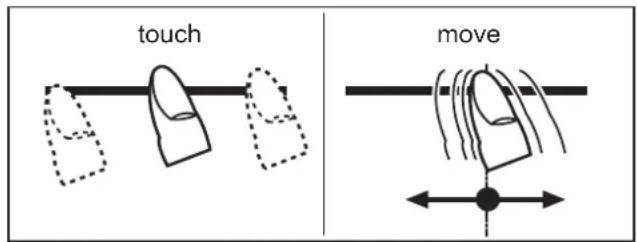
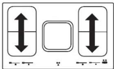
In principle, the slider functions the same as the touch controls; the only difference is that you can put your finger on the glass ceramic surface and then move it around. The sensor fi eld recognises this movement and raises or lowers the display setting (power level) in accordance with the movement.
The term sensor fi eld is used to mean slider from now on.

Sensor fi eld
What must be observed when operating sensor fi elds?
Your finger should not be placed fl at onto the glass ceramic surface in order to avoid adjacent keys/sensor fi elds from reacting by mistake.
unsuitable
right
Press the sensor fi eld lightly or move your fi nger around
You can press the sensor fi eld very lightly with your finger; when this is done the setting on the display (power level) will gradually change.
When you put your finger on the sensor fi eld and then move it to the left or right, the display setting will change progressively.
The faster the movement, the faster the change in the display.
4 Operation
4.1 The induction hob
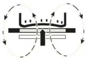
The hob is equipped with an induction cooking mode. An induction coil underneath the glass ceramic hob generates an electromagnetic alternating field which penetrates the glass ceramic and induces the heat-generating current in the pot base.
With an induction cooking zone the heat is no longer transferred from a heating element through the cooking pot into the food being cooked; instead the necessary heat is generated directly in the container by means of induction currents.
Advantages of the induction hob
- Energy-saving cooking through the direct transfer of energy to the pot (suitable pots/pans made of magnetisable material are required).
- Increased safety as the energy is only transferred when a pot is placed on the hob.
- Highly effective energy transfer between an induction cooking zone and the base of a pot.
Rapid heat-up. - The risk of burns is low as the cooking area is only heated through the pan base; food which boils over does not stick to the surface.
Rapid, sensitive control of the energy supply.
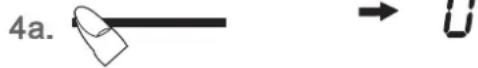
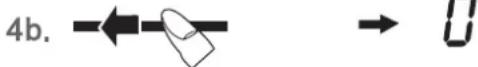
4.2 Pan recognition U
If a cooking zone is switched on and there is no pan on the zone or if the pan is too small, there will be no transmission of power. A blinking in the power level indicator points this out.
If a suitable pot or pan is placed on the cooking zone, the power setting will switch on and the power setting indicator will light up. The power supply will be cut off when the pan is removed and the power setting indicator will indicate a blinking
If the pots and pans placed on the cooking zone are of smaller dimension, and the pan recognition still switches on, less power will be supplied.
Pan recognition limits
| Cooking zone diameter (mm) | Recommended minimal diameter pan base (mm) |
| 220 x 190 115 |
The base of pots and pans must be of a certain diameter; if it is not, the induction heat will not be switched on. Always place pots and pans in the middle of a cooking zone in order to achieve the best efficiency.

NOTE
The minimum diameter required to activate the pan recognition device may vary according to the type of pot or pan used!
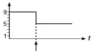
4.3 Operation time limit
The induction hob has an automatic time limit function. The duration of continuous use of each cooking zone depends on the power level selected (see chart).
This requires that the setting of a respective cooking zone is not adjusted during use.
If the operation time limit has been activated, the cooking zone will switch off, a short signal will sound and an H will appear in the display.
The automatic switch-off function overrules the operation time limit, i.e. the cooking zone is only switched off when the period of time of the automatic switch-off device has expired (e.g. automatic switch-off after 99 minutes and cooking level 9 is possible).
Operation time limit
| Selected power level | Operation time limit in minutes |
| S S S S S U | 120 |
| 1 | 520 |
| 2 | 402 |
| 3 | 318 |
| 4 | 260 |
| 5 | 212 |
| 6 | 170 |
| 7 | 139 |
| 8 | 113 |
| 9 | 90 |
| P | 10 |
4.4 Other functions
If two or more sensor keys are pressed at the same time (e.g. when a pan is mistakenly put onto a sensor key) no function will be activated.
The symbol will blink and a time-limited continuous signal will sound. After a few seconds the appliance will switch off. Please remove the item located in front of the sensor keys.
To delete the symbol, press the same key or switch the hob off and on.
4.5 Protection against overheating (induction)
If the hob is used at full power for a longer period, it will not be possible to cool down the electronics system as required at a high room temperature.
In order to ensure that no excessive temperatures occur in the electronics system the power of the cooking zones may be reduced automatically. Should E2 be displayed frequently during normal use of the hob and at normal room temperature, it is likely that cooling is not sufficient.
This may occur if kitchen units have no openings. The installation may have to be checked (see the section on Ventilation).
4.6 Cookware for induction hobs
Cookware for induction cooking zones must be made of metal and have magnetic properties. The base must be sufficiently large.
Only use pots with a base suitable for induction.
| Suitable cookware Unsuitable cookware | |
| Enamelled steel pots with a thick base | Pots made of copper, stainless steel, aluminium, oven-proof glass, wood, ceramic and terracotta |
| Cast iron pots with an enamelled base | |
| Pots made of multi-layer stainless steel, stainless ferrite steel and aluminium with special base | |
This is how to establish the suitability of a pot:
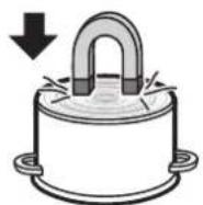
Conduct the magnet test described below or make sure that the pot bears the symbol for suitability for cooking with induction current.
Magnet test:
Move the magnet towards the base of your cookware. If it is attracted, you can use the cookware on the induction hob.
NOTE
When using pans suitable for induction from certain manufacturers, noises may occur which are attributable to the design of these pans.
Wrong: the base of the pan is curved. The electronic unit cannot determine the temperature correctly.
4.7 How to cut power consumption
The following are a few useful hints to help you cut your consumption of energy and use your new induction hob and the cookware effi ciently.
- The base of your cooking pots should be the same size as the cooking zone.
- When buying cooking pots, note that it is frequently the diameter of the top of the pot that it indicated. This is usually larger than the base of a pot.
- Pressure cookers are particularly low on energy and time required thanks to the pressure and the fact that they are tightly closed. Short cooking times mean that vitamins are preserved.
Always make sure that there is suffi cients in your pressure cooker since the cooking zone and the cooker may be damaged as a result of overheating if the pressure cooker boils dry. - Always close cooking pots with a suitable lid.
- Use the right pot for the quantity of food you are cooking. A large pot which is hardly filled will use up a lot of energy.
4.8 Power levels
The heating power of the cooking zones can be set at various power levels. In the chart you will find examples of how to use each setting.
| Power level | Suitable for |
| 0 | Off, using residual heat |
| U | Melting 42°C |
| U | Keeping warm 570°C |
| U | Cooking 594°C |
| 1-2 | Simmering small portions |
| 3 | Simmering level |
| 4-5 | Simmering larger quantities or roasting larger pieces of meat until they are cooked through |
| 6 | Roasting, getting juices |
| 7-8 | Roasting |
| 9 | Bringing to the boil, browning, roasting |
| P | Power boost (highest power output) |
A higher power level may need to be selected for cooking pots without a lid.
4.9 Residual heat display H
The glass ceramic hob is equipped with an H as a residual heat indicator. As long as the H lights up after the cooking zone has been switched off, the residual heat can be used for melting food or for keeping food warm.

CAUTION
The cooking zone may still be hot when the letter H no longer lights up. Risk of burns!
The glass ceramic is not directly heated in the case of an induction cooking zone; it is only heated up by heat reflected by the pan.
4.10 Operating the keys
In the procedure described below, the following key must be activated within 10 seconds. If this is not the case, a selection is no longer possible.

Suitable for induction cooking
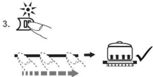
4.11 Switching on the induction hob and cooking zone
- Press the ON/OFF key (approx. 1 sec.) until the power setting 0 appears and a short signal will sound. The controls are ready for operation.
- The sensor fi eld-of a cooking zone must be activated immediately afterwards. A power setting will be switched on.
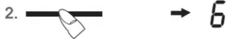
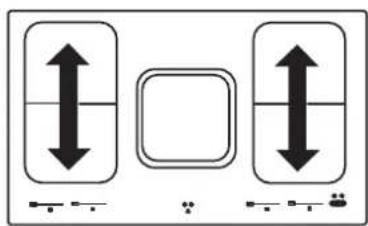
left Power setting 0. center Power setting 6. right Power setting P*
See the section on Worth knowing about the slider (sensor fi eld)
Press the respective sensor fi eld-to change a power setting or to switch on an additional cooking zone.
- Immediately put cookware suitable for induction cooking onto the cooking zone. The pan recognition device will activate the induction coil. The pot or pan will be heated up.
As long as no cooking pot is placed onto the cooking zone, the display will alternate between the power level set and the symbol for "No pot detected". If no pot is placed on the cooking zone it will switch off after 10 minutes for reasons of safety. Please refer to the Section on pan recognition.

4.12 Switching off a cooking zone
- a) Press the sensor fi eld on the far left b) drag your finger to the left across the touch control to reduce the power setting to 0
c) press the ON/OFF key @All the cooking zones are switched off.
4.13 Switching off the induction hob
- Press the ON/OFF key The induction hob will be switched off, irrespective of any settings.

NOTE
The hob will switch off automatically after 10 seconds when all the cooking zones are switched of manually (power setting 0) and no key/sensor fi eld is pressed afterwards.
- The Power boost function is activated immediately.
See the section on Power setting.
4.14 PAUSE function
The cooking process can be briefly interrupted with the PAUSE function, e.g. if the doorbell rings. The PAUSE function must be released in order to continue cooking at the same power level. If a timer has been set it will pause and will then continue.
This function is only available for 10 minutes for reasons of safety. The hob will then be switched off.
- Pots and pans are on the cooking zones and the required power levels have been set.
- Press the PAUSE key. Instead of the selected power settings, the interval sign will light up.
- The interruption is ended by firstly pressing the PAUSE key and then the flashing sensor fi eld left of the PAUSE key.
When operating the sensor fi eld slide over the complete sensor fi eld.
The second key must be pressed within 10 seconds, otherwise the Pause function will be maintained.
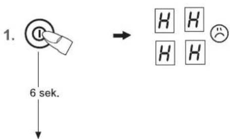
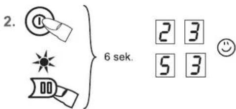
4.15 Recall function
(recovery function)
The most recent setting can be recovered if the hob is switched off unintentionally.
The recall function only works if at least one cooking zone is switched on.
- The hob is inadvertently turned off by the ON/OFF key of the hob
- Within 6 seconds after turning it off, press the ON/OFF key of the hob again. The PAUSE key LED will blink. The PAUSE key must be pressed immediately afterwards.
The original cooking levels are restored. The cooking process continues.
What can be restored:
- Cooking levels of all cooking zones
- Minutes and seconds of programmed timer functions
Automatic boost function
Power boost
Not to be restored:
Operation time limit (it is counted from 0)
- L
-
B X
- 1 + →5
3.
4.16 Childproof lock
The childproof lock serves the purpose of preventing children from switching on the induction hob either accidentally or intentionally. The controls are blocked here.
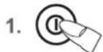
Switching on the childproof lock
- Press the ON/OFF key of the hob (approx. 1 sec.) in order to switch the entire hob on.
- Immediately afterwards press the Lock key 忍 and the PAUSE key simultaneously.
- Then press the Lock key in order to activate the childproof lock. The power setting indicators will show an L for child lock, the controls will be disabled and the hob will switch off.
Switching off the childproof lock
- Press the ON/OFF key 9
- Immediately afterwards press the Lock key and the PAUSE key simultaneously.
- Then press the PAUSE key in order to deactivate the childproof lock. The L will go off.
De-activating the childproof lock for one cooking procedure only
This is only possible if the childproof lock has been switched on according to points 1-3.
Press the ON/OFF key.
- Immediately afterwards press the Lock key and the PAUSE key simultaneously. Now the user will be able to switch on a cooking zone. When the hob is switched off the childproof lock will be activated again (switched on).
Notes
- In the event of a power cut the childproof lock will be cancelled, i.e. deactivated.
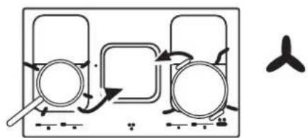
4.17 Bridging function
The front and the rear cooking zones may be activated together for a cooking process (bridging function). This enables larger cookware to be used.
- Switch on the induction hob.
- Press the sensor fi eld of the rear and front cooking zones simultaneously to activate the bridging function. The bridging function is activated, the symbol ] appears. Operation is carried out with the sensor fi eld of the front cooking zone.
- To deactivate the two sensor fields—press them simultaneously again or switch off the induction hob.
NOTE
The roaster or the pot will need to cover at least half of the cooking zones used in order to be recognised by the pan recognition device!
4.18 Automatic switch-off (timer)
The automatic switch-off device is used to automatically switch off any cooking zone after an adjustable period of time. Cooking times ranging from 10 seconds (0.10) to 1 hour and 59 minutes (1.59) can be set.
- 1x,2x,3x..
- ④ → 1.15
-
Switch on the induction hob. Switch on one or more cooking zones and select the required power settings.
- Press the Plus and Minus key simultaneously until the symbol for the desired cooking zone lights up.
- To set the time press the Plus- or Minus key. After a few seconds your input will be assumed and the procedure will have commenced. The decimal point will blink.
- The cooking zone will be switched off when the time has lapsed. A buzzer will sound temporarily and can be switched off by pressing the Plus key and the Minus key
Notes
- Repeat steps 2 to 3 to program the automatic switch-off device for another cooking zone.
To check the time that has lapsed (automatic switch-off) push the Plus- and Minus key simultaneously until the symbol for the desired cooking zone lights up. The setting displayed can be read and changed.
Terminating the function of the timer: select the cooking zone by pressing the Plus- and Minus keys simultaneously and press the Minus key to delete the time (0). -
If several cooking zones have been programmed with the automatic switch-off function, the timer display will always show the cooking zone with the shortest time.
- 1x,2x,3x..
- 500
- ④
4.19 Minute minder (egg timer)
The cooking zones are switched off.
- Switch on the induction hob.
- Press the Plus- and Minus keys simultaneously until the symbol under the timer display lights up.
- To set the time press the Plus- or Minus key. After a few seconds your input will be assumed and the procedure will have commenced. The decimal point will blink.
- A buzzer will sound temporarily and can be switched off by pressing the Plus or the Minus key
Setting timer if cooking zones are in operation
- Press the Plus- and Minus keys simultaneously until the symbol under the timer display lights up.
To set the time press the Plus- Minus key. - A buzzer will sound temporarily and can be switched off by pressing the Plus or the Minus key.

NOTE
The minute minder will also remain in operation when the right or left side of the hob is switched off. Switch the left or right side of the hob on to adjust the time.
Press and keep pressed (for approx. 3 seconds)

| Cooking level Power level | Automatic boost function Time (min:sec) |
| 1 | 0:40 |
| 2 | 01:12 |
| 3 | 02:00 |
| 4 | 02:56 |
| 5 | 04:16 |
| 6 | 07:12 |
| 7 | 02:00 |
| 8 | 03:12 |
| 9 | - |
4.20 Automatic boost function
Food is parboiled at power level 9 with the automatic boost function. After a certain time, the power level will switch down automatically to a lower simmering setting (1 to 8).
When using the automatic boost function only the simmering setting with which the food is to be cooked through needs to be selected since the electronic unit switches down automatically.
The automatic boost function is suitable for dishes which are cold initially and are then heated up at high power. These dishes do not need to be constantly monitored when simmering (e.g. boiling meat for soups).
- Switch on the induction hob.
- Press the sensor fi eld- and keep it pressed (for approx. 3 seconds) to activate the function and immediately select a specific simmering setting: left Setting 1 center Setting 6 right Setting 8 A and the selected simmering setting will blink alternately.
- The automatic boost function will operate as programmed. After a certain time (see chart) the cooking process will be continued with the simmering setting. The A symbol will go off.

NOTE
- The simmering setting can be raised while the automatic boost function is in operation. A reduction in the simmering setting will switch off the automatic boost function.
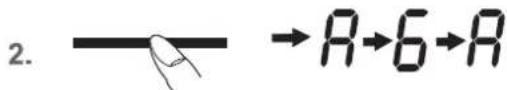
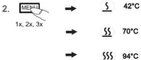
4.21 Keep-warm function
With the keep-warm function you keep food warm with a specific temperature. In this mode, the cooking zone consumes little power.
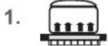
- Cookware is placed on a cooking zone and a power level (e.g. 3) is selected.
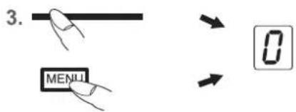
- By repeatedly pressing the Keep warm key select the setting: corresponds to about 42^ corresponds to about 70^ corresponds to about 94^
- To switch off the function press the sensor fi eld on the far left or press the Warming key
The keep-warm function is available for 120 minutes, after which the cooking zone will be switched off.
- →
2.
4.22 Locking
The lock can be used to lock key operation and cooking level settings. Only the ON/OFF key can be used to switch the hob off.
Activating the lock
- Press the lock key The control lamp above the Lock key will light up.
Switching off the lock
- Press the lock key 品 . The control lamp above the Lock key will light up.

NOTES
An activated lock will remain activated even if the induction hob is switched off. It must therefore be deactivated when cooking is re-commenced. In the event of a power cut the lock will be cancelled, i.e. deactivated.
1.
4.23 Power boost
The power boost setting makes additional power available for induction cooking zones. A large quantity of water can be brought to the boil very quickly.
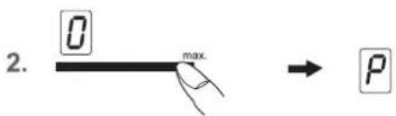
- Switch on the induction hob.
- Press the respective sensor fi eld on the far right on MAX of the respective cooking zone. The power setting display shows PThe power boost will now be activated.
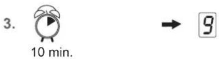
- After 10 minutes the power boost setting will switch off automatically. The will go off and the power level will switch down to 9.
NOTE
Press the respective sensor fi eld to prematurely switch off the power boost setting.
Modules (power management)
4.24 Power management
For technical reasons two cooking zones always comprise a module and have a maximum power level. If this power range is exceeded when a higher power setting level or the power boost function is switched on the power management system will reduce the power setting of the corresponding cooking zone of the module. The display for this cooking zone will initially blink, after which the highest-possible power setting will be consistently displayed.
1.


2.


3.


.

2.

3.
4.25 Use extraction system
The suction is located in the middle of the hob with the extractor facing downwards.

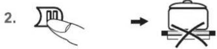
IMPORTANT
Do not place the lid on the induction hob! Risk of burning!
4.25.1 Switching the fan on and off
- Press the fan ON/OFF key approx. 1 s.)
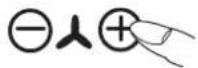
- You will then be able to select a power setting, 1,2,3 or 4, by using the Plus Minus key .The symbol for the fan will light up.
The intensive power setting P operates for 10 minutes, after which the power level is automatically reduced to power setting 4.
- Press the fan Minus key until 0 is shown or press the ON/Off key of the fan in order to switch fan off.
Hint
In order to ensure that extraction functions well with tall cooking pots (e.g. pots used for cooking asparagus), you can place a wooden spoon under the lid of the pot.
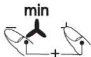
4.25.2 Adjustable after-run of the extraction system
The exhaust after-run is used after cooking to eliminate cooking odours. The fi iters are also dried in the system.
Adjusting the after-run of the extraction system
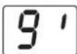
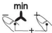
- Press simultaneously the extractor Plus key and Minus key The after-run of the extractor of 10 minutes will be activated. The fan symbol and the decimal point blink.
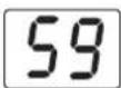
- Pressing the plus key will raise the time in 5-minutes steps.
Pressing the minus key will lower the time in 5-minutes steps.
- Pressing simultaneously again the Plus- and Minus key will start the settings; the display will go off. The remaining run time and set fan speed is displayed for a short time every 30 seconds.
Changing the after-run time of the extraction system
- Press simultaneously the extractor Plus key and Minus key in order to change the time.
Cutting off the after-run of the extraction system
- Press the ON/Off key of the extractor

NOTE
If the extraction system has been in operation for at least 15 minutes, an automatic after-run of 15 minutes at level 1 runs to dry out the system.
Disable automatic after-run
- Turning on the control via the on/off switch on the fan
- Press the on/off button on the fan for approximately 3 seconds until displayed. The automatic fan is permanently disabled.
- Turning on the control via the on/off switch on the fan
- Press the on/off button on the fan for approximately 3 seconds until is displayed. The automatic fan run is permanently activated.
4.25.3 Notes on runtime
The fan motor should continue operating for another 10-20 minutes every time the hob has been used for cooking. When the fan is switched off after having been in operation for at least 15 minutes, an automatic time lag at a low setting will follow for around 15 minutes.
This guarantees optimal functioning and the removal of remaining cooking steam.
When using a recirculating air fi liter, please always allow for a stop delay time of 10 - 60 minutes in order to optimally remove cooking odours.
When the fan is switched on again, in rare cases the odour molecules present in the fiiter may be combined with steam so that they are detected again. These remaining odours will disappear when the fan continues to operate.

IMPORTANT
When the recirculation mode is in operation, ventilation must be sufficient in order for the air humidity to be removed.
4.25.4 Indication: Clean the grease fi Iters
After 10 hours of operation the display for fi liter cleaning appears. The grease fi liter must be cleaned, otherwise there is a risk of fire.
To continue to use the ventilation, confirm the display with the Minus key
If the grease filter has been cleaned, you can delete the display by pressing the Minus key and the ON/OFF key on the extractor at the same time for at least 3 seconds. The counter for the display starts again at 0 hours.
4.25.5 Indication: Replace the charcoal fi Iter[
After 150 hours of operation the display for Carbon Cleaning appears [The charcoal filter needs to be replaced.
To continue to use the ventilation, confirm the display using the Plus key to
If the carbon filter has been replaced, you can delete the display by pressing the Plus key and the ON/OFF key on the extractor at the same time for at least 3 seconds. The counter for the display starts again at 0 hours.
4.25.6 Turn off the carbon filter operating hours counter during the operation of the air exhaust
During the operation of the air exhaust, the operating hours counter for the carbon filter must be turned off.
To do this, the control panel must first be turned on using the ON/OFF key of the fan and there may not be any messages displayed.
Then simultaneously press the Plus key and the ON/OFF key from the fan 3 seconds.
The display will show (carbon off) and the operating hours counter for the charcoal filter is turned off.
To turn the operating hours counter back on, repeat the operation.
The display will show (carbon on) and the operating hours counter for the charcoal fiiter is now turned on.
5 Cleaning and care
- Switch the induction hob off and let it cool down before you clean it.
- Never clean the glass ceramic plate with a steam cleaner or any similar appliance!
- When cleaning make sure that you only wipe lightly over the ON/OFF key. The hob may otherwise be accidentally switched on!
5.1 Glass ceramic plate
IMPORTANT
Never use aggressive cleaning agents such as rough scouring agent, abrasive saucepan cleaners, rust and stain removers etc.
Cleaning after use
- Always clean the entire induction hob when it has become soiled. It is recommended that you do so every time the hob is used. Use a damp cloth and a little washing up liquid for cleaning. Then dry the glass ceramic plate with a clean dry cloth to ensure that there is no detergent left on the surface of the hob.
Weekly cleaning
- Clean the entire induction hob thoroughly once a week with commercial glass ceramic cleaning agents. Please follow the manufacturer's instructions carefully. When applied, the cleaning agent will coat the hob in a protective fi lm which is resistant to water and dirt. All the dirt will remain on the fi lm and can then easily be removed. Then rub the hob dry with a clean cloth. Make sure that no cleaning agent remains on the surface of the hob since this will react aggressively when the hob is heated up and will change the surface.
Heavy soiling and stains (limescaling and shiny, mother
of-pearl-type stains) can best be removed when the induction hob is still slightly warm. Use commercial cleaning agents to clean the hob. Proceed as outlined under Item 2.
First soak food which has boiled over with a wet cloth and then remove remaining soiling with a special glass scraper for glass ceramic clean the hob again as described u
Burnt sugar and melted plastic must be removed immediately, when they are still hot, with a glass scraper. Then clean the glass ceramic plate again as described under Item 2.
Grains of sand which may get onto the hob when you peel potatoes or clean lettuce may scratch the surface of the hob when you move pots around. Make sure that no grains of sand are left on the hob.
Changes to the colour of the ceramic surface have no effect on the function and stability of the glass ceramic. These colour changes are not changes in the material but food residues which were not removed and which have burnt into the surface.
Shining areas are caused by wear from pan bottoms or unsuitable cleaning agents, especially when using cookware with aluminium bases or by unsuitable cleaning agents. They are difficult to remove with standard cleaning agents. You may need to repeat the cleaning process several times. In time, the design will wear off and dark stains will appear as a result of using aggressive cleaning agents and faulty pan bases.
5.2 Extraction
Cleaning the grease fi iters
Clean the grease fi Iter in the dishwasher or in mild soapy water at least once a month or in the event of excessive grease deposits and/or intensive use.
Lift the extraction hood before removing the fi iter. This makes it easy to remove the fi iter for cleaning.


NOTE
Do not place the glass cover too firmly. Risk of glass breakage.
The fi Itter can be rinsed in a dishwasher. Turning the fi Itters in the dishwasher upside down. Please use only rinse aid that is suitable for RVS use with aluminium in order to avoid damaging and discolouring the fi Itters.
Never rinse right next to glasses or light-coloured porcelain.
Do not operate the extractor without grease fi Iters!
After rinsing the fi liter, dry it and replace it in the extractor. Please make sure that the recessed handle is visible after you have replaced the fi liter. If possible, wipe the easily accessible inside of the extractor with a cloth dampened with detergent every time you replace a fi liter, while at the same time paying attention to protruding parts in the inside of the extractor.
Cleaning and care of the extraction housing
The extraction housing is best cleaned every time you clean the filters.
Condensation water may collect under the extraction housing after water has boiled rapidly with the lid of the pot removed. This is quite normal. The water should, however, be removed and the inside of the extraction housing cleaned.
Failure to clean the grease fiiter and the housing in good time can lead to unpleasant odours at rest and at the beginning of the extraction process. It is therefore advisable to carry out this cleaning at least once a month. It is best to clean the housing with a damp, soft cloth and mild detergent solution.
Service
The recirculating air fi ler must remain accessible. Replace the charcoal fi ler mats of a charcoal fi ler every 5 to 24 months. This strongly depends on the cooking behaviour of the user (intensity and regularity).
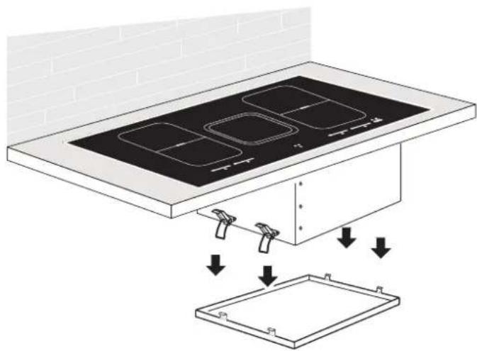
Removable bottom
The bottom can be removed for cleaning.
Switch off the hob and extractor and remove the glass cover and the fi filter.
Hold the bottom firmly with one hand from below and open the 4 locks with the other hand. After opening, hold the bottom horizontally and carefully remove it downwards.
Drain any liquids and thoroughly remove any impurities. Clean the accessible inside of the housing. Optionally, the bottom can be cleaned in the dishwasher.
It must be reset in place after cleaning and attached with the 4 closures.
6 What to do if trouble occurs?
Interference with and repairs to the appliance by unqualified persons are dangerous as they can result in an electric shock or a short circuit. Do not interfere with or try to repair the appliance; this could cause injury to persons and damage to the appliance. Always have such work done by an expert, e.g. a Customer Service technician.
Please note
If your appliance is faulty, please check whether you can rectify the problem yourself by consulting these instructions for use.
You may be able to rectify some problems yourself. They are described below.
The fuses blow regularly?
Contact a technical customer service or a service technician!
You can't switch your induction hob on?
- Has the wiring system (fuse box) in the house blown a fuse?
- Has the hob been connected to the mains?
Is the childproof lock activated, i.e. does the display show an "L"? - Are the sensor keys partly covered by a damp cloth, fluid or a metallic object? Please rectify.
- Are you using unsuitable cookware? See the section on Cookware for induction hobs.
The symbol r^j will blink and a time-limited continuous signal will sound.
Food which has boiled over, cookware or other items are causing the touch control sensor keys to be consistently operated.
Remedy: clean the surface or remove the item. To delete the symbol press the same key or switch the induction hob off and on.
Error code E2 is indicated?
The electronic unit is too hot. Check the installation of the induction hob. Make sure that there is sufficient ventilation.
See the section on "Protection against overheating". See the section on "Ventilation".
Error code E8 is indicated?
Fault on the left or right fan. The suction opening is blocked or covered or the fan is defect.
Check the installation of the hob. Make sure that there is sufficient ventilation.
See the section on "Protection against overheating". See the section on "Ventilation".
Error code U400 is indicated?
The hob has been incorrectly connected. The controls will switch off after 1s and a continuous signal will sound. Connect the appliance to the appropriate power supply.
An error code (ERxx or Ex) is indicated?
The appliance has developed a technical defect. Please call Customer Service.
The pot sign appears?
A cooking zone has been switched on and the hob is expecting a suitable pot or pan to be placed on the cooking zone (pan recognition). Only when a pot has been placed on the cooking zone will power be supplied.
The pot sign still appears, even though a pot or pan was placed on the hob?
The cookware is unsuitable for induction cooking or the pot or pan is too small.
Is the cookware you are using making noises?
This is due to technical reasons; the induction hob and the pot are not at risk.
Does the cooling fan still operate after it has been switched off?
This is normal since the electronic unit is being cooled down.
Is the hob making noises (clicking or cracking sounds)?
This is for technical reasons and cannot be avoided.
Does the hob have tears or cracks?
There is a risk of electric shocks if the glass ceramic plate develops fractures, cracks, tears or damage of any other kind. Immediately switch off the appliance. Disconnect the fuse immediately and call Customer Service.
7 Instructions for assembly
7.1 Safety instructions for kitchen unit fi tters
Veneers, adhesives and plastic surfaces of surrounding furniture must be temperature resistant (at least 75^ ). If the veneers and surfaces are not sufficiently heat resistant they may become deformed.
- Ensure that all live connections are safely insulated when installing the hob.
- Cover strips between the wall and the worktop behind the hob which are made of solid wood are permissible as long as minimum clearances in accordance with the installation diagrams are maintained.
- Minimum clearances of the hob cut-out towards the rear are to be maintained in accordance with the installation diagram.
- For installation directly next to a tall cupboard, a safety distance of at least 50~mm must be ensured. The side surface of the tall cupboard should be fitted with heat resistant material. Due to working requirements, however, the distance should be at least 300~mm .
- The packaging materials (plastic foil, polystyrene, nails etc.) must be kept out of reach of children as these parts are potentially dangerous. Small parts can be swallowed and there is a danger of plastic sheeting causing suffocation.
7.2 Ventilation
- The induction hob is fitted with a fan that switches on and off automatically. The fan starts slowly when the electronic system temperatures exceed a specific limit. When the induction hob is used intensively, the fan will switch to a greater velocity. Once the electronic system has cooled down sufficiently, the fan will reduce its velocity and switch off again automatically.
- Clearance between the induction hob and kitchen furniture or built-in units must provide for sufficient ventilation of the induction hob.
- If the power level of a cooking zone is automatically raised or lowered (see section on thermal cut-off device) it is likely that the cooling system does not cool sufficiently. In this case we recommend that the back wall of the bottom kitchen unit in the area of the worktop cut-out be opened and that the front transverse strip of the unit be removed over the entire width of the appliance in order to promote the circulation of air.
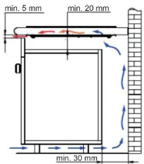
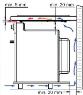
In order to better ventilate the hob, an air gap of 5mm should be left at the front.
7.3 Installation
Important information
- Remove any transverse strips underneath the worktop at least in the area of the worktop cut-out.
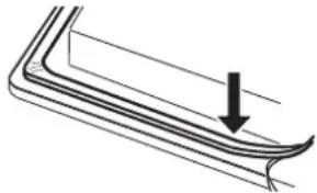
Sealing of the hob
Before installation, correctly insert the sealing unit delivered with the hob.
- No liquids may penetrate between the edge of the hob and the worktop or between the hob and the wall and come into contact with any electrical appliances.
- When installing a hob into an uneven worktop, e.g. with a ceramic or similar covering (tiles etc.), the seal on the hob is to be removed and the seal between the hob and worktop made with plastic sealing materials (putty).
- The hob must under no circumstances be sealed with silicone sealant! This would make it impossible to remove the hob at a later date without damaging it.
Worktop cut-out
Cut out the worktop recess accurately with a good, straight saw blade or recessing machine. The cut edges should then be sealed so that no moisture can penetrate. The area is cut out as illustrated. The induction surface must have a level and fl ush bearing. Any distortion may lead to fracture of the glass panel. Make sure that the sealing of the hob is properly seated.
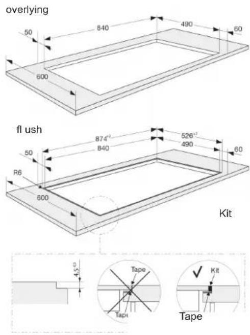
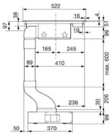
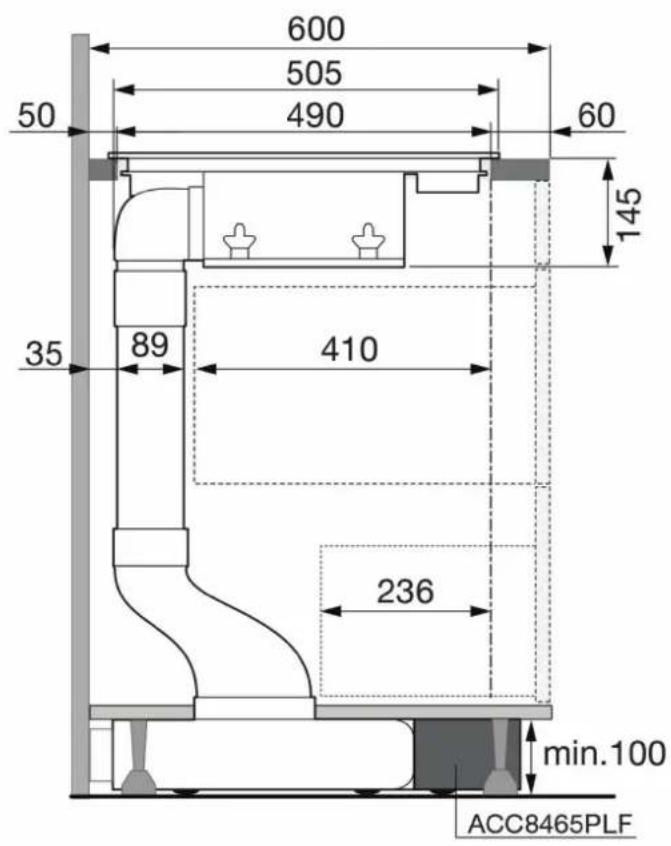
7.4 Variable installation possibilities: Overlying installation
Dimensions in mm

NOTE
There is a risk of breakage if the induction hob is canted or subjected to stress during installation!
Flush installation
Glue the sealing tape onto the corner of the supporting edge of the worktop so that no silicone adhesive can be pressed under the hob. Place the hob into the worktop cut-out without any adhesive and align it. Use shims if necessary. Fill the gap between the hob and the worktop with heat-resistant silicone adhesive.
Important
Silicone adhesive must not get under the support surface of the hob. If this occurs it will not be possible to remove the hob again at a later stage. No liability will be assumed in the case of failure to observe these instructions.
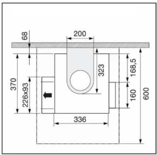
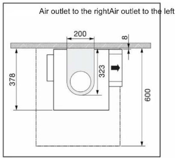
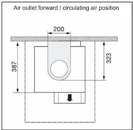
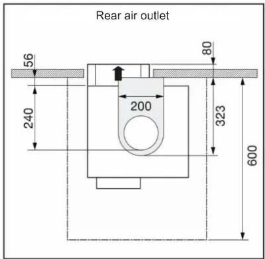
7.5 External dimensions
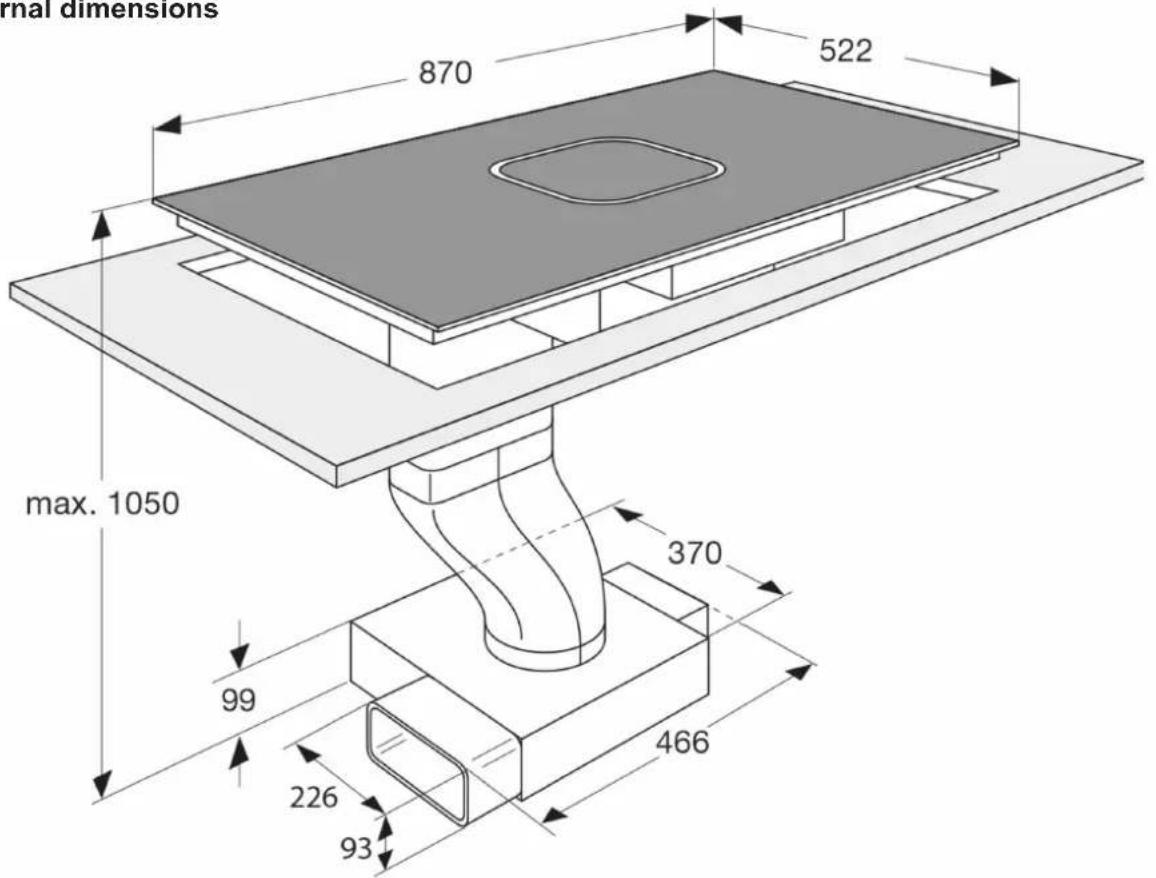
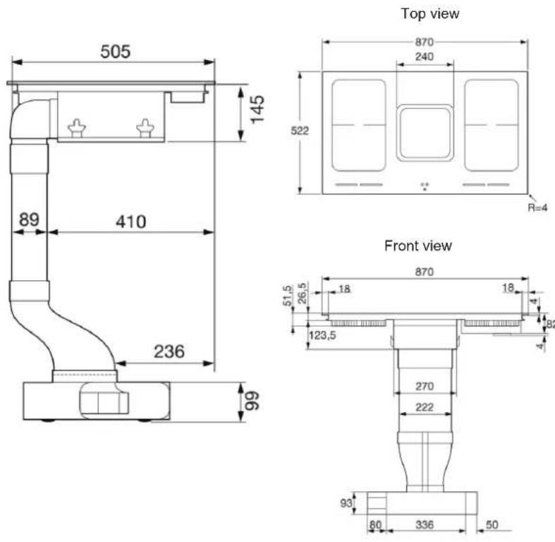
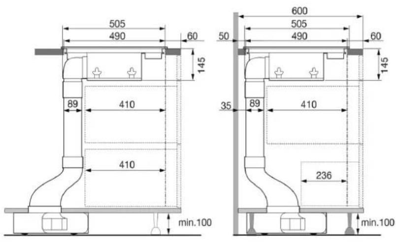
Island installation Wall installation
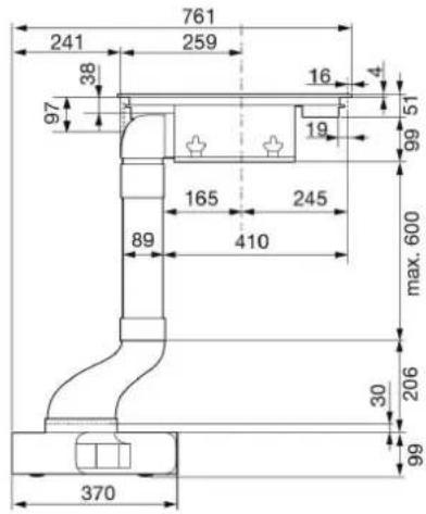
Island installation Wall installation
Installation for recirculation air mode
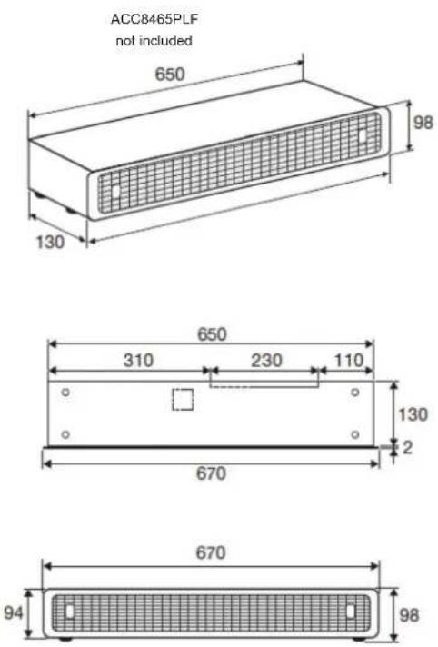
Info
Power: 200 W
Cable length: 1.85m
Standard 90 degree plug with earthing
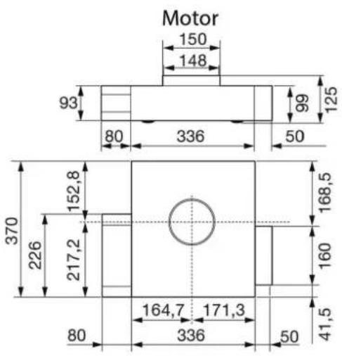
7.6 Installation of the extraction system
- The product may only be connected by a quali ed fi tter according to applicable local regulations. The same applies for the extraction air connections. The fi tter is responsible for proper functioning at the installation site.
- On installation, observe the relevant national building regulations and the regulations of the electricity suppliers.
- The hob extractor can be operated in the extraction air and recirculation air mode.
- Lead the outgoing air outside through a ventilation shaft intended for this purpose or through the wall of the building.
- Outgoing air may not be led into a smoke or exhaust gas flue which is in operation. Contact the district master chimney sweep if you are in any doubt.
- A suffi cient supply of inlet air must be provided if a wood, coal, gas or oil heater requiring a chimney is operated in the environment of the hob fan, since an insufficient supply of air results in a risk of poisoning. The safe operation of the hob extractor is guaranteed when the negative pressure resulting from the hob extractor does not exceed 0.04 mbar (4 Pa) and a sufficient supply of inlet air can flow into the room.
- Exhaust air pipes must comply with fire class B 1 DIN 4102.
- Please make sure that the minimum nominal width of the appliance connecting pieces is not reduced.
- A system recommended for the airflow and compatible with the hob extractor should always be used.
-
The nominal width of the recirculation air pipe should not be less than 150~mm .
-
Exhaust air pipes should be as short as possible. They should not have a 90-degree angle; instead they should have soft bends and no reductions in their cross-section.
- Never use pipes with a diameter of less than 150~mm .
- Always insert a straight piece of approx. 50 cm between two angles/bends.
- The cross-section of wall vents and the cut-out in the base panel should should at least correspond to the exhaust air pipe. The outflow opening must be at least 500~cm^2 . Reduce the height of the skirting boards or make corresponding openings.
- When installing the appliance make sure that the convection air unit is still accessible when the kitchen has been completely installed.
- If necessary levelling feet for the kitchen units must be moved. This depends on the kitchen system. If you have any questions, contact your kitchen supplier.

NOTE
When the convection air mode is in operation, ventilation must be sufficient in order for the air humidity to be removed.
7.7 Electrical connection
WARNING OF ELECTRICAL ENERGY! RISK OF FATAL INJURY!
Live components have been installed near this symbol. Covers bearing this sign may only be removed by a certifi ed skilled electrician.
- The electrical connection must be carried out by a qualifi ed electrician who is authorised to carry out such work!
Statutory regulations and the connection specific cations issued by the local power supply company must be strictly observed. - When connecting the appliance it must be ensured that there is a device which makes it possible to universally disconnect it from the mains with a contact opening width of at least 3mm . Line-protecting switches, fuses or contactors are suitable cut-out devices. When connecting and repairing the appliance disconnect it from the electricity supply with one of these devices.
- The earth wire must be sufficiently long so that if the strain relief fails, the live wires of the connecting cable are subjected to tension before the earth wire.
- Any superfluous cable must be removed from the installation area beneath the appliance.
- Make sure that the local mains voltage is the same as the voltage on the rating label.
Full protection against accidental contact must be ensured on installation. - Attention: Incorrect connection may result in the power electronics unit being destroyed.
- The appliance is only authorised for permanent connection. It may not be connected with a shockproof plug.
Connected loads of the induction hob
380-415 2N 50/60Hz and 220-240 2N 50/60Hz
7400W
Component rated voltage: 220-240V
Connected loads of the extraction motor
220-240V 50/60Hz
168W
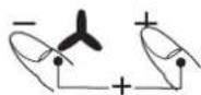
Induction connection
- There is no standard cable available for connecting the induction part.
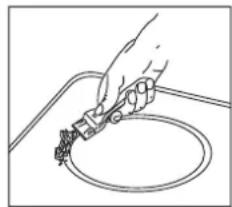
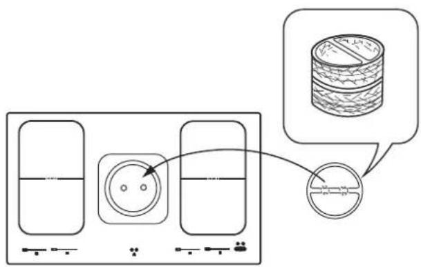
- To connect the appliance, unscrew the cover of the connection socket on the underside of the appliance in order to be able to access the terminal. After connecting the appliance, replace the cover and secure the connection cable with the strain relief clamp.
The connection cable must be at least H05 RR-F.
| 220-240 V 50/60 Hz | |
| 1 2 3 4 5 L1 N PE L1 220-240V L2 1N 220-240 V 50/60 Hz | 1 2 3 4 5 L1 L2 N PE L2 220-240V L2 220-240V L3 has no load |
| 1 2 3 4 5 L1 N PE L1 220-240V L2 220-240V L3 has no load | 1 2 3 4 5 L1 L2 N PE L2 220-240V L2 220-240V L3 has no load |
7.8 Putting the appliance into operation
Once the hob has been installed and the power supply has been provided (mains connected) an automatic test of the controls will be carried out and information for Customer Service will be indicated.
Important: No items may be on the touch control sensor keys when the appliance is being connected!
8 Technical Data
| Hob dimensions height/ width/ depth . mm 150 x 870 x 522 |
| Cooking zones all zones ............ cm / kW 19x22/ 2,1 (3,7)* |
| Hob ............ kW 7.4 |
| Extractor ............ kW 0.168 |
- Power when the power boost function is activated
9 Efficienl Measurement Data Sheet
| Regulation (EU) 66/2014 | ||
| Brand ATAG | ||
| Model / Type HIDD8471LV | HIDD8472LV | |
| Hob type Built-in hob | ||
| Number of cooking zones and/or surfaces 4 | ||
| Heating technology Induction cooking zones | ||
| Non-round cooking zone I (LxW) cm 19x22 | ||
| Non-round cooking zone II (LxW) cm 19x22 | ||
| Non-round cooking zone III (LxW) cm 19x22 | ||
| Non-round cooking zone IV (LxW) cm 19x22 | ||
| Energy absorption cooking zone I per kg kWh/kg 190.4 | ||
| Energy absorption cooking zone II per kg | kWh/kg 166.2 | |
| Energy absorption cooking zone III per kg | kWh/kg 190.4 | |
| Energy absorption cooking zone IV per kg | kWh/kg 166.2 | |
| Energy absorption cooking zone per kg | kWh/kg 178.3 |
10 ECO data information
| Model | HIDD8471LV / HIDD8472LV | |||||
| Type | Induction hob with integrated extractor | |||||
| Operation | Touch Control | |||||
| Air duct | Recirculation air | |||||
| m3/h | dB | Pa | m3/h | dB | Pa | |
| Level 1 | 94.6 | 31 | 1 | 51.7 | 30 | 0 |
| Level 2 | 189.9 | 47.5 | 5 | 122.3 | 46 | 0 |
| Level 3 | 322.3 | 60 | 13 | 220.4 | 59 | 0 |
| Level 4 | 455.7 | 68 | 26 | 319.5 | 66 | 0 |
| Setting P | 541.8 | 72 | 37 | 397.2 | 71 | 0 |
11 Decommissioning and disposal of the appliance
11.1 Switching the appliance off completely
The appliance is to be put out of operation when its useful life has finally come to an end.
- Disconnect the safety fuse for the domestic wiring system in order to prevent a risk of electric shocks.
- Ensure the environmentally friendly disposal of the hob once it has been removed.
11.2 Disposing of the packaging
Please ensure the environmentally-friendly disposal of the packaging that came with your appliance. Recycling the packaging material saves on resources and cuts down on waste.
11.3 Disposing of old appliances
The symbol on the product or on its packaging indicates that this product may not be treated as household waste. Instead it must be handed over to the applicable collection point for the recycling trical and electronic equipment.
By ensuring that this product is disposed of correctly you will help to protect the environment and human health, which could otherwise be harmed through the inappropriate disposal of this product. For more detailed information about recycling this product, please contact your local city office, your household waste disposal service or the shop where you purchased the product.
Inhalt
1 Allgemein 30

Module (Powermanagement)
4.23 Powerstufe
Module (Powermanagement)
4.22 Verrouillage
En las proximas de este símbolo hay componentes que conducen tensión electrica. Las cubiertas así caracterizadasSEOSEOSEOSEOSEOSEOSEOSEOSEOSEOSEOSEOSEOSEOSEOSEOSEOSEOSEOSEOSEOSEOSEOSEOSEOSEOSEOSEOSEOSEOSEOSEOSEOSEOSEOSEOSEOSEOSEOSEOSEOSEOSEOSEOSEOSEOSEOSEOSEOSEOSEOSEOSEOSEOSEOSEOSEOSEOSEOSEOSEOSEOSEOSEOSEOSEOSEOSEOSEOSEOSEOSEOSEOSEOSEOSEOSEOSEOSEOSEOSEOSEOSEOSEOSEOSEOSEOSEOSEOSEOSEOSEOSEOSEOSEOSEOSEOSEOSEOSEO SEOEO SEOEO SEOEO SEOEO SEOEO SEOEO SEOEO SEOEO SEOEO SEOEO SEOEO SEOEO SEOEO SEOEO SEOEO SEOEO SEOEO SEOEO SEOEO SEOEO SEOEO SEOEO SEOEO SEOEO SEOEO SEOEO SEOEO SEOEO SEOEO SEOEO SEOEO SEOEO SEOEO SEOEO SEOEO SEOEO SEOEO SEOEO SEOEO SEOEO SEOEO SEOEO SEOEO SEOEO SEOEO SEOEO SEOEO SEOEO SEOEO SEOEO SEOEQ
- General
- For your information...
- Intended use
- Safety Instructions andWarnings
- For connection and operation
- General information about the hob
- For persons
- Explanation for symbols and indications
- DANGER
- CAUTION
- IMPORTANT
- NOTE
- WARNING OF ELECTRICAL ENERGY RISK OF FATAL INJURY!
- CAUTION! HOT SURFACES!
- OBSERVE REGULATIONS FOR HANDLING ELECTROSTATICALLY SENSITIVE COMPONENTS AND MODULES (ESDS).
- Appliance description
- Operating the hob with the sensor keys
- ON/OFF key ⑨ (7)
- Power setting display (9)
- Symbols
- Lock key (10)
- Autoprograms key 1)
- Power boost in the sensor fi eld
- PAUSE key (13)
- Recall function 13) (recovery function)
- Fan Indication
- Fan symbols
- Worth knowing about the slider (sensorfi eld)
- What must be observed when operating sensor fi elds?
- Press the sensor fi eld lightly or move your fi nger around
- Operation
- The induction hob
- Advantages of the induction hob
- Pan recognition U
- Operation time limit
- Other functions
- Protection against overheating (induction)
- Cookware for induction hobs
- This is how to establish the suitability of a pot:
- Magnet test:
- How to cut power consumption
- Power levels
- Residual heat display H
- Operating the keys
- Switching on the induction hob and cooking zone
- Switching off a cooking zone
- Switching off the induction hob
- PAUSE function
- Recall function
- (recovery function)
- What can be restored:
- Not to be restored:
- Childproof lock
- Switching on the childproof lock
- Switching off the childproof lock
- De-activating the childproof lock for one cooking procedure only
- Notes
- Bridging function
- Automatic switch-off (timer)
- Minute minder (egg timer)
- Setting timer if cooking zones are in operation
- Automatic boost function
- Keep-warm function
- Locking
- Activating the lock
- Switching off the lock
- Power boost
- Power management
- Use extraction system
- Switching the fan on and off
- Hint
- Adjustable after-run of the extraction system
- Adjusting the after-run of the extraction system
- Changing the after-run time of the extraction system
- Cutting off the after-run of the extraction system
- Disable automatic after-run
- Notes on runtime
- Indication: Clean the grease fi Iters
- Indication: Replace the charcoal fi Iter[
- Turn off the carbon filter operating hours counter during the operation of the air exhaust
- Cleaning and care
- Glass ceramic plate
- Cleaning after use
- Weekly cleaning
- Extraction
- Cleaning the grease fi iters
- Do not operate the extractor without grease fi Iters!
- Cleaning and care of the extraction housing
- Service
- Removable bottom
- What to do if trouble occurs?
- Please note
- You may be able to rectify some problems yourself. They are described below.
- You can't switch your induction hob on?
- The symbol rj will blink and a time-limited continuous signal will sound.
- Error code E2 is indicated?
- Error code E8 is indicated?
- Error code U400 is indicated?
- An error code (ERxx or Ex) is indicated?
- The pot sign L appears?
- The pot sign still appears, even though a pot or pan was placed on the hob?
- Is the cookware you are using making noises?
- Does the cooling fan still operate after it has been switched off?
- Is the hob making noises (clicking or cracking sounds)?
- Does the hob have tears or cracks?
- Instructions for assembly
- Safety instructions for kitchen unit fi tters
- Ventilation
- Installation
- Important information
- Sealing of the hob
- Worktop cut-out
- Variable installation possibilities: Overlying installation
- Flush installation
- External dimensions
- Installation of the extraction system
- Electrical connection
- WARNING OF ELECTRICAL ENERGY! RISK OF FATAL INJURY!
- Induction connection
- Putting the appliance into operation
- Technical Data
- Decommissioning and disposal of the appliance
- Switching the appliance off completely
- Disposing of the packaging
- Disposing of old appliances
- Inhalt
- Powerstufe
- Verrouillage
Brand : ASKO
Model : HIHM934M
Category : Cooker