
PHE 90 - Cooker Orbegozo - Free user manual and instructions
Find the device manual for free PHE 90 Orbegozo in PDF.
| Product type | Outdoor gas stove |
| Brand | Orbegozo |
| Model | PHE 90 |
| Appliance category | I3+ (28-30/37) |
| Compatible gas types | Butane (28-30 mbar), Propane (37 mbar) |
| Maximum power | 11 kW (800 g/h) |
| Minimum power | 5 kW |
| Gas consumption | 800 g/h |
| Injector diameter (main burner) | 1.75 mm |
| Injector diameter (pilot) | 0.22 mm |
| Maximum bottle dimensions | Diameter 30.5 cm, height 51.7 cm, max weight 23 kg |
| Appliance weight (estimate) | Approximately 15-20 kg |
| Power source | LPG cylinder (butane or propane) |
| Connection | Approved rubber hose 0.5 m with regulator |
| Ignition | Piezoelectric with pilot light |
| Main functions | Main burner, pilot light, variable temperature control |
| Maintenance and cleaning | Clean every 6 months with a soft cloth; check the hose monthly |
| Safety | Manual gas shut-off, mandatory leak test, outdoor ventilation |
| Spare parts and repairability | Injectors, regulator, hose, thermocouple; replace with original parts |
| Use environment | Outdoor only, on firm and stable ground |
Frequently Asked Questions - PHE 90 Orbegozo
User questions about PHE 90 Orbegozo
0 question about this device. Answer the ones you know or ask your own.
Ask a new question about this device
Download the instructions for your Cooker in PDF format for free! Find your manual PHE 90 - Orbegozo and take your electronic device back in hand. On this page are published all the documents necessary for the use of your device. PHE 90 by Orbegozo.
USER MANUAL PHE 90 Orbegozo
Read this manual carefully before running this appliance and save it for reference in order to obtain the best results and ensure safe use.
Screw M5 X 10
Qty. 11


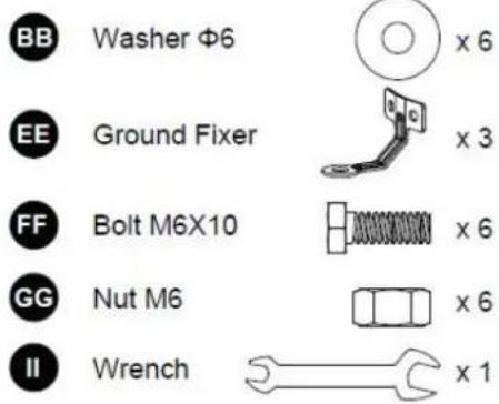
Bolt M6 x 10
Qty. 6


Nut M6 Qty. 6

Philips screwdriver Qty.1

Wrench Qty.1
PROCESO DE MONTAJE
Do not use the patio heater for indoors, as it may cause personal injury or property damage
This outdoor heater is not intended to be installed on recreational vehicles and/or boats.
- Installation and repair should be done by a qualified service person.
*Improper installation, adjustment, alteration can cause personal injury or property damage.
Do not attempt to alter the unit in any manner.
*Never replace or substitute the regulator with any regulator other than the factory-suggested replacement.
Do not store or use gasoline or other flammable vapors or liquids in the heater unit.
The whole gas system, hose, regulator, pilot or burner should be inspected for leaks or damage before use, and at least annually by a qualified service person.
*All leak tests should be done with a soap solution. Never use an open flame to check for leaks.
Do not use the heater until all connections have been leak tested.
*Turn off the gas valve immediately if smell of gas is detected. Turn Cylinder Valve OFF.If leak is at Hose/
Regulator connection: tighten connection and perform another leak test. If bubbles continue appearing should be
returned to hose's place of purchase. If leak is at Regulator/Cylinder Valve connection: disconnect, reconnect, and perform another leak check. If you continue to see bubbles after several attempts, cylinder
valve is defective and should be returned to cylinder's place of purchase.
*urn off the gas valve immediately if smell of gas is detected. Turn Cylinder Valve OFF.If leak is at Hose/Do not transport heater while it's operating.
Do not move the heater after it has been turned off until the temperature has cooled down.
*Keep the ventilation opening of the cylinder enclosure free and clear of debris.
*Do not paint the radiant screen, control panel or top canopy reflector.
Control compartment, burner and circulation air passageways of the heater must be kept clean. Frequent cleaning may be required as necessary.
*The LP tank should be turned off when the heater is not in use.
*Check the heater immediately if any of the following occurs:
-
The heater does not reach temperature.
-
The burner makes popping noise during use (a slight noise is normal when the burner is extinguished).
-
Smell of gas in conjunction with extreme yellow tipping of the burner flames.
The LP regulator/hose assembly must be located out of pathways where people may trip over it or in area where the hose will not be subject to accidental damage.
Any guard or other protective device removed for servicing the heater must be replaced before operating the heater.
Adults and children should stay away from high temperature surface to avoid burns or clothing ignition.
Children should be carefully supervised when they are in the area of the heater.
*Clothing or other flammable materials should not be hung on the heater or placed on or near the heater.
To change the gas cylinder in a amply ventilated area, away from any ignition source (candle, cigarettes, other flame producing appliances, ...);
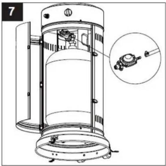
To check that the regulator seal is correctly fitted and able to fulfill its function showed as photo right;
To not obstruct the ventilation holes of the cylinder housing;
To close the gas supply at the valve of the gas cylinder on the regulator after use;
In the event of gas leakage, the appliance shall not be used or if alight, the gas supply
shall be shut off and the appliance shall be investigated and rectified before it is used again;
*To check the hose at least once per month, each time the cylinder is changed, or each time before long time no use. If it shows signs of cracking, splitting or other deterioration it shall be exchanged for new hose of the same length and of the
equivalent quality;
*The use of this appliance in enclosed areas can be dangerous and is PROHIBITED;
*Read the instructions before using this appliance. The appliance must be installed in accordance with the
instructions and local regulations.
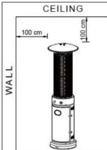
HEATER STAND AND LOCATION
The heater is primarily for outdoor use only. Always ensure that adequate fresh air ventilation is provided.
Always maintain proper clearance to non protected combustible materials i.e. top 100 cm and sides 100 cm minimum.
Heater must be placed on level firm ground.
Never operate heater in an explosive atmosphere like in areas where gasoline or other flammable liquids or vapors are stored.
To protect heater from strong wind, anchor the base securely to the ground with screws.
GAS REQUIREMENTS
Use propane, butane or their mixtures gas only. We strongly recommend to use propane, because it has a lower freezing point, suitable to be outdoor. The pressure regulator and hose assembly to be used must
conform to local standard codes. The installation must conform to local codes, or in the absence of local codes, with the standard for the storage and handling of liquid petroleum gases. A dented, rusted or damaged tank may be hazardous and should be checked by your tank supplier. Never use a tank with a damaged valve connection.
LEAKAGE TEST
Gas connections on the heater are leak tested at the factory prior to shipment. A complete gas tightness check must be performed at the installation site due to possible mishandling in shipment or excessive pressure being applied to the heater. Make a soap solution of one part liquid detergent and one part water. The soap solution can be applied with a spray bottle, brush or rag. Soap bubbles will appear in case of a leak. The heater must be checked with a full cylinder. Make sure the safety control valve is in the OFF position. Turn the gas supply ON. In case of a leak, turn off the gas supply. Tighten any leaking fittings, then turn the gas supply on and recheck. Never leak test while smoking.
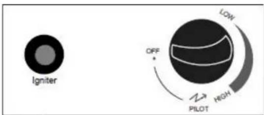
- Turn on the valve on the gas supply cylinder completely.
- Press and turn the variable control knob to PII OT position (counter-clockwise 90^
- Press down the variable control knob and hold for 60 seconds. While holding down the variable control knob, press the igniter button several times until pilot flame lights. Release the variable control knob after the pilot flame lights. Note: If a new tank has just been connected, please allow at least one minute for the air in the gas pipeline to purge out through the pilot hole. Variable control knob can be released after the pilot flame lights. If the pilot flame does not light or it goes out, repeat step 3.
- After the pilot flame lights, turn the variable control knob to maximum position and leave it there for 5 minutes or more before turning the knob to desired temperature position.
Warning: check that no broken on the glass is found before operation
TO TURN OFF THE HEATER
- Turn the variable control knob to PILOT position.
- Press and turn the variable control knob to OFF position
Off: Turn off.
Max: Maximum temperature
Min: Minimum temperature
- TURN OFF THE VALVE ON THE GAS SUPPLY CYLINDER COMPLETELY.
CLEANING AND CARE
Wipe off powder coated surfaces with soft, moist rag. Do not clean heater with cleaners that are combustible or corrosive.
Remove debris from the burner to keep it clean and safe for use.
Cover the burner unit with the optional protective cover when the heater is not in use.
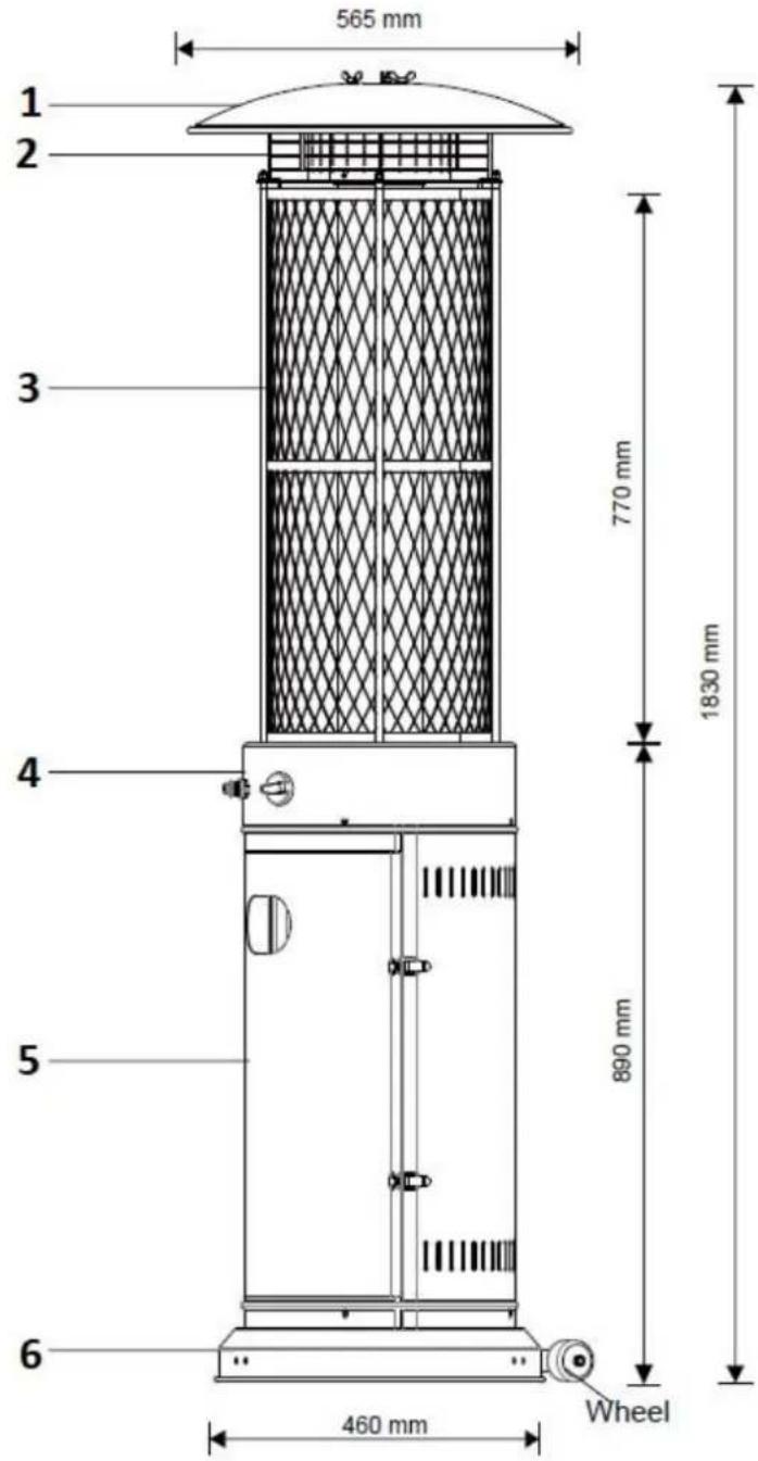
- Reflector
- Upper protective grille
- Protective grille
- Control knob
- Cylinder housing
- Base
PARTS AND SPECIFICATIONS
Specifications
- Use propane or butane.
Max. wattage: 11000 watts
Min. wattage: 5000 watts
Consumption:800gr/h
Using the proper regulator according to outlet pressure of regulator as showed in the table above.
| APPLIANCE CATALOGY: | 13+(28-30/37) | |
| TYPE OF GAS: | Butane | Propane |
| GAS PRESSURE: | 28-30mbar | 37 mbar |
| OUTLER PRESSURE OF REGULATOR: | 30mbar | 37 mbar |
Table of injector
| APPLIANCE CATEGORY: | I3+(28-30/37) | |
| TYPES OF GAS: | Butane | Propane |
| GAS PRESSURE: | 28-30mbar | 37 mbar |
| TOTAL HEAT INPUT (Hs): (Qn) | 11 Kw (800g/h) | |
| INJECTOR SIZE: | 1.75 mm for main burner 0.22 mm for pilot burner | |
- The hose and regulator assembly must conform to local standard codes
Regulator outlet pressure should meet the corresponding appliance category showed in the specifications
The appliance requires approved hose in 0.5m
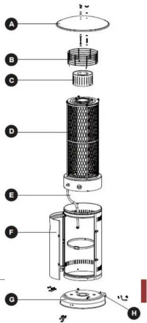
ASSEMBLY PARTS
Tools needed:
Philips screwdriver w/ medium blade Spray bottle of soap solution for leakage test
A. Reflector
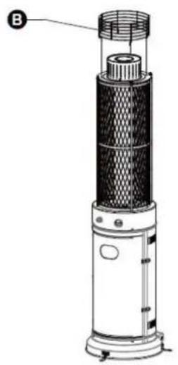
B. Upper protective grille
C. Protective mesh
D. Protective grille for tube
E. Gas hose
F. Cylinder housing
G. Base
H. Wheels
ASSEMBLY PARTS

Wing nut Qty.3

Washer 6 Qty.15

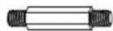
Stud Qty.3

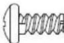
Screw M5 X 10
Qty. 11

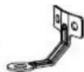
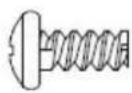
Ground Fixer Qty.3

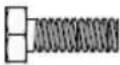
Bolt M6 x 10 Qty. 6


Nut M6 Qty. 6

Philips screwdriver Qty.1

Wrench Qty.1
ASSEMBLY PROCEDURES
- protect heater from strong wind, anchor the base to ground with screws. Turn around the base, place the ground fixer EE in the base with screws M6X10 and washers BB as show pic. 1. Ensure the base with nuts M6. After turn around base again.
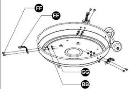
1
2
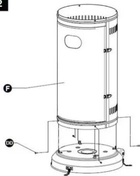
- Assemble cylinder housing on base. Use 4 screws M5X10 to screw it on base.

Screw M5X10

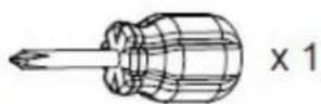
Philips screwdriver
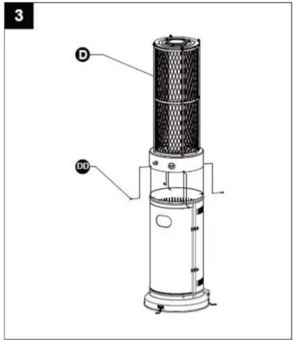
- Assemble heating unit. Place unit D on cylinder housing and screw it with 4 screws M5X10 to assemble the heater on cylinder housing.

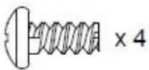
Screw M5X10
X4

Philips screwdriver
X1
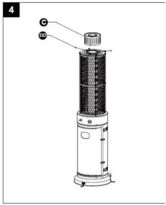
- Assemblage of mesh C. Assure it to heating unit with 3 screws M5X10.

Screw M5X10
X3

Philips screwdriver
X1
5
- Place upper protective grille B on heating unit directly.
CAUTION: Do not hang clothes or other flammable material on heater or close to it. IT IS VERY HOT! DON'T TOUCH IT!
6
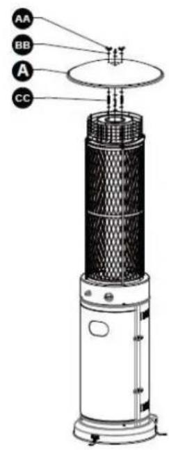
- Assemble the reflector onto the flame screen.
Screw the 3pcs stud on the flame screen, put 3pcs washer 6 onto the top of stud, then put the reflector onto the stud, secure them with 3pcs washer 6 and 3pcs wing nut.

Wing nut
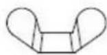
X3

Washer 6
X9

Stud
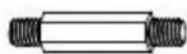
X3
- Connect gas hose to gas regulator and adjust it with clamps. After that, connect gas regulator to gas bottle. ATTENTION! Ensure that gas hose doesn't keep contact with hot surface, because it could melt and cause a fire. After place gas bottle in its place, place belt to it avoiding it falls down.
- Leak check. You must check it before first use, each year and when you replace any gas component as hose or regulator. Don't smoke while you are checking gas leak and remove all ignition fonts nearby. Put knob in OFF position. Open the gas valve of regulator. With a solution half-by-half of water and soap, brush every joins, regulator connections, hose, knobs and valves. If bubbles appear it
will mean there is a gas leak. Tighten well every connection o change the part in the case it is damaged. In the case that you cannot stop gas leak, close gas valve immediately and advice technical service. Do not use the heater until you don't solve gas leak.
PROBLEMS CHECK LIST
| PROBLEM | PROBABLE CAUSE | SOLUTION |
| Pilot will not light | Gas valve may be OFF | Turn the gas valve ON |
| Tank fuel empty | Refill LPG tank | |
| Opening blocked | Clean or replace opening | |
| Air in supply system | Purge air from lines | |
| Loose connections | Check all fittings | |
| Pilot will not stay on | Debris around pilot | Clean dirty area |
| Loose connections | Tighten connections | |
| Thermocouple bad | Replace thermocouple | |
| Gas leak in line | Check connections | |
| Lack of fuel pressure | Tank near empty. Refill LPG tank | |
| Burner will not light | Pressure is low | Tank near empty. Refill LPG tank |
| Opening blocked | Remove and clean | |
| Control not ON | Turn valve to ON | |
| Thermocouple bad | Replace thermocouple | |
| Pilot light assembly bent | Place pilot properly | |
| Not in correct location | Position properly and retry |
FRANÇAIS
LIRE LES INSTRUCTIONS AVANT LA MISE EN FONCTIONNEMENT
Screw M5 X 10
Qty. 11


Bolt M6 x 10 Qty. 6


Nut M6 Qty. 6

Philips screwdriver Qty.1


Wrench Qty.1
Screw M5 X 10
Qty. 11

Ground Fixer Qty.3

Bolt M6 x 10 Qty. 6


Nut M6 Qty. 6

Philips screwdriver Qty.1

Wrench Qty.1


Brand : Orbegozo
Model : PHE 90
Category : Cooker