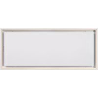
Pureline Pro Compact 6921 - Range hood NOVY - Free user manual and instructions
Find the device manual for free Pureline Pro Compact 6921 NOVY in PDF.


| Product type | Recessed ceiling hood |
| Brand | Novy |
| Model | Pureline Pro Compact 6921 |
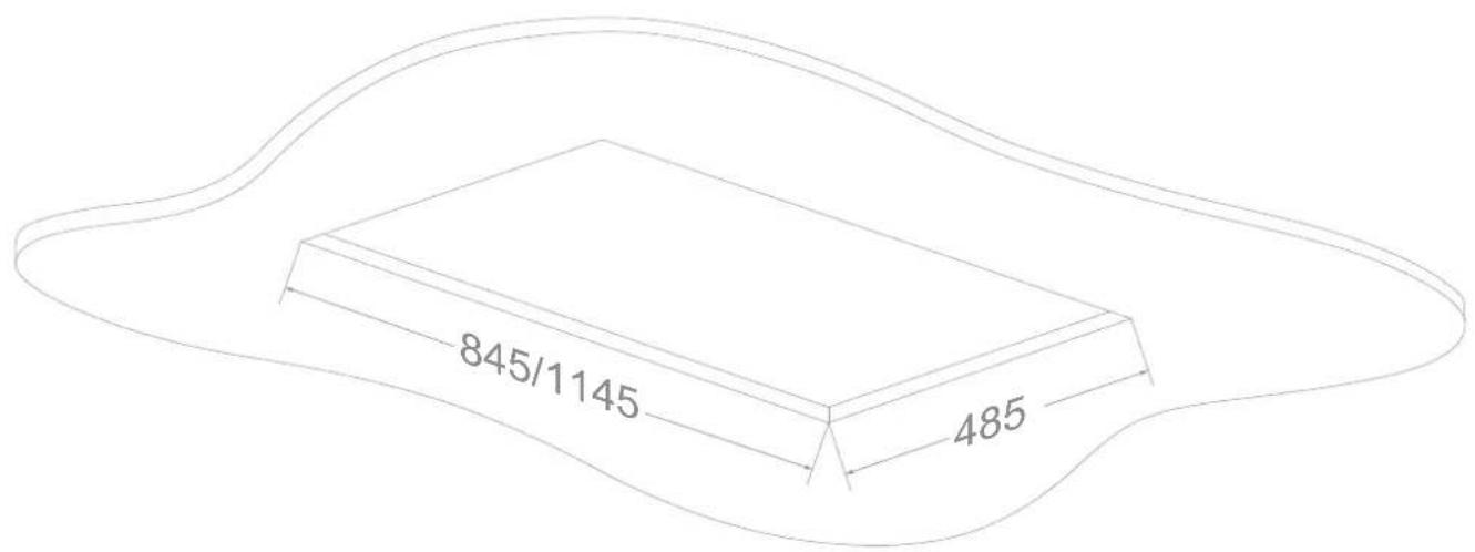
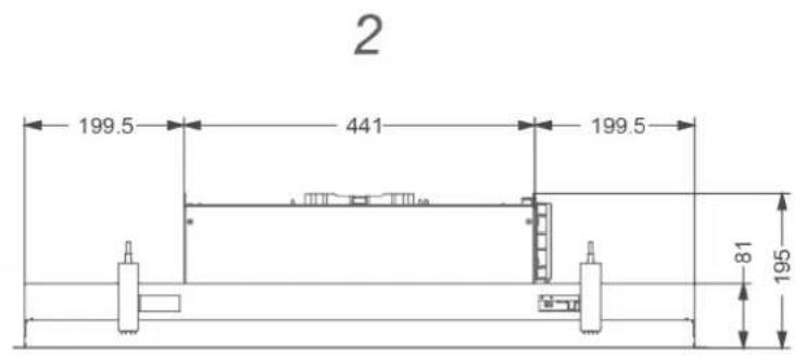
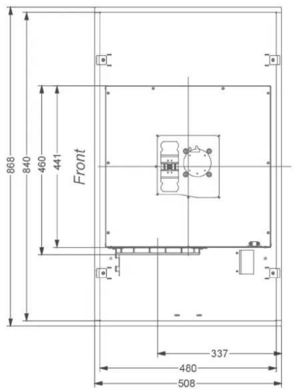
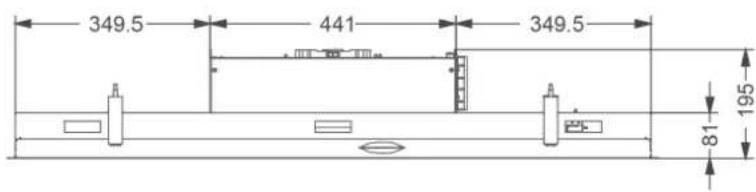
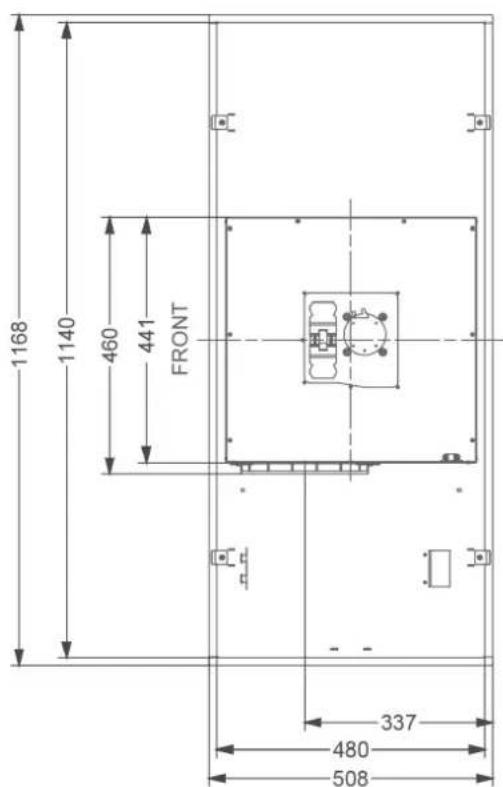
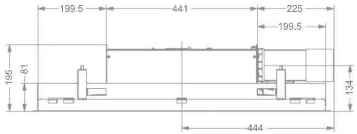
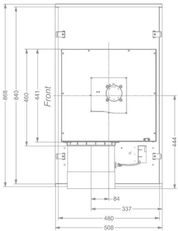
| Cutout dimensions (L x W) | 1145 x 485 mm |
| Electrical connection | 230 V ~ 50 Hz, grounded plug |
| Recommended mounting height | 600 to 1600 mm (electric/ceramic cooking) 650 to 1600 mm (gas/induction cooking) |
| Material | Stainless steel |
| Filters | Removable metal grease filters |
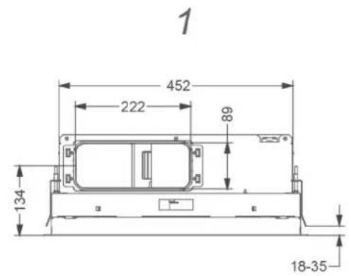
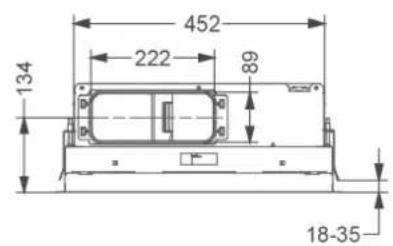
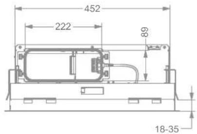
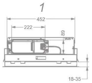
| Exhaust | Flat duct 89x222 mm or round Ø150 mm (adaptation possible) |
| Functions | Manual speed control, compatible with Novy Sense sensor (optional), InTouch connection (optional) |
| Noise level | Not specified (refer to technical documentation) |
| Weight | Approximately 25 kg (estimate) |
| Maintenance | Regular filter cleaning, do not use steam or high-pressure cleaner |
| Safety | Residual-current circuit breaker recommended, emergency stop by disconnection |
| Accessories | Novy Sense sensor kit (6910.070), recirculation kit, window switch, flexible ducts |
| Repairability | Spare parts available from Novy, repair by certified technician |
Frequently Asked Questions - Pureline Pro Compact 6921 NOVY
User questions about Pureline Pro Compact 6921 NOVY
0 question about this device. Answer the ones you know or ask your own.
Ask a new question about this device
Download the instructions for your Range hood in PDF format for free! Find your manual Pureline Pro Compact 6921 - NOVY and take your electronic device back in hand. On this page are published all the documents necessary for the use of your device. Pureline Pro Compact 6921 by NOVY.
USER MANUAL Pureline Pro Compact 6921 NOVY
1 SAFETY AND ASSEMBLY REGULATIONS
Further information on Novy products, accessories and services may be found on the internet: www.novy.com
These are the installation instructions for the appliance as shown on the front. The directions for use are in a separate booklet supplied with the appliance.
These installation instructions make use of a number of symbols. The meanings of the symbols are shown below.
| Symbol Meaning Action | ||
| Indication Explanation | Indication of an indication on the hood. | |
| Warning This symbol indicates an important tip or a dangerous situation | ||
Observe this instruction in order to prevent injury and damage to property.

ings before installation
- This appliance complies with the applicable safety instructions. However, inexpert installation may cause personal injury or damage to the appliance.
The appliance is intended exclusively for household use (preparation of food) and excludes all other domestic, commercial or industrial use. Do not use the appliance outside.
-
Check the condition of the appliance and the installation fittings as soon as you remove them from the packaging. Remove the appliance from the packaging with care. Do not use sharp knives to open the packaging.
-
Do not install the appliance if it is damaged, and in that case inform Novy.
-
Check on the basis of the drawing A that all the materials for installation have been supplied. The grease filters are in the appliance.
-
Novy is not liable for damage resulting from incorrect assembly, incorrect connection, incorrect use or incorrect operation.
-
The installation and electrical connection of the appliance should be left to a recognised expert.
-
Safety is guaranteed only with expert installation in accordance with the installation manual. The installing technician is responsible for proper operation at the installation location.
-
For easier installation of the appliance, it is advisable to carry it out with at least 2 people.
-
Read the directions for use and the installation instructions before installing and using this appliance. You will find important information here for the assembly and use of the appliance.
Metal parts may have sharp edges, and you may injure yourself on them. For that reason, wear protective gloves during installation.

ation instructions for the appliance
-
Ensure that the structure on or in which the appliance is to be installed can bear its weight.
-
Faulty or damaged parts may only be replaced by original Novy parts.
The larger the distance between the appliance and the hob, the less easily the cooking vapours can be taken up by the appliance. For this reason, pay heed to the stated (recommended) installation height.
If a different distance is specified in the installation instructions for the gas hob, the largest distance indicated applies.
-
In order to ensure that the cooking vapours are taken up in an optimal way, the appliance, or the structure into which the appliance is being installed, should extend over the hob. When using your own structure, ensure that the appliance is installed centred above the hob.
-
For optimal operation, the hob should not be larger than the appliance or the structure into which the appliance is installed.

st or recirculation
Before starting to install, you need to have decided whether you are making an extraction duct to the outside, or whether you are going to use the extractor hood as a recirculation extractor hood. If opting for recirculation, you will find the recirculation kit with the accessories in these installation instructions.

the exhaust duct
For optimum performance of the cooker hood it is important to pay attention to the following points:
-
The hood has a connection for flat exhaust duct (89× 222mm) . If necessary, this can be transferred to a circular exhaust duct of 150mm at a later stage.
-
You will achieve the best operation and lowest possible noise level for the appliance by connecting the extraction duct by as short a route as possible, with as few bends as possible and using the prescribed diameter.
-
Use smooth, non-flammable pipes with an internal diameter that is equal to the external diameter of the connection nozzle of the hood.
Use flat duct with rounded corners and with air deflectors. Available at Novy.
-
Do not reduce the exhaust diameter. This will lower the capacity and raise the noise level.
-
Avoid right-angle bends. Use rounded bends for effective airflow.
-
Use of a flexible extraction hose should be kept to a minimum, and it should only be used for making small bridging sections, for example as the link between the outlet nozzle and the extraction duct. Maximally extend flexible ducts and cut them to size.
-
Ensure that the extraction duct is not crushed and that there are no kinks in the duct.
-
Use a hose clamp or aluminum tape for airtight connections.
-
With a horizontal extraction duct, install it at a slight incline to ensure that condensation does not run back to the appliance.
-
Condensation may arise as a result of temperature differences if the extraction duct passes through cool rooms. Ensure that the extraction duct is insulated.
-
In case of an exhaust pipe through the outside wall passing a cavity wall, make sure that the exhaust duct fully bridges the cavity and slightly declines to the outside.
-
In case of an exhaust pipe through the wall, use a wall vent.
In case of an exhaust pipe through the roof, use a double-walled roof passage with adequate outlet capacity.
- When connecting to a short extraction duct, it may be desirable to install a non-return valve in the duct in order to prevent backdraught from wind.

-
Make sure that sufficient air is supplied. Fresh air can be supplied by slightly opening a window or an outside door or by installing an inlet grate.
-
The appliance may not be connected to a flue or chimney that is currently in use, or that serves as ventilation for rooms with hearths.
However large the kitchen or the room with open kitchen is, only so much air can be extracted from the room as is supplied. Too little air supply could result in a yield loss of 50% and more.
If the extraction is used at the same time as a combustion system (for example heaters fired by gas, oil, wood or coal, hot water boilers using gas, gas hobs and gas ovens), combustion gases may be sucked back in and lead to poisoning.
A combustion system uses air from the room as combustion air. Combustion gases arise as a result, which are removed to the outside by an extraction system.
The appliance sucks in air from the kitchen and adjacent rooms. Negative pressure occurs if the air supply is inadequate. The toxic gases are then sucked back from the chimney or extraction duct into the room.
With simultaneous use of the appliance and combustion appliances in the same room, the negative pressure may not exceed 4Pa (= 0.04mBar) .Negative pressure can be prevented by allowing sufficient air into the room through openings that cannot be closed (for example through windows or doors, in combination with a ventilation cabinet in the wall).
Have an expert assess the overall ventilation system in your home for a proposal on suitable measures in the area of air supply.
When using the appliance with an internal or external motor (unit) with air extraction to the outside, there must be adequate air supply in the room where the appliance has been installed / is positioned, so that fresh air can flow in. Fresh air can be provided by tilting a window, opening a door or installing an inlet grille.
With an appliance with recirculation, there must be a minimum of ventilation in the room where the appliance has been installed / is positioned. Ventilation can be provided by the overall ventilation in the home or by tilting a window or opening a door.
Certain appliances are fitted with a connection for a window contact switch (see the technical specifications for your appliance). If the appliance is to operate at the same time as a heating appliance that needs air from the room, and if the required supply can only take place through a single open window, there is the option of connecting the appliance to a window contact switch (not included). This ensures that the appliance operates only when the window is open. If the window is closed, the fan cannot be switched on.
Contact your technician for the correct accessories for your appliance.
Installation instructions for the outlet
- The appliance may only be connected with the power plug to a socket with an earth (230 V - 50 Hz).
- Safety is only assured when the appliance is connected to an earth cable in accordance with the instructions laid down.
- The appliance must be able to be disconnected from the power at any desired point.
- Position the socket in such a way that the power plug of the appliance can be inserted easily.
- Do not use an extension cable for the connection to the electrical mains.
- Electric shock: never switch on a faulty appliance, this could cause an electric shock. Take the power plug out of the socket, or switch off at the distribution cabinet. Contact the Novy service department.
- Repairs and replacing faulty or damaged wiring must only be carried out by technicians who have undergone instruction by Novy.
- Moisture that has got into the appliance may cause an electric shock. Do not use a high pressure or steam cleaner.
2 ACCESSORIES
Novy Sense sensor
This cooker hood can be equipped with an automatic speed control (Novy Sense sensor). In auto mode, a sensor inside the appliance recognises the intensity of cooking fumes and odours. The optimum motor speed is set automatically using this sensor.
This optional kit must be fitted to the motor outlet before installing the cooker hood.
- Kit Novy Sense sensor for automatic
speed control upon detection of
cooking fumes and odours 6910.070
Flexible duct
In order to simplify the installation, it is advisable to make the final piece between the flat duct work and hood from flexible, flat exhaust duct (906.408).
Recirculation
If you choose recirculation, Novy offers the outlet box in various sizes, including type 841.400/842.400/843.400 or type 7931.400/7932.400/7933.400.
Accessories flat exhaust duct
-
Flexible exhaust tube length 750 mm 906.408
-
Flat exhaust channel duct1000 mm
(dimensions: 89x222x1000 mm) 906.401
- Connection piece (dimensions:
Transition piece to 0150 mm
(dimensions: 94× 227× 190mm 906.406
- Wall conduct kit for for flat exhaust duct
89x222mm including built-in heat retention
non-return valve 906.425
- Stainless Steel blind grill with non-return valve
dimensions: 290× 160mm 906.407
Accessories circular exhaust tube
- Circular exhaust tube
length 1000 mm Ø150 mm 906.415
-
Connection piece Ø150 mm 906.417
-
Curve 90° 0150 mm 906.416
Aluminium external grill for 0150 mm 906.178
Wall conduct kit for ducting 0150 mm including
built-in heat retention non-return valve 906.420
Non-return valve 150mm 906.432
General accessories
-Hose clamp adjustment 060-215 mm 906.291
Aluminium tape 50 m 906.292
- Stainless steel cleaner: maintenance product for cleaning the stainless steel 906.060
InTouch
InTouch offers you the possibility to control the Novy cooker hood from the Novy InTouch induction cooking plate. The ceiling hood may, as a default, be combined with InTouch induction cooking plates.
Visit the website for the different models of induction cooking plates with InTouch.
Window switch
This hood is equipped with a connection for a contact window switch. If the hood is to work simultaneously with a heating appliance that pulls air from the room, and if the required supply of fresh air can only be through an open window, it is possible to connect a window contact switch (not supplied) to the hood.
This ensures the hood only works if the window is open. When the window is closed, the fan can not be turned on. A window contact cable set is available as an accessory (part number 990.036). Using the cable set, it is possible to make a connection between the hood controller to the outside of the hood. A window contact switch can then be connected (not included).
Further information on Novy products, accessories and services may be found on the internet: www.novy.com
NL Montage ZONDER optionele Novy Sense sensor
FR Installation SANS le capteur optionnel Novy Sense
DE Installation OHNE optionalen Novy Sense Sensor
EN Installation WITHOUT the optional Novy Sense sensor
NL

afondunitkan
feiling unit can be:
built into plates with a thickness of 18-35mm. Do not mount directly into gypsum board; always make sure there is reinforcement for the tightening of the mounting clamps. Make sure there is a socket near the ceiling unit, so that the power may, at all times, be removed from the ceiling unit.

se of the
substantial own weight of the hood, the ceiling must have sufficient load bearing capacity.

commended
mounting height for an electric or ceramic cooking plate is min. 600 mm and max. 1600 mm . The mounting height for a gas or induction cooking plate is min. 650 mm and max. 1600 mm .

1×840029
1
2
NL 3 INSTALLATIE
Create an cut-out opening:
Model 6910/6911/6912 Cut-out 845mm× 485mm
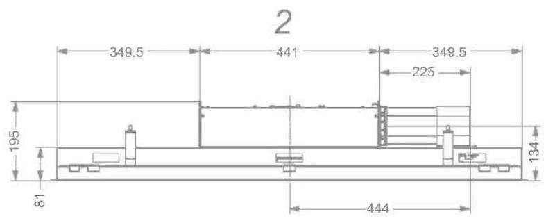
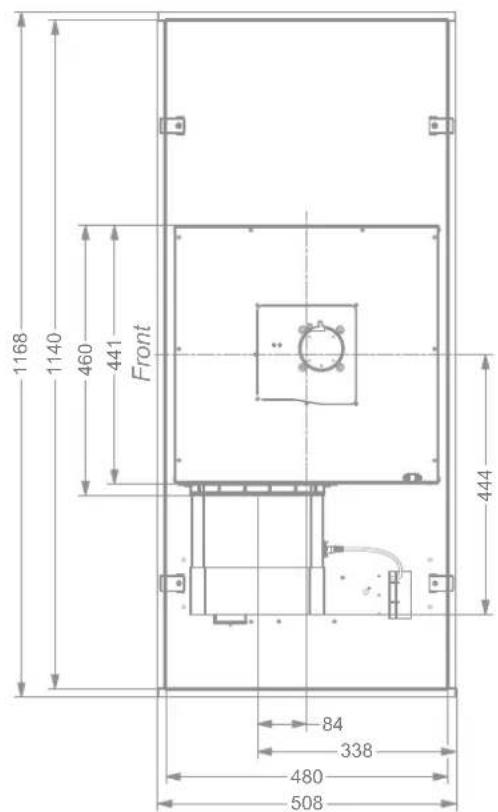
Model 6920/6921/6922 Cut-out 1145mm× 485mm
The cooker hood should be mounted with the control on the right side of the user, so that the bottom panel opens away from you and the filter can be easily removed from the cooker hood.
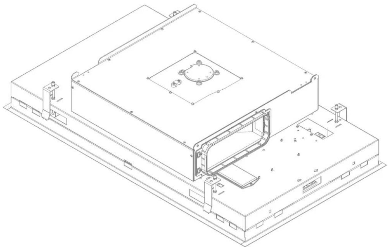
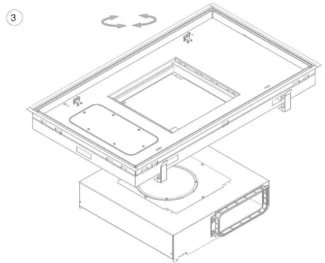
As standard, the exhaust opening of the motor is to right. If required, the exhaust opening can be be modified.
- Open the bottom panel and remove the filters from the hood.
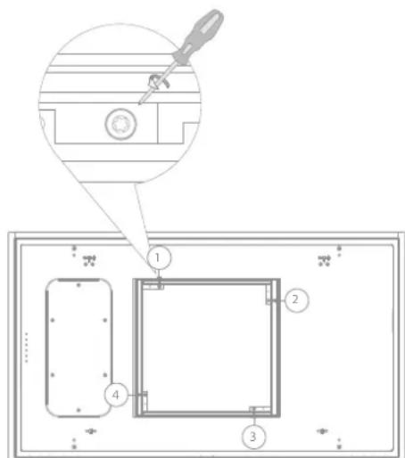
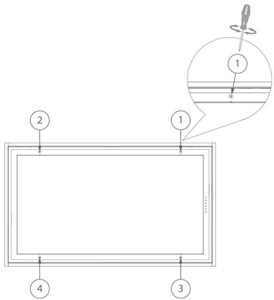
- Loosen the 4 screws in accordance with the drawing.
Turn the motor so the exhaust is in the desired position and screw the motor with the 4 screws.

NL
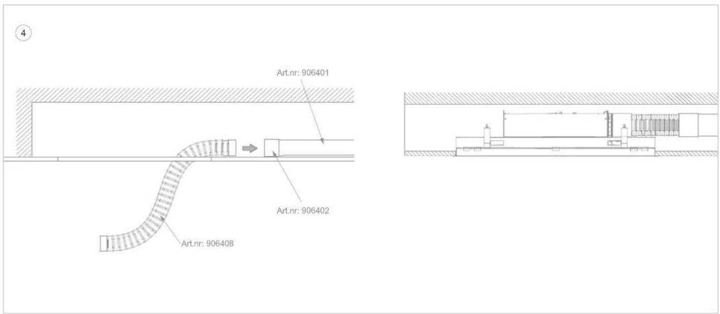
In order to simplify the installation, it is advisable to make the final piece between the flat duct work and hood from flexible, flat exhaust channel. This is available as accessory from Novy (906.408).
If the flexible flat exhaust channel is to be used, connect the flexible exhaust channel onto the connection piece with tape (taking the length of the flexible exhaust channel into account).
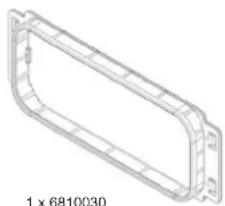
Click the connection piece (6810.030) onto the motor housing and screw in 4 screws (906.116).

ble for flat exhaust charge channel (internal) dimension of 89× 222mm
Put the plug into the socket.
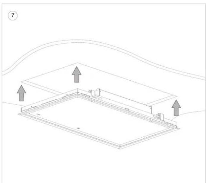
Push the ceiling unit up into the cut-out opening by pushing on the edges until you hear a firm click.

It push on the bottom panel!
The ceiling unit will now remain suspended in place.
NL
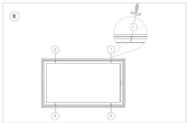
8 Tighten the 4 clamping screws by hand in order to attach the ceiling unit (caution: Do not over-tighten in gypsum boards). As soon as these clamping screws are tightened, the ceiling unit is ready for use.
9 Removing the ceiling unit
Before dismantling, protect the hob with, for example, cardboard or a cloth in case a screw or clamp falls down.
Perform the following actions only when the power is off at the wall socket.
Next, the 4 clamping screws need to be fully unscrewed. Once these are unscrewed, the ceiling unit will come down. Please note that the motor unit lies loose on the housing of the cooker hood.
Please note that the unscrewed clamping springs can fall down.
NL Montage MET optionele Novy Sense sensor
FR Installation AVEC le capteur optionnel Novy Sense
DE Installation MIT optionalem Novy Sense Sensor
EN Installation WITH the optional Novy Sense sensor
NL

Sv S
Sense sensor
sor kit is an optional accessory.

ceiling unit can be
built into plates with a thickness of 18 - 35mm . Do not mount directly into gypsum board; always make sure there is reinforcement for the tightening of the mounting clamps. Make sure there is a socket near the ceiling unit, so that the power may, at all times, be removed from the ceiling unit.

use of the
substantial own weight of the hood, the ceiling must have sufficient load bearing capacity.

commended
mounting height for an electric or ceramic cooking plate is min. 600 mm and max. 1600 mm . The mounting height for a gas or induction cooking plate is min. 650 mm and max. 1600 mm .
A
1 × 6810.030
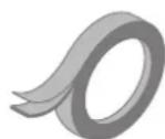
1×906292
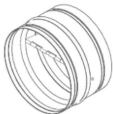
1x906432
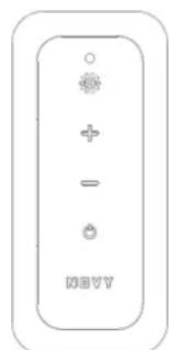
1×840049
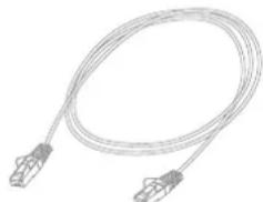
1x99004008

1× 906116
NL 3 INSTALLATIE
ALGEMEEN
This cooker hood is equipped with the optional automatic speed control (Novy Sense sensor). Disregarding the following installation instructions can have a negative effect on the automatic speed control.
Always install a non-return valve in the exhaust pipe to prevent backdraught from wind. The non-return valve is included in the Novy Sense sensor kit. Install the non-return valve as close as possible to the outer wall or roof outlet.
- Don't use the non-return valve provided in the Novy Sense sensor kit if the wall or roof outlet is already fitted with a non-return valve or if you are using a Novy wall conduct kit 906.407, 906.425, 906.420 or a Novy wall exhaust grill 906.078 or 906.178. These kits / wall exhaust grills are already equipped with a non-return valve(function).
- An arrow on the housing of the Novy Sense sensor indicates the required direction of the airflow. The arrow must pointed downstream.
The Novy Sense sensor kit has to be mounted directly at the exhaust opening of the cooker hood.
1
NL
Create a cut-out opening:
Model 6910 / 6911 / 6912 - Cut-out 845mm x 485mm
Model 6920/6921/6922 -Cut-out 1145mm x 485mm
The cooker hood should be mounted with the display on the right side of the user, so that the bottom panel opens always from you and the grease filters can be easily removed from the cooker hood.
As standard, the exhaust opening of the motor is to the right. If required, the exhaust opening can be modified.
Installation with exhaust opening to the right
Installation with exhaust opening to the left Installation with exhaust opening to front/ rear
See next pages
This cooker hood is suitable for flat exhaust ducts with (internal) dimension of 89 × 222 mm .
NL
Extremely careful if you use the cooker hood at the same time as a combustion system that requires air from the same room. In these installation instructions, carefully read the topic "air supply" in the chapter "Safety and assembly regulations".
For safe operation, it may be necessary to combine the cooker hood with a window contact switch. A window contact switch ensures that the cooker hood only works if the window is open. If the window is closed, the fan cannot be switched on.
For safe operation, it may be necessary to open an electrical air supply valve as soon as the cooker hood is switched on.
With the optional Novy input/output module 990.036 it is possible to combine a window contact switch or electric air supply valve (not included) with the cooker hood.
If this option is selected, the Novy input / output module 990.036 must be installed prior to the assembly operations in step 4 / 13/24.
The assembly of the module 990036 is explained from page 55 of this manual.
NL
Installation with exhaust opening to the RIGHT

on, do not perform any of the follow- operations while the unit is energised.
Make sure that the power is off or that the plug of the cooker hood is unplugged
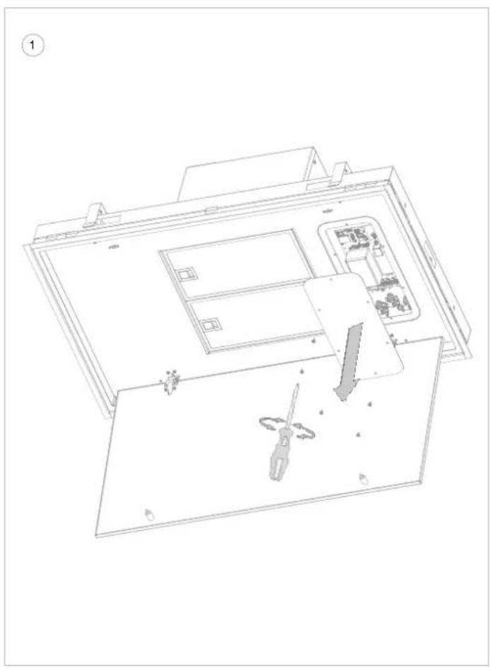
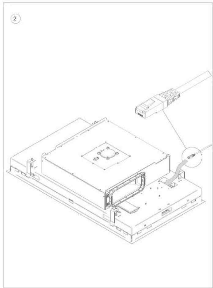
① Open the bottom panel of the cooker hood and remove the 6 screws (TX15) from the service hatch.
After this, the circuit board of the cooker hood is visible.
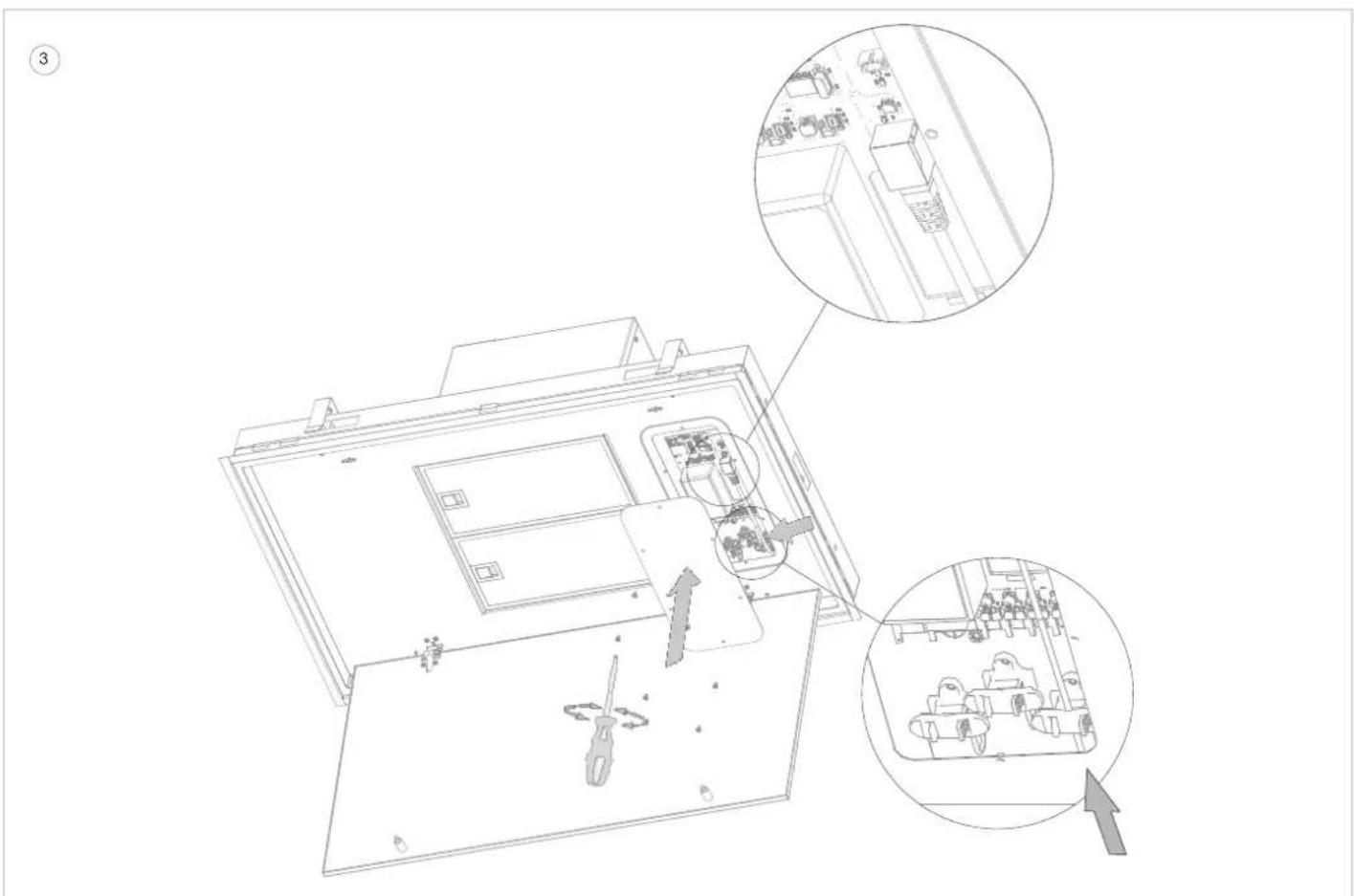
2 Route the supplied UTP cable (99004008) from above through the indicated opening so that the cable exits at the circuit board.
3 Connect the RJ45 connector of the UTP cable into the indicated connector on the circuit board.
Fix the UTP cable in the indicated strain relief.
Then replace the service hatch and fix with the 6 screws (TX15).
(4)
NL
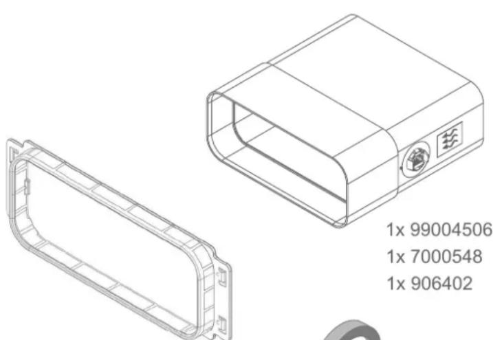
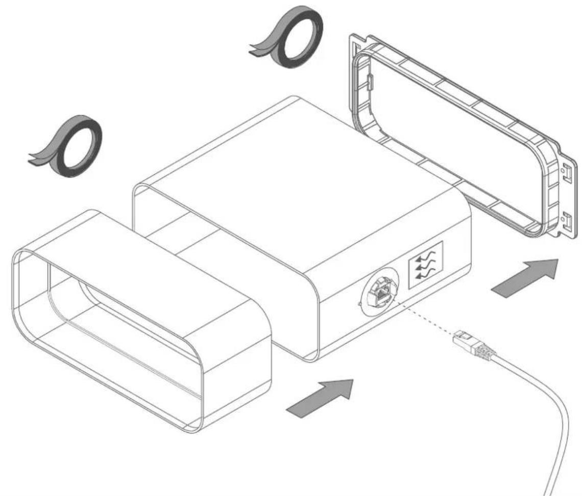
4 Click the connection piece (6810.030) onto the motor housing and screw in 4 screws for fixation (906.116).
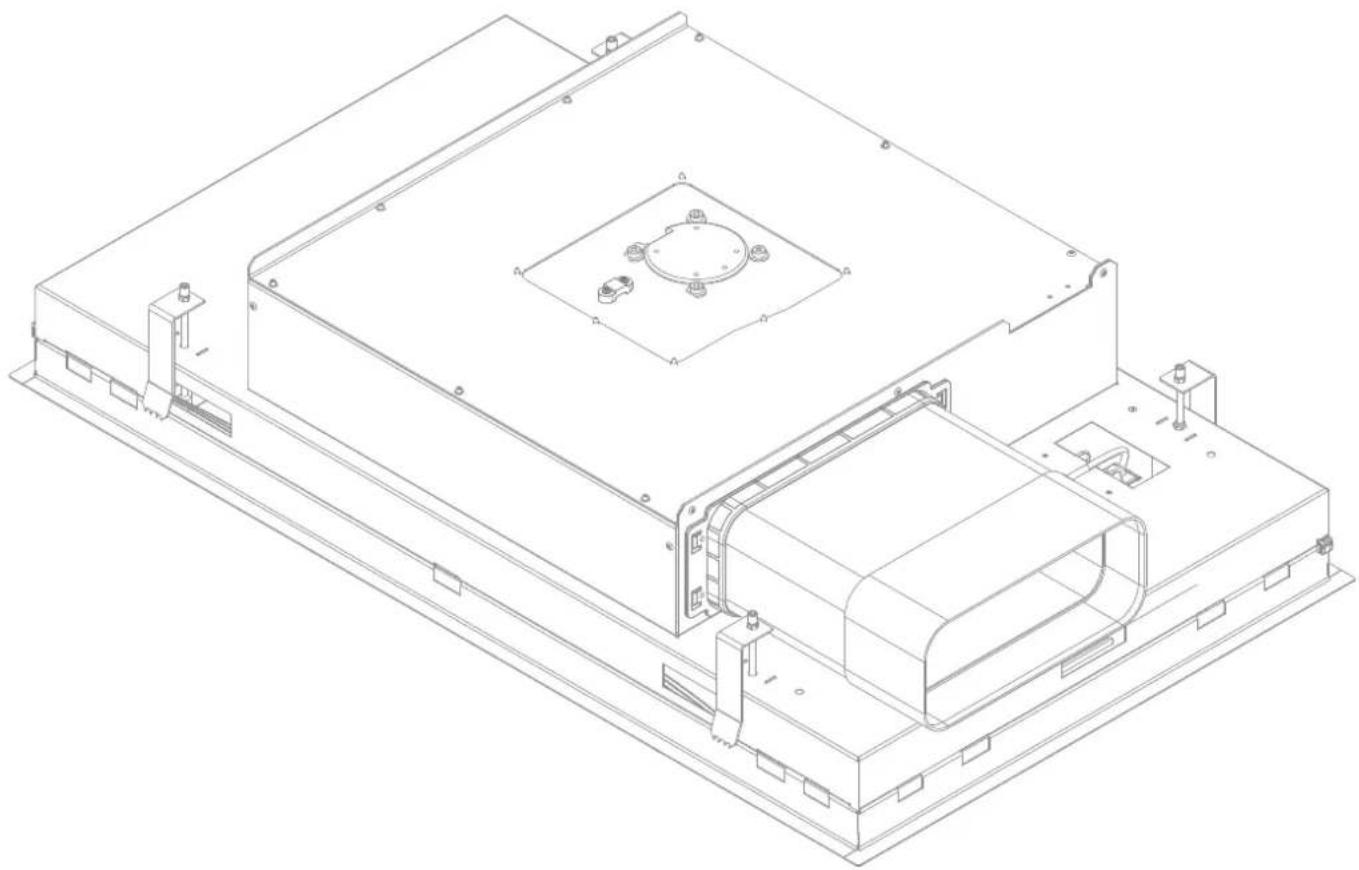
Connect the sensor kit to the connection piece (6810.030), mind the direction of the airflow as indicated on the sticker of the Novy Sense sensor. The arrow must pointed downstream. Then mount the supplied connection piece (906.402) on the sensor kit. Use tape for an airtight connection.
Connect the cable of the sensor kit to the connection socket provided in the sensor kit.
Use tape to fixate this cable to the casing of the cooker hood.
NL
To simplify the installation, we recommend using flexible flat exhaust ducting for the last section between the flat ductwork and the cooker hood. This is available as accessory from Novy (906.408).
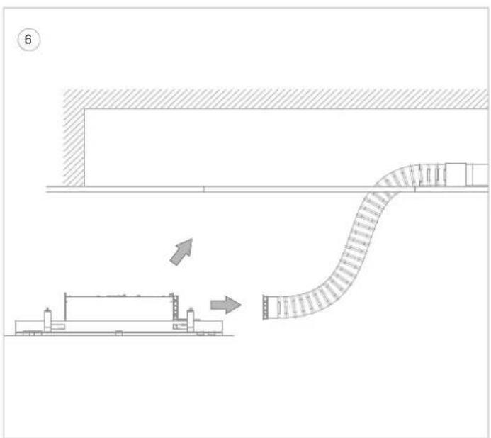
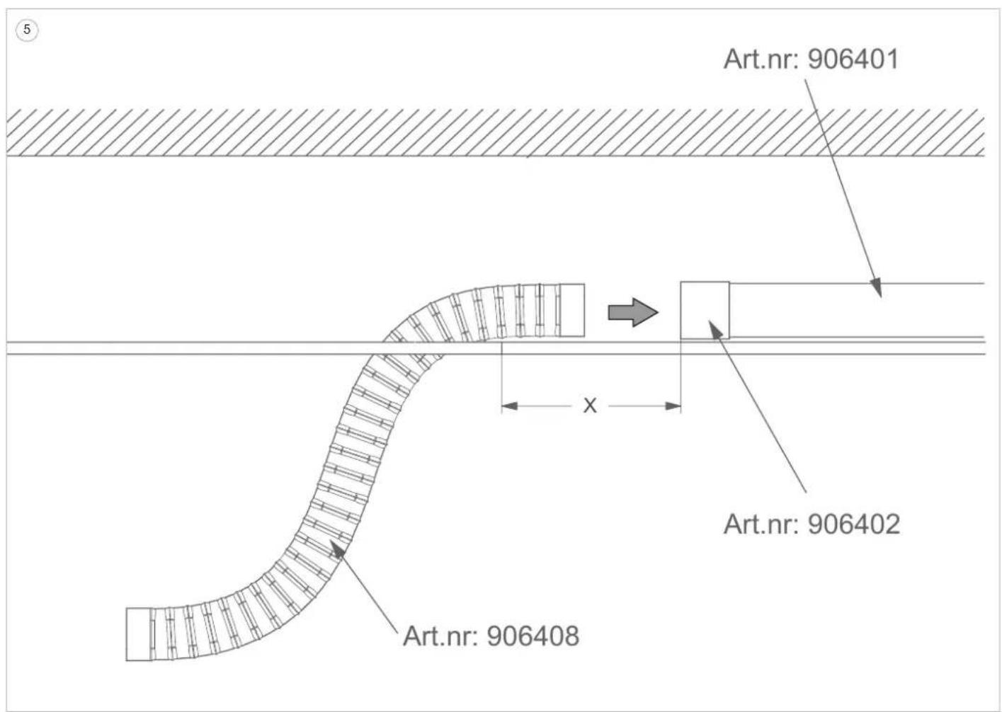
Make sure that after installation, the flexible flat duct is not bend in a S-curve (= overlap) between the cooker hood and the flat ductwork. This increases the pressure loss in the duct and has a negative effect on the efficiency of the cooker hood.
Overlap can be avoided by observing the following clearance between the end of the flat ductwork and the edge of the cut-out opening in the ceiling:
Model 6910 / 6911 / 6912 - minimum 300mm and maximum 320mm (X)
Model 6920 / 6921 / 6922 - minimum 150mm and maximum 170mm (X)
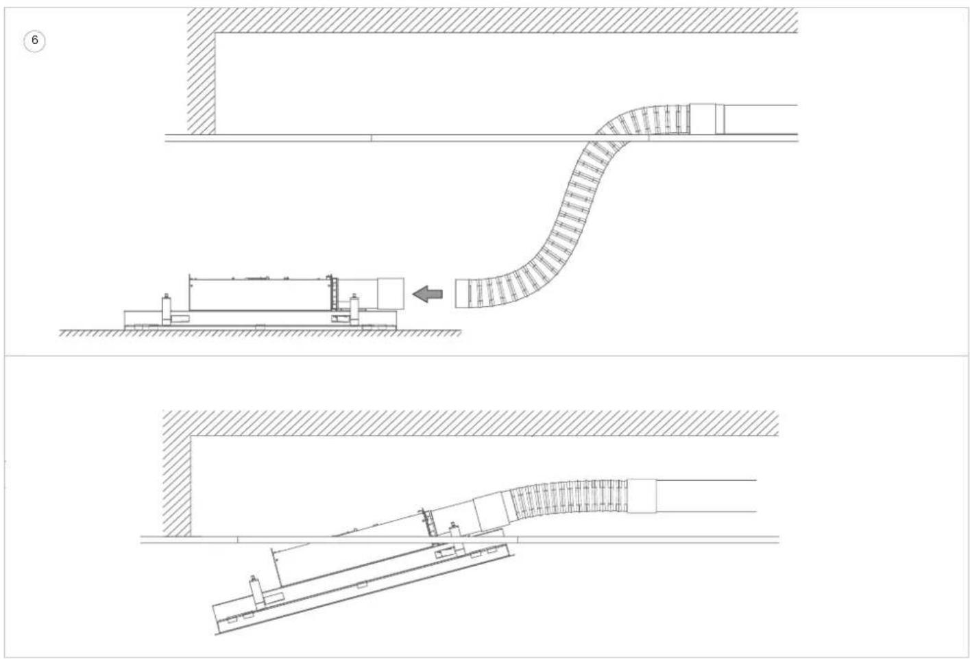
Connect the flexible flat duct (906.408) to the flat ductwork using a connection piece (906.402 not supplied). Use tape for an airtight connection. Pay attention to the required free space between the flat ductwork and the cut-out opening. Leave the flexible duct hanging out of the cut-out opening.
NL
Place the cooker hood as close as possible to the cut-out opening and connect the flexible duct to the sensor kit. Use tape for an airtight connection.
Put the plug into the socket.
Push the ceiling unit by its edges (not on the bottom panel) at an angle upwards into the cut-out opening and click it into place with the clamping springs.

It push on the bottom panel!
The ceiling unit will now remain suspended in place.
8 Tighten the 4 clamping screws by hand to permanently secure the ceiling unit (caution: do not tighten too hard in plasterboard).
The cooker hood is now ready for use.
NL
Installation with exhaust opening to the LEFT

on, do not perform any of the follooperations while the unit is energised.
Make sure that the power is off or that the plug of the cooker hood is unplugged.
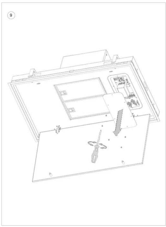
9 Open the bottom panel of the cooker hood and remove the 6 screws (TX15) from the service hatch.
After this, the circuit board of the cooker hood is visible.
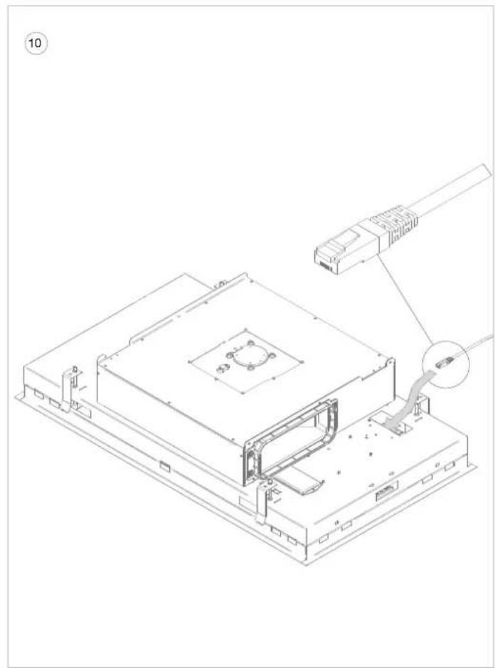
10 Route the supplied UTP cable (99004008) from above through the indicated opening so that the cable exits at the circuit board.
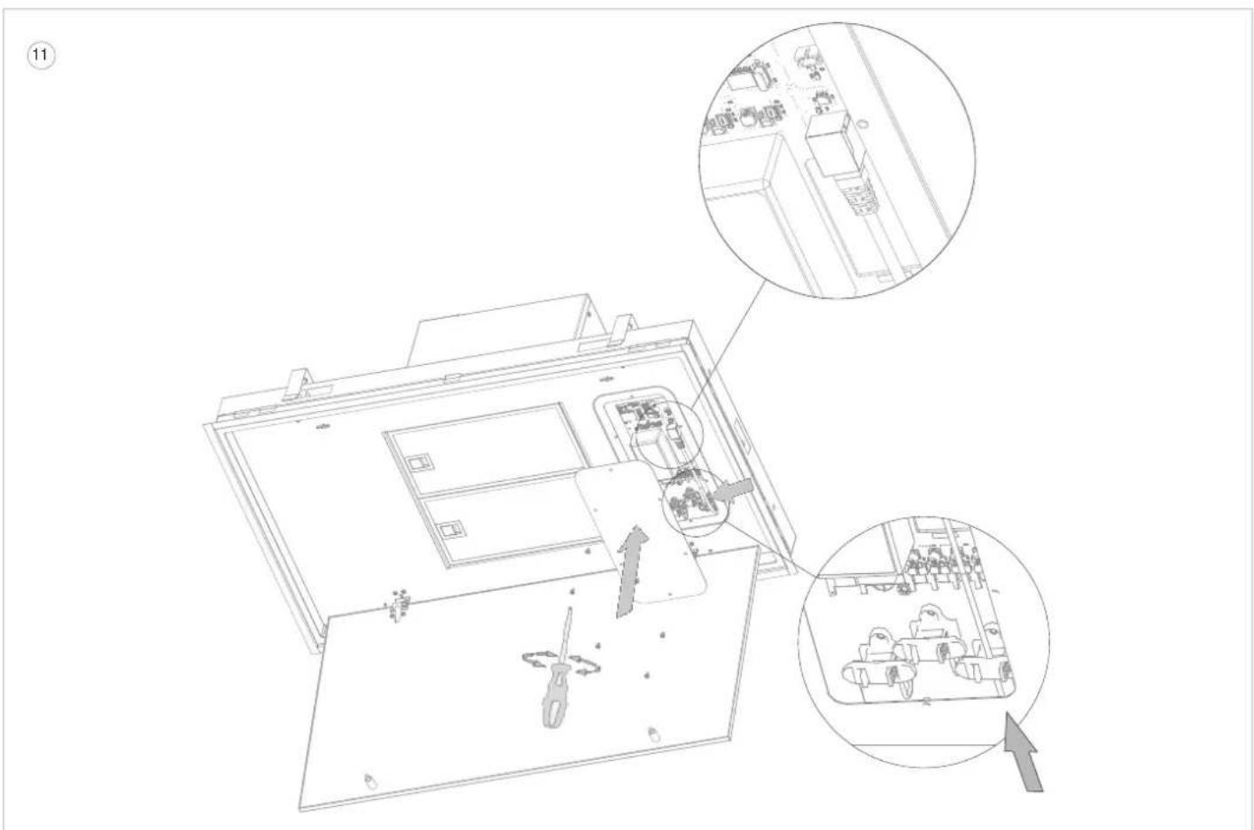
11 Connect the RJ45 connector of the UTP cable into the indicated connector on the circuit board.
Fix the UTP cable in the indicated strain relief.
Then replace the service hatch and fix with the 6 screws (TX15).
NL
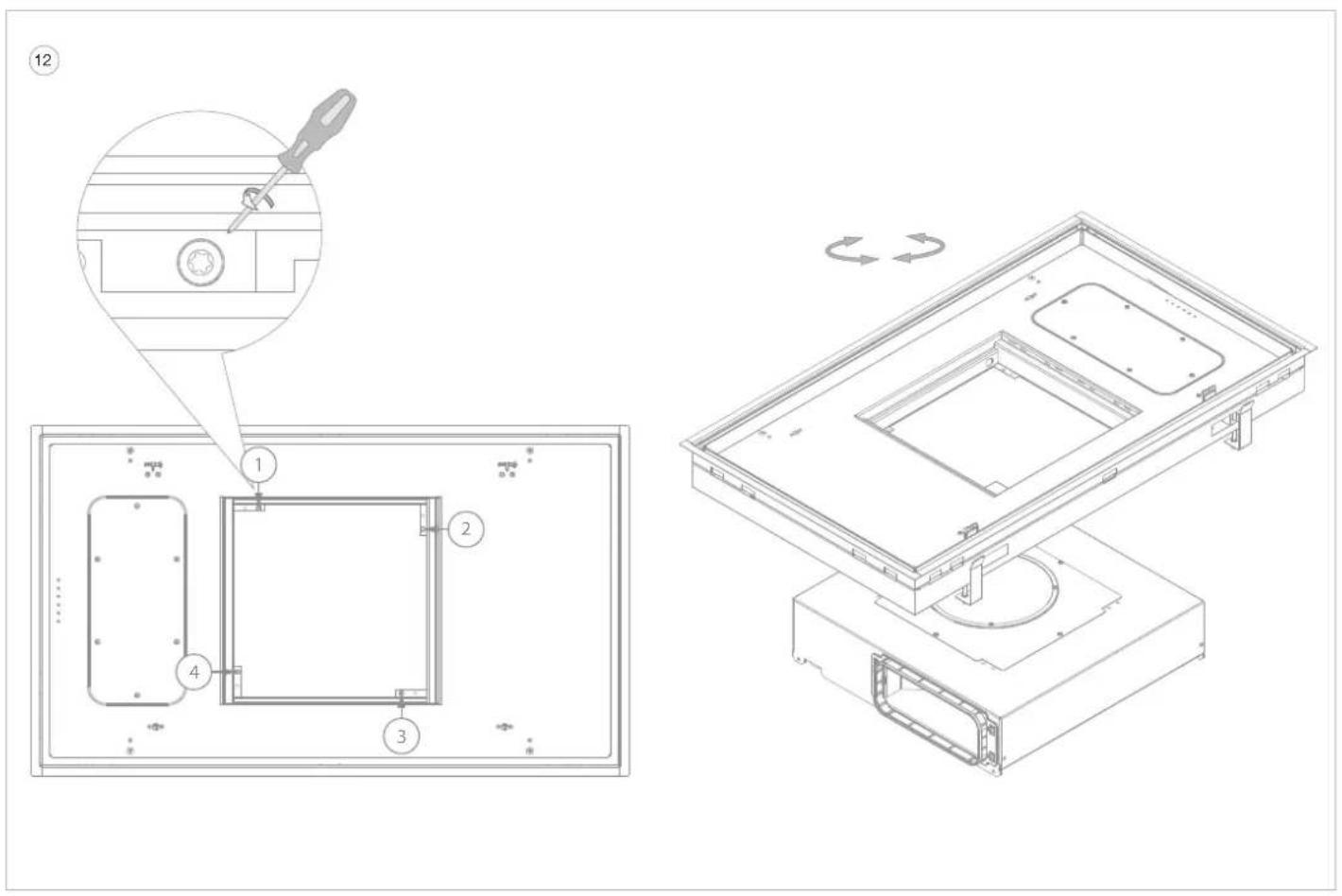
12 Open the bottom panel and remove the grease filters from the cooker hood.
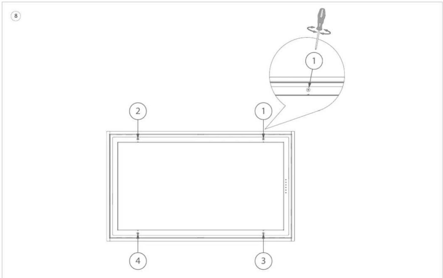
- Loosen the 4 screws in accordance with the drawing. The motor unit is now detached.
- Turn the motor unit until the exhaust opening is to the left and screw the motor unit back on using the 4 screws.
- Place the grease filters in the ceiling unit and close the bottom panel.
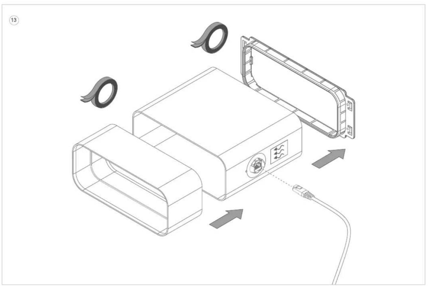
13 Click the connection piece (6810.030) onto the motor housing and screw in 4 screws for fixation (906.116). Connect the sensor kit to the connection piece (6810.030), mind the direction of the airflow as indicated on the sticker of the Novy Sense sensor. The arrow must pointed downstream. Then mount the supplied connection piece (906.402) on the sensor kit. Use tape for an airtight connection.
Connect the cable of the sensor kit to the connection socket provided in the sensor kit.
Use tape to fixate this cable to the casing of the cooker hood.
NL
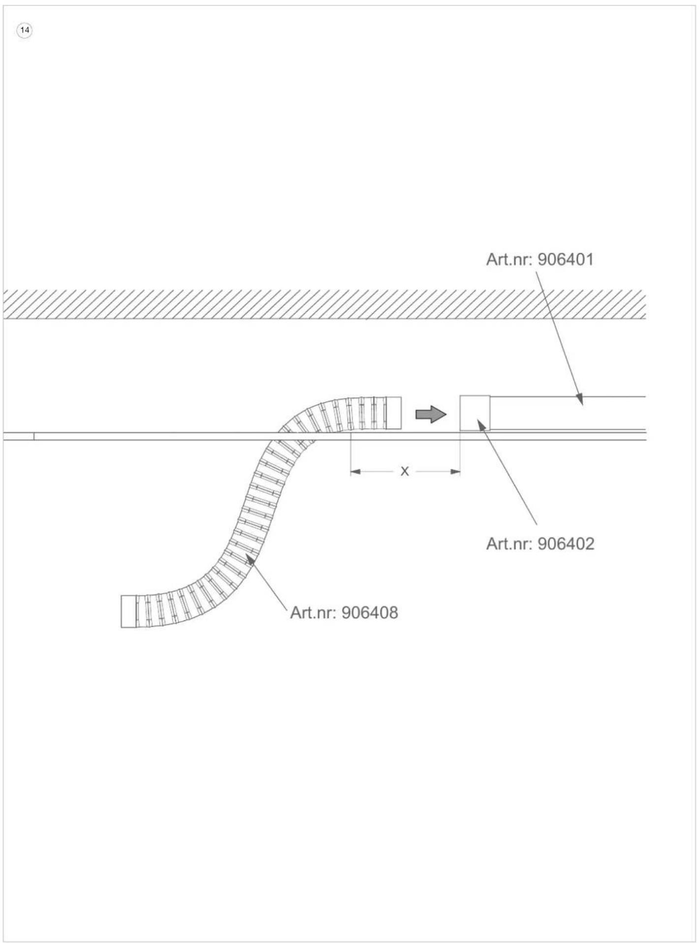
To simplify the installation, we recommend using flexible flat exhaust ducting for the last section between the flat ductwork and the cooker hood. This is available as accessory from Novy (906.408).
Make sure that after installation, the flexible flat duct is not bend in a S-curve (= overlap) between the cooker hood and the flat ductwork. This increases the pressure loss in the duct and has a negative effect on the efficiency of the cooker hood.
Overlap can be avoided by observing the following clearance between the end of the flat ductwork and the edge of the cut-out opening in the ceiling:
Model 6910 / 6911 / 6912 - minimum 300mm and maximum 320mm (X)
Model 6920 / 6921 / 6922 - minimum 150mm and maximum 170mm (X)
Connect the flexible flat duct (906.408) to the flat ductwork using a connection piece (906.402 not supplied). Use tape for an airtight connection. Pay attention to the required free space between the flat ductwork and the cut-out opening. Leave the flexible duct hanging out of the cut-out opening.
17
NL
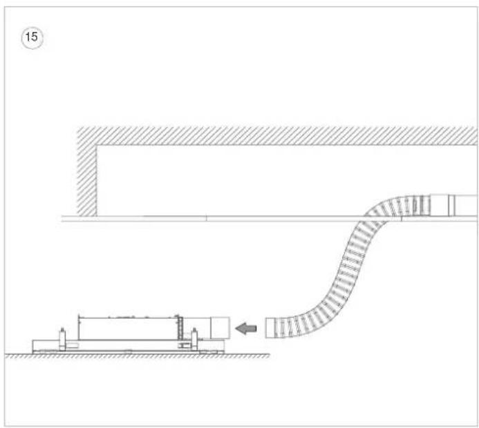
15 Place the cooker hood as close as possible to the cut-out opening and connect the flexible duct to the sensor kit. Use tape for an airtight connection.
16 Put the plug into the socket.
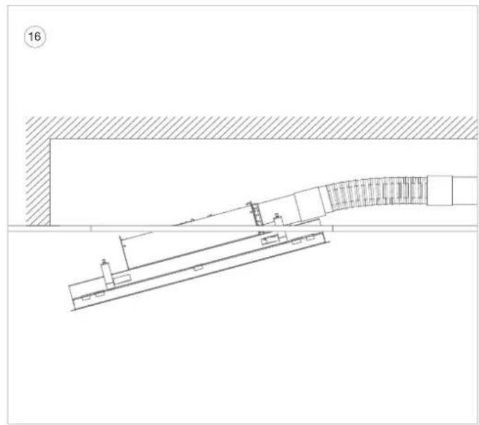
Push the ceiling unit by its edges (not on the bottom panel) at an angle upwards into the cut-out opening and click it into place with the clamping springs.

It push on the bottom panel!
The ceiling unit will now remain suspended in place.
17 Tighten the 4 clamping screws by hand to permanently secure the ceiling unit (caution: do not tighten too hard in plasterboard).
The cooker hood is now ready for use.
NL
Installation with exhaust opening to FRONT/REAR
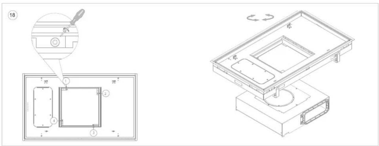
The appliance can only be installed with the exhaust direction towards the front/rear if there is a free space of approx. 25cm (distance Y in drawing 15) at the front and back of the cooker hood to slide the motor unit up during installation.
18
- Open the bottom panel and remove the grease filters from the cooker hood. Note: For easier installation, the bottom panel can be removed from the cooker hood.
- Loosen the 4 screws in accordance with the drawing. The motor unit is now detached.
- Turn the motor unit until the exhaust opening is to the front or rear and screw the motor unit back on using the 4 screws.
- Do not replace the grease filters yet. Close the bottom panel (if applicable).
- Click the connection piece (6810.030) onto the motor housing and screw in 4 screws for fixation (906.116).
Fierasier installation, the bottom panel can be removed from the cooker hood.
19
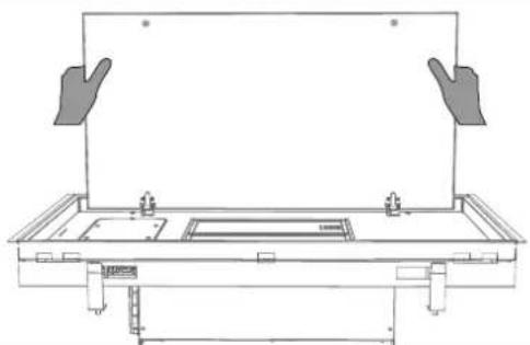
19 Removing and replacing the bottom panel
If the bottom plate is to be removed from the cooker hood for installation, proceed as follows:
-
Grasp the bottom panel at the left and right ends.
-
Slowly tilt the bottom panel downwards and continue to hold it in place.
-
As soon as the bottom panel is at a 90° angle downwards, the bottom panel can be slid to the right to remove it from the hinges. Here you will feel some resistance. Do this with caution to prevent damage to the cooker hood. Make sure you hold the bottom panel securely at all times.
-
T o replace the bottom panel, grasp the bottom panel at the left and right ends and hold it in place. Make sure you hold the bottom panel securely at all times.
-
Hold the bottom panel in a 90° angle downwards and slide the bottom panel to the left over the hinges until you notice a click.
-
The bottom panel cannot be closed if the bottom panel is not fully positioned over the hinges.
The bottom panel can then be closed.
To simplify the installation, we recommend using flexible flat exhaust ducting for the last section between the flat ductwork and the cooker hood. This is available as accessory from Novy (906,408).
Make sure that after installation, the flexible flat duct is not bend in a S-curve (= overlap) between the cooker hood and the flat duct work. This increases the pressure loss in the duct and has a negative effect on the efficiency of the cooker hood.
Overlap can be avoided by observing the following clearance between the end of the flat ductwork and the edge of the cut-out opening in the ceiling:
-
Model 6910 / 6911 / 6912 - minimum 500mm and maximum 520mm (X)
-
Model 6920 / 6921 / 6922 - minimum 500mm and maximum 520mm (X)
Connect the flexible flat duct (906.408) to the flat ductwork using a connection piece (906.402 not supplied). Use tape for an airtight connection. Pay attention to the required free space between the flat ductwork and the cut-out opening.
NL
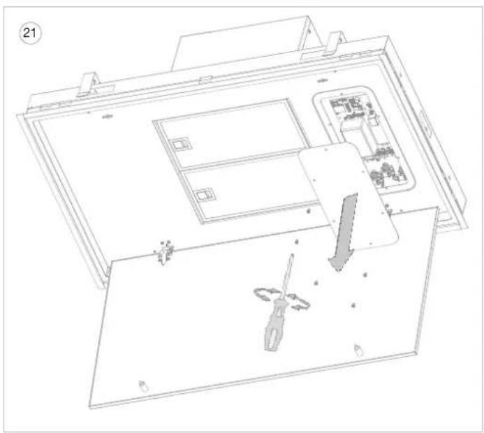
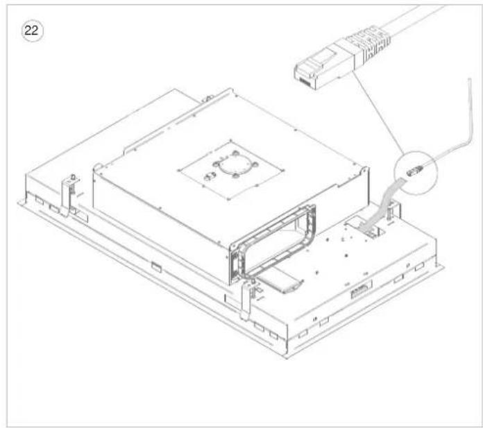
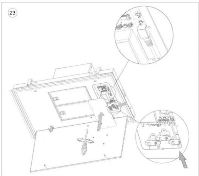
Cafon, do not perform any of the following operations while the unit is energised. Make sure that the power is off or that the plug of the cooker hood is unplugged.
21 Open the bottom panel of the cooker hood and remove the 6 screws (TX15) from the service hatch.
After this, the circuit board of the cooker hood is visible.
22 Route the supplied UTP cable (99004008) from above through the indicated opening so that the cable exits at the circuit board.
23 Connect the RJ45 connector of the UTP cable into the indicated connector on the circuit board. Fix the UTP cable in the indicated strain relief.
Then replace the service hatch and fix with the 6 screws (TX15).
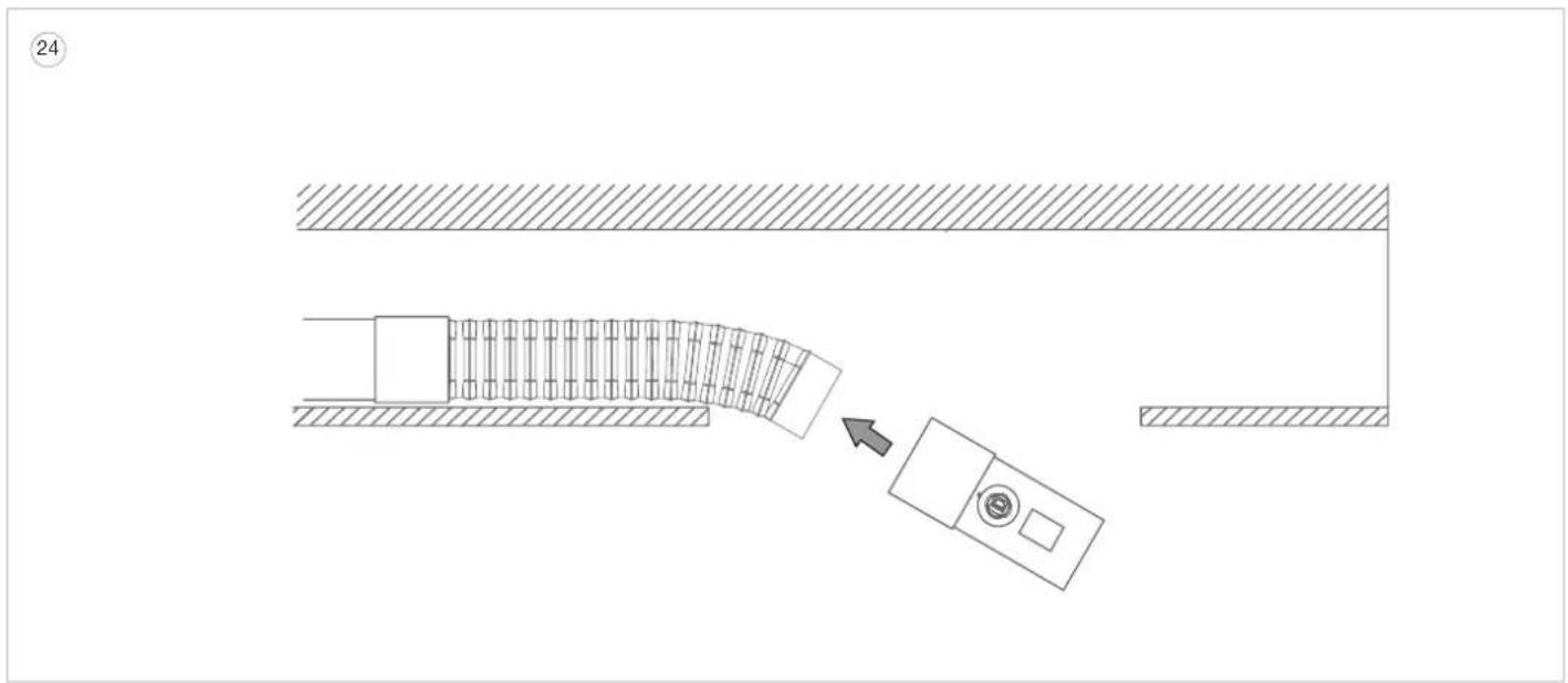
24 Connect the sensor kit with the supplied connection piece (906.402) to the flexible flat exhaust duct (906.408), paying attention to the direction of the airflow as indicated on the sticker of the Novy Sense sensor. The arrow must pointed downstream. Use tape for an airtight connection.
Place the complete assembly above the ceiling.
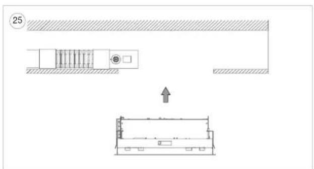
NL
Put the plug into the socket.
Caution, do not install under voltage. Make sure that the power is off at the socket.
e
Push the ceiling unit by its edges (not on the bottom panel) upwards into the cut-out opening and click it into place with the clamping springs.

push on the bottom panel!
The ceiling unit will now remain suspended in place.
26 Tighten the 4 clamping screws by hand to permanently secure the ceiling unit (caution: do not tighten too hard in plasterboard).
27

tion, plug is in the socket. Only carry the following actions if the power is off a socket.
-
Open the bottom panel and remove the grease filters from the cooker hood. (if applicable).
-
Loosen the 4 screws in accordance with the drawing. The motor unit is now detached
-
Slide the motor unit off the ductwork (approx. 25cm ) so that there is a free opening to the false ceiling.
-
Connect the cable from the sensor kit to the connector socket in the sensor kit.
-
Connect the sensor kit to the connection piece (6810.030) of the motor unit and use tape for an airtight connection.
-
Slide the motor unit back into place, making sure that the cable of the sensor kit is not caught between the housing of the cooker hood and the motor unit.
-
Screw the motor unit back on using the 4 screws.
-
Reinstall the bottom panel (if applicable), place the grease filters in the ceiling unit and close the bottom panel.
-
Restore power to the socket.
The cooker hood is now ready for use.
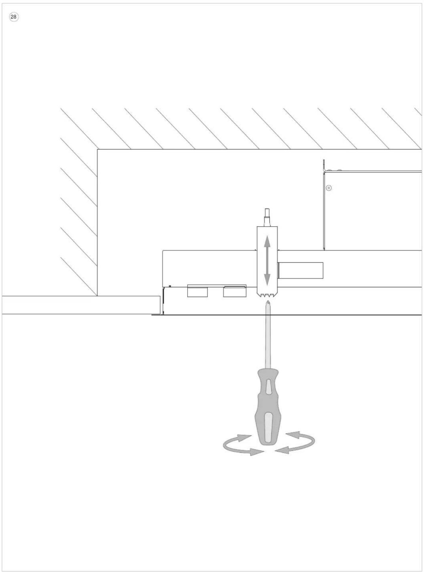
NL
For ALL exhaust directions
Dismantling the ceiling unit
Before dismantling, protect the hob with, for example, cardboard or a cloth in case a screw or clamp falls down.
Perform the following actions only when the power is off at the wall socket.
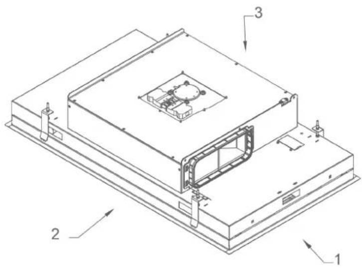
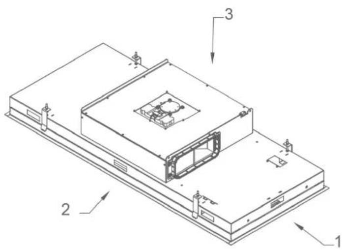
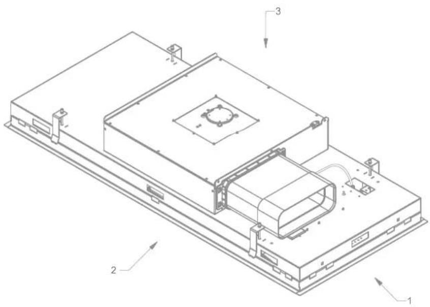
To dismantle the ceiling unit, first disconnect the motor unit from the cooker hood housing before dismantling the cooker hood (see drawing 2).
Next, the 4 clamping screws need to be fully unscrewed. Once these are unscrewed, the ceiling unit will come down. Please note that the motor unit lies loose on the housing of the cooker hood.
Please note that the unscrewed clamping springs can fall down.
NL MONTAGE NOVY Input/output module 990.036 ZONDER Novy Sense sensor
Carefully read the safety and installation instructions of this accessory and of the cooker hood with which it can be combined before installing and using it.
Caution, do not perform any of the following operations while the unit is energised. Make sure that the power is off or that the plug of the cooker hood is unplugged.
1 Open the bottom panel of the cooker hood and remove the 6 screws (TX15) from the service hatch.
After this, the circuit board of the cooker hood is visible.
2 Route the supplied UTP cable (99004008) from above through the indicated opening so that the cable exits at the circuit board.
3 Connect the RJ45 connector of the UTP cable into the indicated connector on the circuit board. Fix the UTP cable in the indicated strain relief.
Then replace the service hatch and fix with the 6 screws (TX15).
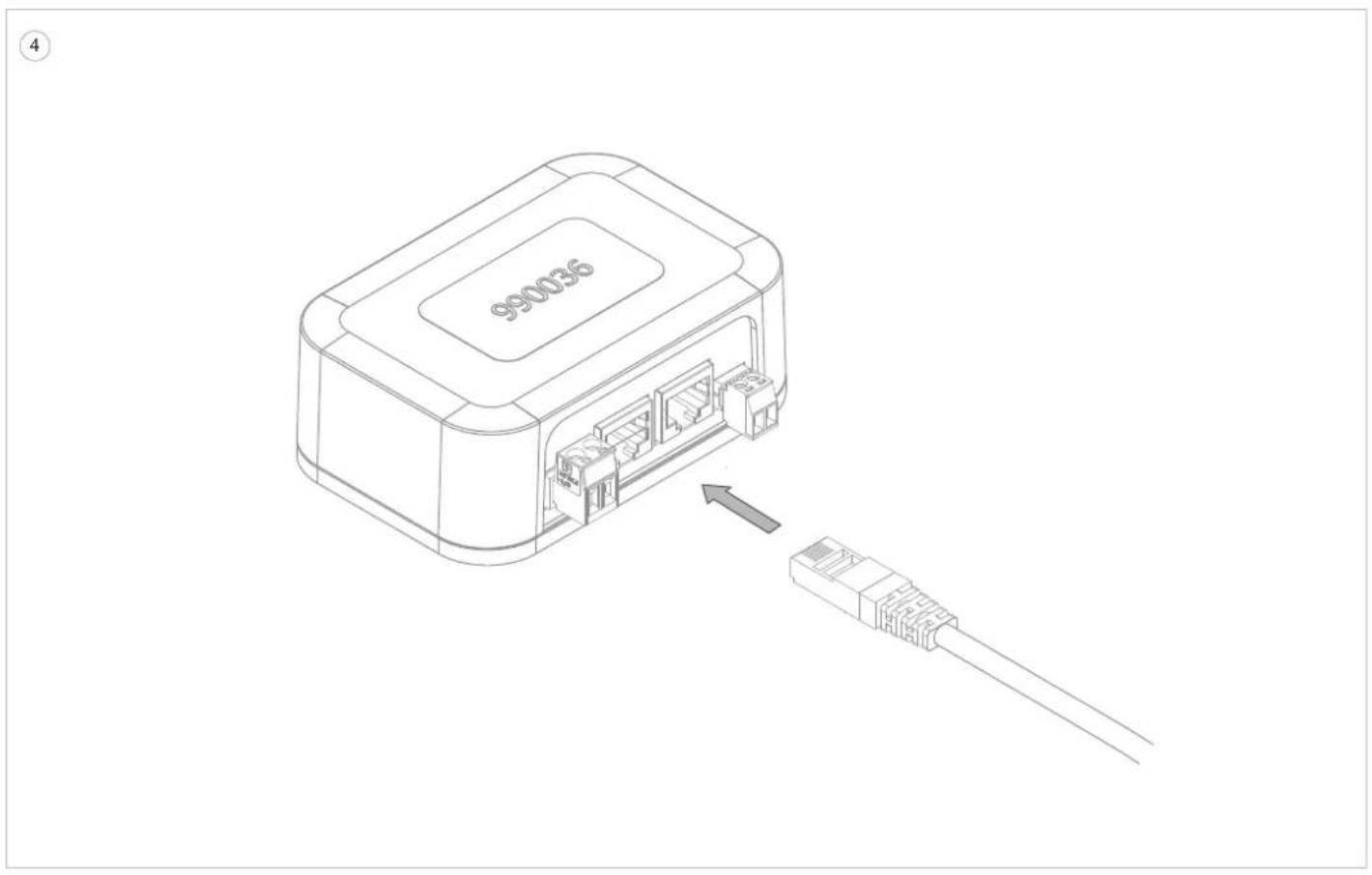
NL
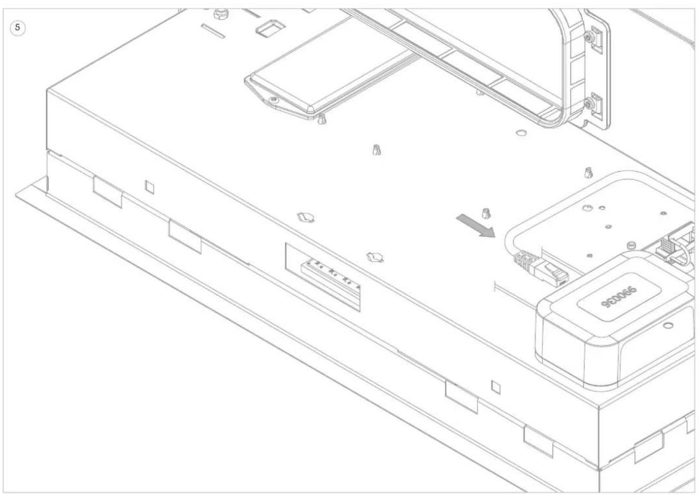
Place the RJ45 connector of the UTP cable coming from the cooker hood in one of the two RJ45 connector inputs of the input / output module 990.036.
Use the tape supplied (906292) to fixate the input/output module to the housing of the cooker hood. First degrease the surface to be glued with the included degreasing cloth (661057). Avoid blocking the openings for electrical connections in the housing of the cooker hood.
Check and connect the other connections of the module according to your installation situation (see electrical diagram in manual of Novy input / output module 990036).
NL MONTAGE NOVY Input/output module 990.036 MET Novy Sense sensor
Carefully read the safety and installation instructions of this accessory and of the cooker hood with which it can be combined before installing and using it.
Cafton, do not perform any of the following operations while the unit is energised. Make sure that the power is off or that the plug of the cooker hood is unplugged.
If the UTP cable of the sensor kit is already connected to the cooker hood; remove the RJ45 connector from the connector socket of the sensor kit. If not applicable, go to step 2 directly.
2 Open the bottom panel of the cooker hood and remove the 6 screws (TX15) from the service hatch. After this, the circuit board of the cooker hood is visible.
3 Route the supplied UTP cable (99004008) from above through the indicated opening so that the cable exits at the circuit board.
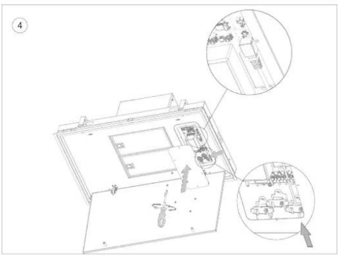
NL
Connect the RJ45 connector of the UTP cable into the indicated connector on the circuit board. Fix the UTP cable in the indicated strain relief.
Then replace the service hatch and fix with the 6 screws (TX15).
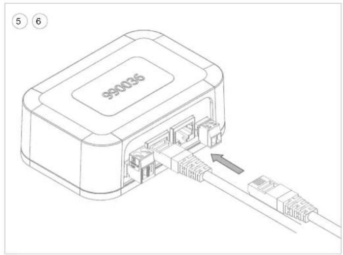
5 Place the RJ45 connector of the UTP cable coming from the cooker hood in one of the two RJ45 connector inputs of the input / output module 990036.
6 Then insert the RJ45 connector (not with angled connector) of the supplied separate UTP cable (99003607) into the other RJ45 connector input of the input / output module 990.036.
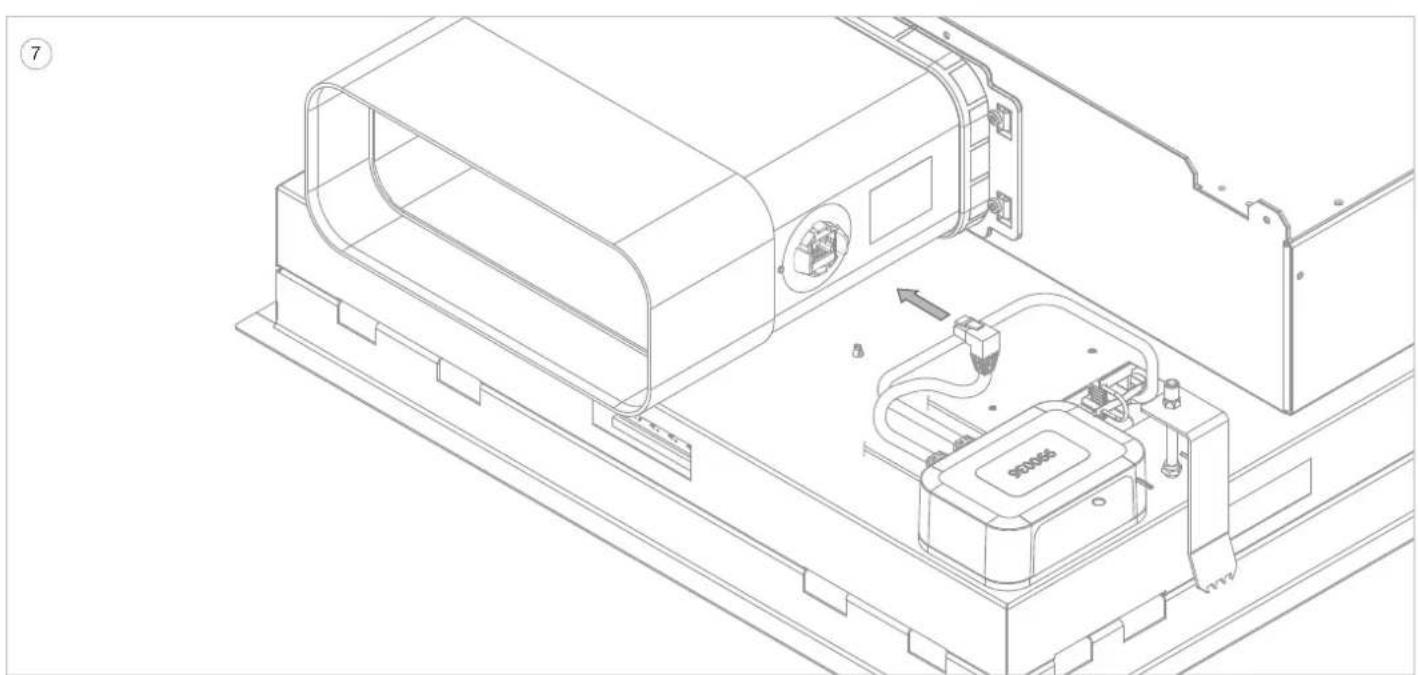
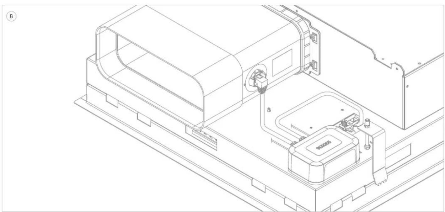
⑦ Insert the RJ45 angled connector of the supplied separate UTP cable 999003607) into the connector socket of the sensor kit.
Use the tape supplied (182151) to fixate the input/output module to the housing of the cooker hood. First degrease the surface to be glued with the included degreasing cloth (661057). Avoid blocking the openings for electrical connections in the housing of the cooker hood.
Check and connect the other connections of the module according to your installation situation (see electrical diagram in manual of Novy input / output module 990036).
3
4
1
2
3
4
6910, 6911, 6912
MET/AVEC/MIT/WITH Novy Sense sensor
1
2
3
4
6920, 6921, 6922
MET/AVEC/MIT/WH Novy Sense sensor
3
NOVY nv behoudt zich hetrecht voor te allen tijde en zonder voorbehoud de constructie en de prijzen vanhaar producten te wizigen. NOVY SA se reserve le croit de modifier à tout moment et sans reserve la fabrication et les prix de ses produits. Die NOVY AG behalt sich das Recht vor, zu jeder Zeit und ohne Vorbehalt die Konstruktion und die Preisierhrupekte zu andern. NOVY nv reserves the right at any time and without reservation to change the structure and the prices of its products.
NOVY
NOVY nv
Noordlaan 6
B-8520 KUURNE
Tel.056/36.51.00
Fax 056/35.32.51
E-mail: novy@novy.com
www.novy.com
France: Tel: 0320.940662


- 1 SAFETY AND ASSEMBLY REGULATIONS
- INGS BEFORE INSTALLATION
- ATION INSTRUCTIONS FOR THE APPLIANCE
- ST OR RECIRCULATION
- THE EXHAUST DUCT
- INSTALLATION INSTRUCTIONS FOR THE OUTLET
- 2 ACCESSORIES
- NOVY SENSE SENSOR
- FLEXIBLE DUCT
- RECIRCULATION
- ACCESSORIES FLAT EXHAUST DUCT
- ACCESSORIES CIRCULAR EXHAUST TUBE
- GENERAL ACCESSORIES
- INTOUCH
- WINDOW SWITCH
- NL
- NL 3 INSTALLATIE
- ALGEMEEN
- INSTALLATION WITH EXHAUST OPENING TO THE RIGHT
- INSTALLATION WITH EXHAUST OPENING TO THE LEFT
- INSTALLATION WITH EXHAUST OPENING TO FRONT/REAR
- 19 REMOVING AND REPLACING THE BOTTOM PANEL
- FOR ALL EXHAUST DIRECTIONS
- DISMANTLING THE CEILING UNIT
- NOVY
- NOVY NV
Brand : NOVY
Model : Pureline Pro Compact 6921
Category : Range hood