SmartOnline SUINT2000XLCD - Uninterruptible power supply Tripp Lite - Free user manual and instructions
Find the device manual for free SmartOnline SUINT2000XLCD Tripp Lite in PDF.
Download the instructions for your Uninterruptible power supply in PDF format for free! Find your manual SmartOnline SUINT2000XLCD - Tripp Lite and take your electronic device back in hand. On this page are published all the documents necessary for the use of your device. SmartOnline SUINT2000XLCD by Tripp Lite.
USER MANUAL SmartOnline SUINT2000XLCD Tripp Lite
9.1 Additional Power Management Features ............. 26
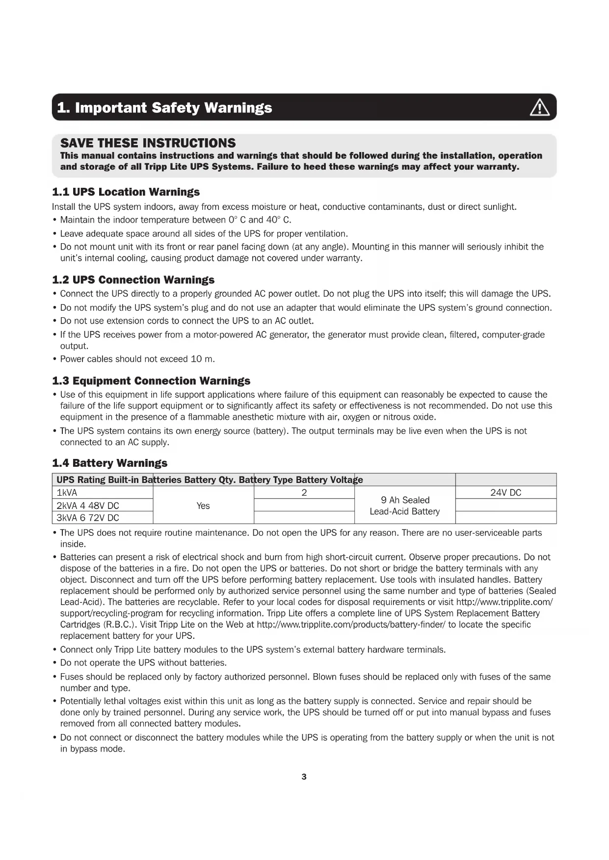
SAVE THESE INSTRUCTIONS
This manual contains instructions and warnings that should be followed during the installation, operation and storage of all Tripp Lite UPS Systems. Failure to heed these warnings may affect your warranty.
1.1 UPS Location Warnings
Install the UPS system indoors, away from excess moisture or heat, conductive contaminants, dust or direct sunlight.
- Maintain the indoor temperature between 0° C and 40° C.
- Leave adequate space around all sides of the UPS for proper ventilation.
- Do not mount unit with its front or rear panel facing down (at any angle). Mounting in this manner will seriously inhibit the unit’s internal cooling, causing product damage not covered under warranty.
1.2 UPS Connection Warnings
- Connect the UPS directly to a properly grounded AC power outlet. Do not plug the UPS into itself; this will damage the UPS.
- Do not modify the UPS system’s plug and do not use an adapter that would eliminate the UPS system’s ground connection.
- Do not use extension cords to connect the UPS to an AC outlet.
- If the UPS receives power from a motor-powered AC generator, the generator must provide clean, filtered, computer-grade output.
- Power cables should not exceed 10 m.
1.3 Equipment Connection Warnings
- Use of this equipment in life support applications where failure of this equipment can reasonably be expected to cause the failure of the life support equipment or to significantly affect its safety or effectiveness is not recommended. Do not use this equipment in the presence of a flammable anesthetic mixture with air, oxygen or nitrous oxide.
- The UPS system contains its own energy source (battery). The output terminals may be live even when the UPS is not connected to an AC supply.
1.4 Battery Warnings
UPS Rating Built-in Batteries Battery Qty. Battery Type Battery Voltage 1kVA Yes
- The UPS does not require routine maintenance. Do not open the UPS for any reason. There are no user-serviceable parts inside.
- Batteries can present a risk of electrical shock and burn from high short-circuit current. Observe proper precautions. Do not dispose of the batteries in a fire. Do not open the UPS or batteries. Do not short or bridge the battery terminals with any object. Disconnect and turn off the UPS before performing battery replacement. Use tools with insulated handles. Battery replacement should be performed only by authorized service personnel using the same number and type of batteries (Sealed Lead-Acid). The batteries are recyclable. Refer to your local codes for disposal requirements or visit http://www.tripplite.com/ support/recycling-program for recycling information. Tripp Lite offers a complete line of UPS System Replacement Battery Cartridges (R.B.C.). Visit Tripp Lite on the Web at http://www.tripplite.com/products/battery-finder/ to locate the specific replacement battery for your UPS.
- Connect only Tripp Lite battery modules to the UPS system’s external battery hardware terminals.
- Do not operate the UPS without batteries.
- Fuses should be replaced only by factory authorized personnel. Blown fuses should be replaced only with fuses of the same number and type.
- Potentially lethal voltages exist within this unit as long as the battery supply is connected. Service and repair should be done only by trained personnel. During any service work, the UPS should be turned off or put into manual bypass and fuses removed from all connected battery modules.
- Do not connect or disconnect the battery modules while the UPS is operating from the battery supply or when the unit is not in bypass mode.4
Prior to installation If the UPS needs to be stored prior to installation, it should be placed in a dry area. The allowable storage temperature is between -15°C and 50°C. After usage Press the OFF button, make sure the UPS is shut down, disconnect the UPS from the utility power, remove all equipment from the UPS, and store the UPS in a dry and well-ventilated area at a temperature between -15°C and 50°C. Idle batteries must be recharged fully approximately every three months if the UPS needs to be stored for an extended period of time. The charging time must not be less than 24 hours each time. Note: After storage and before start-up of the UPS, allow the UPS to adjust to room temperature (20° to 25°C) for at least one hour to avoid moisture condensation inside the UPS.
2.1 General Overview
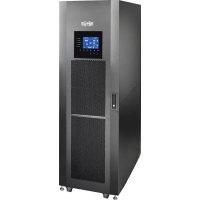
Tripp Lite’s SUINT-Series UPS is a VFI (voltage and frequency independent) true on-line double-conversion UPS, providing reliable and consistent sine-wave quality power to your electronic equipment. Designed to the highest quality with modern IGBT technology, SUINT-Series UPS systems delivers a secure, reliable and uninterrupted supply of clean power to your critical loads. Developed with a variety of ratings and a compact footprint, the SUINT-Series delivers a high-output power factor and high operating efficiency, providing more actual power to the attached load.
SUINT3000XLCD Item SUINT1000XLCD SUINT2000XLCD / SUINT3000XLCD UPS System 1 Pc. 1 Pc. Owner's Manual 1 Pc. 1 Pc. IEC to IEC Jumpers 2 Pc. 3 Pc. USB Cable 1 Pc. 1 Pc. RS232 Cable 1 Pc. 1 Pc. Note: 1. Inspect the UPS system for damage after unpacking it. If there is any damage or anything is missing, immediately contact Tripp Lite Tech Support. 2. If the UPS needs to be returned, carefully repack the UPS and all of the accessories using the original packing material that came with the unit. It is recommended to retain all original packing materials. Model-Specific Accessories (Optional)* Model SUINT1000XLCD SUINT2000XLCD SUINT3000XLCD External Battery Pack (LIMIT 1) BP24V15RT2U or BP24V28-2U BP48V24-2U or BP24V27-2US BP72V15-2U or BP72V18-2US External Battery Pack (NO LIMIT) BP24V70RT3U BP48V60RT3U BP72V28RT3U
- Visit the specification page for your UPS system at www.tripplite.com for detailed extended runtime data and additional accessory options.
EXTERNAL BATTERY CONFIGURATION NOTE
If external battery packs are to be used with this UPS, install them following the mounting/installation documentation included with each battery pack. External battery pack installation requires the UPS be configured via Tripp Lite’s EXTERNAL BATTERY CONFIGURATION software, downloadable from http://www.tripplite.com/bpconfig (for all external runtime configurations). This UPS is factory programmed with discharge curves and charging profiles for two basic external battery pack configurations accessible using the UPS front panel LCD interface. Additional battery pack options using larger or multiple external battery packs are also supported, but require configuration using Tripp Lite’s EXTERNAL BATTERY CONFIGURATION software and a serial port connection to the UPS. See 5.7 External Battery Type Selection Mode to determine which method applies to your external battery pack configuration.6
1. ON (green): Output available
1. ON: The UPS detects an internal fault or an environmental fault. Refer to 3.3 LCD Readout for more information.
2. Flashing: The UPS has the following warning message(s):
a. : There is no battery or battery replacement is needed. b. : The UPS is overloaded.
3.2 Multi-Function Buttons
ON: The button has four functions. Refer to the following for detailed information:
- In standby mode, press and hold the button for 3 seconds. Release it after one beep. The UPS will run in on- line mode.
- Cold start: When there is no AC input, press and hold the button for 3 seconds. Release it after one beep. The UPS will start up in battery mode.
2. Battery Test: A battery test may only be executed in on-line mode.
- To manually test the battery, press and hold the button for 3 seconds. Release it after one beep. The UPS will transfer to battery mode and perform a 10-second battery test. If the test result is normal, the LCD will show ‘PAS’ and the UPS will return to on-line mode. If the test result is abnormal, the LCD will show ‘bAd’, the LED will flash and the warning icon and no-battery/battery replacement icon will illuminate. The UPS will return to on-line mode.
3. Alarm Mute: When the alarm is on, press the button for 0.1 second to mute the alarm. The alarm will unmute
automatically when a new alarm event occurs. Note: The alarm cannot be turned on manually after it has been disabled in setup.
(including 3.4 7-Segment Display)
OFF: The button has two functions. Refer to the following for detailed information:
- In on-line mode, press and hold the button for 3 seconds. Release it after one beep. The inverter will be off and the UPS will transfer to standby mode. The UPS will keep charging the batteries in standby mode even though the button has been pressed. To fully turn off the UPS, it is advised to unplug the input power cord.
- In battery mode, press and hold the button for 3 seconds. Release it after one beep. The UPS will turn off its output.
When the UPS has a fault condition, press and hold the button for 3 seconds. Release it after one beep. The UPS will clear the fault condition and return to standby mode. The LCD will show the relevant error code. For error code information, refer to 3.3 LCD Readout. SETUP: The button has two functions. Refer to the following for detailed information:
Press the button for 0.1 second to go to the next display.
2. Entering the setup menu:
Press the button for 3 seconds and the UPS will enter the setup menu. For more information, refer to 6.1 Setup Menu. Please note that only qualified service personnel can perform setup actions. Note: When the backlight of the LCD is off, press any button to wake up the display and enable each button function.
1. ON: The AC input is within the acceptable input voltage range.
2. Flashing: The AC input is out of the acceptable input voltage range, but is still sufficient to let the unit operate in on-line mode.
3. OFF: The AC input is out of the acceptable input voltage range and is not sufficient to let the unit operate in on-
Note: In Setup Mode, the LED will be off, but output will still be available. Battery Power Icon: Indicates the battery power status.
2. OFF: Output is not supplied by the battery power.
Standby Mode Graph: Illuminates when the UPS is operating in standby mode. On-line Mode Graph: Illuminates when the UPS is operating in on-line mode. Frequency Converter Mode: Blinks when the UPS is operating in frequency conversion mode. Battery Mode Graph: Illuminates when the UPS is operating in battery mode. Bypass Mode Graph: Illuminates when the UPS is operating in bypass mode. ECO Mode Graph: Illuminates with “ECO” icon when the UPS is operating in eco mode. Note: Frequency conversion cannot be performed while in eco mode.
ECO8 Alarm Icon: Illuminates when the alarm is disabled. Warning Icon:
1. ON: The unit is shut down due to an internal or environmental fault. The error code will appear on the 7-segment
display. Refer to the following table for each error code and refer to 3.4 7-Segment Display for relevant 7-segment display information. Error Code Meaning E11 Charger Fault E13 Temperature Out of Range E14 +/- DC BUS High/Low E16 Inverter Fault E18 DC-DC Fault E19 Abnormal Output/Inverter Voltage E21 Output Short Circuit Sd1 RPO Shutdown Sd4 Battery Low Shutdown
2. Flashing: When the icon is flashing, it will be accompanied by other icon(s) to show the corresponding warning
message(s). a. : There is no battery or battery replacement is needed. b. : The UPS is overloaded. Load Level Bar Graph: Indicates the load level status.
1. ON: The bar graph illuminates according to the load level *1.
2. Flashing: The bar graph flashes when there is an overload situation.
Battery Level Bar Graph: Indicates the status of battery level.
1. ON: The bar graph illuminates according to the remaining battery capacity *1.
2. Flashing: The bar graph flashes when a low-battery situation occurs.
Note: *1 means that: <10%: no segment will illuminate. 10-29%: the first segment will illuminate. 30-49%: the first two segments will illuminate. 50-69%: the first three segments will illuminate. 70-89%: the first four segments will illuminate. 90-100%: all segments will illuminate.
Note: Read the text shown in Row A together with that in Column B to understand the display meaning.
1. IN & V: When the two illuminate together, it indicates input voltage.
2. IN & Hz: When the two illuminate together, it indicates input frequency.
1. OUT & V: When the two illuminate together, it indicates output voltage.
2. OUT & Hz: When the two illuminate together, it indicates output frequency.
RUN TIME RUNTIME & MIN: When the two illuminate together, it indicates the estimated remaining battery backup time. SET When the word ‘SET’ illuminates, it indicates the UPS is in setup mode. You can adjust the following through the LCD. For setup instructions, refer to the Setup Mode Flow Chart in Section 5.6.
1. When the word ‘TEST’ flashes, it means that the UPS is under self test.
2. When the words ‘TEST’ and ‘BATT’ flash together, it indicates the UPS is under battery self test.
1. BATT & %: When the two illuminate together, it indicates the remaining battery capacity.
2. BATT & V: When the two illuminate together, it indicates battery voltage.
1. LOAD & %: When the two illuminate together, it indicates how much of the UPS system’s total capacity is being used.
2. LOAD & KVA: When the two illuminate together, it indicates the total load in kVA.
3. LOAD & KW: When the two illuminate together, it indicates the total load in kW.
4. LOAD & % & : When (LOAD), unit (%) and icon flash together, it indicates the UPS has an overload situation.
Indicates frequency. kVA Indicates kVA.
Indicates kW. MIN Indicates minute.
Indicates the UPS system’s internal temperature.
3.5 Flow Chart of the 7-Segment Display
The following flow chart shows how to go through each display screen. Below, Standby Mode is used as an example. (Each of the display diagrams shown below is for reference only. Actual display depends on the UPS operation.) After this screen appears for approximately 10 seconds, the scrolling function will be active. The scrolling button is .
3. Operation Panel11
Press the button for 0.1 second to view the next display. Press the button for 0.1 second to view the next display. Press the button for 0.1 second to view the next display. Press the button for 0.1 second to view the next display. Press the button for 0.1 second to view the next display. Press the button for 0.1 second to view the next display. Press the button for 0.1 second to view the next display. Press the button for 0.1 second to view the next display. Press the button for 0.1 second to view the next display. Press the button for 0.1 second to view the next display. Press the button for 0.1 second to view the next display. Input Voltage Internal Temperature Input Frequency Estimated Runtime Output Voltage Battery Voltage Output Frequency % Battery Charge Load Percentage Load KVA Load KW
3. Operation Panel12
Accessory Slot Install an optional communication card in this slot to control and monitor the UPS system’s status remotely via a network. See tripplite.com for current network card options.
Output Sockets Connect to the loads.
USB Port, RS-232 Port Connects to the computer. You can monitor the UPS system locally via your computer by installing optional free PowerAlert software (downloadable from www.tripplite.com/poweralert).
Input Breaker This is the input power’s protective device and is for safety protection.
AC Input Socket Connects the UPS to the mains.
External Battery Connector Extend battery backup runtime with the addition of optional external battery.
1. Refer to 3. Operation Panel for details on using the operation panel and understanding the display meaning.
2. Each of the display diagrams shown in this chapter is for reference only. Actual display depends on the UPS operation.
After the UPS is connected to the AC utility, it will supply power to the UPS and the batteries will be charged. The default setting of the UPS is ‘STANDBY mode’.
In on-line mode, the connected loads are supplied by the inverter, which derives its power from the utility AC power. The UPS charges the batteries and provides power protection to its connected loads. Note: Also includes Frequency Conversion.
In bypass mode, the critical loads are directly supplied by the utility power and the batteries are charged.
Economy mode refers to an optional UPS configuration for reduced power consumption and heat output. A UPS in economy mode reduces power consumption by suspending the double-conversion (AC-to-DC / DC-to-AC) process whenever input power is already of high enough quality to pass through to connected equipment unchanged. The UPS will automatically switch back to on-line mode if input power quality deteriorates to ensure connected equipment receives high-quality power under all conditions.
When the UPS is operating during a power outage, the batteries’ DC power is inverted to AC and continues to provide power to the attached load(s) until a graceful shutdown can be completed. Tripp Lite’s PowerAlert
software is downloadable free of charge at www.tripplite.com/poweralert to monitor remaining battery capacity before and during a power outage. An optional SNMP card may be used to monitor and control the UPS across a network. Refer to www.tripplite.com/products/power-management-software-hardware~10 for more details on Tripp Lite’s SNMP management cards.
5. Operation Modes14
Press the scrolling button for more than 3 seconds to enter the setup menu. Note: Only qualified service personnel may perform setup actions. During setup, the following items can be adjusted:
For setup procedures, refer to the following:
1. Press the scrolling button for more than 3 seconds to enter the setup menu.
2. Press the scrolling button for 0.1 second to change the parameter.
3. Press the confirmation button for 0.1 second to confirm your parameter.
4. You can skip to the next setup item by pressing the cancel button for 0.1 second.
5. In setup, press the scrolling button for more than 3 seconds. The LCD will go to the original display.
6. In setup, if no button is pressed for more than 2 minutes, the LCD will exit from the setup menu and return to the original display. This UPS supports a variety of advanced configuration options that can be accessed via the front panel LCD screen. Configuration and information items include Inverter Voltage, Inverter Frequency, Frequency Conversion, Bypass Range, Economy Mode, Alarm Setup and Overload Alarm Setup. Some settings cannot be changed in certain operation modes. Refer to the table below for details: Setup Item Standby Mode On-line Mode Bypass Mode Battery Mode Inverter Voltage Yes No Yes No Inverter Frequency Yes No Yes No Frequency Converter Yes No Yes No Bypass Range Yes Yes Yes Yes Economy Mode Yes Yes Yes Yes Alarm Disable Yes Yes Yes Yes Overload Alarm Yes Yes Yes Yes Note: Only qualified service personnel may perform setup actions.
6. UPS Setup and Configuration15
Setup Flow Chart Original Display T>3 seconds T>3 seconds T>0.1ST=0.1S T>3 seconds T>0.1ST=0.1S T>3 seconds T>0.1ST=0.1ST>0.1S T>3 seconds T>0.1ST=0.1ST>0.1S T>3 seconds T>3 seconds T>0.1ST=0.1ST>0.1ST>0.1S Inverter Frequency Setup T>0.1ST=0.1S Frequency Converter Setup Bypass Range Setup Alarm Setup T>3 seconds T>0.1ST=0.1ST>0.1S Economy Mode Setup Overload Alarm Setup Inverter Voltage Setup T>0.1ST>0.1ST>0.1ST>0.1ST>0.1ST>0.1ST>0.1ST>0.1S
6. UPS Setup and Configuration16
6.2 Inverter Voltage Setup
OUTPUT VOLTAGE refers to the nominal output voltage of the UPS. This value is most commonly set to match the prevailing country or region-specific nominal voltage. Note: Certain voltage settings will cause automatic de-rating. See specifications on unit label for de-rating info. Inverter Voltage Setup for On-Line Mode / Battery Mode The inverter output voltage cannot be set under the on-line or battery modes. As a result, the LCD will display a warning message when the user attempts to set this item. Inverter Voltage Setup for Standby Mode / Bypass Mode Press the button for 0.1 second After 3 seconds Press the button for 0.1 second Press the button for 0.1 second Press the button for 0.1 second Press the button for 0.1 second Press the button for 0.1 second to advance to the next setup screen Press the button for 0.1 second to advance to the next setup screen Press the button for 0.1 second to advance to the next setup screen Set 220V Default Setting Set 240V
6. UPS Setup and Configuration17
6.3 Inverter Frequency Setup
OUTPUT FREQUENCY refers to the cycles per second (Hz) of UPS output power. To configure your UPS to convert frequency (default 50 Hz) from 50-to-60 Hz or 60-to-50 Hz, set the OUTPUT FREQUENCY to the desired setting. Inverter Frequency Setup for On-line Mode / Battery Mode The inverter output frequency cannot be set under the on-line or battery modes. As a result, the LCD will display a warning message when the user attempts to set this item. Inverter Frequency Setup for Standby Mode / Bypass Mode Press the button for 0.1 second After 3 seconds Press the button for 0.1 second Press the button for 0.1 second Press the button for 0.1 second to advance to the next setup screen Press the button for 0.1 second to advance to the next setup screen Set 60 Hz Default Setting
6. UPS Setup and Configuration18
6.4 Frequency Conversion Setup
During frequency converter mode, the bypass output is disabled and the inverter output frequency is fixed as the user’s inverter frequency setting. The inverter output frequency will not synchronize with the input frequency, even if input frequency is within +/-3 Hz of the inverter frequency setting. If there is an internal fault, the UPS will shut down directly without transferring to Bypass Mode. While in frequency converter mode, the output load will be derated by 30%. Note: Remove the load from the output before setting up frequency conversion. Do not attempt to change frequency with an attached load. Frequency Conversion Setup for On-line Mode / Battery Mode The frequency converter cannot be set under the on-line or battery modes. As a result, the LCD will display a warning message when the user attempts to set this item. Press the button for 0.1 second After 3 seconds Press the button for 0.1 second Press the button for 0.1 second Press the button for 0.1 second to advance to the next setup screen Press the button for 0.1 second to advance to the next setup screen Set ON Default Setting Frequency Conversion Setup for Standby Mode / Bypass Mode
6. UPS Setup and Configuration19
6.5 Bypass Range Setup
BYPASS RANGE: Sets the allowable voltage deviation (in percentage %) from nominal input voltage that is acceptable for the unit to go to bypass in a fault condition. If the voltage goes outside the range, the unit will not go to bypass. If the unit is already in bypass, it will turn the output off. The factory setting of 15% of 230V is compatible with the vast majority of networking equipment. Bypass Range Table 5% to 15% = -5%, +5% to -15%, +15% HI 1 = -20% to +15% HI 2 = -25% to +15% HI 3 = (120V to 226V) Press the button for 0.1 second Press the button for 0.1 second Press the button for 0.1 second Press the button for 0.1 second Press the button for 0.1 second Press the button for 0.1 second Press the button for 0.1 second Press the button for 0.1 second Press the button for 0.1 second to advance to the next setup screen Press the button for 0.1 second to advance to the next setup screen Press the button for 0.1 second to advance to the next setup screen Press the button for 0.1 second to advance to the next setup screen Set 5% (-5% ~ +5%) Set 6% (-6% ~ +6%) Set 7% (-7% ~ +7%) Set 8% (-8% ~ +8%)
6. UPS Setup and Configuration
Press the button for 0.1 second Press the button for 0.1 second Press the button for 0.1 second to advance to the next setup screen Set 9% (-9% ~ +9%)20 Press the button for 0.1 second Press the button for 0.1 second Press the button for 0.1 second Press the button for 0.1 second Press the button for 0.1 second Press the button for 0.1 second Press the button for 0.1 second Press the button for 0.1 second Press the button for 0.1 second Press the button for 0.1 second Press the button for 0.1 second to advance to the next setup screen Press the button for 0.1 second to advance to the next setup screen Press the button for 0.1 second to advance to the next setup screen Press the button for 0.1 second to advance to the next setup screen Press the button for 0.1 second to advance to the next setup screen Set 10% (-10% ~ +10%) Set 11% (-11% ~ +11%) Set 12% (-12% ~ +12%) Set 13% (-13% ~ +13%) Set 14% (-14% ~ +14%) Press the button for 0.1 second Press the button for 0.1 second Press the button for 0.1 second to advance to the next setup screen Set 15% (-15% ~ +15%)
6. UPS Setup and Configuration21
Press the button for 0.1 second Press the button for 0.1 second Press the button for 0.1 second Press the button for 0.1 second Press the button for 0.1 second Press the button for 0.1 second to advance to the next setup screen Press the button for 0.1 second to advance to the next setup screen Press the button for 0.1 second to advance to the next setup screen Set HI 1 (-20% ~ +20%) Set HI 2 (-25% ~ +25%) Set HI 3 (120V ~ 276V AC)
6. UPS Setup and Configuration22
The ALARM screen gives the user the ability to permanently enable or disable the UPS system’s audible alarm in case of an alarm event. The factory default of ON is ideal for most applications. Certain applications may require the alarm to be disabled, in which case the OFF option may be selected. Press the button for 0.1 second Press the button for 0.1 second Press the button for 0.1 second to advance to the next setup screen Press the button for 0.1 second to advance to the next setup screen Default Setting Set Disable
6. UPS Setup and Configuration
6.6 Economy Mode Setup
ECONOMY MODE is a UPS setting that enables enhanced efficiency and reduced BTU output by suspending double-conversion circuits whenever input power is already of sufficient quality to run connected equipment. If enabled, the UPS will run in economy mode when the voltage is within ±10% of nominal. If the voltage goes beyond the ±10% range, the UPS returns to on-line mode. Note: Economy Mode is off by default. Press the button for 0.1 second Press the button for 0.1 second Press the button for 0.1 second to advance to the next setup screen Press the button for 0.1 second to advance to the next setup screen Default Setting Set ECO ON23
6. UPS Setup and Configuration
6.8 Overload Alarm Setup
OVERLOAD ALARM refers to the point at which the UPS will sound its overload alarm. The factory setting of 105% will provide adequate overload warnings for most applications, but alternative values from 5% to the 105% default (in 10% intervals) are available for custom configurations. Press the button for 0.1 second Press the button for 0.1 second Press the button for 0.1 second Press the button for 0.1 second Press the button for 0.1 second Press the button for 0.1 second Press the button for 0.1 second Press the button for 0.1 second Press the button for 0.1 second Press the button for 0.1 second to advance to the next setup screen Press the button for 0.1 second to advance to the next setup screen Press the button for 0.1 second to advance to the next setup screen Press the button for 0.1 second to advance to the next setup screen Press the button for 0.1 second to advance to the next setup screen Default Setting Set 85% Set 95% Set 75% Set 65% Press the button for 0.1 second Press the button for 0.1 second Press the button for 0.1 second to advance to the next setup screen Set 55%24 Press the button for 0.1 second Press the button for 0.1 second Press the button for 0.1 second Press the button for 0.1 second Press the button for 0.1 second Press the button for 0.1 second Press the button for 0.1 second Press the button for 0.1 second Press the button for 0.1 second Press the button for 0.1 second to advance to the next setup screen Press the button for 0.1 second to advance to the next setup screen Press the button for 0.1 second to advance to the next setup screen Press the button for 0.1 second to advance to the next setup screen Press the button for 0.1 second to advance to the next setup screen Set 35% Set 45% Set 25% Set 15% Set 5%
6. UPS Setup and Configuration
6.9 External Battery Type Selection
EXTERNAL BATTERY TYPE refers to the ability for the UPS to become aware of which external battery pack is connected to the UPS. Setting the external battery configuration enhances the accuracy of the MINUTES RUNTIME countdown during power failure conditions. To update the runtime, you must use Tripp Lite’s EXTERNAL BATTERY CONFIGURATION TOOL software available for download at this link: http://www.tripplite.com/bpconfig.25 Note: Refer to 3. Operation Panel for details on the operation panel and the display meaning.
7.1 Turn-On Procedure
After the UPS is connected to the AC utility, the AC utility supplies power to the UPS. The UPS is initially set In Standby Mode. To turn on the UPS, press and hold the button for 3 seconds. Release it after one beep.
7.2 Cold Start Procedure
Even when there is no utility power, the UPS can be turned on. Press and hold the button for 3 seconds. Release it after one beep and the UPS will start up and run in Battery Mode.
7.3 Turn-Off Procedure
1. To turn off the UPS in On-line Mode, press and hold the button for 3 seconds. Release it after hearing one beep. The
inverter will turn off and the UPS will transfer to Standby Mode. The UPS will keep charging the batteries when the UPS is in Standby Mode, even though the button has been pressed. To fully turn off the UPS, unplug the input power cord.
2. To turn off the UPS in Battery Mode, press and hold the button for 3 seconds. Release it after hearing one beep. The
UPS will turn off its output. Battery Mode: The audible alarm beeps once every 2 seconds. Low Battery: The audible alarm beeps once every 0.5 second. Bad Battery/Battery Replacement*: The audible alarm beeps once every 2 seconds. Overload:
1. Overloaded 105-125%: The audible alarm beeps once every 2 seconds.
2. Overloaded 125-150%: The audible alarm beeps once every 0.5 second.
Fault: The audible alarm beeps continuously for 5 seconds if the UPS detects an internal fault.
- After reconnecting or replacing the batteries, it may take a short time for the UPS to switch off the alarm automatically. If, after a period of time, the audible alarm still exists, the user should manually initiate a battery test (press and hold the button for 3 seconds and release it after hearing one beep) to clear the alarm.
Software: Automatic shutdown software is available for use with Tripp Lite’s SUINT-Series UPS systems to allow for graceful and automatic shutdown of the connected loads in the event of an extended power failure. To download the appropriate PowerAlert software free of charge, visit www.tripplite.com/poweralert. Several optional accessories are available for Tripp Lite’s SUINT-Series UPS systems, including communication and remote monitoring, as well as associated battery cabinets for extended runtime. Refer to www.tripplite.com for all accessories currently available.
9.1 Additional Power Management Features
Via an optional network management card: Using a Tripp Lite network management card accessory, this UPS system supports most of the same configuration options available from the front panel LCD screen, as shown in Section 5, plus a few additional configurations. These additional configuration items are available via the network management card interface: BATTERY SAVE option enables automatic UPS power-off in battery mode when there is no need for continued operation. This option prevents unnecessary battery discharge by shutting off UPS power once the load level falls below a user- selectable percentage for five continuous minutes. Settings are available to enable shutdown at load levels between 5% and 95% (in 5% increments). The user may determine the ideal percentage setpoint by monitoring the UPS LCD load level screen for typical power consumption in both operating and shutdown modes. For example, if the connected equipment normally consumes 40-100% UPS capacity while operational, but drops to 3% once shutdown, a BATTERY SAVE percentage setting of 5% would be ideal. Once connected equipment power consumption falls below the selected percentage for 10 continuous minutes, the UPS will turn off automatically, preventing unnecessary battery discharge. The factory default for this option is DISABLED. BATTERY TEST refers to the ability of the UPS to perform regular self-tests of the battery system. During BATTERY TEST operation, the UPS will momentarily cycle to Battery Mode and alert users of potential UPS operational or battery-related fault conditions. The factory configuration of MONTHLY is ideal for most applications. Options for WEEKLY and DISABLE settings are also available. OFF MODE screen allows users to enable the UPS to provide output power when running in standby mode. The standby mode factory configuration is NO OUTPUT. Via RS-232 connection: This UPS supports configuration of economy mode, audible alarms and extended runtime configurations using PowerAlert software and a RS-232 connection to the UPS. These two parameters offer the same control options available through the front panel LCD interface. Refer to Section 5 for description and settings options. Via USB connection: This UPS supports configuration of the alarm using PowerAlert software and a USB connection to the UPS. Refer to Section 5 for description and settings options for Alarm Setup.27 If the UPS displays an error code, refer to the table below to diagnose and solve the problem: Error codes shown on the 7-segment Display: Error Code Meaning Possible Cause Solution E11 Charger Fault Charger is operating abnormally or not at all. Contact Tripp Lite Tech Support. E13 Temperature Out of Range The UPS temperature is out of range.
2. Decrease the loads.
3. Check whether the fan(s) run(s) normally.
E14 +/- DC BUS High/ Low The UPS is operating abnormally. Contact Tripp Lite Tech Support. E16 Inverter Fault The UPS is operating abnormally. Contact Tripp Lite Tech Support. E18 DC-DC Fault The UPS is operating abnormally. Contact Tripp Lite Tech Support. E19 Abnormal Output/ Inverter Voltage The UPS is operating abnormally. Contact Tripp Lite Tech Support. E21 Output Short Circuit Output has a short-circuit issue. 1. Check whether the output has a short- circuit issue.
2. Contact Tripp Lite Tech Support.
Sd1 RPO Shutdown Remote shutdown is executed. There is a 5 minute delay before shutdown is complete. After remote shutdown events are eliminated, follow the turn-on procedures to start the UPS. Sd4 Battery Low Shutdown The UPS transfers to run in battery mode due to AC utility abnormality; however, the battery power is almost depleted.
2. Run battery test.
3. Contact Tripp Lite Tech Support.
- The UPS is designed to supply power even when disconnected from utility power. Only authorized service personnel may access the interior of the UPS, after disconnecting the utility and DC power.
- Battery replacement should be performed only by authorized service personnel using the same number and type of batteries (sealed lead-acid).
- Do not disconnect the batteries while the UPS is in Battery mode.
- Disconnect the charging source prior to connecting or disconnecting terminals.
- Batteries can present a risk of electrical shock or burn from high short-circuit current.
- The following PRECAUTIONS should be observed:
1. Remove watches, rings or other metal objects.
2. Use tools with insulated handles.
3. Wear rubber gloves and rubber-soled footwear.
4. Do not lay tools or metal parts on top of batteries or battery cabinets.
5. Disconnect the charging source prior to connecting or disconnecting terminal.
6. Determine if the battery is inadvertently grounded. If it is, remove the source of the ground. Contact with any part of a grounded battery can result in electrical shock. The likelihood of such shock is reduced if such grounds are removed during installation and maintenance.
Cleaning Regularly clean the UPS, especially the vents and openings, to ensure air flows freely into the UPS to avoid overheating. If necessary, use compressed air to clean the vents and openings to prevent any object from blocking or covering these areas. Fan Higher temperatures shorten fan life. When the UPS is running, ensure each fan works normally and make sure air can move freely around and through the UPS. Note: Contact Tripp Lite Tech Support for more maintenance information. Do not perform maintenance if you are not qualified to do so. Regular Inspection Check the UPS every six months and inspect:
1. The UPS, LEDs and alarm function for normal operation.
2. Battery voltage; if battery voltage is too high or too low, see Troubleshooting table in Section 9.
Other problems that may occur: Problem Possible Cause Solution Overload The UPS is overloaded. Remove some of the connected loads. Bad Battery/Battery Replacement Batteries are damaged or battery life has expired. Contact Tripp Lite Tech Support. Abnormal Input (when the AC icon is flashing) The AC input voltage or frequency is out of the acceptable range.
1. Check whether the AC input voltage or
frequency is abnormal.
2. Contact Tripp Lite Tech Support.
Note: If a problem occurs, ensure mains input voltage is present. If all possible causes are eliminated but the alarm still appears, please contact Tripp Lite Tech Support. Have the following information ready when contacting Tripp Lite Tech Support:
- Unit information including model, serial number, etc.
- An exact description of the problem: the more detailed description of the problem, the better29
SUINT-Series UPS systems use sealed lead-acid batteries. Typical battery life is 3-5 years. However, actual battery life depends on temperature, usage and charging/discharging frequency. High temperature environments and high charging/discharging frequency will shorten the battery life. The UPS does not require maintenance by the user, but the batteries should be checked periodically. Follow the guidelines below to ensure a normal battery lifetime. Keep the usage temperature at 20° to 25°C. Idle batteries must be fully recharged every three months if the UPS is stored for an extended period of time. Fully charge the batteries (internal and external) until the Battery Level Bar Graph shown on the UPS system’s LCD is fully on. Note: Battery replacement should be performed only by qualified service personnel. If the UPS system’s internal batteries need to be replaced, please contact your Tripp Lite dealer. During battery replacement, the loads attached to the UPS will not be protected if input power fails.
11.4 Recycling the Used Battery
- Do not dispose of batteries in a fire. The batteries may explode. Proper disposal of batteries is required. The batteries are recyclable. Refer to your local codes for disposal requirements.
- Do not open or destroy the batteries. Escaping electrolytes may be toxic and can cause injury to the skin and eyes.
- Do not discard the UPS or the UPS batteries in the trash. Please recycle Tripp Lite Products. The batteries used in Tripp Lite products are sealed lead-acid batteries. These batteries are highly recyclable. Please refer to your local codes for disposal requirements. You can call Tripp Lite for recycling info at +1.773.869.1234. You can go to the Tripp Lite Website for up-to- date information on recycling the batteries or any Tripp Lite product. Please follow this link: http://www.tripplite.com/support/recycling-program/.
- Do not discard waste electrical or electronic equipment (WEEE) in the trash. For proper disposal, contact your local recycling/ reuse or hazardous waste center.
Model SUINT1000XLCD SUINT2000XLCD SUINT3000XLCD Power Rating* 1kVA/0.9KW 2kVA/1.8KW 3kVA/2.7KW Waveform Pure Sine Wave Input Nominal Voltage 220/230/240 Vac Voltage Range 176-280 Vac (100% load) Frequency 50/60 Hz ± 10 Hz Power Factor > 0.99 (full load) iTHD < 5% Connection C14 C14 C20 Output Power Factor 0.9 Voltage 220/230/240 Vac Voltage Regulation ± 2% (linear load) Frequency 50/60 Hz ± 0.05 Hz vTHD < 3% (linear load) Overload Capability < 105%: continuous; 105-125%: 1 minute; 126-150%: 30 seconds Crest Factor 3:1 Connections IEC C13 (x4) IEC C13 (x7) IEC C13 (X6), C19 (x1) Efficiency (at Full Load) Online Mode 91% 93% Economy Mode 96% Battery Battery Voltage 24V DC 48V DC 72V DC Battery Quantity 2 4 6 Backup Runtime 50% 13 min. 100% 5 min. 50% 11 min. 100% 3 min. 50% 10 min. 100% 3 min. Recharge Time 6 hours to 90% Audible Noise < 49 dBA < 52 dBA Display LED Indicators & LCD Readout Communication Interfaces Accessory Slot, USB Port, RS-232 Port Physical Dimensions (W×D×H) 145 x 320 x 225 mm 190 x 390 x 325 mm 190 x 390 x 325 mm Weight 9.5 kg 19.4 kg 25.8 kg Environment Operating Temperature 0-40°C Relative Humidity 5-95% (non-condensing) *Power capacity derated 30% when operating in frequency converter mode.31 Regulatory Compliance Identification Numbers For the purpose of regulatory compliance certifications and identification, your Tripp Lite product has been assigned a unique series number. The series num- ber can be found on the product nameplate label, along with all required approval markings and information. When requesting compliance information for this product, always refer to the series number. The series number should not be confused with the marketing name or model number of the product. WEEE Compliance Information for Tripp Lite Customers and Recyclers (European Union) Under the Waste Electrical and Electronic Equipment (WEEE) Directive and implementing regulations, when customers buy new electrical and electron- ic equipment from Tripp Lite they are entitled to:
- Send old equipment for recycling on a one-for-one, like-for-like basis (this varies depending on the country)
- Send the new equipment back for recycling when this ultimately becomes waste Tripp Lite has a policy of continuous improvement. Specifications are subject to change without notice. Photos and illustrations may differ slightly from actual products.