SmartOnline SV40KM2P3B - Uninterruptible power supply Tripp Lite - Free user manual and instructions
Find the device manual for free SmartOnline SV40KM2P3B Tripp Lite in PDF.
Download the instructions for your Uninterruptible power supply in PDF format for free! Find your manual SmartOnline SV40KM2P3B - Tripp Lite and take your electronic device back in hand. On this page are published all the documents necessary for the use of your device. SmartOnline SV40KM2P3B by Tripp Lite.
USER MANUAL SmartOnline SV40KM2P3B Tripp Lite
2.5 Safety Standards 5
4. Positioning and Pre-Installation 9
4.1 Important Safety Warning 9
4.2 Transportation 9
4.5 Unpacking the UPS 10
6.1 Operating Modes 12
7.2.5 External Battery Cabinet Connection 17
8.1 Transfer to Bypass via STS Module Connector 18
8.2 Transfer to Bypass via Control Panel 18
9.3.8 Events Screen 27
9.3.8.1 Current Events 27
9.4 Text Summaries and Explanations 28
10.2 Dry Contact Ports 30
14. UPS and Battery Storage; Battery Disposal 36
14.1 UPS and Battery Storage 36
14.2 Battery Disposal 36
15. Warranty and Product Registration 363
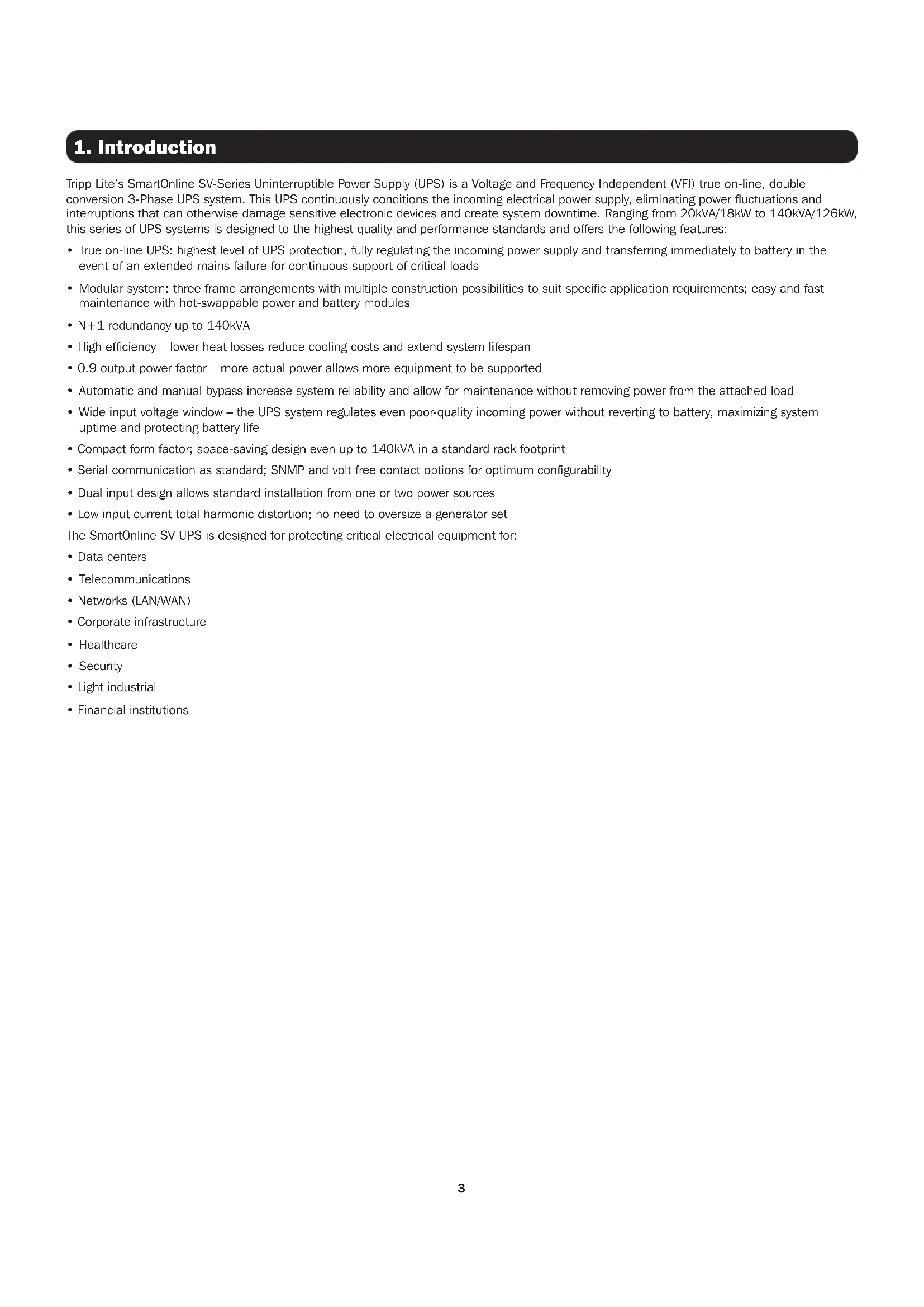
Tripp Lite’s SmartOnline SV-Series Uninterruptible Power Supply (UPS) is a Voltage and Frequency Independent (VFI) true on-line, double conversion 3-Phase UPS system. This UPS continuously conditions the incoming electrical power supply, eliminating power fluctuations and interruptions that can otherwise damage sensitive electronic devices and create system downtime. Ranging from 20kVA/18kW to 140kVA/126kW, this series of UPS systems is designed to the highest quality and performance standards and offers the following features:
- True on-line UPS: highest level of UPS protection, fully regulating the incoming power supply and transferring immediately to battery in the event of an extended mains failure for continuous support of critical loads
- Modular system: three frame arrangements with multiple construction possibilities to suit specific application requirements; easy and fast maintenance with hot-swappable power and battery modules
- N+1 redundancy up to 140kVA
- High efficiency – lower heat losses reduce cooling costs and extend system lifespan
- 0.9 output power factor – more actual power allows more equipment to be supported
- Automatic and manual bypass increase system reliability and allow for maintenance without removing power from the attached load
- Wide input voltage window – the UPS system regulates even poor-quality incoming power without reverting to battery, maximizing system uptime and protecting battery life
- Compact form factor; space-saving design even up to 140kVA in a standard rack footprint
- Serial communication as standard; SNMP and volt free contact options for optimum configurability
- Dual input design allows standard installation from one or two power sources
- Low input current total harmonic distortion; no need to oversize a generator set The SmartOnline SV UPS is designed for protecting critical electrical equipment for:
- Corporate infrastructure
SAVE THESE INSTRUCTIONS. This manual contains important instructions and warnings that should be followed during the installation, operation and maintenance of all Tripp Lite SmartOnline SV 3-phase UPS systems and batteries. Read all instructions thoroughly before attempting to move, install or operate the UPS. Failure to comply may invalidate the warranty and cause property damage and/or personal injury.
2.1 Location Warning
This UPS contains LETHAL VOLTAGES. All repairs, service and installation must be performed by AUTHORIZED SERVICE PERSONNEL ONLY. There are NO USER SERVICEABLE PARTS inside the UPS.
- SmartOnline SV UPS systems are designed for commercial and industrial application purposes only.
- Cabinets must be installed on a level floor suitable for computer or electronic equipment.
- The UPS cabinet is heavy. Closely follow unloading instructions to avoid the risk of injury.
- Install the UPS system in a controlled indoor environment, away from moisture, temperature extremes, flammable liquids and gasses, conductive contaminants, dust and direct sunlight. The system is not intended for outdoor use.
- Operate the UPS at indoor temperatures between 32° to 104°F (0° to 40°C) only. For best results, maintain indoor temperature between 63° to 77°F (17° to 25°C).
- Do not place any object on the UPS system, especially containers of liquid.
- Do not install the UPS with the front or rear panel facing down (at any angle). Mounting in this manner will seriously inhibit the unit’s internal cooling, causing product damage not covered under warranty.
- Do not tilt the UPS cabinet more than 10°.
- Do not attempt to unpack or move the UPS without assistance.
This equipment has been tested and found to comply with the limits for a Class A digital device, pursuant to part 15 of the FCC Rules. These limits are designed to provide reasonable protection against harmful interference when the equipment is operated in a commercial environment. This equipment generates, uses, and can radiate radio frequency energy and, if not installed and used in accordance with the instruction manual, may cause harmful interference to radio communications. Operation of this equipment in a residential area is likely to cause harmful interference in which case the user will be required to correct the interference at his own expense. Changes or modifications not expressly approved by the party responsible for compliance could void the user’s authority to operate the equipment.
2.3 Connection Warning
BEFORE WORKING ON THIS UPS
- Isolate the SmartOnline SV UPS.
- Check for hazardous voltages between all terminals, including the protective earth.
- Risk of Voltage Backfeed: The isolation device must be able to carry the UPS input current. The backfeed protection device should be VDE/EN/UL approved and rated 220V (L-N) / 380V (L-L), 630A (Large Frame) / 300A (Medium Frame) / 250A (Small Frame). Figure 2.1: Backfeed Protection Connections5
An authorized Tripp Lite engineer must perform the start-up of the UPS and a completed start-up form must be returned to Tripp Lite in order to activate the SmartOnline SV warranty. Please contact your local supplier or techsupport@tripplite.com for further details. To find your local contact, go to www.tripplite.com/support/contacts. This UPS contains LETHAL VOLTAGES. KEEP DOORS LOCKED AT ALL TIMES. All repairs, service and installation must be performed by AUTHORIZED SERVICE PERSONNEL ONLY. There are NO USER SERVICEABLE PARTS inside the UPS.
- Ensure all power is disconnected before performing installation or service.
- The UPS system contains its own energy source (battery). The output terminals may carry live voltage even when the UPS is disconnected from an AC source.
- Use of this equipment in life support applications where failure of this equipment can reasonably be expected to cause the failure of the life support equipment or to significantly affect its safety or effectiveness is not recommended.
- The Protective Earth Ground must be installed first prior to any power connections made to the equipment.
- Installation and wiring must be performed in accordance with local electrical laws and regulations.
- The AC disconnection device must break line and neutral conductors: four connectors for three phases (L1, L2, L3 and N).
- The DC disconnection device must break line with both the positive and negative conductors.
- A readily accessible, external disconnect device to the equipment shall be provided for the AC and DC supplies in the end installation.
This UPS contains LETHAL VOLTAGES. The UPS is designed to supply power even when disconnected from utility power. Only AUTHORIZED SERVICE PERSONNEL should access the interior of the UPS, after disconnecting the utility and DC power. Batteries present a risk of electrical shock and burns from high short-circuit current. Battery connection or replacement should be performed only by qualified service personnel, observing proper precautions. Turn off the UPS before connecting or disconnecting internal batteries. Use tools with insulated handles. Do not open the batteries. Do not short or bridge the battery terminals with any object.
- The batteries are recyclable. Refer to local codes for disposal requirements or visit http://www.tripplite.com/support/recycling-program for recycling information.
- Do not dispose of the batteries in a fire, mutilate the batteries or open the battery coverings. Escaping electrolytes may be toxic and cause injury to skin and eyes.
- Do not disconnect the batteries while the UPS is in battery mode.
- Disconnect the charging source prior to connecting or disconnecting terminals.
- The following precautions should be observed:
1. Remove watches, rings and other metal objects.
2. Use tools with insulated handles.
3. Wear rubber gloves and boots.
4. Do not lay tools or metal parts on top of batteries or battery cabinets.
5. Determine whether the battery is inadvertently grounded. If it is, remove the source of the ground. Contact with any part of a grounded battery can result in electric shock. The likelihood of an electric shock is reduced if such grounds are removed during installation and maintenance.
- Battery replacement should be performed only by authorized service personnel, using the same number and type of batteries (sealed lead acid).
- If the UPS system remains off for an extended period of time, it should be turned on periodically and the batteries should be fully charged. See Section 14.1 UPS and Battery Storage for battery storage recommendations. Failure to recharge the batteries may cause irreversible battery damage.
2.5 Safety Standards
Item Normative reference Uninterruptible power systems (UPS) UL 1778, CSA C22.2 No.107.3-14 Notes: Conducted FCC Part 15, Subpart B Class A Radiated FCC Part 15, Subpart B Class A6
(Medium/Large Frame)
58 in. (1475 mm) Figure 3.1: Dimensions Frame Selection Height Width Depth Small Frame (30U) 20-60kW with integrated batteries 58 in. (1475 mm) 23.64 in. (600 mm) 43.30 in. (1100 mm) Medium Frame (42U) 20-80kW with integrated batteries 79 in. (2010 mm) 23.64 in. (600 mm) 43.30 in. (1100 mm) Large Frame (42U) 20-140kW without battery 79 in. (2010 mm) 23.64 in. (600 mm) 43.30 in. (1100 mm)7
LED and LCD Control Panel
Battery Module/s (small and medium frame models; see Section 13. Technical Specifications for a full listing)
Battery Breaker (small and medium frame models; see Section 13. Technical Specifications for a full listing)
The modularity of the SmartOnline SV-Series allows three frame arrangements with multiple construction possibilities according to the user’s power rating and battery runtime requirements. The table below indicates the module capacity per frame. Refer to Section 13 Technical Specifications for detailed breakdown of maximum Power and Battery Modules per frame. Small Frame Medium Frame Large Frame Cabinet Height 30U 42U 42U Switch Module (built into frame)
STS Module (built into frame)
Max. Power Module 3 4 7+1* Max. Battery Module 3 4 N/A Note: Consider the wiring gauges and external battery space requirements for the large frame. Each battery module is comprised of four trays of batteries. Each tray contains 10 pieces 12V/9Ah battery. Four trays must be utilized per module; it is not possible to install partial modules.
- The large frame hosts up to 140kVA/126kW power capacity without batteries. An additional power module may be added for N+1 redundancy.
- The Switch/STS module is delivered with the frame; the power module, battery modules and WEBCARDLX are packaged separately. ** Medium frame *** Small frame9
4.1 Important Safety Warning
Read this manual thoroughly before undertaking any installation and wiring. An authorized Tripp Lite engineer must perform the start-up of the UPS and a completed start-up form must be returned to Tripp Lite in order to activate the SmartOnline SV warranty. Contact Tripp Lite at www. tripplite.com/support/contacts for further details.
WARNING The UPS is packed on a pallet suitable for handling with a forklift. If using a forklift or other equipment to move the UPS, ensure its load bearing capacity is sufficient to support the total packing weight of the UPS. The UPS is fixed on the pallet with four balance supports. When removing them, pay attention to the movement of the casters to avoid accidents. The UPS cabinet may be pushed forward or backwards only; it may not be moved sideways. The cabinet has a high center of gravity; take care to not tip or overturn the cabinet during transportation. If moving the UPS over long distance, use appropriate equipment such as a forklift. Do not move the UPS cabinet using its attached casters over long distances. Move the UPS cabinet in its original packaging until at the final destination site.
Inspect the packaging materials and UPS cabinet carefully upon delivery. Do not install a damaged UPS, connect it to a battery or to the utility. The packing box of the UPS is equipped with an anti-tilt device. Confirm the device does not indicate any shock or excess tilt during transit. If the device indicates there has been excessive shock or tilt, do not install and contact your local Tripp Lite representative.
4.4 Installation Environment
- The UPS is designed for indoor use only. Do not place or install the UPS in an outdoor area.
- When moving the UPS to its installation site, ensure all corridors, doors, gates, elevators, floors, etc. are able to accommodate and bear the combined weight of the UPS system, any associated battery cabinets and all handling equipment. See Section 13. Technical Specifications for UPS module combined weights.
- The installation site should have a dedicated AC circuit available, compatible with the UPS system’s input requirements. See Section 13. Technical Specifications for input specifications.
- Ensure the installation area has sufficient space for maintenance and ventilation of the UPS system.
- Maintain the installation area’s temperature below 86°F (30°C) and the humidity below 90%. The highest operating altitude is 6500 ft. (2000 m) above sea level. Please consider the derating values when operating the UPS over 3280 ft. (1000 m). The optimum operating temperature for the batteries is 77°F (25°C).
- The UPS should be located in an environment with clean air and adequate ventilation to maintain the ambient temperature within the UPS operating range.
- The UPS is air-cooled with the aid of internal fans. Do not cover the ventilation openings of the UPS system.
- Install the UPS in an area in which the walls, floors and ceilings are constructed with fireproof materials. The UPS is suitable for mounting on concrete or other non-combustible surfaces only.
or dry powder extinguisher in the installation area.
- Maintain a clearance of at least 48 in. (120 cm) from the top of the UPS for maintenance, cabling and ventilation.
- Maintain a clearance of at least 40 in. (100 cm) from the rear and front of the UPS for access and ventilation.
4. Positioning and Pre-Installation10
4. Positioning and Pre-Installation
4.5 Unpacking the UPS
1. Once the UPS system has arrived at the installation site, it may be removed from the packing box. Follow the unpacking procedure below to remove main carton (Figure 4.1) and protective materials (Figure 4.2). Figure 4.1 Figure 4.2 2. Place the ramp delivered in the packing box in front of the UPS cabinet and align the hole in the ramp to the metal stud on the pallet and lock into place (Figure 4.3). 3. Remove the four fixing plates (Figure 4.4) and loosen the leveling feet by rotating them counterclockwise, raising them above the level of the casters. The UPS cabinet may now be rolled off the pallet and down the ramp. At least three people should be present to move the UPS to the installation area, two to support either side of the UPS and a third to guide the UPS into its final location. 4. The casters are designed to move on a level surface over a short distance for final UPS placement. Do not move the UPS using the casters over long distances or across uneven surfaces. This could damage the casters and/or tip the UPS. 5. Once the UPS is in final position, rotate the leveling feet clockwise below the level of the casters to secure in place (Figure 4.5). Do not rest the UPS permanently on the casters. Figure 4.3 Figure 4.4 Figure 4.511
Rectifier: Converts AC from the utility into DC voltage and charges the battery. Inverter: Converts DC voltage into fully regulated, clean AC voltage to power the attached load. Regardless of the AC waveform from the utility, the load receives a clean, consistent sine wave with stable voltage and frequency. Automatic Bypass (Static Switch): Transfers the attached load to mains in case of overload or internal failure. The load is kept powered up as long as the mains power is available. Manual Bypass (Maintenance Breaker): User-operated physical switch. The user can transfer the load to bypass to perform UPS maintenance without powering down the load.12 Small- and Medium-Frame Units INPUT 1 INPUT 2 Figure 6.3For dual input installation, red, yellow and black wire jumpers must be removed as shown in Figure 6.3 (top rear view of cabinet).Large-Frame Units INPUT 1 BUSBAR INPUT 2 Figure 6.4For dual input installation, busbar jumpers must be removed as shown in Figure 6.4 (top view of cabinet).
Normal (Double Conversion, VFI)Power flows through the UPS rectifier and inverter. Voltage and frequency to the load is independent of voltage and frequency from the input. There are higher efficiency losses in this mode due to the double conversion process.
Output BreakerInverterRelayBattery BreakerRectifier Inverter STS BypassMain LoadECO ModeWhen utility power quality is stable, power can be diverted through the automatic bypass of the UPS. If the utility power goes out of tolerance or is lost, the UPS transfers quickly back to inverter to power the load in VFI mode. The result is improved efficiency and cost savings when power conditions are good.
The UPS can accept dual inputs for additional redundancy (e.g. in a server rack installation operating on dual AC feeds). When powering the UPS with dual AC feeds, first remove the jumpers, as shown below.Figure 6.1 Figure 6.213
The input breaker, maintenance bypass breaker and output breaker are located at the front of the Switch Module of the UPS system. The battery breaker and input/output wiring terminal blocks are at the rear of the Switch Module. To access the terminals from the back of the UPS, remove the protective Plexiglas
panel cover. Wiring installation must be made from the top of the UPS cabinet using the two terminal conduit covers provided. For connection details, refer to Figure 7.1 (large-frame terminal block shown). Figure 7.1 Function Description Output Block Connection to the supported load Includes R (L1), S (L2), T (L3) and Neutral terminals Alternate Input Block (Input 2) Alternate AC input source connection Includes R (L1), S (L2), T (L3) and Neutral terminals Main Input Block (Input 1) Primary AC input source connection Includes R (L1), S (L2), T (L3) and Neutral terminals Grounding Terminal For UPS grounding Includes one grounding terminal Battery Input Block For external battery connection Includes Positive (+), Negative (-) and Neutral (N) terminals
7.2 STS Module Installation
The STS Module and Switch Module are pre-installed in the frame. STS Module comprises:
- Communication Circuit (including SNMP, Serial [RS-232])
- Internal Static Transfer Switch
- Breaker(s) Power and Battery Modules can be added according to the user’s requirements. The tables on the following page indicate the maximum current and cable configurations per assembly. Note: Internal battery modules for Small- and Medium-Frame systems only.14
Ensure all Power Modules contain identical firmware versions prior to installation. Each Power Module capacity is 20kVA/18kW and comprises:
- Control Circuit Figure 7.2 The hot-swappable Power Module allows for quick maintenance and system expansion. A latch located at the front of each module fixes and locks the module in its assigned slot. To install the Power Module, follow the procedure below. 1. Using the DIP switch on the front panel of each Power Module, set the module ID (0-7). The module ID should be exclusive per module. Note: The default position is 0 for all DIP switches. Module ID Module DIP Switch 0 POWER 1 POWER 2 POWER 3 POWER 4 POWER 5 POWER 6 POWER 7 POWER Table 7.1 2. Place the ready switch on the front panel of the Power Module in the unlocked position by rotating the knob counterclockwise. 3. Remove blanking panel and insert Power Module into its identified frame position and slide into cabinet (retain the four screws to install Power Module in step 4).16
4. Secure the module to the frame via the fixing bracket using the four screws. Ensure both sides of the Power Module are secured to the frame.
5. Place the ready switch into the locked position by rotating the knob clockwise.
Note: For initial startup and powering on the UPS, refer to Section 9.1 Control Panel – Introduction After the UPS has been successfully powered ON, refer to
Section 9.3.6.2 System to adjust total power and redundancy settings of the UPS based on power modules installed.
If additional power modules are being installed after initial startup, you may skip Section 9.1 and go to Section 9.3.6.2 to adjust total power and redundancy settings. The Power Module’s LED indicator displays its operational status as follows No. Behavior LED Display 1 Indicates the system is abnormal FAULT – constant red LED 2 Indicates the parallel system is abnormal FAULT – flashing red LED 3 Normal operation of the Primary UPS POWER – flashing green LED 4 Normal operation of the Subordinate UPS POWER – constant green LED
7.2.2 Removing a Power Module
WARNING Before removing any Power Module, ensure the remaining Power Modules can support the attached load and the UPS is in Line- or Bypass-mode. 1. Place the ready switch on the Power Module’s front panel to the unlocked position by rotating the knob counterclockwise.
2. The red FAULT LED will illuminate to indicate the Power Module output is off and disconnected from the UPS.
3. Wait five minutes after unlocking the Power Module before servicing.
4. Remove the four screws used to attach to the fixing bracket.
5. Completely remove the Power Module from the frame.
- When a power module is removed from the frame, the Redundancy Set Fail alarm will sound. Refer to Section 9.3.6.2 System to adjust the Total Power and Redundancy settings based on power modules removed.
- The Power Module is heavy and will require two or more people to move it.
- To replace a Power Module, refer to Section 11.1 Power Module Replacement.
7.2.3 Installing a Battery Module
Each Battery Module is comprised of four battery trays. Trays are shipped separately in individual boxes (four boxes per module), fully assembled. Refer to Section 9.3.6.3 Battery for configuring the Amh hour rating when adding Battery Modules. The default value is 18Ah. For medium and small frames, each additional installed Battery Module (4 x trays) is 18Ah. 1. Insert battery tray into open slot in the frame position and slide into cabinet, ensuring the +/- connectors make full contact.
2. Secure each battery tray with two screws (provided in accessory bag).
Remove two bottom screws on front panel of the battery tray and pull out the Battery Module using the handle provided.17
7.2.5 External Battery Cabinet Connection
Once the battery installation is completed, ensure the corrected nominal battery voltage (+/- 120V DC), battery capacity and maximum charging current data is programmed into the LCD settings. If the actual installation settings differ from the default settings in the LCD, the UPS alarm may sound continuously. See Section 9.3.6.3: Battery for details.
External Battery Input/Output Breaker and DisconnectExternal battery cabinetExternal battery cabinetBack panel of Switch UnitFigure 7.4 Once all modules are assembled and installation cabling is complete, switch the UPS main breaker on the front of the UPS to “On”. The UPS system is now on bypass. Enter the Controls Screen on the Control Panel to place the UPS system in full operation. See Section 9.3.4 Control Screen for details.
Start Up of the UPS System should be undertaken via the Control Panel. It is possible to start the UPS without an AC input via the “Cold Start” button on the Power Module:
1. Press the “Cold Start” button as shown in the figure below.
Cold Start Button POWERFigure 7.5 2. The UPS will enter standby mode. Immediately press the “Power On/Off” button and hold for 2 seconds, and the UPS will enter Battery Mode. The Inverter and Battery LEDs will be illuminated. Cold Start procedure is complete. If more than one Power Module is installed in the frame, performing the cold start procedure on one will translate to all other Power Modules installed automatically. Note: The UPS system will function correctly upon initial startup. However, maximum system battery runtime will be available only after the UPS system has been charged for approximately 24 hours.18
8. Manual Maintenance Bypass
The SmartOnline SV Series is equipped with both an automatic bypass and a Manual Maintenance Bypass, allowing the UPS system to be bypassed without removing power from the attached load.
8.1 Transfer to Bypass via STS Module Connector from UPS Mode
Confirm Bypass Mode is enabled via the LCD prior to performing Maintenance Bypass.
1. Open the front door and locate the Maintenance Bypass Breaker (Q2).
2. Remove the two screws covering the protective plate over the Maintenance Bypass Breaker (Q2).
3. Confirm the UPS system is operating in bypass mode (LCD will show bypass path as below; bypass
LED will illuminate and an alarm will sound). 208.0V 208.0V 208.0V 208.0V 208.0V 208.0V 208.0V 208.0V 208.0V Figure 8.2
The UPS system is now on Maintenance Bypass. It is now safe to perform routine maintenance, inspection and repairs to the UPS. To return to normal operation, simply reverse the above steps:
1. Turn ON Internal/External Battery Breakers.
2. Turn ON Main Input Breaker (Q1).
3. Confirm the UPS is in Bypass Mode (LCD will show bypass path and bypass LED will illuminate).
6. Replace the protective plate over the maintenance bypass breaker unit using the two screws provided.
7. Press the Power button for 2 seconds until the beep to start the inverter is heard.
8.2 Transfer to Bypass via Control Panel
1. Via the Home Screen on the Control Panel, use the Down/Right key to access Menu – Control.
2. Scroll down to “Transfer to Bypass”, select “YES” then press “Enter” key (also see Section 9.3.4 Control Screen).
3. The UPS will transfer to bypass mode; confirm LCD shows bypass path and bypass LED is illuminated.
Note: The transfer to bypass Enable/Disable setting may only be changed when the inverter is turned OFF. The default setting is Enabled. Figure 8.119
Turn UPS ON Once all modules are assembled and installation cabling is complete:
1. Switch on internal/external battery breakers.
2. Switch the UPS Main Breaker Q1 on the front of the breaker panel (“Bypass Mode” will display on the LCD panel).
3. Press the Power button for two seconds. The UPS will now be in Line Mode.
4. Switch on Output Breaker Q3. Parameters can now be viewed, adjusted and programmed via the control panel located on the front of the UPS system. Turn UPS OFF WARNING: The UPS system shutdown procedure will eliminate the AC power output for all loads. Before shutdown, confirm all power loads are turned off.
1. Press the Power button for two seconds.
2. If the bypass is disabled, the UPS will transfer to Bypass Mode or Standby Mode.
Note: The UPS will have no output when in Standby Mode.
5. Wait one minute, then shut off battery breakers.
Note: UPS must be disconnected from AC input in order to be fully de-energized. The Control Panel is the user control and interface for all measured parameters, UPS and battery status and alarms and is divided into three areas:
LED Indicators – refer to table 9.1
Control Keys – refer to table 9.2
Figure 9.1 LED Color Status Definition INPUT Green On Input source is normal Flashing Input source is abnormal Off No input source BYPASS Amber On Load is on bypass Flashing Input source is abnormal Off Bypass is not functioning INVERTER Green On Load is on inverter Off Inverter is not functioning BATTERY Red On Load is on battery Flashing Low battery Off Normal operation, battery is charging ALARM Red On UPS fault Flashing UPS alarm Off No alarms Table 9.120
Control Key Description Esc Return to prior screen or position; In Home Screen, press Esc to enter the Settings menu Up/Left Navigate up or left through the menu; digit modification Down/Right Navigate down or right through the menu; digit modification Enter Confirm menu selection Home Return to Home Screen Power On/Off Place UPS on/off standby; Press for 2 seconds Table 9.2
The UPS system provides audible warnings for alert conditions. Alarms are programmable and can be muted. Alert Alarm Behavior Power on/off Buzzer sounds for 2 seconds Battery mode Buzzer repeats every 2 seconds Low battery Buzzer repeats every 0.5 seconds UPS alarm Buzzer repeats every 1 second UPS fault Buzzer sounds continuously
Upon start-up, the SmartOnline SV-Series executes a self-test. The introduction screen will display the UPS name “SmartOnline SV Modular UPS” and will remain on screen for approximately five seconds during the self-test.
Following the self-test, the LCD will display the Home Screen. The Home Screen provides: o Current UPS status and operating mode o UPS flow chart displaying principle system components o Input, inverter and output measurements o Battery status o Bypass behavior o Tripp Lite UPS model series name o Current time and date
To access the Menu screen, press “Esc” key. Use “Up/Left” and “Down/Right” keys to navigate through the menu. Press “Enter” key to enter the menu sub-screen.
Use “Down/Right” key to select “CONTROL” option. Press “Enter” key to enter the Control menu sub-screen.
YES or NO System Off System Off YES or NO Manual Battery Test Manual Battery Test YES or NO Cancel Battery Test Cancel Battery Test YES or NO Transfer to Bypass Transfer to Bypass YES or NO Shutdown Restore Shutdown Restore Shutdown
Cancel Shutdown Cancel Shutdown YES or NO Charger Turn On & Charger Turn Off Charger On/Off YES or NO Use “Down/Right” and “Up/Left” keys to select command. Press “Enter” key to confirm command instruction. Stop by time (seconds) 10 Stop by battery voltage (V) 120 Stop by battery capacity (%) 20 Stop by time (seconds) 10 Stop by battery voltage (V) 120 Stop by battery capacity (%) 20 Allows the user to define a shutdown/restart period To restore to Line mode, press ‘On’ for 2 seconds To continue to transfer the UPS to bypass, refer to Section 8.2 Transfer to Bypass via Control Panel22
Use “Down/Right” key to select “MEASUREMENT” option. Press “Enter” key to enter Control sub-menu. Select Master #00 (the module ID number as defined in table 7.1) to view Input, Output, Bypass, Load and Battery status for each module.
Use “Down/Right” key to select “Setup” option. A password is required to access the menu sub-screen. Default password is 0000.
The SETUP – GENERAL screen may be accessed in any UPS operating mode. Some settings may only be amended in certain modes; refer to table 9.3 for details. The Maintenance password (9999) is required for settings marked with *. GENERAL Time* Change Password Audible Alarm Factory Reset* EEPROM Reset* EPO Function* Save Setting*
Battery positive voltage, Units 0.1V Battery negative voltage, Units 0.1V Battery positive current, Units 0.1A Battery negative current, Units 0.1A Battery runtime remaining, Units 1 minute Percentage of battery capacity remaining, Units 1% Battery test result Battery charging status (settable per section 9.3.4 Control Screen) Set current time / system install date / system latest maintenance date / battery install date / battery latest maintenance date Set new password Set “Disable” or “Enable” (default: Enabled) Restore to factory default settings Set EEPROM default Set EPO “Normal Close Active” or “Normal Open Active”; Default: Normal Open Active Save EEPROM setting24
The SETUP – SYSTEM screen may be accessed in any UPS operating mode. Some settings may only be amended in certain modes; refer to table
The SETUP – BATTERY screen may be accessed in any UPS operating mode. Some settings may only be amended in certain modes; refer to table
TEMPERATURE COMPENSATION Battery Capacity in Ah Maximum Charging Current Battery Low Voltage Battery Low Capacity Battery Shutdown Voltage Periodic Battery Test Battery Test Interval Stop by Time Stop by Battery Voltage Stop by Battery Capacity Battery Age Alert Temperature Compensation Set battery capacity (0-999) (Default: 009) Set maximum battery charging current (1-64A) (Default: 2 for UPS system) Set battery low voltage: (10.5-11.5V) x (number of batteries) (Default: 110V) Set battery low capacity (20-50%) (Default: 20%) Set voltage point for system shutdown (10-11V) x (number of batteries) (Default: 100) Set ‘Disable’ or ‘Enable’ (Default: Disabled) Set battery test interval (7-99 days) (Default: 30) Set testing time for battery test (10-1000 sec) (Default: 10) Set battery voltage cut-off to end battery test (11-12V) x (number of batteries) (Default: 110V) Set battery capacity cut-off for battery test (20-50%) (Default: 20) Set battery age for replacement alert (Disable, 12-60 months) (Default: Disable) Set battery compensation (-5 ~ 0) (Default: 0)26
SmartOnline SV-Series UPS Operating Mode Standby Bypass Line Battery Battery Test Fault Converter ECO Battery Capacity in Ah Y Y Y Y Y Y Maximum Charging Current Y Y Battery Low Voltage Y Y Y Y Y Y Battery Low Capacity Y Y Y Y Y Y Battery Shutdown Voltage Y Y Y Y Y Y Periodic Battery Test Y Y Y Y Y Y Y Y Battery Test Interval Y Y Y Y Y Y Y Y Stop by Time Y Y Y Y Y Y Y Stop by Battery Voltage Y Y Y Y Y Y Y Stop by Battery Capacity Y Y Y Y Y Y Y Battery Age Alert Y Y Y Y Y Y Y Y Temperature Compensation Y Y Y Y Y Y Y Y Table 9.5
The SETUP – PRE-ALARM screen may be accessed in any UPS operating mode. All settings may be made in any operating mode. PRE-ALARM Line Voltage Range Line Frequency Range Load
System Data User Adjustable / Section Reference Nominal Power (kW) - Nominal AC Voltage (V) Yes / 9.3.6.2 System Nominal Frequency (Hz) Yes / 9.3.6.2 System Number of Modules Yes / 7.2.1 Installing a Power Module Number of Modules for Redundancy Yes / 9.3.6.2 System System Installed Date Yes / 9.3.6.1 General System Last Maintain Date Yes / 9.3.6.1 General ECO Mode Yes / 9.3.6.2 System Converter Mode Yes / 9.3.6.2 System Battery Mode Shutdown Delay Yes / 9.3.6.2 System Auto Restart Yes / 9.3.6.2 System Power by Bypass Yes / 8.1 Transfer Bypass via STS Module Connector from UPS Mode, and 8.2 Transfer to Bypass via Control Panel Cold Start Yes / 7.3 Cold Start, and 9.3.6.2 System System Language Yes / 9.3.6.1 General Change Password Yes / 9.3.6.1 General Battery Data User Adjustable / Section Reference Nominal Battery Voltage (V) No Battery Capacity in Ah Yes / 9.3.6.3 Battery Maximum Charging Current (A) Yes / 9.3.6.3 Battery Battery Low Voltage (V) Yes / 9.3.6.3 Battery Battery Low Capacity (%) Yes / 9.3.6.3 Battery Battery Shutdown Voltage (V) Yes / 9.3.6.3 Battery Periodic Battery Test Yes / 9.3.6.3 Battery Battery Installed Date Yes / 9.3.6.1 General Battery Last Maintain Date Yes / 9.3.6.1 General Temperature Compensation Yes / 9.3.6.3 Battery
When an event occurs, a flashing “Warning” text alerting the event will automatically appear in the center of the “Home” screen. The “Events” screens may be referenced to view both current events and historical events. Use “Down/Right” key to select “Events” option. Press “Enter” key to enter “Events” sub-menu. HOME
Current Events History Events Reset All Events
9.3.8.1 Current Events
When an event occurs, the Power Module ID and a text summary will be displayed in the “Current Events” screen. Four events are visible on screen at any one time; if there are more than four events, use the “Down/Right” and “Up/Left” keys to scroll through the list. Up to 500 events may be viewed via the “Current Events” screen.28
9.3.8.2 Historic Events
More detailed information is displayed in the ‘History Events’ screen. In addition to the Power Module ID number and the text summary, the time the event occurred and two data line codes are shown. Up to 500 events are stored in the ‘History Events’ screen. Refer to tables 9.6 – 9.8 for a complete list of text summaries and explanations.
9.3.8.3 Reset All Events
WARNING Tripp Lite does not recommend this action. Upon reset, diagnostic information will be lost and any warranty claims may be affected. The maintenance password (default 9999) is required to enter the “Reset All Events” screen. Select “Yes” to reset the events log. The data will not be preserved once reset is selected.
9.4 Text Summaries and Explanations
FAULTS LCD Display Text Explanation Fault ! Bus Over Voltage DC bus voltage is too high Fault ! Bus Under Voltage DC bus voltage is too low Fault ! Bus Voltage Unbalance DC bus voltage is imbalanced Fault ! Bus Short DC bus has a short Fault ! Bus Soft Start Time Out Low DC bus voltage within specified duration – rectifier unable to start Fault ! Inverter Soft Start Time Out Inverter bus voltage cannot reach desired voltage within specified duration Fault ! Inverter Voltage Over Inverter voltage over (peak value): 240V for 120V/127V Fault ! Inverter Voltage High Inverter voltage is too high Fault ! Inverter Voltage Low Inverter voltage is too low Fault ! R Inverter Voltage Short R phase inverter output is shorted Fault ! S Inverter Voltage Short S phase inverter output is shorted Fault ! T Inverter Voltage Short T phase inverter output is shorted Fault ! RS Inverter Voltage Short R-S inverter output is shorted Fault ! ST Inverter Voltage Short S-T phase inverter output is shorted Fault ! TR Inverter Voltage Short T-R phase inverter output is shorted Fault ! Inverter R Negative Power R phase inverter output negative power over range Fault ! Inverter S Negative Power S phase inverter output negative power over range Fault ! Inverter T Negative Power T phase inverter output negative power over range Fault ! Overload Fault UPS is heavily overloaded Fault ! Battery Fault Battery is reversed Fault ! Over Temperature The UPS operating temperature is outside acceptable limits Fault ! CAN Fail CAN communication failure Fault ! TRIGO Fault Synchronized trigger signal fault Fault ! Relay Fault Inverter relay fault Fault ! Line SCR Fail Line SCR short circuit Fault ! EEPROM Fault EEPROM operation error Fault ! Parallel Cable Loosen Fault Parallel cable between Power Modules is loose Fault ! DSP MCU Stop Communicate DSP communication loss Fault ! Bypass Temperature Fault Bypass operating temperature is outside acceptable limits Fault ! Bypass SCR Fault No bypass voltage measured Line Fail Utility lost or outside acceptable limits Line Restore Utility present within acceptable limits Table 9.629
WARNINGS LCD Display Text Explanation Warning ! EPO Active Emergency Power Off activated Warning ! Overload Fail UPS system is heavily overloaded; UPS will transfer to bypass Warning ! Communication CAN Fail CAN communication failure Warning ! Overload UPS system is overloaded Warning ! Battery Open The battery is disconnected Warning ! Battery Voltage High Battery voltage is too high Warning ! Module Unlock Power Module is not connected Warning ! Turn On Abnormal Input voltage/frequency out of tolerance Warning ! Charge Fail Battery voltage is <10V per battery in charge Warning ! EEPROM Fail EEPROM operation failure Warning ! Fan Lock Fan is static or locked Warning ! Line Phase Error R-S-T phase sequence error Warning ! Bypass Phase Error R-S-T phase sequence error Warning ! N Loss Loss of neutral Warning ! Internal Initial Fail EEPROM operation failure Warning ! Comm Syn Signal Fail Communication synchronization signal failure Warning ! Comm TRIGO Fail Communication trigger system failure Warning ! Parallel Sys Config Wrong Parallel system has been incorrectly configured/installed Warning ! Maintenance Bypass UPS is transferred to bypass Warning ! Battery Age Alert The batteries are at the end of their useful life Warning ! Battery Voltage Low Battery voltage is too low Warning ! ID Conflict Power Module ID address conflict Table 9.7 PRE-ALARMS LCD Display Text Explanation Pre-Alarm ! Line Voltage Fail Utility voltage is outside acceptable limits Pre-Alarm ! Line Voltage Normal Utility voltage recovered to acceptable range Pre-Alarm ! Line Frequency Unstable Utility frequency is outside acceptable limits Pre-Alarm ! Line Frequency Normal Utility frequency recovered to acceptable range Pre-Alarm ! Overload UPS system is overloaded Pre-Alarm ! Load Normal UPS system load within UPS rating capacity Pre-Alarm ! Load Unbalance Connected loads unbalanced Table 9.830
The front panel of the STS Module contains all interface and communication devices of the UPS system, including dry contact ports (CN1 – CN8) and communication ports (RS-232 serial, USB and SNMP card slot) L RS232 USB
10.2 Dry Contact Ports
Dry Contact Number Function CN1 Remote EPO (Emergency Power Off) Input port CN2 Reserved for system use CN3 BCB (Battery Circuit Breaker) port – reserved function CN4 MBS (Maintenance Bypass Switch) port CN5 Internal Output Switch port – reserved function CN6 Battery Cabinet Temperature Detection port – reserved function CN7 Battery Breaker Control port – reserved function CN8 Bypass Backfeed Control port – reserved function
10.2.1 Remote EPO Input Port
The SmartOnline SV-Series UPS includes an Emergency Power Off (EPO) function for site safety. This may be operated via a user-provided remote contact. User may define the logic (NC – Normal Close, or NO – Normal Open) for the EPO function via the LCD panel (see Section 9.3.6.1 General). Logic Position Description NC CN1.1 and CN1.2 EPO active when opened NO CN1.1 and CN1.2 EPO active when closed For normal UPS operation, keep pins 1 and 2 open. To enable EPO operation, close contact between pins 1 and 2. The default EPO setting is NO, for normal UPS operation. Note: Activating EPO shuts down the UPS system rectifiers, inverters and STS. The input power supply is not internally disconnected. Control Panel Connection RS-232 Port SNMP Card Slot CN1 CN2 CN3 CN4 CN5 CN6 CN7 CN8 USB Port31
CN4 supports the Maintenance Bypass Switch and external Maintenance Bypass Switch State port. See also Section 8. Manual Maintenence Bypass. Name Position Description Maintain Bypass Pin1 CN4.1 Maintenance bypass switch Maintain Bypass Pin2 CN4.2 Maintenance bypass switch Ext Maintain Bypass Pin3 CN4.3 External maintenance bypass Ext Maintain Bypass Pin4 CN4.4 External maintenance bypass The remaining ports are inactive and reserved for future expansion. All connector slots are populated to avoid replacement in incorrect port.
The SmartOnline SV-Series UPS includes a WEBCARDLX card to allow for remote SNMP monitoring and control of the UPS system. The WEBCARDLX is included in the bundle. Refer to the WEBCARDLX owner’s manual for installation and operating instructions.
The serial port does not offer standard serial communication. It may be used for remote firmware upgrades as necessary.
The USB port does not offer standard USB communication.32
Notes: All repairs and service on the Switch Module, STS Module, Power Module and Battery Modules must be performed by authorized service personnel only. There are no user-serviceable parts inside the UPS Modules. When exchanging or removing modules, remove modules, where possible, from the top of the frame enclosure to the bottom to prevent frame from tipping (the UPS system has a high center of gravity). Power Modules may be hot-swapped without switching to bypass. However, as a best practice it is recommended whenever possible to always switch to bypass. WARNINGEnsure all Power Modules contain identical firmware versions prior to installation.11.1 Power Module Replacement1. Confirm the UPS system is in normal operation and the bypass feature is enabled. 2. Via the Home screen, enter Menu – Control – Transfer to Bypass ‘4’ (see also Sections 8.2 Transfer to Bypass via Control Panel and 9.3.4 Control Screen). The UPS system will transfer to bypass; confirm the bypass path is shown on the Control Panel and the bypass LED is illuminated. 3. Place the ready switch on the front panel of the Power Module to the unlocked position by rotating the knob counterclockwise. 4. The Power Module FAULT LED (RED) will be lit to indicate the Power Module output is off and disconnected from UPS.5. Wait 5 minutes after unlocking the Power Module to service.6. Remove the four screws from the fixing bracket.7. Fully remove the Power Module from the frame.Note: The Power Module is heavy; two people should remove it. 8. Confirm the replacement Power Module DIP switches are set correctly (see Section 7.2.1 Installing a Power Module) and the ‘Ready’ switch is in the unlocked position.
9. Slide the Power Module into the frame and tighten the four screws into the fixing brackets on either side.
10. Place the ‘Ready’ switch into the locked position.
11. Via the Home screen, enter Menu – Control – System On ‘4’. The UPS system is now in normal operation.
Note: If installing more than one Power Module, follow steps 1-10 per module. Once all are installed, complete step 11. Leave 10 seconds between each separate Power Module installation; do not install them concurrently.11.2 Battery Module Replacement 1. See Sections 7.2.3 Installing a Battery Module and 7.2.4 Removing a Battery Module for instruction on battery module replacement. Note: Contact your local supplier or techsupport@tripplite.com for further details. To find your local contact, go to www.tripplite.com/support/contacts. 11.3 Installing/Replacing the Air FiltersThe SmartOnline SV-Series is supplied as standard with two air filters for all frame options. To install the filters for SV-Series:1. Open the front door of the frame
2. Inserting the lower pair of filters first; slide into place using the side rails to guide the filter downwards
3. Guide the upper pair of filters into place and slot beneath the bracket behind the front panel4. The upper filter bases rest on the lower filter top as shown
In the event of an observed failure or unexpected behavior, first check external factors that may impact UPS system functionality (e.g., environmental conditions such as excessive temperature or humidity, installation or site changes with cabling). Additionally, ensure all breakers are switched to the “On” position. Section 9.4 Text Summaries and Explanations includes the list of event notifications that may be displayed in the Events screen, including those for many external factors. If there are no events displayed and the behavior is not shown in the events notifications or the table below, contact Tripp Lite Technical Support. Event Display Text Possible Cause Remedy Line Fail The AC input cable is loose Confirm input cable is firmly connected to the input terminal Battery Open The battery connector cable is loose Confirm battery cable is firmly connected to the input terminal Line Phase Error The AC input 1 sequence of R-S-T is incorrect Confirm the AC input 1 sequence is correct Bypass Phase Error The AC input 2 sequence of R-S-T is incorrect Confirm the AC input 2 sequence is correct ID Conflict Module ID numbers have been duplicated Reset the module ID addresses Module Unlock One of the Power Modules is unlocked Confirm the Ready switch is fixed at the right position Redundancy Set Fail The module redundancy setting is incorrect Reset module redundancy setting Battery Fault Internal or external batteries are connected incorrectly Check battery connections Overload Fault UPS system is overloaded Switch off or remove excess loads attached to the output of the UPS system R or S or T Inverter Voltage Short The UPS shut down due to short circuit on the UPS output Check output wiring; confirm if connected devices are in short circuit status RS or ST or TR Inverter Voltage Short The UPS shut down due to short circuit on the UPS output Check output wiring; confirm if connected devices are in short circuit status Over Temperature UPS system temperature is too high Check fans are working correctly N Loss Input neutral wire is disconnected Check and correct the input neutral connection Battery backup time is shorter than nominal value Batteries are not fully charged, or batteries are defective Charge batteries for at least 10 hours at 1/10C charging rating, then recheck battery capacity Other fault codes are shown; alarm beeps continuously A UPS system internal fault has occurred Contact Tripp Lite Technical Support34
- Applies to Small- and Medium-Frame systems with internal battery modules.35
14. UPS and Battery Storage; Battery Disposal
15. Warranty and Product Registration
14.1 UPS and Battery Storage
If storing the UPS system for any extended period of time, store the UPS in its original packaging in a dry, dust free environment. Do not stack other equipment on top of the UPS. Storage temperature for the STS, Switch and Power Modules may not exceed 5 to 140°F / -15 to 60°C. If the UPS system also contains Battery Module(s) the optimum storage and operating temperature is 77°F / 25°C to protect the battery life. The storage temperature for the Battery Module may not exceed 32 to 104°F / 0 to 40°C. If Battery Modules are stored for an extended period of time, they must be recharged regularly to ensure battery integrity. When the storage temperature is maintained at a constant 77°F / 25°C, the batteries should be recharged every 6 months; if the storage temperature is greater than 77°F / 25°C, the batteries should be recharged every 2-3 months.
14.2 Battery Disposal
UPS and Battery Recycling Please recycle Tripp Lite Products. The batteries used in Tripp Lite products are sealed Lead-Acid batteries. These batteries are highly recyclable. Please refer to local codes for disposal requirements. Call Tripp Lite for recycling info at 773.869.1234. Go to the Tripp Lite Website for up-to-date information on recycling the batteries or any Tripp Lite product. Please follow this link: http://www.tripplite.com/support/recycling-program/. 2-Year Limited Warranty Seller warrants this product, if used in accordance with all applicable instructions, to be free from original defects in material and workmanship for a period of 2 years (except U.S., Canada and Mexico: 1 year) from the date of initial purchase. If the product should prove defective in material or workmanship within that period, Seller will repair or replace the product, in its sole discretion. Service under this Warranty includes parts and Tripp Lite service center labor. On-site service plans are available from Tripp Lite through authorized service partners (in most areas). Visit www.tripplite.com for details. International customers should contact Tripp Lite support at intlservice@tripplite.com. THIS WARRANTY DOES NOT APPLY TO NORMAL WEAR OR TO DAMAGE RESULTING FROM ACCIDENT, MISUSE, ABUSE OR NEGLECT. SELLER MAKES NO EXPRESS WARRANTIES OTHER THAN THE WARRANTY EXPRESSLY SET FORTH HEREIN. EXCEPT TO THE EXTENT PROHIBITED BY APPLICABLE LAW, ALL IMPLIED WARRANTIES, INCLUDING ALL WARRANTIES OF MERCHANTABILITY OR FITNESS, ARE LIMITED IN DURATION TO THE WARRANTY PERIOD SET FORTH ABOVE; AND THIS WARRANTY EXPRESSLY EXCLUDES ALL INCIDENTAL AND CONSEQUENTIAL DAMAGES. (Some states do not allow limitations on how long an implied warranty lasts, and some states do not allow the exclusion or limitation of incidental or consequential damages, so the above limitations or exclusions may not apply to you. This Warranty gives you specific legal rights, and you may have other rights which vary from jurisdiction to jurisdiction). Tripp Lite; 1111 W. 35th Street; Chicago IL 60609; USA WARNING: The individual user should take care to determine prior to use whether this device is suitable, adequate or safe for the use intended. Since individual applications are subject to great variation, the manufacturer makes no representation or warranty as to the suitability or fitness of these devices for any specific application. PRODUCT REGISTRATION Visit www.tripplite.com/warranty today to register your new Tripp Lite product. You’ll be automatically entered into a drawing for a chance to win a FREE Tripp Lite product!*
- No purchase necessary. Void where prohibited. Some restrictions apply. See website for details. Regulatory Compliance Identification Numbers For the purpose of regulatory compliance certifications and identification, your Tripp Lite product has been assigned a unique series number. The series number can be found on the product nameplate label, along with all required approval markings and information. When requesting compliance information for this product, always refer to the series number. The series number should not be confused with the marketing name or model number of the product. WEEE Compliance Information for Tripp Lite Customers and Recyclers (European Union) Under the Waste Electrical and Electronic Equipment (WEEE) Directive and implementing regulations, when customers buy new electrical and electronic equipment from Tripp Lite they are entitled to:
- Send old equipment for recycling on a one-for-one, like-for-like basis (this varies depending on the country)
- Send the new equipment back for recycling when this ultimately becomes waste Tripp Lite has a policy of continuous improvement. Specifications are subject to change without notice. 1111 W. 35th Street, Chicago, IL 60609 USA • www.tripplite.com/support37 Manual del Propietario SmartOnline
(Medium/Large Frame)
Current Events History Events Reset All Events
(Medium/Large Frame)
Current Events History Events Reset All Events