
B160201HSI - Receiver Tripp Lite - Free user manual and instructions
Find the device manual for free B160201HSI Tripp Lite in PDF.
| Product Type | Audio/Video over IP Receiver (HDMI) |
| Brand | Tripp Lite |
| Model | B160201HSI |
| Input Connectors | 1 x RJ45 (Cat5e/6) |
| Output Connectors | 2 x HDMI (for two monitors) |
| Additional Ports | RS-232 (DB9 or 3.5 mm with adapter), IR-IN (3.5 mm) |
| Maximum Video Resolution | 1920 x 1080 (1080p) |
| Maximum Distance (Point-to-Point) | 100 m (328 ft) between transmitter and receiver |
| Maximum Distance (via Switch) | Up to 200 m (656 ft) total (100 m + 100 m) |
| Video Compression | H.264 |
| Supported IR Frequency | 20 to 60 kHz |
| RS-232 Serial Baud Rate | Up to 57,600 baud |
| HDCP | Compatible |
| 3D | Compatible |
| Power Supply | External power adapter (included) |
| Mounting | Wall, 19-inch rack, pole (hardware included) |
| Operating Temperature | Not specified in manual, estimated: 0 to 40 °C |
| Dimensions (approx.) | 10 x 8 x 2.5 cm |
| Weight (approx.) | 200 g |
| Warranty | 1 year |
Frequently Asked Questions - B160201HSI Tripp Lite
User questions about B160201HSI Tripp Lite
0 question about this device. Answer the ones you know or ask your own.
Ask a new question about this device
Download the instructions for your Receiver in PDF format for free! Find your manual B160201HSI - Tripp Lite and take your electronic device back in hand. On this page are published all the documents necessary for the use of your device. B160201HSI by Tripp Lite.
USER MANUAL B160201HSI Tripp Lite
Audio/Video with RS-232 and IR Control over IP Extenders
Extender Kit Models:
B160-101-DPSI
B160-101-DPHDSI
B160-101-HDSI
B160-103-HDSI
B160-201-HSI
B160-202-HDSI
B160-301-HDSI
Transmitter Models:
B160-001-CSI
B160-001-DPSI
B160-001-HDSI
B160-001-VSI
Receiver Models:
B160-100-CSI
B160-100-DPSI
B160-100-HDSI
B160-100-VSI
B160-200-HSI
Espanol 25 • Français 50 • Pycckn 75
WARRANTY REGISTRATION
Register your product today and be automatically entered to win an ISOBAR surge protector in our monthly drawing!
www.triplite.com/warranty


Manufacturing Excellence.
1111 W. 35th Street, Chicago, IL 60609 USA • www.triplite.com/support
Copyright © 2019 Tripp Lite. All trademarks are the sole property of their respective owners.
Package Contents
| B160-001-CSI | B160-001-DPSI | B160-001-HDSI | B160-001-VSI | B160-100-CSI | B160-100-DPSI | B160-100-HDSI | B160-100-VSI | B160-200-HSI | B160-101-DPSI | B160-101-DPHDI | B160-101-HDSI | B160-103-HDSI | B160-202-HSI | B160-202-HDSI | B160-203-HDSI | B160-204-HDSI | B160-205-HDSI | |
| Transmitter (T), Receiver (R), Kit (K) | TTTT | RRRR | RRRR | KKKK | KKKK | KKKK | KKKK | KKKK | KKKK | KKKK | KKKK | KKKK | KKKK | KKKK | KKKK | KKKK | KKKK | |
| External Power Supply 1 | 11 | 11 | 11 | 11 | 22 | 22 | 42 | 44 | ||||||||||
| IR-In Cable 000011 | 11 | 11 | 11 | 11 | 23 | |||||||||||||
| IR-Out Cable 11100 | 000 | 11 | 11 | 13 | 12 | 1 | ||||||||||||
| 3.5 mm to DB9 M/Adapters Cable | 110 | 10 | 00 | 00 | 11 | 10 | 80 | 21 | ||||||||||
| 3.5 mm to DB9 M/Adapters Cable | 000 | 01 | 10 | 11 | 11 | 10 | 11 | 23 | ||||||||||
| HDMI to DVIAdapters Cable | 001 | 00 | 01 | 00 | 01 | 2 | 40 | 44 | ||||||||||
| Mounting Hardware YYY | YYYY | YYYY | YYYY | YYYY | YYYY | YY | ||||||||||||
| Owner's Manual YYYYY | YYYYYY | YYYYYY | YYYYYY | YYYYYY | YY |
Optional Accessories
A008-006 Component Video Gold Cable - 6 ft.
N202-Series Cat6, 24 AWG, Solid-Wire Patch Cables
NSS-G16D2 16-Port Gigabit L2 Managed Switch with 8-Outlet PDU
NSS-G24D2 24-Port Gigabit L2 Managed Switch with 12-Outlet PDU
P502-Series VGA Cables with RGB Coax
P520-006 RS-232 Serial Extension Cable - 6 ft.
P561-Series DVI-D Single-Link Cables
P566-Series HDMI to DVI Adapter Cables
P568-Series High-Speed HDMI Cables
- P569-XXX-LOCK* High-Speed HDMI Cables with Ethernet and Locking Connectors
P580-Series DisplayPort™ Cables
P583-Series Mini DisplayPort to DisplayPort Cables
*XXX refers to the length, with cables available in 6 ft. (006), 10 ft. (010) and 15 ft. (015) lengths.
Product Features
- Extends and distributes audio/video, serial and IR control signals over Cat5/Cat6 cabling.
- Models available with Component Video + Stereo Audio, DisplayPort, HDMI**, and VGA + Stereo Audio.
- Converts source video to an IP-based signal that can be transmitted to and distributed through a network switch.
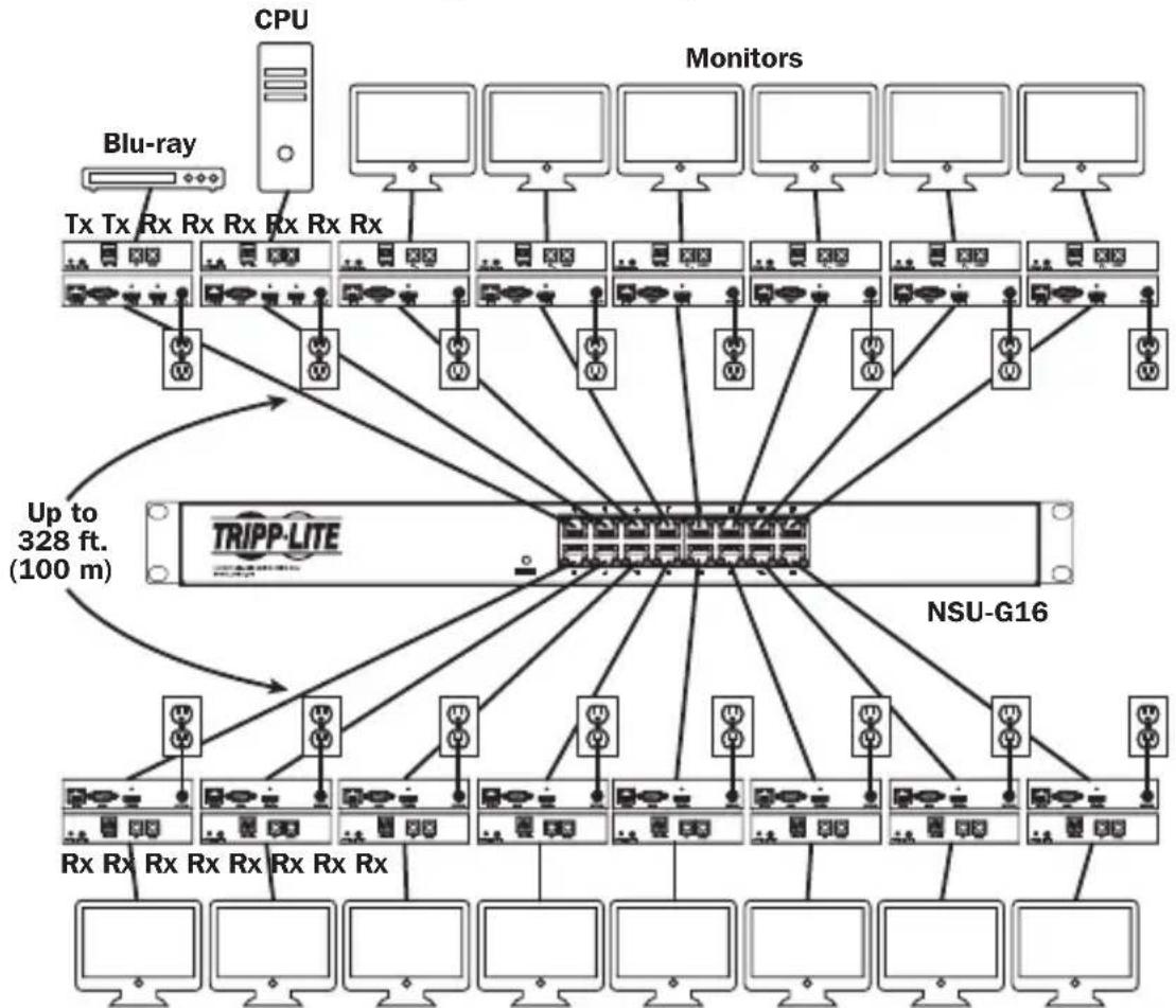
- Transmitters can be located up to 328 ft. (100 m) from the switch, with an additional 328 ft. (100 m) between the switch and the receiver, for a total distance of 656 ft. (200 m).
- Can also be used in a point-to-point installation where the transmitter directly connects to a receiver up to 328 ft. (100 m) away.
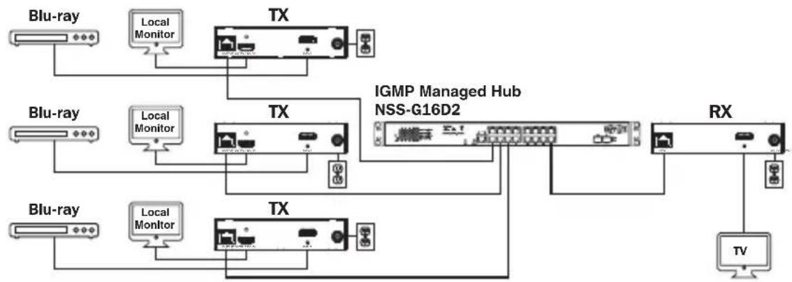
- Designed for managed network switches with IGMP, which allow login and remote management via the switch interface.
- Video source can be sent to any analog or digital display (e.g. Component Video to HDMI, VGA to HDMI, HDMI to DisplayPort, HDMI to HDMI).
- Display a single source on a single monitor or distribute a single signal to multiple monitors.
- B160-200-HSI and B160-201-HSI receiver units include two HDMI output ports for connection of two monitors.
- Connect up to 64 transmitters and 255 receivers in a single managed switch installation.
- Utilizes H.264 video compression standard.
- Extends IR control signals that control a source (such as a Blu-ray™ player) from a remote display.
Uses a 20kHz to 60kHz IR frequency.
Supports RS-232 Serial baud rates up to 57600 bps. - VGA video models support video resolutions up to 1920 x 1440, including 1080p.
- DisplayPort and HDMI models support video resolutions up to 1920 x 1080 (1080p).
Product Features
- Component video models support video resolutions up to 1080i.
Each transmitter features an HDMI output port for connecting a local monitor. - HDCP and 3D compatible.
- Includes mounting hardware for wall-mount, rack mount or pole mount installations.
- Plug and play; no software or drivers required.
**Connect a DVI source and/or monitor using an HDMI to DVI adapter (select models include an HDMI to DVI adapter). HDMI to DVI adapter cables (Tripp Lite P566-Series) are available, sold separately.
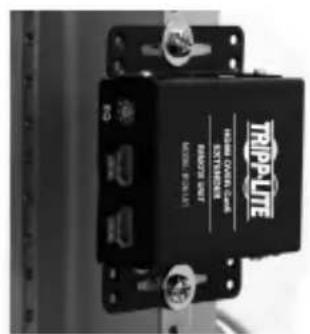
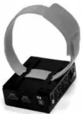
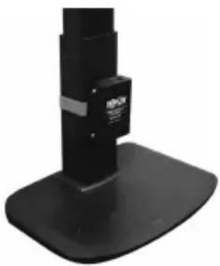
Mounting Instructions
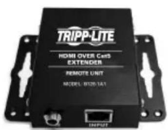
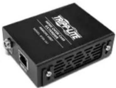
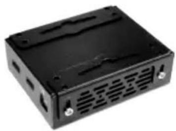
Audio/Video over IP extenders include mounting hardware that allows for a variety of mounting options. The following images demonstrate these mounting methods.
Note: Model B126-1A1 is shown for illustrative purposes; installation for Audio/Video over IP extender units is the same.

Wall-mount


19" Rack-mount

Pole-mount
Point-to-Point Installation
Notes:
- Test to ensure the entire installation works properly before pulling cables through ceilings/walls.
- To achieve maximum distance and performance, use 24 AWG solid wire Cat5e/6 cable. Using stranded wire cable or cable with a gauge (AWG) size higher than recommended will result in a shorter extension distance. Higher gauge cabling (such as 26 AWG) has a limited transmission capability compared to lower-gauge cabling. All Tripp Lite N202-Series Cat6 cables use 24 AWG solid wire cabling. Extended lengths of 23 AWG solid wire Cat6a cable are available from Tripp Lite as a custom order.
-
Transmitter and receiver kits are available in DisplayPort, HDMI and VGA, but separate transmitters and receivers can be purchased in any combination (e.g. Component Video to HDMI, VGA to HDMI, HDMI to VGA, HDMI to DisplayPort).
-
Ensure all equipment to be connected is powered off.
- Connect the audio/video source to the transmitter unit's input port (see Optional Accessories for available Tripp Lite audio/video cables).
- (Optional) Connect the computer's DB9 port to the transmitter unit's serial port. Depending on the model, the serial port will be either DB9 or 3.5mm . Models with 3.5mm jacks include a 3.5mm to DB9 adapter. Models with DB9 ports require standard RS-232 DB9 cable (sold separately) for connecting to a computer.
- (Optional) Connect the included IR-OUT cable to the transmitter unit's IR-OUT port. Place the sensor on the IR-OUT cable in an unobstructed area within clear view of the device being controlled.
Note: The IR-OUT cable receives the signal from the remote control and sends it to the device being controlled (e.g. Blu-ray player, etc.).
- (Optional) Using an HDMI cable, connect a local monitor to the transmitter unit's HDMI output port (see Optional Accessories for available Tripp Lite HDMI cables).
- Connect the external power supply to the local transmitter unit and plug it into a Tripp Lite Surge Protector, Uninterruptible Power Supply (UPS) or Power Distribution Unit (PDU).
Point-to-Point Installation
- Press the Up / Down buttons to set the Channel Number (0-63) on the front of the transmitter unit to a number that will also be used on the receiver unit.
Note: A locking mechanism prevents the Channel Number from being unintentionally changed. When the Channel Number is locked, hold down the Up and Down buttons until the Channel Number starts blinking. Then navigate to the desired Channel using the Up / Down buttons. Once the desired Channel Number has been selected, lock the Channel Number by holding down the Up and Down buttons until the Channel Number stops blinking.
- Using Cat5e/6 cable, connect the transmitter unit's RJ45 Output port to the receiver unit's RJ45 Input port.
Note: The maximum allowable cable length from transmitter to receiver is 328 ft. (100 m).
-
Connect a monitor to the receiver unit's audio/video Output port (See Optional Accessories for available Tripp Lite audio/video cables).
-
(Optional) Connect the serial device's DB9 port to the receiver unit's serial port. Depending on the model, the serial port will be either DB9 or 3.5mm . Models with 3.5mm jacks include a 3.5mm to DB9 adapter. Models with DB9 ports require standard RS-232 DB9 cable (sold separately) for connecting a device.
-
(Optional) Connect the included IR-IN cable to the receiver unit's IR-IN port. Place the sensor on the IR-IN cable in an unobstructed area within clear view of the device being controlled.
Note: The IR-IN cable accepts a signal from a remote control and sends it to a device being controlled on the other end of the installation.
- Connect the external power supply to the receiver unit and plug it into a Tripp Lite Surge Protector, Uninterruptible Power Supply (UPS) or Power Distribution Unit (PDU).
Point-to-Point Installation
- Press the Up / Down buttons to set the Channel Number (0-63) on the front of the receiver unit to a number also used on the transmitter unit.
Note: A locking mechanism prevents the Channel Number from being unintentionally changed. When the Channel Number is locked, hold down the Up and Down buttons until the Channel Number starts blinking. Then navigate to the desired Channel using the Up / Down buttons. Once the desired Channel Number has been selected, lock the Channel Number by holding down the Up and Down buttons until the Channel Number stops blinking.
- Power on all connected devices.
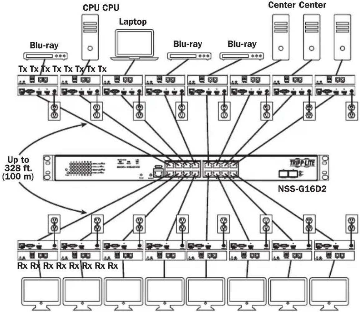
Point-to-Multipoint Installation - Managed Switch with IGMP
Notes:
- Test to ensure the entire installation works properly before pulling cables through ceilings/walls.
- To achieve maximum distance and performance, use 24 AWG solid wire Cat5e/6 cable. Using stranded wire cable or cable with a gauge (AWG) size higher than recommended will result in a shorter extension distance. Higher gauge cabling (such as 26 AWG) has a limited transmission capability compared to lower-gauge cabling. All Tripp Lite N202-Series Cat6 cables use 24 AWG solid wire cabling. Extended lengths of 23 AWG solid wire Cat6a cable are available from Tripp Lite as a custom order.
- B160-Series Audio/Video over IP Extenders are designed for use with a dedicated network switch. Connecting IP Extenders to a switch used with other networking equipment will result in degraded or non-functional product performance.
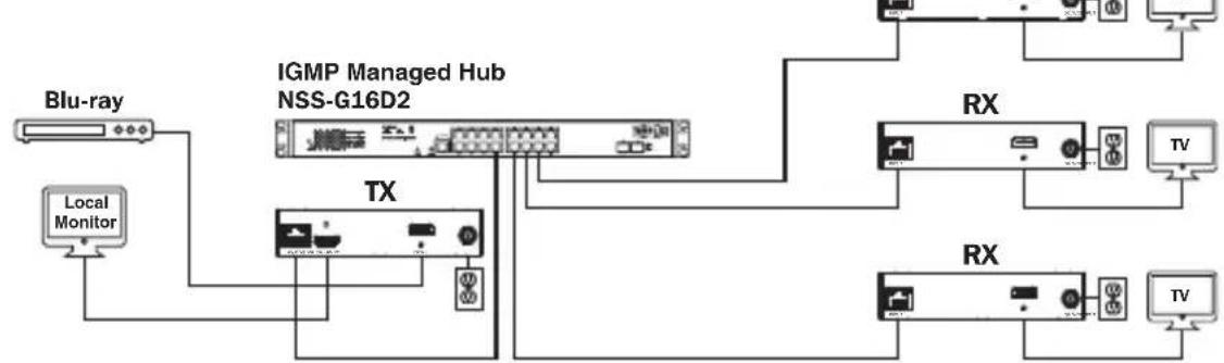
- The installation diagram on the next page shows HDMI transmitters and receivers only, though any combination of transmitters and receivers (e.g. Component Video, DisplayPort, HDMI, VGA) may be used. Up to 64 transmitters and 255 receivers can be connected in a single managed switch installation (the diagram shown stops at a single 16-port network switch).
- The installation diagram on the next page shows only required connections. Optional connections (such as the IR-IN and IR-OUT Cables) are not shown.
Point-to-Multipoint Installation - Managed Switch with IGMP
Installation Overview (All Models)
Point-to-Multipoint Installation - Managed Switch with IGMP
B160-103-HDSI Kit
B160-301-HDSI Kit
B160-202-HDSI Kit
Point-to-Multipoint Installation - Managed Switch with IGMP
- Ensure all equipment to be connected is powered off.
- Connect the audio/video source to the transmitter unit's input port (see Optional Accessories for available Tripp Lite audio/video cables).
- (Optional) Connect the computer's DB9 port to the transmitter unit's serial port. Depending on the model, the serial port will be either DB9 or 3.5mm . Models with 3.5mm jacks include a 3.5mm to DB9 adapter. Models with DB9 ports require standard RS-232 DB9 cable (sold separately) for connecting to a computer.
- (Optional) Connect the included IR-OUT cable to the transmitter unit's IR-OUT port. Place the sensor and cable in an unobstructed area within clear view of the device being controlled.
Note: The IR-OUT cable receives the signal from the remote control and sends it to the device being controlled (e.g. Blu-ray player, etc.).
- (Optional) Using an HDMI cable, connect a local monitor to the transmitter unit's HDMI output port (see Optional Accessories for available Tripp Lite HDMI cables).
- Set the Channel Number (0 to 63 are available) on the front of the transmitter to a desired number by pressing the Up / Down buttons. This number MUST be the same on all transmitter and receiver units in the installation. If you are using transmitter and receiver units that are all brand new, they will default to Channel Number 0 and you can leave the channel unchanged upon installation.
Note: A locking mechanism prevents the Channel Number from being unintentionally changed. When the Channel Number is locked, hold down the Up and Down buttons until the Channel Number starts blinking. Then navigate to the desired Channel using the Up / Down buttons. Once the desired Channel Number has been selected, lock the Channel Number by holding down the Up and Down buttons until the Channel Number stops blinking.
- Connect the RJ45 Output port on the transmitter unit to an RJ45 port on the network switch using Cat5e/6 cable.
Note: The maximum allowable cable length from transmitter to switch is 328 ft. (100 m).
Point-to-Multipoint Installation - Managed Switch with IGMP
Do not connect the external power supply to the transmitter at this time. The transmitter should not be powered on until all audio/video equipment is connected and powered on.
- To connect additional transmitter(s), repeat steps 2 through 7.
- Connect a monitor to the receiver unit's audio/video Output port (See Optional Accessories for available Tripp Lite audio/video cables).
- (Optional) Connect the serial device's DB9 port to the receiver unit's serial port. Depending on the model, the serial port will be either DB9 or 3.5mm . Models with 3.5mm jacks include a 3.5mm to DB9 adapter. Models with DB9 ports require standard RS-232 DB9 cable (sold separately) for connecting a device.
- (Optional) Connect the included IR-IN cable to the receiver unit's IR-IN port. Place the sensor on the IR-IN cable in an unobstructed area within clear view of the remote control.
Note: The IR-IN cable accepts a signal from a remote control and sends it to a device being controlled on the other end of the installation.
- Set the Channel Number (0 to 63 are available) on the front of the receiver to a desired number by pressing the Up / Down buttons. This number MUST be the same on all transmitter and receiver units in the installation. If you are using transmitter and receiver units that are all brand new, they will default to channel number 0, and you can leave the channel unchanged upon installation.
Note: A locking mechanism prevents the Channel Number from being unintentionally changed. When the Channel Number is locked, hold down the Up and Down buttons until the Channel Number starts blinking. Then navigate to the desired Channel using the Up / Down buttons. Once the desired Channel Number has been selected, lock the Channel Number by holding down the Up and Down buttons until the Channel Number stops blinking.
- Connect the RJ45 Input port on the receiver unit to an RJ45 port on the network switch using Cat5e/6 cable.
Note: The maximum allowable cable length from receiver to switch is 328 ft. (100 m).
Point-to-Multipoint Installation - Managed Switch with IGMP
Do not connect the external power supply to the receiver at this time. The receiver should not be powered on until all audio/video equipment is connected and powered on.
- To connect additional receivers, repeat steps 9 through 13.
- Power on all connected devices.
- Connect the external power supplies to all transmitter and receiver units in the installation, then plug the external power supplies into Tripp Lite Surge Protectors, Uninterruptible Power Supplies (UPS) or Power Distribution Units (PDU).
Operation of Point-to-Multipoint Installation - Managed Switch with IGMP
Notes:
- B160-Series Audio/Video over IP Extenders are designed for use with a dedicated network switch. Connecting IP Extenders to a switch used with other networking equipment will result in degraded or non-functional product performance.
-
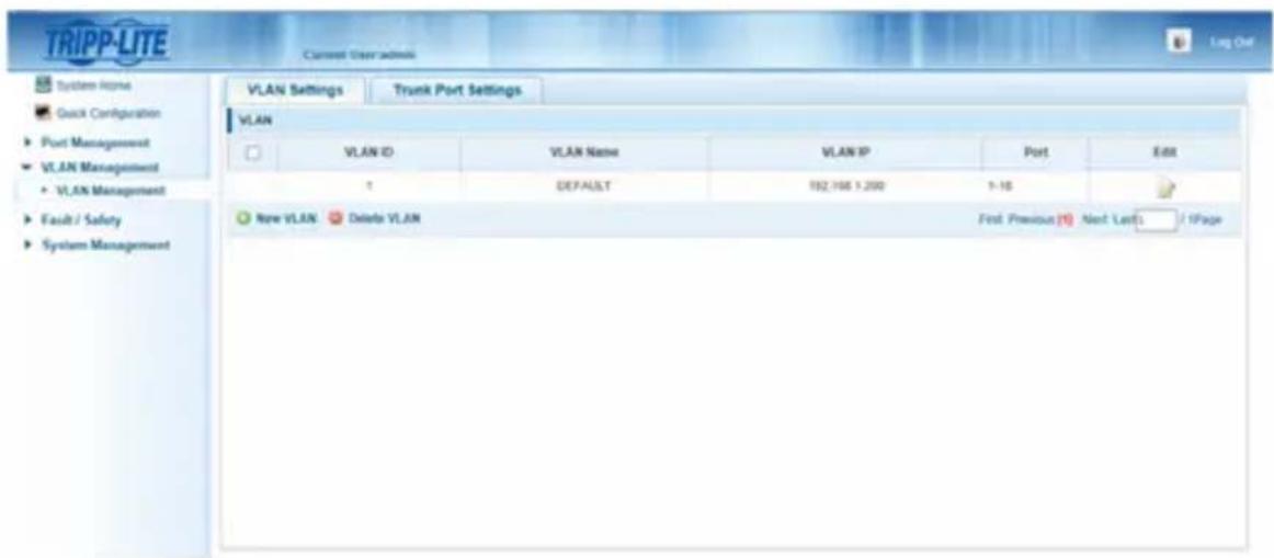
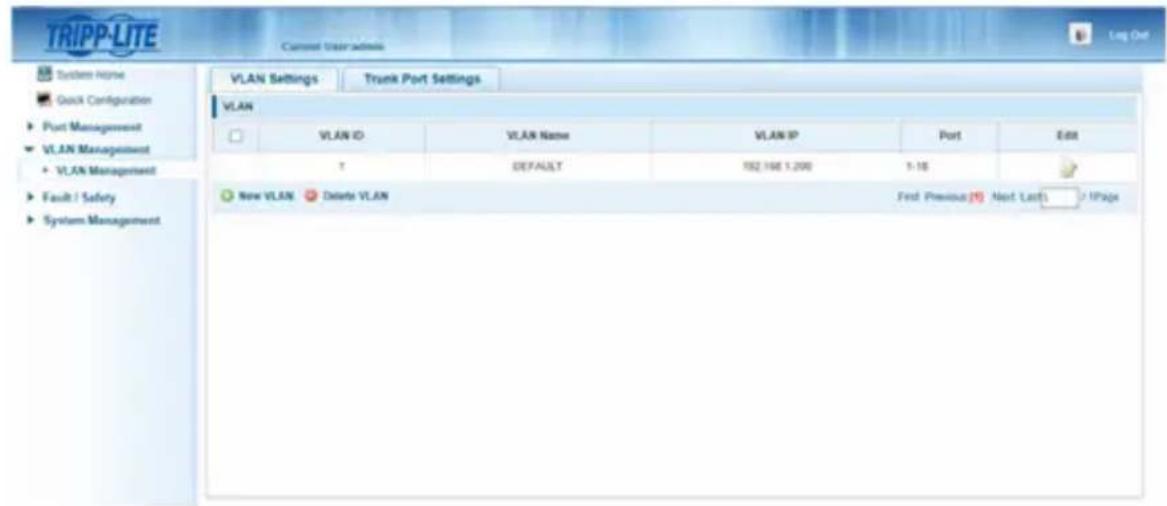
The model screenshots shown in the steps below are a Tripp Lite NSS-G16D2 Network Switch. Operation of different switches will vary by model.
-
Log into the network switch user interface.
- Navigate to the VLAN Management section.
Operation of Point-to-Multipoint Installation - Managed Switch with IGMP
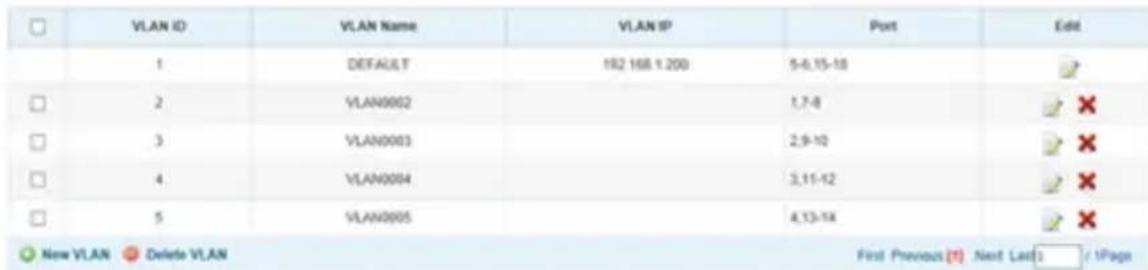
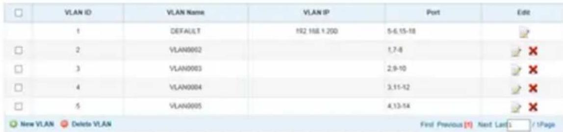
- In the VLAN Management section, create a new VLAN for each transmitter in the installation. The transmitter port number should always be the first number in the VLAN, followed by the port numbers (separated by commas) of all receiver units that will be transmitting audio/video to and from the selected transmitter. The screenshot below shows VLAN's for four transmitters (VLAN0002 through VLAN0005). VLAN0002 represents the transmitter connected to port 1, the audio/video of which is transmitted to the receivers connected to ports 7 and 8. Similarly, VLAN0003 represents the transmitter connected to port 2, whose audio/video is transmitted to receivers connected to ports 9 and 10.
-
To switch the source of the audio/video on a receiver, go to and edit the VLAN of the associated transmitters to add/remove the desired ports.
-
As more transmitters and receivers get added to the installation, simply add additional VLANs for the new transmitters and add the new receivers to the VLANs of the desired transmitters.
Point-to-Multipoint Installation - Unmanaged Switch
Notes:
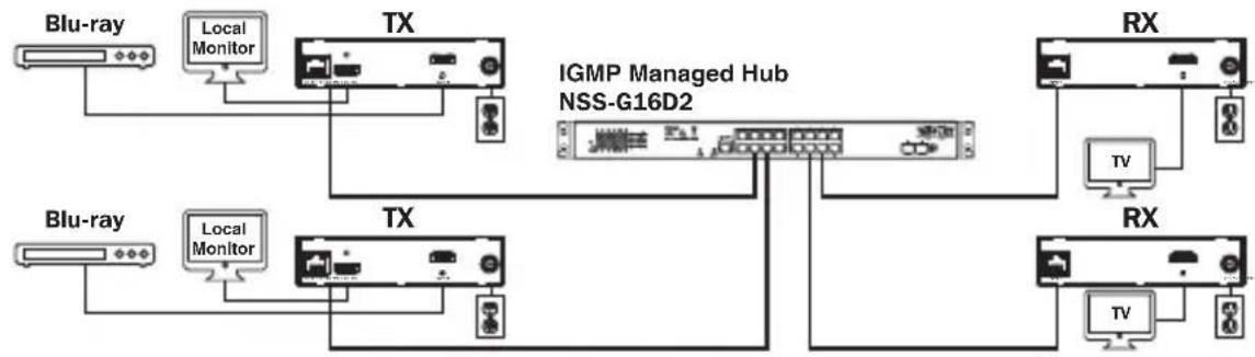
- Unmanaged switch installations are limited to two transmitter units. The number of receiver units is limited to the number of ports remaining on the unmanaged switch.
- Test to ensure the entire installation works properly before pulling cables through ceilings/walls.
- To achieve maximum distance and performance, use 24 AWG solid-wire Cat5e/6 cable. Using stranded-wire cable or cable with a gauge (AWG) size higher than recommended will result in a shorter extension distance. Higher-gauge cabling (such as 26 AWG) has a limited transmission capability compared to lower-gauge cabling. All Tripp Lite N202-Series Cat6 cables use 24 AWG solid-wire cabling. Extended lengths of 23 AWG solid-wire Cat6a cable are available from Tripp Lite as a custom order.
- B160-Series Audio/Video over IP Extenders are designed for use with a dedicated network switch. Connecting IP Extenders to a switch used with other networking equipment will result in degraded or non-functional product performance.
- The installation diagram on the next page shows HDMI transmitters and receivers only, though any combination of transmitters and receivers (e.g. Component Video, DisplayPort, HDMI, VGA) may be used.
- The installation diagram on the next page shows only required connections. Optional connections (such as the IR-IN and IR-OUT Cables) are not shown.
Point-to-Multipoint Installation – Unmanaged Switch
Installation Overview (All Models)
- Ensure all equipment to be connected is powered off.
- Connect the audio/video source to the transmitter unit's input port (see Optional Accessories for available Tripp Lite audio/video cables).
- (Optional) Connect the computer's DB9 port to the transmitter unit's serial port. Depending on the model, the serial port will be either DB9 or 3.5mm . Models with 3.5mm jacks include a 3.5mm to DB9 adapter. Models with DB9 ports require standard RS-232 DB9 cable (sold separately) for connecting to a computer.
Point-to-Multipoint Installation - Unmanaged Switch
- (Optional) Connect the included IR-OUT cable to the transmitter unit's IR-OUT port. Place the sensor on the IR-OUT cable in an unobstructed area within clear view of the device being controlled.
Note: The IR-OUT cable receives the signal from the remote control and sends it to the device being controlled (e.g. Blu-ray player, etc.).
- (Optional) Using an HDMI cable, connect a local monitor to the transmitter unit's HDMI output port (see Optional Accessories for available Tripp Lite HDMI cables).
- Set the Channel Number (0 to 63 are available) on the front of the transmitter to a desired number by pressing the Up / Down buttons. The channel number of all transmitters in the installation MUST be different.
Note: A locking mechanism prevents the Channel Number from being unintentionally changed. When the Channel Number is locked, hold down the Up and Down buttons until the Channel Number starts blinking. Then navigate to the desired Channel using the Up / Down buttons. Once the desired Channel Number has been selected, lock the Channel Number by holding down the Up and Down buttons until the Channel Number stops blinking.
- Connect the RJ45 Output port on the transmitter unit to an RJ45 port on the network switch using Cat5e/6 cable.
Note: The maximum allowable cable length from receiver to switch is 328 ft. (100 m).

Do not connect the external power supply to the transmitter at this time. The transmitter should not be powered on until all audio/video equipment is connected and powered on.
- To connect an additional transmitter, repeat steps 2 through 7.
- Connect a monitor to the receiver unit's audio/video Output port (See Optional Accessories for available Tripp Lite audio/video cables).
- (Optional) Connect the serial device's DB9 port to the receiver unit's serial port. Depending on the model, the serial port will be either DB9 or 3.5mm . Models with 3.5mm jacks include a 3.5mm to DB9 adapter. Models with DB9 ports require standard RS-232 DB9 cable (sold separately) for connecting a device.
Point-to-Multipoint Installation - Unmanaged Switch
- (Optional) Connect the included IR-IN cable to the receiver unit's IR-IN port. Place the sensor on the IR-IN cable in an unobstructed area within clear view of the remote control.
Note: The IR-IN cable accepts a signal from a remote control and sends it to a device being controlled on the other end of the installation.
- Set the Channel Number (0 to 63 are available) on the front of the receiver to match the channel number of the transmitter whose audio/video you want to receive by pressing the Up / Down buttons.
Note: A locking mechanism prevents the Channel Number from being unintentionally changed. When the Channel Number is locked, hold down the Up and Down buttons until the Channel Number starts blinking. Then navigate to the desired Channel using the Up / Down buttons. Once the desired Channel Number has been selected, lock the Channel Number by holding down the Up and Down buttons until the Channel Number stops blinking.
- Connect the RJ45 Input port on the receiver unit to an RJ45 port on the network switch using Cat5e/6 cable.
Note: The maximum allowable cable length from receiver to switch is 328 ft. (100 m).

Do not connect the external power supply to the receiver at this time. The receiver should not be powered on until all audio/video equipment is connected and powered on.
- To connect additional receivers, repeat steps 9 through 13.
- Power on all connected devices.
- Connect the external power supplies to all transmitter and receiver units in the installation, then plug the external power supplies into Tripp Lite Surge Protectors, Uninterruptible Power Supplies (UPS) or Power Distribution Units (PDU).
- Once in operation, change the monitor source signal by simply changing the channel of the corresponding receiver to match that of the transmitter with the desired source signal.
Troubleshooting
If unable to receive an acceptable image after following the installation instructions, try the following troubleshooting tips:
- Are the included external power supplies connected and plugged into a working power source? For the product to function properly, it must be connected to and receiving power from the external power supply.
- Was the power to the connected devices turned off prior to installation? If not, restart all connected devices.
- Were the connected audio/video devices powered on before the transmitter and receiver units? If not, disconnect power from all transmitter and receiver units, then power them back on.
- What resolution are you trying to obtain? Make sure the installation is within the maximum distance and resolution specs supported by the model as referenced in the Product Features section of this manual. If unable to obtain an acceptable image, try lowering the computer's video resolution or adjusting the refresh rate.
- What type of cabling is used in the installation? Inferior cabling can result in poor performance. It is important to use cables that support the desired video resolution. To achieve maximum distance and resolution, 24 AWG solid-wire Cat5e/6 cable or 23 AWG solid-wire Cat6a cable must be used. Tripp Lite's N202-Series Cat6 cables use 24 AWG solid wire, as do the N022-01K-GY (Cat5) and N222-01K-GY bulk cables. The audio/video cables used must also support the desired video resolution. Inexpensive, low quality cables may not support the maximum resolution. It is recommended that you use the Tripp Lite cables listed in the Optional Accessories section of this manual.
- Test the cables to ensure they are working properly. For example, connect the audio/video cable between a source and functioning monitor to ensure the cable is not defective. For Cat5e/6 cable, connect it between a computer and a network to verify it establishes a network connection.
Troubleshooting
- Check cabling for any damages that may have occurred during installation. If a cable connector is loosened from pulling through ceilings/wall or the cable jacket is damaged with the wiring exposed, maximum performance will not be achieved.
- Are the transmitter(s) and/or receiver(s) located in an area with exposure to higher temperatures? If the product is overheated, it will not function properly.
- Do not set identical channel numbers for transmitters in an Unmanaged Switch installation. Doing so will result in no signal being displayed on monitors connected to receivers assigned to the same channel number. If this happens, change the transmitters' channel numbers to unique numbers and assign the desired channel number to the affected receivers. If audio/video does not reappear after doing this, disconnect power from the affected transmitter and receiver units, wait 10 seconds, and reconnect the power.
- Do not connect more than two transmitters in an unmanaged switch installation. Unmanaged switch installations are limited to two transmitters, with the number of receivers being limited to the number of ports remaining on the unmanaged switch.
- Do not connect other networking equipment to the network switch. The B160-Series Audio/Video over IP Extenders are designed for use with a dedicated network switch. Connecting them to a switch used with other networking equipment will result in degraded or non-functional product performance.
Warranty and Product Registration
1-Year Warranty
Tripp Lite warrants its products to be free from defects in materials and workmanship for a period of one (1) year from the date of initial purchase. Tripp Lite's obligation under this warranty is limited to repairing or replacing (at its sole option) any such defective products. To obtain service under this warranty, you must obtain a Returned Material Authorization (RMA) number from Tripp Lite or an authorized Tripp Lite service center. Products must be returned to Tripp Lite or an authorized Tripp Lite service center with transportation charges prepaid and must be accompanied by a brief description of the problem encountered and proof of date and place of purchase. This warranty does not apply to equipment, which has been damaged by accident, negligence or misapplication or has been altered or modified in any way.
EXCEPT AS PROVIDED HEREIN, Tripp Lite MAKES NO WARRANTYES, EXPRESS OR IMPLIED, INCLUDING WARRANTYES OF MERCHANTABILITY AND FITNESS FOR A PARTICULAR PURPOSE. Some states do not permit limitation or exclusion of implied warranties; therefore, the aforesaid limitation(s) or exclusion(s) may not apply to the purchaser.
EXCEPT AS PROVIDED ABOVE, IN NO EVENT WILL Tripp Lite BE LIABLE FOR DIRECT, INDIRECT, SPECIAL, INCIDENTAL OR CONSEQUENTIAL DAMAGES ARISING OUT OF THE USE OF THIS PRODUCT, EVEN IF ADVISED OF THE POSSIBILITY OF SUCH DAMAGE. Specifically, Tripp Lite is not liable for any costs, such as lost profits or revenue, loss of equipment, loss of use of equipment, loss of software, loss of data, costs of substitutes, claims by third parties, or otherwise.
PRODUCT REGISTRATION
Visit www.triplite.com/warranty today to register your new Tripp Lite product. You'll be automatically entered into a drawing for a chance to win a FREE Tripp Lite product!*
- No purchase necessary. Void where prohibited. Some restrictions apply. See website for details.
FCC Notice, Class B
This device complies with part 15 of the FCC Rules. Operation is subject to the following two conditions: (1) This device may not cause harmful interference, and (2) this device must accept any interference received, including interference that may cause undesired operation.
Note: This equipment has been tested and found to comply with the limits for a Class B digital device, pursuant to part 15 of the FCC Rules. These limits are designed to provide reasonable protection against harmful interference in a residential installation. This equipment generates, uses and can radiate radio frequency energy and, if not installed and used in accordance with the instructions, may cause harmful interference to radio communications. However, there is no guarantee that interference will not occur in a particular installation. If this equipment does cause harmful interference to radio or television reception, which can be determined by turning the equipment off and on, the user is encouraged to try to correct the interference by one or more of the following measures:
- Reorient or relocate the receiving antenna.
- Increase the separation between the equipment and receiver.
- Connect the equipment into an outlet on a circuit different from that to which the receiver is connected.
- Consult the dealer or an experienced radio/TV technician for help.
Any changes or modifications to this equipment not expressly approved by Tripp Lite could void the user's authority to operate this equipment.
Tripp Lite has a policy of continuous improvement. Specifications are subject to change without notice. Photos and illustrations may differ slightly from actual products.


1111 W. 35th Street, Chicago, IL 60609 USA • www.triplite.com/support
Copyright © 2019 Tripp Lite.
Note: El cable IR-IN accepts a new signal to the control remoto and the envia a new dispositivo that can be used for the installation of the installation.
1111 W. 35th Street, Chicago, IL 60609 USA • www.triplite.com/support
1111 W. 35th Street, Chicago, IL 60609 USA • www.triplite.com/support
PykoBODCTBO N0Ib30BaTeJia
PetpancIaTOpbl aydno-/BndeocnHaIa c pa3bemom RS-232 n IK-ynpaBleHneM no npotoKoIy IP
Modell petpansTopoB B
KOMnneKeTe:
B160-101-DPSI
B160-101-DPHDSI
B160-101-HDSI
B160-103-HDSI
B160-201-HSI
B160-202-HDSI
B160-301-HDSI
Moden
NepedaTcuKOB:
B160-001-CSI B160-001-DPSI
B160-001-HDSI B160-001-VSI
Moden
PnEmHKnOB:
B160-100-CSI B160-100-DPSI
B160-100-HDSI
B160-100-VSI B160-200-HSI
English 1 • Espanol 25 • Français 50

TRIPP·LITE

PpOPOPMN MIOHIOO HONHO
1111 W. 35th Street, Chicago, IL 60609 USA • www.triplite.com/support
OxpaHareTcraBTopCKnM npaBOM © 2019 Tripp Lite.
Bce ToproBbIe 3HaKn ABnHOTc NCKNIOHTeBHO Co6CTBEHHOCTbO CBONX COOTBeTCTBYUINX BlaJeBueB.
CopejxHmoe ynaKOBKn
| PtepeDarutyuk (T), Ptpemekhuk (R), Kowmnekrt (R) | |||||||||
| Bheelunni Gnok nmtatnau | |||||||||
| Bxodhoi MK-ka6genb | |||||||||
| Bxodhoi MK-ka6genb | |||||||||
| Bxodhoi MK-ka6genb | |||||||||
| Bxodhoi MK-ka6genb | |||||||||
| Bxodhoi MK-ka6genb | 1111111112224244 | B160-001-CSI | |||||||
| 1111111112224244 | B160-001-DPSI | ||||||||
| 11111111123 | B160-001-HDSI | ||||||||
| 11111111123 | B160-001-VSI | ||||||||
| 11111111123 | B160-100-CSI | ||||||||
| 11111111123 | B160-100-DPSI | ||||||||
| 11111111123 | B160-100-HDSI | ||||||||
| 11111111123 | B160-100-VSI | ||||||||
| 11111111123 | B160-200-HSI | ||||||||
| 11111111123 | B160-101-DPSI | ||||||||
| 11111111123 | B160-101-DPHDSI | ||||||||
| 11111111123 | B160-101-HDSI | ||||||||
| 11111111123 | B160-103-HDSI | ||||||||
| 11111111123 | B160-201-HSI | ||||||||
| 11111111123 | B160-202-HDSI | ||||||||
| 11111111123 | B160-301-HDSI | ||||||||
| Mothrakhthe pnpictoc6ghnuc | |||||||||
| Ka66gen-bnepeoxoHnikc | |||||||||
| Ka66gen-bnepeoxoHnikc | |||||||||
| Ka66gen-bnepeoxoHnikc | |||||||||
| Ka66gen-bnepeoxoHnikc | |||||||||
| Ka66gen-bnepeoxoHnikc | 00001011101123 | ||||||||
| Ka66gen-bnepeoxoHnikc | 00001011101123 | ||||||||
| Ka66gen-bnepeoxoHnikc | 00001011101123 | ||||||||
| Ka66gen-bnepeoxoHnikc | 0000001000124044 | ||||||||
| Ka66gen-bnepeoxoHnikc | 0000001000124044 | ||||||||
| Ka66gen-bnepeoxoHnikc | 0000001000124044 | ||||||||
| Ka66gen-bnepeoxoHnikC | 0000001000124044 | ||||||||
| Ka66gen-bnepeoxoHnikC | 0000001000124044 | ||||||||
| Ka66gen-bnepeoxoHnikC | 0000001000124045 | ||||||||
| Ka66gen-bnepeoxoHnikC | 0000001000124045 | ||||||||
| Ka66gen-bnepeoxoHnikC | 0000001000124045 | ||||||||
| Ka66gen-bnepeoxoHnikc | 0000001000124045 | ||||||||
| Ka66gen-bnepeoxoHnikc | 0000001000124045 | ||||||||
| Ka66gen-bnepeoxoHnikc | 0000001000124044 | ||||||||
| Ka66gen-bnepeoxoHnikc | 0000001000124044 | ||||||||
| Ka66gen-bnepeoxoHnikf | 0000001000124044 | ||||||||
| Ka66gen-bnepeoxoHnikf | 0000001000124044 | ||||||||
| Ka66gen-bnepeoxoHnikf | 0000001000124045 | ||||||||
| Ka66gen-bnepeoxoHnikf | 0000001000124045 | ||||||||
| Ka66gen-bnepeoxoHnikf | 0000001000124045 | ||||||||
| Ka66gen-bnepeoxoHnikg | 0000001000124045 | ||||||||
| Ka66gen-bnepeoxoHnikg | 0000001000124045 | ||||||||
| Ka66gen-bnepeoxoHnikg | 0000001000124044 | ||||||||
| Ka66gen-bnepeoxoHnikg | 0000001000124044 | ||||||||
| Ka66gen-bnepeoxoHnikg | 0000001000124044 | ||||||||
| Ka66gen-bnepeoxoHnikf | 0000001000124045 | ||||||||
| Ka66gen-bnepeoxoHnikf | 0000001000124044 | ||||||||
| Ka66gen-bnepeoxoHnikf | 0000001000124045 | ||||||||
| Ka66gen-bnepeoxoHnikg | 0000001000124045 | ||||||||
| Ka66gen-bnepeoxoHnikf | 0000001000124045 | ||||||||
| Ka66gen-bnepeoxoHnikg | 0000001000124044 | ||||||||
| Ka66gen-bnepeoxoHnikg | 0000001000124045 | ||||||||
| Ka66gen-bnepeoxoHnikg | 0000001000124045 | ||||||||
| Ka66gen-bnepeoxoHnikf | 0000001000124044 | ||||||||
| Ka66gen-bnepeoxoHnikf | 0000001000124044 | ||||||||
| Ka66gen-bnepeoxoHnikg | 0000001000124045 | ||||||||
| Ka66gen-bnepeoxoHnikg | 0000001000124044 | ||||||||
| Ka66gen-bnepeoxoHnikf | 0000001000124044 | ||||||||
| Ka66gen-bnepeoxoHnikg | 0000001000124044 | ||||||||
| Ka66gen-bnepeoxoHnikg | 0000001000124045 | ||||||||
| Ka66gen-bnepeoxoHnikf | 0000001000124044 | ||||||||
| Ka66gen-bnepeoxoHnikg | 0000001000124045 | ||||||||
| Ka66gen-bnepeoxoHnikf | 0000001000124045 | ||||||||
| Ka66gen-bnepeoxoHnikf | 0000001000124044 | ||||||||
| Ka66gen-bnepeoxoHnikg | 0000001000124044 | ||||||||
| Ka66gen-bnepeoxoHnikf | 0000001000124044 | ||||||||
| Ka66gen-bnepeoxoHnikf | 0000001000124048 | ||||||||
| Ka66gen-bnepeoxoHnikg | 0000001000124048 | ||||||||
| Ka66gen-bnepeoxoHnikg | 0000001000124048 | ||||||||
| Ka66gen-bnepeoxoHnikf | 0000001000124048 | ||||||||
| Ka66gen-bnepeoxoHnikg | 0000001000124048 | ||||||||
| Ka66gen-bnepeoxoHnikf | 0000001000124044 | ||||||||
| Ka66gen-bnepeoxoHnikg | 0000001000124044 | ||||||||
| Ka66gen-bnepeoxoHnik f | 0000001000124044 | ||||||||
| Ka66gen-bnepeoxoHnikf | 0000001000124044 | ||||||||
| Ka66gen-bnepeoxoHnikf | 0000001000124049 | ||||||||
| Ka66gen-bnepeoxoHnikf | 0000001000124049 | ||||||||
| Ka66gen-bnepeoxoHnikf | 0000001000124049 | ||||||||
| Ka66gen-bnepeoxoHnik f | 0000001000124049 | ||||||||
| Ka66gen-bnepeoxoHnikf | 0000001000124049 | ||||||||
| Ka66gen-bnepeoxoHnikf | 0000001000124048 | ||||||||
| Ka66gen-bnepeoxoHnikf | 0000001000124048 | ||||||||
| Ka66gen-bnepeoxoHnikf | 0000001000124048 | ||||||||
| Ka66gen-bnepeoxoHnik f | 0000001000124048 | ||||||||
| Ka66gen-bnepeoxoHnikf | 0000001000124048 | ||||||||
| Ka66gen-bnepeoxoHnikf | 0000001000124049 | ||||||||
| Ka66gen-bnepeoxoHnikf | 0000001000124049 | ||||||||
| Ka66gen-bnepeoxoHnikg | 0000001000124049 | ||||||||
| Ka66gen-bnepeoxoHnikg | 0000001000124049 | ||||||||
| Ka66gen-bnepeoxoHnikg | 0000001000124048 | ||||||||
| Ka66gen-bnepeoxoHnikg | 0000001000124048 | ||||||||
| Ka66gen-bnepeoxoHnikg | 0000001000124049 | ||||||||
| Ka66gen-bnepeoxoHnikg | 0000001000124049 | ||||||||
| Ka66gen-bnepeoxoHnikf | 0000001000124049 | ||||||||
| Ka66gen-bnepeoxoHnikf | 0000001000124044 | ||||||||
| Ka66gen-bnepeoxoHnikf | 0000001000124044 | ||||||||
| Ka66gen-bnepeoxoHnik f | 0000001000124049 | ||||||||
| Ka66gen-bnepeoxoHnikf | 0000001000124049 | ||||||||
| Ka66gen-bnepeoxoHnikg | 0000001000124048 | ||||||||
| Ka66gen-bnepeoxoHnikg | 0000001000124049 | ||||||||
| Ka66gen-bnepeoxoHnikf | 0000001000124049 | ||||||||
| Ka66gen-bnepeoxoHnikg | 0000001000124044 | ||||||||
| Ka66gen-bnepeoxoHnikf | 0000001000124044 | ||||||||
| Ka66gen-bnepeoxoHnik g | 0000001000124049 | ||||||||
| Ka66gen-bnepeoxoHnikg | 0000001000124049 | ||||||||
OngnohaIbHbIe KOMnIeKtYuOuIe
CoeHHTbHbI Ka6eB NpeDaun KOMnoHrTO BuaOcHHa a Cn03oNoeHHbIMN BbIBoMaM A008-006, dHa 1,8 M
- CoeHnTeBhIe Ka6eN Cat6 cepu N202 cOndoxKnbHbIM npoBoaMn Ka16pa 24 AWG
- 16-nopToBbIynpaBnEmbIcTeBoiKoMMyTaTOpGigabitL2MoJ.NSS-G16D2c8-p03eToHbIM PDU
- 24-nopTobB ynpabnemb ceTeBOKOMMyTaTop Gigabit L2 MoI. NSS-G24D2 c 12-po3eToHbIM PDU
VGA-ka6eenn cepnn P502 c koakcnabhbimpa3beMaMn RGB
- ydnnHntbHbI Ka6eB P520-006 cnoceIOBaTeHbIMn pa3beMaMn RS-232, dHa 1,8 M
- OdnokhaHalbHeIe Ka6eIIN DVI-D cepnn P561
Ka6eHn-epexoHnKc cepnn P566 c pa3bemamn HDMi n DVI
- BbICOKoCKOpocThbIe HDMI-Ka6eJIncepn P568
- BbICOKoCKOpocThbIe HDMI-ka6eIIN P569-XXX-LOCK* cpa3beMaMn Ethernet n FmKcnpuoummn BnHTaMn
- Ka6eni DisplayPort™ cepnu P580
- Ka6eIi cepnn P583 c pa3bemamn Mini DisplayPort n DisplayPort
*XXX COOTBETCTBYET DnHHe. BbInyckaemblie Ka6eHN HMeIOT DnHHy 1,8 M (006), 3 M (010) u 4,5 M (015).
XapakTepeNCTnKn npOdyKta
- 06ecneuBaetpeTpaHcIaIIO npacnpedeJIeHne ayduo-/BnDEocnHaJIOB, a TaKKe CnHaJIOB nCTaHNoHHoro ynpabIeHnC nocJeIOBaTeIbHO nOdkJIIOyaeMbIX n HΦpaKpaChbIX yCTpoiCTB uepe3 ka6eni Cat5/Cat6.
- Bыньсаимье модени ИмeIoT pa3bembl Component Video + Stereo Audio, DisplayPort, HDMI** n VGA + Stereo Audio.
- Ppeo6pa3yET BnDcOcHnA, NocTynaUoIu OT NCTOChNka, B CnHaN, KOTOpB MoKet nepeJaBaTbCra Ha ceTeBOi KOMMyTaTOP u pacnPepdelaTbcyepe3 Hero c NcNoJIb3OBAHnE m npToKoJa IP.
- IpepaTnki Moryt paonolaraTbca Ha pacctoHnn Do 100 M ot KOMMyTaTopa, pacctoHne MeKdy KOMMyTaTopom N npneMHNKOM TaXke MoXe TcoCTabIaTb Do 100 M, YTO o6ecneuBaET cyMMapHoe pacctoHne Do 200 M.
Moryt taKke nCnoB3oBaTbCByCTaHOBkax C dByXToeHuonToNoIornei, rKe nepeDaTuNK noKnIOuaeTcHnOcePdCTBeHHo K npHeMHNky Ha pacctOAHmdo 100 m. - Ппедианчateьдя упаьяembix ceTeBbIX KOMMyTaTOPOB, pa6ToaUxnx no npotoKony IGMP,уTo 06ecneuBAeT Bo3MOxHOCt b BXOda B CnCTeMy I nCtahUHOHHOro ynpabNeHry chepe3 nHTepfeic KOMMyTaTOPa.
- Bindeocurhan ot nctouhka moKeT hAnpaBnTbcra Ha IIO6o aHaIorOBbI uH uΦpOBoI duCnnei (Hanpimep, uee3 ka6eJb c pa3bemamn Component Video-HDMI, VGA-HDMI, HDMI-DisplayPort, HDMI-HDMI).
- 06ecneuBaIOT OTo6paJekHe NcHnla OT OndHOrO nCTouHnka Ha OndHom MOHTope nn paCnpedeJeHne OndHOro CnHaJa MeKdY HeCKoJIbKIMM MOHToPamN.
- Пиемные мodyн B160-200-HSI и B160-201-HSI подва вьхоньх пораз HDMI на подкlioоченя К дByM MOHITOPaM.
- 06ecneuBAOT noKIOUeHne do 64 nepeaTukOB u 255 npnemHKOB BycTaHOBKe cOHNm ynpabJIeMbIM KOMMyTaTOPoM.
- IcnoIb3yeTcTaHdApT CkaTnB uIeocuHaHa H.264.
- PeTpacnlaunIK-cnHAnOB ynpaBHeHnIcToHnKOM (HaNPmep npourpbBaTeJeM Blu-rayTM) ot DnCTaHnOHHOro DnCnneJ.
- IcnoIb3yEmbI cneKtp IK-vaCToT: 20-60 KΓι.
- Пондержka ckоростеи пераши данньх черз полесоватьн вптерфс RS-232 до 57600 6nt/c.
- MoDéni c pa3bēmamn VGA noDæpXnBaIbT BnDeopa3peHnna do 1920 x 1440, BkIouaay 1080p.
XapakTepeNCTnKn npOdyKta
- MoDéNi cpa3bēmAmi DisplayPort n HDMI noДeρЖиBaIr BnDEopa3peSeHnЯdo 1920 x 1080 (1080p).
- MoDéni cpa3bemamn Component Video noDpeXnBaHTo BnuDeopa3peWeHnI do 1080i.
KazdIy pepeaTcHmEeT BbXoHNo nopT HDMI Ira noKnUohnna JokAbhoro MoHHTopa.
CobMeCTHMOCTb C CNTeMaMn HDCP n 3D.
B KOMPJIeK T BKNIOUeHa MOHTaXHnOCHAcTKa IJN KPeIJIeHn K CTeHe, B CTOnKe IIN Ha MaUte. - Повлочене поTekhalorn Plug-and-play 6e3 Heo6xOIMocTи nCnoIb3OBAHЯ KaKOro-ln60 nporpaMMHoroобсчeyняИи дpaIbepOB.
**06ecneuBAOT noKIOUeHHe nCTOHHka DVI-cnHaIa n/nn MoHtopa c nCnoB3oBaHneM nepexodnka HDMi-DVI (NeKOToPbIe moJIeN KOMIIeKTKyIcTpeXoDHNKOM HDMi-DVI). BInyckaemble KOMNaHne Tripp Lite Ka6ennepexoHNk HDMi-DVI (cepN P566) npodaIcTc OTeNbHO.
HnctpyKzno moHTaKy
IP-peTpaHcIaTopb ayDno-/BnDeocnHaNoB KOMPNeKTyOTc MoHTaxHoJ OChAcTKo, o6ecneuBaHOe B03MOxHOCt b KpeJIeHn pa3NHybIM cNoCobAm. 3Tu cNoCobbl KpeJIeHn Ioka3aHbI Ha npEcdTabHeHHbx HIXe UllIOCTpaunx.
PpmeHne. Ha nIIOCTpaunx noka3aHa moenb B126-1A1; yctaHOBka IP-peTpaHCnTOpOB ayno-/BundeocnHaNo OB cyueCTBnEeTc aHaONuHbIM CnOc06m.
HaTeHHbIM MoHTax
MoHTaX B 19-ДIOIMOBOВ CTоИke
YCTaHOBka C DByXToUeHOn TOnOJOrNeI
Примочаня:
- Ipepe npotraBaanem Kaenee chepe3 ctehbl/ntoTkn Heo6xOJMo npOBepuB npaBnIbHOCTb yHKUHNOHPOBaHn BcE yCTaHOBKn.
-ДяdoctnueHmaKcimambHoi nIcTaHmU npOn3BODnteHbOCTn nCnoNb3yIte Ka6enb Cat5e/6 c OHOxINbHbIMn npOBaMn KaIn6pa 0,2 MM². IVcNoJIb3oBaHne Ka6eMa C MHOrOxINbHbIMn npOBaMn INI KabeIc npOBaMn KaIn6pa Bblse MM² npBedeT K cOKpaJeHIO DnHbIpeTpacHcIaIe. Ka6eN6 BoIee BbICOKIX KaIn6pOB (HaPImep, 0,13 MM²) IMeOT orpaHnueHHy IO nepeAioSyIO cNoCoc6HoCTb NO cpABHeHIO C Ka6eMaM6OJIe Hn3Knx KaIn6pbOB. BCE Ka6eN Cat6 cepNI N202 MapKn Tripp Lite n3roTabNaIOCTc C IVcNoJIb3oBAHMe OMHOxINbHbIX npOBaOB KaIn6pa 0,2 MM². IIO INDINuDAyAbHOmy 3aKa3a KOMnaHry Tripp Lite moKeT n3roTabNbBaTb Ka6eN Cat6a yBeJIuYeHHoI dnnHbI c IVcNoJIb3oBAHneM OHOxINbHbIX npOBaOB KaIn6pa 0,26 MM². - Параатчи и пара EMнк, постая мье в komплкт, виусякотс с разьеми DisplayPort, HDIи VGA, HO otдьно pealn3умье параатчи и пара EMнк могут IMetb pa3beMbI B lo6bix coyeTaHnx (hanpimep, Component Video-HDMI, VGA-HDMI, HDMI-DisplayPort, HDMI-HDMI).
1.перд наалом установки Bce полкюецно оборудане дожнб 6ытб obecтоецno.
2. IodKJIouHTE nCTOuHHK ayDnO-/BnDEocnHana K BXoHOMy nopTy nepeJaIOUeRo Moyny (BbIpyckaemble MoJeN y ayno-/BnDEoKa6eNei Tripp Lite nepeuNCHeBb pa3dene OnuHOaHbHbe KomnLekTyoune).
- (Heo6aTeBHO) CoeHHTe nopT DB9 KOMbIOTepa c nocneIOBaTeBHBm npToM nepeDaUoero MoyJIa. B 3abucnMoCTn OT moJIe NocceIOBaTeBHybI npOT MOKeT IMeT b INTEpEeC DB9 nn 3,5 MM. MoJIe C pa3bEmAmN 3,5 MM KOMJIeKTyOTcR nepExOHNKOM 3,5 MM — DB9. IJra IOKnIOueHnK KOMbIOTepy MoJIeN C npTAMN DB9 Tpe6yeTcR cTaHApTHbI Ka6eNb c pa3bEmAmN RS-232 n DB9 (npOdaETc r OTeBHO).
- (Heo6a3aTeNbHO) BCTaBbTe BbIXOHOH IK-Ka6eNB (IR-OUT) n3 KOMnIeKTA B npot IR-OUT nepeaIOUeRO moyJNA. UcTahOBITE DaTuNK Ha Ka6eNB IR-OUT B CBO6OHDOM OT npenrTCTBNI MeCe TaKIM 06pa3OM, YTO6bl ynpabJIeMoe yCTpoiCTBO HaxOuINOCB B npedeJAX npraMoB BuDmOCTN. PpimueHne. Ka6eNB IR-OUT npHHMaET cHnAn DnCTAHUOnHO r npapBHeHn I nepeaET erHa ynpabJIeMoe yCTpoiCTBO (HanpIMep, npouRpbIbATENB Blu-ray n np.).
- (Heo6aTeBho) IoknHHTe loKaHbM MoHtOp K BbIXOHOmy npTy HDMI nepeaioero moyra c noMoUbHDMI-Ka6enr (BbInyckaemble moJeHDMI-Ka6ene Tripp Lite nepeuCnebl B pa3dene OOnnoHaHbHbe KOMnKeKtyouane).
- Поdkлочи Всшнь снок петаши К мecтюшу Мodyю в BKлочи eroВ po3eTKy ceteBOrO ФпьТра, 6noka paCnpdeelenna петаши (PDU) nnn nctouHnka 6ecnepe60Horo
YCTaHOBka C DByXToUeHOn TOnOJOrNei
nntanra (NbPi) Tripp Lite.
- C noMoIbIO KhoIok Up/Down (BBepx/BHn3) Ha nepeInei naHei npepaIoUeTo MoIyIaYCTaHOBHTe HOMep KaHana (0-63), COOTBeTCTByOuIIM TOMy, KOTopbI 6yIeT NcNoIb3oBaTbcA B npHemHom MOdyIe.
PpmeaHne. Jra 3auNTb ot cnyauHoro n3MeHeHn Homepa KaHana npedyCMOTpeh MexaHn3M fKcaun. Pn 3aKcpoBaHOM Homepe KaHana yepxNBaTe KhoNk Up (Bbepx) uDown (BHN3) hxaTbIMu Do Tex nop, noka Homep KaHana He NaHT MraTb. 3aTe mpeiDte Ha JeenaMbI KaHAn C nomoUbIO KhoNOK Up/Down (Bbepx/Bn3). Iocne Bby6opa JKeNaemOro Homepa KaHana 3aKcypyTe erO, yepxNBaR KhoNk UP (Bbepx) u Down (Bn3) do tex nop, noka Homep KaHana He npekpatnt MraTb.
- CoeHHnTe BbIXoHoi nopT RJ45 (Output) nepeaioero moyna CBXoHbIM npToM RJ45 npHeMHoro moyra (Input) npn nomou n Ka6ena Cat5e/6.
PnmuueaHne. MaKcunMaJIbHO DoNyCTmMa JInHa Ka6eIa, CoedinHryoJero nepeDaTuNK C npneMHIKOM, coCTaBnE T 100 M.
-
Поdkлочte монитор к aydno-/Bundeobbixody (Output) npneMHoro Modyna (BbInyckaemble Modenaydno-/Bundeoka6ene Tripp Lite cm.В pa3depe OnucnoHaNbHbIe KOMPNeKtTuOuIe).
-
(Heo6aTeNbHo) CoeHnHTe nopT DB9 nocJeIOBATEbHO noKlOyAmOуCTpoIcTba c nocJeIOBATEbHbIM npOTom npneMHO ro MOyJr. B 3aBucmOcTn OT moJIeN IOcJeIOBATEbHbIM npT MoKet mMeTb uHTepfEic DB9 nn 3,5 MM. MoJIeN C pa3bemamn 3,5 MM KOMJIeKtYOTc r nepExoHNkOM 3,5 MM — DB9.ДЯ NOKluOeHnry UcToIcTBA K MoJIeM C npTaMn DB9 Tpe6yeTcSTaNdaptThbIKabEnb C pa3bemamn RS-232 n DB9 (npOdaetc OTrenbHo).
-
(Heo6aTeBho) BCTaBbTe BxOJHOI K-Ka6eJIb (IR-IN) n3 KOMnJIeKTA B npT IR-IN npneMHoro MoyIa. YcTaHOBtE DaTuNK Ha Ka6eJIb IR-IN B CBO6OJHOM OT npEnrTCTBm MeTe TaKIM 06pa3OM, yTO6bl ynpabJIeMoE yCTpoIcTB O HaxOJINOCb B npdeJax BuIMocTn.
PpmeHne. KaebIr-IN npHHMaet cHnI dctaHIOHoro ynpabHeHn I nepeaet erHa ynpabnaeMoeyctpoCTBO, paCnoJoxeHHoe Ha dpYrom KOHcE yCTaHOBKn.
B 3TOT MOMENT NepedaTuk He doJxH 6bITb NOdkIIOUeH K BHeuHemy 6loky nHTaHn. NpedaTuk He cIeJyET 3aNTbIBaTb Do NOdkIIOUeHn I 3aNTbIBaHn BCEX 3JIemEHTOB ayDNo-/BundeOooOpudOBaHn.
- Дя подклоченя донончтель HorO(-bIX) nepedaTUnKa(-OB) NOBTOpTe DeiCTBnA, ONICAHHbIe Bnn. 2-7.
- Поклочи монтор кaydno-/Вдевыхody (Output) npneMHoro Modyla (BbInyckaemble Мделуадno-/Вдев如此 Tripp Lite cm.В pa3dene OOnuHaNbHbIe KOMnNeKtTuOuIe).
- (Heo63aTeBHO) CoeHHTe nopT DB9 nocJeOBATeBHO nokKIOUaEMoro yCTPOIcTBa c nocJeOBATeBbHM nopTOM npHemHOro moyJra. B 3abncmOCTn OT mOeJI npocJeOBATeBbHbI npT MoKeT Imetb HteppeCDB9 uN 3,5 MM. MoeJI c pa3beMaMn 3,5 MM KOMJIeKTyOTcR nepexOHNKOM 3,5 MM — DB9. IJa nOdklueyHn yCTPOIcTBa K MOeJIaM C npTaMn DB9 Tpe6yeTcSTaNdaptThb KabeBc pa3beMaMn RS-232 n DB9 (npdaetc oTdeNbHO).
- (Heo6a3aTeNbHO) BCTaBbTe BxOJHOIHK-Ka6eNb (IR-IN) u3 KOMnneKTA B npT IR-IN npHemHOro MoDyJIy. YcTaHOBIne DaTuNK Ha Ka6eNb IR-IN CBo6oDHom OT npEnrTcBm MeTe TaKIM O6pa30M, UTo6bl 6nOK dIcTaHUnOHoro ynpabJeHn HaxOuINcB NpeJeNX BuIMOCtN.
PpmeHne. Kaebb IR-IN npHHMaet cunHan ductaHIOHoro ynpabHeHn I nepeaet ero Ha ynpabIaeMoE yctpoCTBO, paCnoJoxeHHoe Ha dpYROM KOHcE yCTaHOBKn.
- YctaHOBtTe JxemaHbI Hmep KaHana (OT 0 Do 63) c nOmoU KhoNOK Up/Down (BBepx/Bn3) Ha nepedHe naHEn npEmHNka. 3ToT Hmep DOJIXEH 6bItb OINHaKOBbIM Ha BcEx nepedaIOxu X npEmhbx MoyJax yCTaHOBKn. EcnBce BXoJaUne B CnCTemy nepedaTuKNi npImeHNkn paHee He NcNoB3OBAJncb, To OHn BKIoUaIOTcH Na 3aDaHHOM No yMOJuaHIO KaHane c Homepom 0, KOToPbM MoXHO OCTaBtB 6e3 N3MeHeHn NocJe yCTaHOBKn.
PnmeHne. J3aunbIOTcnyauHoro nMeHeHnHomepa KaHana npedyCMOTpeh MexaHn3M 6nokpOBKn. Pn 3aKupobHom Homepe KaHana yepxNBaTe KhoNkUp (Bbepx) uDown (BHN3) hKaTbIMu Do tex nop, noka Hmep KaHana He NaHT MraTb. 3aTe mpeiDte Ha JeMaEBMy KaHaC nOMoBIO KHOPOk Up/Down (Bbepx/Bn3). Iocne BbOpa Jenaemoro Homepa KaHana 3aKcpyeero, yepxNBaR KhoNkUp (Bbepx) u Down (Bn3) do tex nop, noka Hmep KaHana He NpeKpaNT MraTb.
- CoeHHnTe BbIXoHoi nopT RJ45 (Input) npneMHoro moDyna cOdHM u3 nopTOB RJ45 ceTeBOro KOMMyTaTopa npu nOmoUkabena Cat5e/6.
PnmuueaHne. MaKcunMaJIbHO dOnyCTmMaJ dInHa Ka6eIa, coeINHryIOUeI npMeMHNK c KOMMyTaTOPoM, COCTABJIeT 100 M.
YCTaHOBka cMHOrToOueHoi TOnoIornei—YnpaBJIeMbIKOMMyTaTOP CnCIOJb3OBAHHeM npoTOKoJa IGMP

B 3OT MOMENT pIpEMHnK He DoJIKeH 6bITb NOkLIOUeH K BHeUHemy 6IOky NHTAHnA. IpnEMHnK He CneIyET 3aNTbIBaTb Do NOkLIOUeHn U 3aNTbIBaHnBCEX 3JIeMeHToB ayDnO-/BnDEoO6OpyDoBaHnA.
14.ДяпдклоченяdoonHHTeBHyx npneMHKOB nobTopte DeiCTBn,OnncAHbIe B nI.9-13.
15. BkIIOHTe nITaHHe BCEx NOkKIOUeHHbIX yCTpoiCTB.
16. ПоdkлочиБВeшнue 6лOKИ пNTAHЯ КВсмпepаIoшIM И npneMHbIM MODYЛМ yCTaHOBKn, a 3aTeM BКlOUчITE BHeSHNE 6лOKИ пNTAHЯВ po3eTKI ceTeBbIX ФиьТpoB, 6лOKOBpacpeДeLEHЯ пNTAHЯ (PDU) ИИ nICTOчнкOB 6ecpe6oHoro pNTAHЯ (IV5П) Tripp Lite.
Pa60ta yCTaHOBKn C DByxTOueHNo TOnOJOrNe - YnpaBnaembI KOMMyTaTOP cNcNoJIb3OBaHnEm npToKoJa IGMP
Приимechanical:
IP-peTpaHcIaTOpbl ayduo-/BuaeocnHaNoB cepm B160 npedha3HaauOTcI nncnoIb3ObaHna C BbIeJIeHHbIM cTeBbIM KOMMyTaTOPOM. IOnKIIouHeNIE IP-peTpcaHcIaTOpOB K KomMyTaTopO, nCnoIb3yeMOMy CdpYIM CeTeBbIM 6OpuyoBaHnEM, npuBeTe K yxydUeHNIO XapaKTepuCTNK u3JeNIA UIN erO noHNO Hepa6oTOcNO6HOCTN.
- PnpctabnHbIe Hxke 3KpaHHbIe CHIMKU OTHOcTcK CTeBOMy KOMMyTaTOpy Tripp Lite Moen NSS-G16D2. IopdoK pa60tbi pa3nHybIX KOMMyTaTOPOB pa3nHuAeTCB 3aBNCMOCTN OT MoENI.
- Bɔŋdnte B nɒl630BATEJbckn nHTepΦeɪc ceteBOrO KOMMyTaTopa.
- IpeenIte B pa3den VLAN Management (YnpaBJeHne BnptyAibHOJIBC).
Pa60ta yCTaHOBKc DByxToueHNo TOnoJOrney - YnpaBnaembI KOMMyTaTOP CnOJIb3OBAHHeM npToKOJa IGMP
- B pa3dene VLAN Management co3daIte HOByIO BnptyaIbHyIO JBC (VLAN) IJRA KAKDOI nepeaTnuka, nCnoJIb3yeMoRo B yCTaHOBKe. Homep npTa nepeaTnuka o6ra3aTeNbHO DOJIkeH yka3bIBaTbcr nepBbIM B cIncKe npTOB VLAN; BCneI 3a Hm yKa3bIBaIoTcR (Yepe3 3aJIpyO) HOMepa npTOB BceX npMeMHbIX MOUNe, KOtOpBle 6yDyT nepeaBaTb ayDIO-/BVNeocuHaJIb Ha Bbl6paHHbI nepeaTnuK IOT Hero. Ha npEcdTaBHeHOM HIXe EKpaHHOM CHIMKE NOKa3AHb BVnptyaIbHbIe JBC drr qetbipex nepeaTnuKOB (VLAN0002-VLAN0005). VLAN0002 npedctabIae Tco6oI nepeaTnuK, noKnIOueHbIK npOpy 1, ayIO-/BVNeocuHaI KOtOPO rnepeaETcH a npMeHHK, noKnIOueHbIK npOtpAM 7 u8. Po anlOrn C3TUM VLAN0003 npedctabIae Tco6oI nepeaTnuK, noKnIOueHbIK npOpy 2, che ayIO-/BVNeocuHaI nepeaETcH ha npMeHHK, noKnIOueHbIE K npOtpAM 9 u10.
-
Дnia nepeknioeHna nctouHnka aydno-/BndeocurHana, noctynaooero Ha npneMHNK, nepeiHTe B pa3dien HactpoiKu VLAN cBra3aHHbIX C HMM nepedaTukOB I do6abTe/ydaNTe COOTBeTCTByOuine nopTbl.
-
No Mepe paCunepHn yCTaHOBKn 3a Cuet HOBbIX NpepaTNUKOB IN pNEmHNKOB CneJeT npocTo Do6abTb BnptyAebHbIe JBC dIra HOBbIX NpepaTNUKOB IIO6aBnTb HOBbIe pNEmHNK B Hactpoikax BnptyAebHbIX JBC cooTBetCTbyOuNX NpepaTNUKOB.
YCTaHOBka c MHOrOToUcHNo TOnoIOrNei HeynpabJIeMbI KOMMyTaTOp
PpIMeuaHn:
ByctaHOBkax c HeynpaBnaeMbIM KOMMyTaTopoM uNcNo nepeDaIOuX MoUneorpaHnUBAeTcRdByMa. KonueCTBO npEmhblx MoUyne orpaHnUBAeTcra NcIOM Cbo6OdbIX nopTOB HeynpablaeMoRo KOMMyTaTopa.
- Ipepe npotraBaanem KaBenee chepe3 cTeHb/NoToKn Heo6xOJMo npOBepuTb npaBnIbHOCTb yHKUOHPOBaHn BcE yCTaHOBKn.
-ДяdoctxkeHmMaKcMaIbHoNДИCTaHcHmI npO3BOaNTeHbHOCTn IcNoB3yIte Ka6eNbCat5e/6 c OndoxnHbIMnpoBoaMnKa1n6pa0,2MM².NcnoB3ObaHne Ka6eJIc MHOToxNlBbIMnpoBoaMnII Na6eJIc npoBoaMn Ka1n6pa Bblse MM² npuBeTe K cokpaeeHIO dINHbpeTpaHcIauH. Ka6eJI6 bonee BbICOKnx Ka1n6poB (HaPImep,0,13 MM²) IMeOT orpaHueHHyIO nepeAIOU cyoc6hoCTb NO cpabHeHIO C Ka6eJI6Mn 6Oone H3Knx Ka1n6poB. BCE Ka6eJI Cat6 cepNI N202 MapKu Tripp Lite n3rotabNaBAtcN C nCnoB3ObaHme OndoxnHbIX Ka6eJI Cat6a yBeHueHHo DInHbIc NcnoB3ObaHMe OndoxnHbIX npoBoDnBknaHIO Ka1n6pa 0,26 MM².
- IP-peTpaHcIaTOpb aydno-/BndeocuHaNoB cepm B160 npedha3HaauoTcI nI cNoIb3ObaHna C BblJeHbIM ceTeBbIM KOMMyTaTOPoM. IOnKJIIOueHne IP-peTpcaHcIaTOpOB K KomMyTaTOpY, nCNoIb3yEmomy C dpyrMM CeTeBbIM 6OpUyIDobAHnEM, npuBeTe K yxUdEHHIO xapaKTePncTIK n3dEHHn Ero nOlnHO Hepa6oTocnoc6Hoctn.
Ha cxeme yctahOBKn, m3o6paXeHHo Ha cIeMyOSe CTpaHnSe, noka3aHb IpepaTcNKu II npMeMHKn, IMeUmne Tolbko pa3bEmbl HDMl; Ha npakTuke Bo3MoKHO nCpOlb30BaHme npepaTcNKOB II npMeMHKO BJIIO6bIM coYetAHmE pa3bEmOB (Hanpimep, Component Video, DisplayPort, HDMl, VGA).
Ha cxeme yctaHOBKn, m3o6paXeHHoH na cIeDyIOSeI CTpaHnue, nOKa3aHbI TOnbKO Heo6xoIMMbIe coeINHeHn. Heo6aTeNbHbIe coeINHeHn (HaNPmEp, cNoMoUbIO Ka6eneIR-IN u IR-OUT) He nOKa3aHbI.
YcTaHOBKa CMHorOToUcHOn TOnoIOrNe- HeynpabIeMbI KOMMyTaTOp
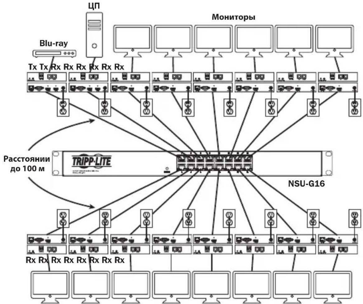
KpaTkoe onncahne yctaHOBKn (IJa BceX moJeN)
1.перд haayam yctahOBKn BCE noKlueyHoe obopydObaHne doJxHo 6bIb oecToyeho.
2. ПОДКЛЮЧITE NGTOUHн AYdno-/BnDEOCnHana K BXODHMy NOpTy NpepaOuIeRo MOnyJIa (BbInySCaEMbIe MoDEN aYdno-/BnDEoKa6eJe Tripp Lite nepeuNcIeHb I pa3deIe OOnuHaJIbHbIe KOMNKeKTyOuIe).
YCTaHOBka cMHOrToOueHoi TOnoIOrnei HeynpaBnaEmbI KOMMyTaTOP
- (Heo6aTeBho) CoeHnIte npT DB9 KOMbIepa c nocJeIOBaTeBbIM npToM nepeJaooero Moyra. B 3abucmocTu OT moJIe NocJeIOBaTeBbHbI npT MOKe T MeT b HTEpfeC DB9 nn 3,5 MM. MoJIe C pa3bemAmN 3,5 MM KOMPNeKTyOTc npExOHNKOM 3,5 MM — DB9. Iya noekluoyenr K KombIopepy moJene C npTaMn DB9 Tpe6yeTc c TaHapThbIKa6JIb c pa3bemAmR-232 u DB9 (npodaetc otJeBHo).
- (Heo6aTeNo) BCTaBbTe BbIXOHOI NK-Ka6eNb (IR-OUT) n3 KOMnEKeTa B npot IR-OUT nepeaoJero moyra. UcTahOBtte DaTuNK Ha Ka6eNb IR-OUT B CBO6OHom OT npenrTcbN MeCte TaKIM 06pa30M, uTo6bl ynpabJIeMoE yCTpoiCTBO HaxOINOCb B npedeJAX BuIMocTN. PpmeHne. Ka6eNb IR-OUT npHHMaet cRHaI dNCTaHIOHOrO ynpabJIeHn I nepeJaer erO Ha ynpabJIeMeOe yCTpoiCTBO (Hanpimep, npoiRpbIbATEb Blu-ray n np.).
- (Heo6aTeBho) IodKIOUHTe loKaIbHbM MoHITOp K BbIXOHOmy npTy HDMI nepeaIoJero moyra c nmoosbHDMI-ka6eJa (BbInyckaemble moJeHDMI-ka6eJe Tripp Lite nepeuCJIeHb B pa3dene OOnHOHaIbHbIe KomnneKtuyOuNe).
- UctaHOBtE XeHaembHOMep KaHana (oT 0 do 63) c nOmoU KhoNOK Up/Down (BBepx/BHN3) Ha nepeDHe NaneHn pePaTuKkA. Bce nepeDaTuKk, BXoJaUne B coCTab YcTaHOBKn, IOnJXHbl IMeTb pa3HbIe Homepa KaHaIOB.
PpmeHne. J3aHTbI OT cnyauHoro n3MeHeHn Homepa KaHana npedyCMOTpeMexAHnM fKcaun. Pn 3aФNKcnpOBaHHom Homepe KaHana ydepKuBaTe KhoNkUp (BBePx) NDown (BHN3) HaxaTbIMn Do tex nop, noka Homep KaHana He NaHT MraTb. 3aTe mpeiDte Ha xeJeaEMbI KaHAn C nomOu bIO KhoNOK Up/Down (BBePx/Bn3). IocNe Bbl6opa Jenaemoro Homepa KaHana 3aФNKcnpyIe erO, ydepXuBaJ KhoNkUp (BBePx) N Down (BHN3) do tex nop, noka Homep KaHana He npEkpATn MraTb.
- CoeHInTe BbIXoHoi nopT RJ45 (Output) nepeaIoIero MoIyra cOHNm nOpToB RJ45 ceTeBoro KOMMyTaTopa npn pOnOuN Ka6eJr Cat5e/6.
PpmeHne. MaKcMaJIbHO DoNyCTmJa DnHa Ka6eNa, CoeINHaIooero npMeHHK c KOMMyTaTOPoM, coCTaBnaT 100 M.

B 3TOT MOMENT nepedaTuk He doJxHe 6bITb noKluoyen K BHeuHemy 6nOky nHTaHna. NpedaTuk He cneJyET 3aNTbIBaTb Do noKluoyeHn I 3aNTbIBaHna BCEX 3JIeMeHTOB ayDNo-/BnDeo06OpyDoBaHna.
8.Дя nodklouhenno dononHntbHoro nepeaTnka NOBTOPe DeICTBnA,OnncAHhble Bnn.2-7.
YCTaHOBka cMHOrToOueHoi TOnoIOrnei HeynpaBnaEmbI KOMMyTaTOp
- Поdkлочte моннтор кaydno-/Видевьхody (Output) npneMHoro Modyna (BbInyckaemble Moden aydno-/Bndeoka6ene Tripp Lite cm.В pa3dene OOnhoHaBhbIe KOMnNeKtTuOuIe).
- (Heo6aTeNbHo) CoeHnIte npT DB9 noCneIOBateNbHO noKIOuAemoro yCTpoiCTBa c noCneIOBATENbHbIM npToM npHmHO ro MOyJRA. B 3aBucmOcTN OT moJIEN noCneIOBateNbHbIM npT MoKeT mMeTb nHTepfEic DB9 nn 3,5 MM. MoJIEN c pa3bemaMn 3,5 MM KOMJIeKtYOTc r nepexoHNkOM 3,5 MM — DB9. JIra noDknUeyHna yCTpoiCTBa K MoJIeM C npTAMn DB9 Tpe6yeTc r TaHdapThb KabEn b c pa3bemaMn RS-232 n DB9 (npOdaetc oTdenbHo).
- (Heo6aTeBho) BCTaBbTe BxOJHOI K-Ka6eJIb (IR-IN) u3 KOMnIeKTA B npT IR-IN npHemOr MoyIy. UcTaHOBtE DaTUnK Ha Ka6eJIb IR-IN B CBO6OJHom OT npEnrTCTBm MeCte TaKIM O6pa3OM, YTO6bl 6IOK dNCTaHOnOHoro ynpabJIeHn HaxOJINcR B npDeJax BNDIMOCtN.
PpmeHne. Kaebb IR-IN npHHMaet cunHan dctaHIOHoro ynpabHeHn I nepeaet ero ha ynpabIaeMOe yctpoCTBO, paonoloxehoe Ha nprom KOHcE yCTaHOBKN.
- UCTAHOBITE c nOMOJIbIO KHOJOK Up/Down (BBepx/BHn3) Ha nepeIeHne IaHeIe IpePaTuKHa HOpE KaHana (OT 0do 63), COBnaIauOuIc HOMepOM KaHana TOro nepeTaUKNa, Yei ayDIO-/BUNDeOCmRHaN Bbl XOTITe npINHMaTb.
PnmeaHne. 3aunb0 nuyauHoro nMeHnHn Homepa KaHana npdycmOTpeh MexaHnM 6nokpOBKn. Pn 3aKpOHOM Homepe KaHana yepxNBate KhoNkUp (Bbepx) uDown (BHN3) hxaTbIMu Do Tex nop, noka Hmep KaHana He NaHT MRAtb. 3aTe mpeiDte Ha Jekaembl KaHan c nomoubIO KhoNOK Up/Down (Bbepx/Bn3).Iocne BbIopa Jekaemoro Homepa KaHana 3aKcpyeero,yepxNBa KhoNkUp (Bbepx) u Down (Bn3) doTex nop, noka Hmep KaHana He pekpatnt MRAtb.
- CoeHInHe BbIXoHoi nopT RJ45 (Input) npneMHoro moyna c odHm u3 nopTOB RJ45 ceTeBOrO KOMMyTaTopa npn noMoUKN Ka6eN Cat5e/6.
PnmueyaHne. MaKcMaJIbHO DoNyCTMma JInHa Ka6e, CoeINHIOUeI npMeMHIK C KOMMyTaTOPOM, coCTaJIaRET 100 M.

B 3TOT MOMENT npHemHK He dOJxeh 6bITb NOdkIIOueH K BHeuHemy 6nOKy NHTAHNA.
PpHemHK He cIeUyET 3aNTbIBaTb Do NOdkIIOueHn I 3aNTbIBaHn BCEX
3JIeMeHToB ayDNo-/Bunde0o6OpyDoBaHn.
14.Дя nodknoeHnI dOONHHTeBhBIX npneMHKOB NOBTOPte DeICTBn,OnncAHbIe Bnn.9-13.
15. BkIIOUHTe NITaHHe BCEx IOdKIOUChENbIX yCTpoIcTB.
YCTaHOBka cMHOrToOueHoi TOnoIOrnei HeynpaBnaEmbI KOMMyTaTOp
BbIaBHeHne uYcTaPaeHne HeNCpPaBHOCTeI
EcnBbInonHeHne yka3aHn no yctaHOBKe He n03BOJAE TOnyUHTb npneMJeMo rKaueCTBa
H3o6paJxHn, nonpo6yIe BocnoJIb3OBAtBCr npuBeDEHHbIMn Hxke peKOMHaQaIaMn N O BblNeHIO u
yctpaHeHIO HeCnpabHOcte:
- Поdkлочьи Л noctabЯьсь B komпкte BheHnne 6LOKN NtAHN K pa6oTaOuSeMy nToUHKnY nHTaHn?Дя habлесацero ФункцюнрOBaHn DaHHOro n3dEIN OHO DoJXHo POKKIOUaTbCk K BHeHMeY 6LOKY nITaHn IN 3aNTbIbATbcr OT Hero.
- Было пи OTКлюсно ппане поКлючених устpoиCTBdo Нада установки?Есни.net,TOpe3anyCTITE BCE noKlJOчENHbIe ystpoiCTBa.
- 3aNTbIbAINCb IIN NOkIIOUeHHbIe aydno-/BnDeOyCTpoiCTBa Do 3aNTbIBAHNApepaioxN npemhbix Moyn? EcHn HET, OTCoeHNHTe NITaHne BCex nepeaIOxN INpneMbIX MOyJe, a 3aTeM 3aNTaTIe INx CHOBA.
- Kakoro pa3peuHn Bbl nbItaeTcB do6ntbca? POpO6Hee O MaKcMmaIbHbIX 3NaueHnx DnCTaHmN pa3peuHn CM. B pa3dJe ΦyHKUHOHaJIbHbIe BO3MOXHOCTN N3DeHn HactoJrero pykoBOIDCTBa. B clyuae HeBO3MOxHOCTN noLyueHn npneMlEmoro KaYeCTBa N3o6paXeHn nonpO6yute yMeHbIITb BIndeopa3peuHne KOMNbIOTepa IIIN OTPeyIpOBaTb YactOTy o6HOBLeHn.
- KaKoro TUna Ka6eHn NcNoB3yOToC B DaHNoY cTaHOBKe? NcNoB3oBaHne HeHaJIeXaUx Ka6eHm MoKeT npVBecTN K yxydIeHNIO pa6OuNX xapakTePncTnK. Heo6xoJIMo NcNoB3oBaTb Ka6eHn, NoIepXnBAOUIne Huxhbl ypoBeHb BVdeOpa3peWeHn. IInr DoCTNKeHn MaKcMaJIbHOH dNCTaHcUNI paopeHHeo6xoJIMo NcNoB3oBaTb Ka6eNB Cat5e/6 c OAnHOxNlBbIMn IpBOaAMn KaIb6pa 0,2 MM²nn Cat6a COnHOxNlBbIMn IpBOaAMn KaIb6pa 0,26 MM². Ka6eHn Cat6 cepIN N202 MapKn Tripp Lite n3rotabNAOTc C NcNoB3oBaHnEM OAnHOxNlBbIX IpBOaOB KaIb6pa 0,2 MM², tAK Jek KaN Ka6eHn B 6yxtax N022-01K-GY (Cat5) n N222-01K-GY. NcNoB3yEmbIe ayDINO-/BVdeOka6eHN TaKxe DOnJKNbI PoJaepXnBaTb HyxHbI ypoBeHb BVdeOPa3peHnE. DeSeBbIe IN Hn3KOKaueCTBeHHbIe Ka6eHN MOyT He NpIoepXnBaTb MaKcMaJIbHOrO pa3peWeHn. PekOMeHNyETc NcNoB3oBaTb Ka6eHN MapKn Tripp Lite, nepeuNCleHHbIe B pa3dene OnCuHOaNbHbIe KomNNeKtTyOuune NaCTOJeRO pykoBoDCTBa.
- Поберпснольземье кабели на педmetхн НадлжашERO Функцонровань. Hanprimep, Дя поверки Истразвости aydno-/Видевая сөдүнөт ueрз Hero paobotшпп мочник и монлтор. Дя поверки кабеля Cat5e/6 ha obecne�ене ceteBOrO coedinhenny рokkluoyte сэрп поюсыю komlbуTeR K CETN.
BbIaBHeHne uYcTpaHHe HEnCnpaBHOCTeI
- Пюверы Кабени на пемет наличая пораздени, которь мори npon30нВ почесустановки.В сунае разбалыня Кабелбого разьема пи пotягвани Кабеля чера сень /notолкни пораздени Кабелбого облочки, Вьзьвадцero оrolенye пювдов, достхжени мakсимальных разочи Характетснк He педставаясь BO3MOxныm.
- He noDBepraTcra IIN nepeaTCHK(-n) n/nn npHemHuk(-n) BO3dEChTBIO NOBblIeHHbIX TemnepaTyp B Tex MecTx, rDe OHN yCTaHOBNeHb! B cnyae neperpeBa n3dJeNHe Me MoKeT φ YHKUHOHPoBaTb HaJIeKaUIM 06pa3OM.
- He yctaHaBnBaIe OndHaKOBbie Homepa KaHAnOB IJIpePeTaUKNOB B UCTaHOBKe C nOJb30BaHHeM HeynpaBnEmoro KOMMyTaTopa. 3TO npuBeTe KOTcYCTBnIO OT6paXeHnA cIHana Ha MOHTopax, POKJIIOueHHbIX K npneMnKam, HAcTpoEHHbIM Ha KaHaNBI C OINHaKOBbIM Homepom. B 3tOM clyae IN3MeHIne Homepa KaHAnOB nepeDaTuNKOB Ha YHKaJIbHbIe IN AcTPOIte yKa3aHHbIe npneMnKn Ha KaHaNBI C HxKhbIMn HomepaMn. EcnI nocIe BvIpOnHeHnEA Tnx DeiCTBn ayDINO-/BVIDoeOCnHaN He BOCCTaHaBnBAeTCR, OTKIOUHTe NITaHne COOTBeTCTByUoNix NepeDaTuNKOB IN npneMnKOB IN pOKJIIOUHTe erO CHOBA NO ICTeUeHN10 cekyHd.
- He podknoyaTe 6oee DByx nepedaTchkoB ByCTaHOBKe CnOJb3OBAHEm HeynpabMaMOro KOMMyTaTopa. KoInueCTBO nepedaTchkoB ByCTaHOBkax C HeynpaBJaEMbIM KOMMyTaTopom OrpaHnUbaetc DaYm, a KOInueCTBO npuemHHKOB — YIClOM OCTaBUnXcR nopTOB HeynpaBJaEMoro KOMMyTaTopa.
- He nodknoaute K cTeBomy KommyTaTopy KaKoe-Im6o dpyroe cTeBoe o6OpydoBaHne. IP-petpahncIantopb aydno-/BvdeocnHaNoB cepin B160 npedna3nauoTcJn IcnoJIb3OBAHn C BblJeHHbIM cTeBBIM KOMMyTaTOpom.Vx noDKnUoyHeNk K KomMyTaTopy, nCNOb3yeMOMy C dpYrIM cTeBBIM 6OpuyoBaHneM, npuBeTe K yxydWeHIO xapaKTepnCTIK n3DeJIINn IIN erO noJHOH hep60tocnoc6hOCTN.
TapaHTnHbIe 06a3aTeNbCTBa
Iapantma 1 ro
Kompana Tripp LepaTupyet OTCYCTBNE dekeKOB MaTePnAnOB IN3ROTOBHeN B TeueHne OJHO (1) roda cMoneHa TepBOHaJIbHO NOKynm. 063aTeIbCTBa Kompana Tripp Lite no Hactoae rapaHTn ORpAHUINBAOTcpeMOTHOM nIIN 3aMeHNO (no ee eJINHOHNHYOM yCMOTpeHHIO) IIO6bx TaKHX deeKTHbIX u3denn. IIN NOUYEHNA YCyr no daHNo rapaHTn HeO6XoDMIO NOUYHTb Homep Returneded Material Authorization (RMA - papeuHne Ha BO3BPAT MaepanAO) ot Kompana Tripp Lite nIIe ee ABTOPAOBAHORo cepBCNHO OENTpa. N3dEINr DOJIKHBs 6bIT Bo3BpaueHb KOMPAHNO Tripp Lite nIIe ABTOPAOBAHBI CEPBNCBI CEHTRP Tripp Lite cnpdoNtaoTPOAHCNPbHx paCXOIO B CONPOBQDaTcK pATKM ONCAHEM BO3HKWIE np6bEMBI INDOKUMeHTOM, NOITBePjDAUIM DaTy IM MeTo Ero pIno6peTeHHIA. DeiCTBNE HAToTae rapaHTM He pacnpoCTpaHReTcHa 6bI To Hn 6blIO 6pa3OM.
3A NCKJIIOUHEM IPEJYCMOTPEHHbIX 3DcB CUYAEB KOMIANHIA Tripp Lite HE IPEIOCTABJRET KAKNX-JI50 ABHBix INI NIOPA3YMEBAEMbIX TAPAHNTBI, BKIIOUAR TAPAHNTM KOMMEPUECKO INIPIROHOCTUN INIPIROHOCTN INI KAKOIN-1I50 KOHKPETHO CEIN. B HeKOTopbIX Wtatax/ ROCyapdCTbX ORpAHueHne INI NCKIOUHHe NOpa3yMeBaEMbIX TAPAHNT He DOpyCAeTC; cIeIOBATEbHo, BbiyeKa3aHHe(-bie) OrpAHueHne(-i) INI NCKIOUHHe(-r) MOrTy He paocptpaHbTaHa NokyaTeJI.
3A NCKJIIOUHEM IPEYCMOTEHBx BbIe CUYAEB KOMPAHNA Tripp Lite HN INPNI KAKNX OCBTORENTBCTBAX HE HECET OTBETCTBEHHOCTN 3A IPIRMBIE, KOCBEHNBIE, CUYAHNBIE ININ IOBOUHBE YbIbTKN INbO bSbITK, ONPDEJENMBI EOCbIMN OCBTORENTBAMN, BO3HKAIUHNE B CBA3N CNCIOJIb3OBAHNE DAHHORO IN3DEINIA, DAXE B CNYAE EE INHOPMIMPOBAHNA O BO3MOXHOCTN HACTYNIIEHNA TAKNX y5bITKOB. B cactHOCTn, KOMPAHNA Tripp Lite He HeceT OTBcTBHeHNOCTN 3a KaKNe-Inbo IN3dpejKKn, TaKe KaK yNuJeHNbIe pInbblnn Nn DoxoDb, NOtep aobpyoBaHna, notep Bo3MOXHOCTN INCIOB3OBaHNA o6OpyDobHa, notep nporpaMMHO o6cneueHna, notep daHHbx, paXOdb Ha 3aMeHHTeIN, yperynipOBaHne pTeH3n TpebNx Inu np.
KomnaHn Tripp LioctoAnHO COBepueHCTByET CBOK npOykuu. B CB3N c 3mM BO3MOKHO 3meHeHneTexHuecknx XapakTePcNTk 6e3 npedBaupntbHorO yBeDOMJIeHn. BHeHn Bn peaIbHbIX n3dEIN MoKeT HeCKoJIbKO OTnpeCTabNeHHORo Ha foToTpaJHX nIIIOCTpauixx.


PpOyEeH BueuCIO
1111 W. 35th Street, Chicago, IL 60609 USA • www.triplite.com/support
19-05-366 93-36B2 RevB


- Audio/Video with RS-232 and IR Control over IP Extenders
- WARRANTY REGISTRATION
- Package Contents
- Optional Accessories
- Product Features
- Mounting Instructions
- Point-to-Point Installation
- Notes:
- Point-to-Multipoint Installation - Managed Switch with IGMP
- Operation of Point-to-Multipoint Installation - Managed Switch with IGMP
- Point-to-Multipoint Installation - Unmanaged Switch
- Point-to-Multipoint Installation – Unmanaged Switch
- Installation Overview (All Models)
- Do not connect the external power supply to the transmitter at this time. The transmitter should not be powered on until all audio/video equipment is connected and powered on.
- Do not connect the external power supply to the receiver at this time. The receiver should not be powered on until all audio/video equipment is connected and powered on.
- Troubleshooting
- Warranty and Product Registration
- 1-Year Warranty
- PRODUCT REGISTRATION
- FCC Notice, Class B
- PykoBODCTBO N0Ib30BaTeJia
- PetpancIaTOpbl aydno-/BndeocnHaIa c pa3bemom RS-232 n IK-ynpaBleHneM no npotoKoIy IP
- Modell petpansTopoB B
- Moden
- TRIPP·LITE
- CopejxHmoe ynaKOBKn
- OngnohaIbHbIe KOMnIeKtYuOuIe
- XapakTepeNCTnKn npOdyKta
- HnctpyKzno moHTaKy
- YCTaHOBka C DByXToUeHOn TOnOJOrNeI
- Примочаня:
- YCTaHOBka cMHOrToOueHoi TOnoIornei—YnpaBJIeMbIKOMMyTaTOP CnCIOJb3OBAHHeM npoTOKoJa IGMP
- Pa60ta yCTaHOBKn C DByxTOueHNo TOnOJOrNe - YnpaBnaembI KOMMyTaTOP cNcNoJIb3OBaHnEm npToKoJa IGMP
- Приимechanical:
- Pa60ta yCTaHOBKc DByxToueHNo TOnoJOrney - YnpaBnaembI KOMMyTaTOP CnOJIb3OBAHHeM npToKOJa IGMP
- YCTaHOBka c MHOrOToUcHNo TOnoIOrNei HeynpabJIeMbI KOMMyTaTOp
- PpIMeuaHn:
- YcTaHOBKa CMHorOToUcHOn TOnoIOrNe- HeynpabIeMbI KOMMyTaTOp
- YCTaHOBka cMHOrToOueHoi TOnoIOrnei HeynpaBnaEmbI KOMMyTaTOP
- BbIaBHeHne uYcTaPaeHne HeNCpPaBHOCTeI
- BbIaBHeHne uYcTpaHHe HEnCnpaBHOCTeI
- TapaHTnHbIe 06a3aTeNbCTBa
- Iapantma 1 ro
Brand : Tripp Lite
Model : B160201HSI
Category : Receiver