PDUMNH20HVAT - Power strip Tripp Lite - Free user manual and instructions
Find the device manual for free PDUMNH20HVAT Tripp Lite in PDF.

User questions about PDUMNH20HVAT Tripp Lite
0 question about this device. Answer the ones you know or ask your own.
Ask a new question about this device
Download the instructions for your Power strip in PDF format for free! Find your manual PDUMNH20HVAT - Tripp Lite and take your electronic device back in hand. On this page are published all the documents necessary for the use of your device. PDUMNH20HVAT by Tripp Lite.
USER MANUAL PDUMNH20HVAT Tripp Lite
- Important Safety 2 Instructions
- Installation 3
2.1 Mounting the ATS 3
2.2 Connecting the ATS 5
2.3 Networking the ATS 6
- Features 6
- Digital Display 8
- Using the Digital Display 10
5.1 Navigating Display Menus 10 and Submenus
5.2 Navigating Config Menus 13 and Submenus
- Configuration and Operation 15 6.1 Automatic Transfer Switch 15
- Service 17
- Warranty and Product 18 Registration
Español 19
Français 37
Русский 55
PROTECT YOUR INVESTMENT!
Register your product for quicker service and ultimate peace of mind.
You could also win an ISOBAR6ULTRA surge protector—a \$100 value!

text_image
QR code image containing encoded data, no visible human-readable textwww.tripplite.com/warranty

text_image
TRIPP·LITE
1111 W. 35th Street, Chicago, IL 60609 USA • www.tripplite.com/support
Copyright © 2015 Tripp Lite. All rights reserved.
1. Important Safety Instructions
SAVE THESE INSTRUCTIONS
This manual contains instructions and warnings that should be followed during the installation, operation, and storage of this product. Failure to heed these instructions and warnings may affect the product warranty.

- The ATS provides a convenient dongle outlet, but it DOES NOT provide surge or line noise protection for connected equipment.
- The ATS is designed for indoor use only, in a controlled environment, away from excess moisture, temperature extremes, conductive contaminants, dust or direct sunlight.
- The ATS can only be used in a Restricted Access Location where access can only be gained by qualified service personnel.
- Keep indoor ambient temperature between 32^ and 122^ (0°C and 50°C).
- The ATS must be installed by a qualified technician only.
- Do not attempt to mount the ATS to an insecure or unstable surface.
- Install in accordance with National Electrical Code standards. Be sure to use the proper overcurrent protection for the installation, in accordance with the plug/equipment rating.
- Connect the ATS to an outlet that is in accordance with your local building codes and that is adequately protected against excess currents, short circuits and earth faults.
- Do not power on and use the ATS with one plug exposed.
- The electrical outlets supplying power to the equipment should be installed near the equipment and easily accessible.
- Do not connect the ATS to an ungrounded outlet or to extension cords or adapters that eliminate the connection to ground.
- Be sure to provide a local disconnect device on any models that are permanently installed without a plug that is easily accessible.
- Disconnect both AC input sources before servicing ATS unit.
- Never attempt to install electrical equipment during a thunderstorm.
- Individual equipment connected to the ATS should not draw more current than the individual outlet's rating.
- The total load connected to the ATS must not exceed the maximum load rating for the ATS.
- Do not attempt to modify the ATS, input plugs or power cables.
- Do not drill into or attempt to open any part of the ATS housing. There are no user-serviceable parts inside.
- Do not attempt to use the ATS if any part of it becomes damaged.
- Use of this equipment in life support applications where failure of this equipment can reasonably be expected to cause the failure of the life support equipment or to significantly affect its safety or effectiveness is not recommended. Do not use this equipment in the presence of a flammable anesthetic mixture with air, oxygen or nitrous oxide.
2. Installation
2.1 Mounting the ATS
The ATS supports 1U rack configurations.
Notes:
- The instructions described in this guide are for common rack and rack enclosure types and may not be appropriate for all applications. The user must determine the fitness of hardware and procedures before mounting. If hardware and procedures are not suitable for your application, contact the manufacturer of your rack or rack enclosure for a solution.
- The user must determine the fitness of hardware and procedures before mounting. The PDU and included hardware are designed for common rack and rack enclosure types and may not be appropriate for all applications. Exact mounting configurations may vary.
- Rackmount equipment may be extremely heavy—be careful when moving or lifting equipment. Use one or more assistants if necessary.
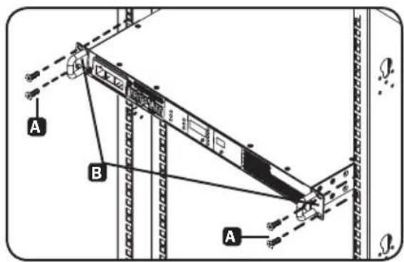
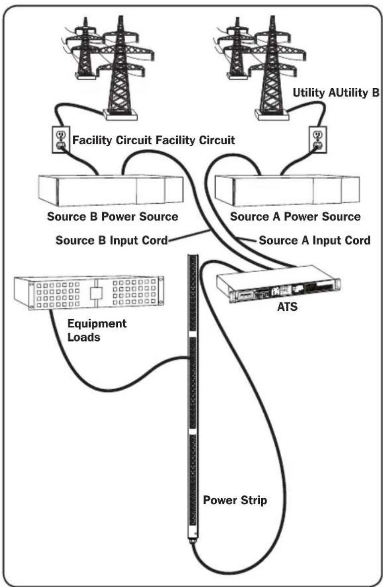
2.1.1 1U Rack Mounting
Attach the PDU to the rack by inserting four user-supplied screws A through the PDU mounting brackets B and into the mounting holes of the rack rail as shown.
text_image
A B A2.1.2 Rear Rack Rail Kit Installation
For additional stability, a front and rear rail kit can be used for rack mount installations. This kit is included for models PDUMNH30HVAT and PDUNH32HVAT, but can also be purchased separately for models where it is not included.
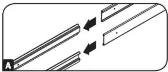
Disassemble the Bracket Sets
Note: This rail kit is only compatible with a 4-post rack or rack enclosure.
A Disassemble each bracket set by sliding them apart.
natural_image
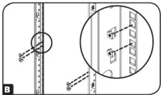
Diagram showing two parallel lines with arrows indicating direction, no text or symbols presentAttach Rear Rail Segments to the Rack
B Insert two cage nuts (provided with your rack enclosure) on each of the rear vertical mounting rails of the rack enclosure at your desired location.
natural_image
Technical diagram showing a mechanical assembly with a circular component and an inset close-up of a vertical panel (no text or symbols)2. Installation
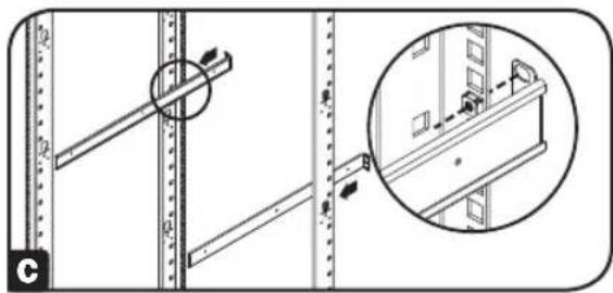
c Align the rear segments of the bracket set with the cage nuts.
natural_image
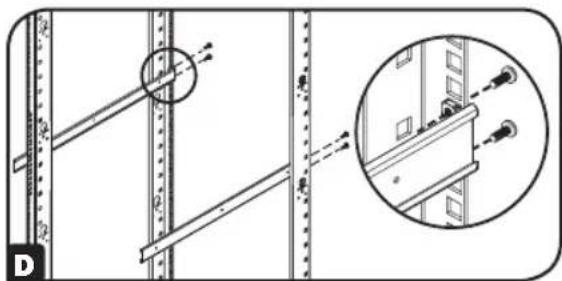
Technical diagram showing structural components with a magnified inset of a building detail (no text or symbols)D Insert and tighten four Phillips pan-head screws (provided with your rack enclosure).
natural_image
Technical diagram showing structural components with an inset magnified view of a detail (no text or symbols present)Attach Front Rail Segments to the Automatic Transfer Switch
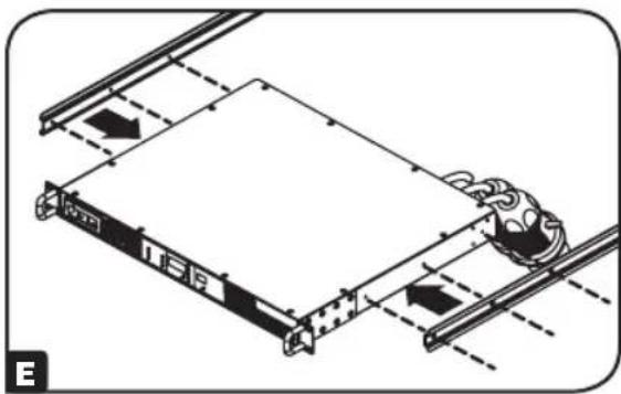
E Align the front rail segments of the bracket set with the corresponding holes located on the sides of the Automatic Transfer Switch (ATS).
natural_image
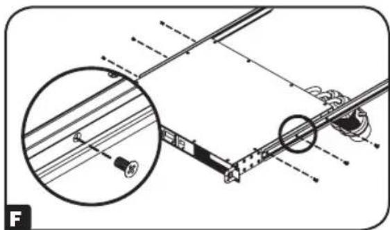
Technical diagram of a mechanical assembly with rotating components and directional arrows (no text or symbols)F Attach both front segments to each side of the ATS using six Phillips flat-head screws (included).
natural_image
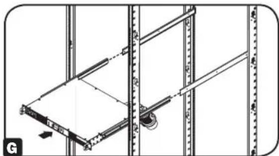
Technical diagram of a mechanical assembly with an inset showing a close-up of a component (no text or symbols present)Install the Automatic Transfer Switch in the Rack Enclosure
Note: Two people should perform this procedure.
G Position the ATS in front of the mounted rear rail bracket segments.
natural_image
Technical line drawing of a mechanical assembly with vertical supports and a central component (no text or symbols)2. Installation
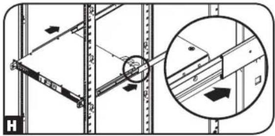
H Align the front and rear bracket segments and slide the front rail segments onto the rear rail segments.
1 Align the mounting ears on the ATS with the front vertical mounting rails of the enclosure. Then insert and tighten four Phillips flat-head mounting screws with cup washers (provided with your rack enclosure).
2.2 Connecting the ATS
2.2.1 Connect ATS Input Plugs
Note: The ATS comes equipped with two AC power inputs: Source A and Source B. Source A is the default preferred (primary) source. See Navigating Config Menus and Submenus section for instructions on changing the preferred source. The connection instructions below assume Source A is the preferred source.
Connect the Source A input plug A to a preferred AC power source. Under normal operating conditions, the ATS will provide AC power from the Source A input source. Connect the Source B input plug B to an alternative source of grounded AC power. Do not plug the Source B input into the same power source as the Source A input. The ATS will provide AC power from the Source B input only if the Source A input becomes unavailable or unstable.
2.2.2 Connect Equipment to the ATS
Do not exceed the load rating of the ATS. The electrical current used will be displayed in amperes on the digital meter.
natural_image
Technical diagram showing mechanical assembly with a magnified inset of a bracket detail (no text or symbols)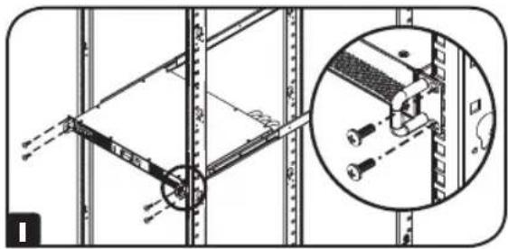
natural_image
Technical diagram showing a mechanical assembly with a magnified inset of a bracket detail (no text or symbols)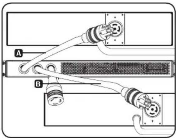
natural_image
Diagram of a network device showing two connected cables (labeled A and B) with connectors, no text or symbols present.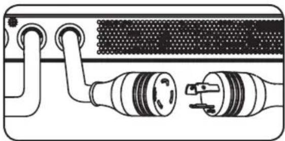
natural_image
Diagram of a device showing two connected components with no visible text or symbols2. Installation
2.3 Networking the ATS
Your ATS can receive its IP address assignment via DHCP server (dynamic) or static (manual) addressing methods. If you are uncertain which method to use, contact your network administrator for assistance before continuing the configuration process.
Note: The MAC address (12-digit string in this format: 000667xxxxx) is printed on a label and attached to the ATS enclosure. For static IP address assignment, use the DB9 configuration cable (730866) included with the ATS.
The ATS provides remote monitoring and more via Web browser, telnet and SNMP-based Network Management Systems. For more information about configuration and operation of the ATS via the PowerAlert Web browser interface, refer to the SNMPWEBCARD User's Guide by going to www.triplite.com/support and typing SNMPWEBCARD into the search field.
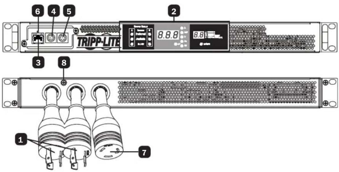
3. Features
text_image
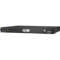
6 4 5 2 TRIPP-LITE 8.8.8 8.8 7 3 8 11 ATS Source A and Source B Input: The cords are permanently attached to the ATS. The following plug types are used for each model:

IEC 309 16/20A BLUE (2P + E)*

NEMA L6-20P NEMA L6-30P IEC 309 32A


BLUE (2P + E)
| Model Input Plug Type Output Receptacle Type | |
| PDUMNH16HVAT IEC 309 16/20A BLUE (2P + E)* IEC 309 16/20A | |
| PDUMNH20HVAT NEMA L6-20P NEMA L6-20R | |
| PDUMNH30HVAT NEMA L6-30P NEMA L6-30R | |
| PDUMNH32HVAT IEC 309 32A BLUE (2P + E) IEC 309 32A |
*Dual-agency rated plug
3. Features
2 Digital Display: Shows source status, measured values, display modes and other information. See the Digital Display section for detailed explanations of the indicators and displays.
3
Network Interface: Use the RJ-45 jack to connect the ATS to the network with a shielded Ethernet patch cable. The Status LED A and Link LED B indicate operating conditions as shown in the table below. These ports are not compatible with PoE (Power Over Ethernet) applications.
Network Interface: Use the RJ-45 jack to connect the ATS to the network with a shielded Ethernet patch cable. The Status LED A and Link LED B indicate operating conditions as shown in the table below. These ports are not compatible with PoE (Power Over Ethernet) applications.
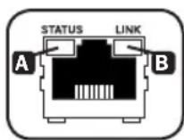
| Network Operating Conditions | |||
| A Status LED Color | B Link LED Color | ||
| Off Card Not Initialized Off No Network Connection | |||
| Steady Green Card | Initialized and Operational Flashing | Amber 100 Mbps | Network Connection |
| Flashing Amber Error - Card Not Initialized Flashing Green 10 Mbps Network Connection | |||
4 Mini-DIN Serial Port: Use this port to provide a direct terminal connection to a computer with a terminal emulation program.
5 PS/2 Port: Use this port to connect a Tripp Lite ENVIROSENSE environmental sensor to provide remote temperature/humidity monitoring and a dry contact interface to control and monitor alarm, security and telecom devices.
6 SNMP Reset Button: Press the reset button for 3 seconds to reboot the ATS network card. Rebooting the network card will not erase network settings or interrupt AC power. The reset button is recessed. Use a paper clip or other suitable object to press it.
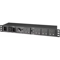
7 ATS Output: This cord is permanently attached to the ATS (see chart on pg. 4).
8 Chassis Ground Screw: Use this to connect equipment that requires a chassis ground.
4. Digital Display
text_image
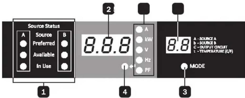
Source Status A Source B Preferred Available In Use 1 2 8.8.8 A kW V Hz PF 4 8.8 A - SOURCE A b - SOURCE B C - OUTPUT CIRCUIT t - TEMPERATURE (C/F) MODE 31 Source Status LEDs: Lit LED patterns indicate which source is preferred, which are available for use, and which is currently being used. See Source Status LED Indicators section for an explanation of the LED patterns.
2 3-Digit Display: Shows measured or calculated values such as Amperage, Kilowatts, Voltage, Frequency, Power Factor and Temperature.
3 Mode Button: Scroll through the Display and Config menus using this button. Display menu choice is shown on 2-digit display. Config menu choice is shown on 3-digit display.
4 Enter Button: When a menu is selected using the Mode Button, the Enter Button scrolls through the submenus within each category. Submenus are shown by the Indicator LEDs. Note: Pushing the Enter and Mode button simultaneously for 2 seconds displays the IP address.
5 Indicator LEDs: Lit LED indicates which value is being displayed on the 3-digit screen.
Amps (A): The input current on the selected Source Input (A or b) or Output Load Circuit (C) is displayed in amps.
Wattage (kW): The Output Power for the Output Load Circuit (C) is displayed in kW.
Voltage (V): The Source A or B Input voltage (A or b) or Output Load Circuit voltage (C) is displayed in volts.
Frequency (Hz): Source Input A or B frequency is displayed in Hz.
Power Factor (PF): Output Load power factor is displayed as a decimal (from 0 to 1.00).
6 2-Digit Display: This display indicates which display mode is selected: Input Source (A or b), Output Circuit (C), or Temperature (tC or tF).
Source A (A): Displays measurements for Source A. They include current (A), Voltage (V) and Frequency (Hz).
Source B (b): Displays measurements for Source B. They include current (B), Voltage (V) and Frequency (Hz).
Output Circuit (C): Displays measurements for Output Circuit. They include Current (A), Kilowatts (kW), Voltage (V) and Power Factor (PF).
Temperature (t): The ambient temperature is displayed when this option is selected. The temperature is displayed in Celsius by default, but can be switched to Fahrenheit.
4. Digital Display
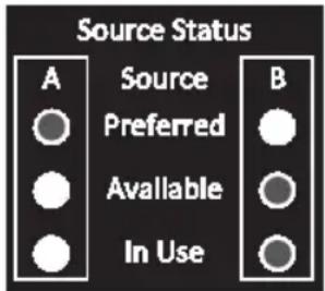
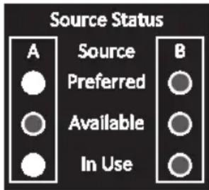
Source Status LED Indicators
LED pattern Description
text_image
Source Status A Source B Preferred Available In Use
Lit LED

Unlit LED
text_image
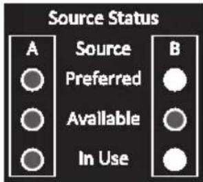
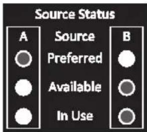
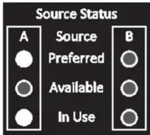
Source Status A Source B ● Preferred ○ ○ Available ○ ● In Use ○- Source A preferred
• Both sources of good quality and available
• Output is connected to Source A
text_image
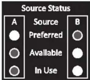
Source Status A Source B Preferred Available In Use- Source B preferred
- Both sources of good quality and available
• Output is connected to Source B
text_image
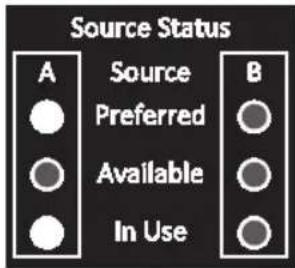
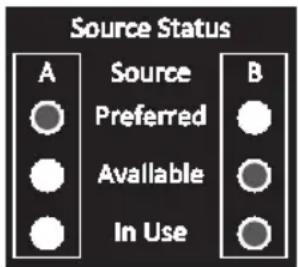
Source Status A Source Preferred Available In Use B- Source A preferred
-
Source A is of poor quality or unavailable
• Output is connected to Source B -
Source B preferred
- Source B is of poor quality or unavailable
• Output is connected to Source A
5. Using the Digital Display
5.1 Navigating Display Menus and Submenus (Measurement)
Press the MODE button to go to the next Display menu. Press the Enter button to go to the next submenu (Amps, kW, Volts, Hz, PF). Press and hold MODE button for 2 seconds to switch to the first Config menu (Refer to Navigating Config Menus and Submenus section). Press and hold both the MODE and Enter button for 2 seconds to show the IP address of the connected SNMP card. The scrolling pattern of the menus is outlined below.
Source A
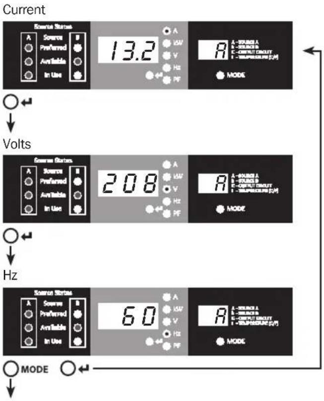
text_image
Current Source Status A Preferred Available In Use 13.2 A L-VALUE A E-VALUE B C-OUTPUT CIRCUIT F-TEMPRESSURE (CM) MODE Volts Source Status A Preferred Available In Use 208 A L-VALUE A E-VALUE B C-OUTPUT CIRCUIT F-TEMPRESSURE (CM) MODE Hz Source Status A Preferred Available In Use 60 A L-VALUE A E-VALUE B C-OUTPUT CIRCUIT F-TEMPRESSURE (CM) MODE MODE5. Using the Digital Display
Source B
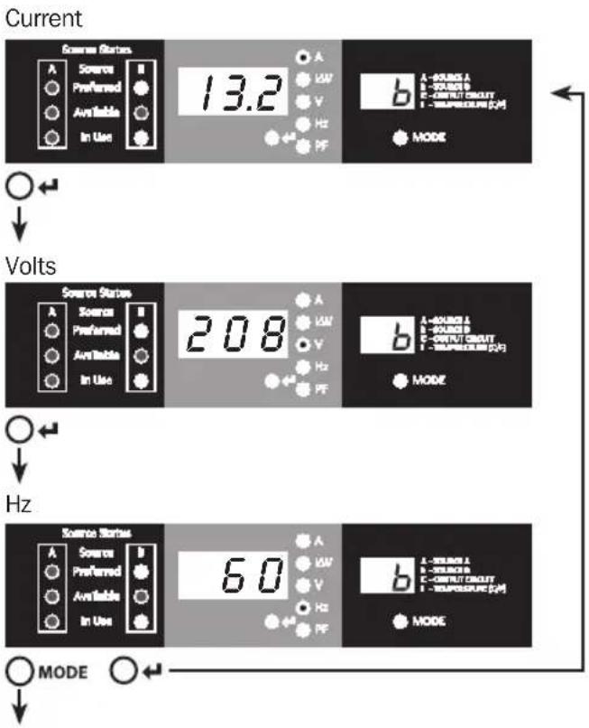
text_image
Current Source States A Preferred Available In Use 13.2 A VW V Hz PF b A-SPRING A B-SPRING B C-CURRENT CIRCUIT D-TSUPERCURE [Ω] MODE Volts Source States A Preferred Available In Use 208 A VW V Hz PF b A-SPRING A B-SPRING B C-CURRENT CIRCUIT D-TSUPERCURE [Ω] MODE Hz Source States A Preferred Available In Use 60 A VW V Hz PF b A-SPRING A B-SPRING B C-CURRENT CIRCUIT D-TSUPERCURE [Ω] MODE MODEOutput Load Circuit
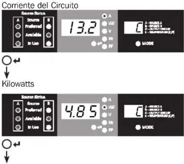
text_image
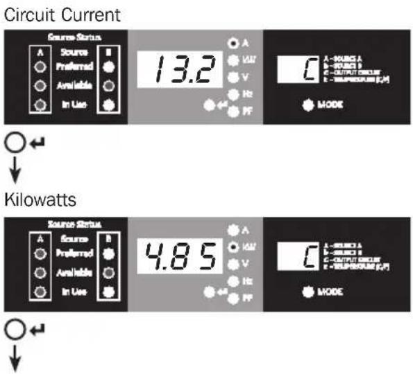
Circuit Current Source Status A Source Preferred Available In Use 13.2 A VW V Hz PF A - KURG A B - KURG B C - OUTPUT SOUT D - PULSEOR [J] MODE Kilowatts Source Status A Source Preferred Available In Use 4.85 A VW V Hz PF A - KURG A B - KURG B C - OUTPUT SOUT D - PULSEOR [J] MODE5. Using the Digital Display
text_image
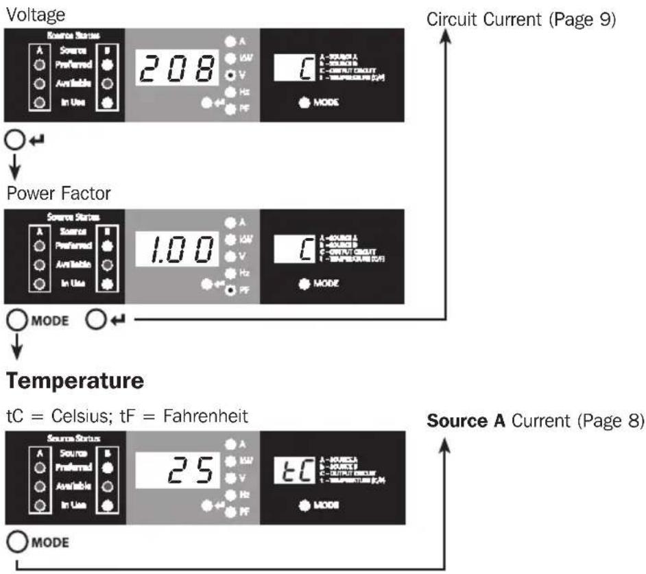
Voltage 208 A VW V Hz PF C A - SOURCE A B - SOURCE B C - OUTPUT CIRCUIT D - TEMPERATURE (pA) MODE Power Factor 1.00 A VW V Hz PF C A - SOURCE A B - SOURCE B C - OUTPUT CIRCUIT D - TEMPERATURE (pA) MODE Temperature tC = Celsius; tF = Fahrenheit 25 A VW V Hz PF C A - SOURCE A B - SOURCE B C - OUTPUT CIRCUIT D - TEMPERATURE (pA) MODE Source Status A Preferred Available In Use Source Status A Preferred Available In Use Source Status A Preferred Available In UseIP Address Display
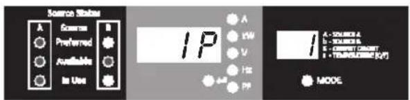
At any time you can press and hold both Mode and Enter buttons for 2 seconds to show the IP address of the connected SNMP card. The 3 digit display will show "IP". The 2 digit display to the right of it will show one IP address digit at a time until it shows the entire IP address. Decimal points and colons will be shown as hyphens. Note: This display supports IPv4 AND IPv6 addresses. The display will automatically transition back to whatever mode it came from after displaying the IP address.
text_image
Source Status A Preferred Available In Use IP A 1W V HZ 4# PP MODE A - COLOR A B - YELLOW C - CMYCH (CMY) D - TEMPERATURE (KJ/T)5. Using the Digital Display
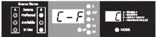
5.2 Navigating Config Menus and Submenus (Configuration)
While in any Display Menu, press and hold Mode button for 2 seconds to enter the first Config menu. Press Mode button to cycle to the next Config menu. Press and hold Mode button for 2 seconds to switch to Display menus.
Temperature Unit Options
text_image
Source Status A Preferred Available In Use E - F A V Hz PF F A - B: 0.05 A B - C: 0.01 B C - D: 0.04 C D - E: 0.02 D E - F: 0.03 E F - G: 0.04 G MODE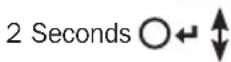
text_image
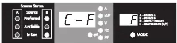
Source Status A Preferred Available In Use C - F A UW V Hz PF MODE A - SOURCE A - SOURCE B E - OUTPUT CIRCUIT - TEMPERATURE [J/V]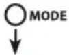
Preferred Source Selection
text_image
Source Status A Sorion Preferred Avr Value In Use P S S A LOW V Hz PF B A - MAXING A A - MAXIMUM B C - OUTPUT CIRCUIT I - TEMPERATURE (dB) MODE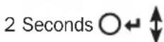
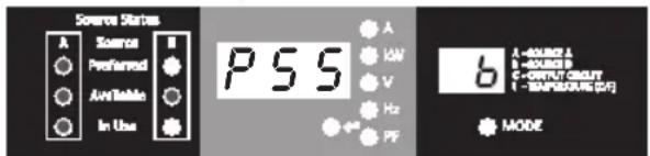
text_image
Source Status A Preferred Available In Use PSS A LOW V Hz PF b A - RADIUS A B - RADIUS B C - OUTPUT SQUITY D - TEMPERATURE (dB) MODE
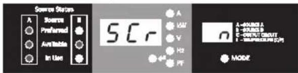
Auto Scroll Enable/Disable
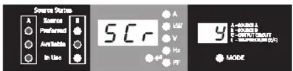
text_image
Source Status A Source B Preferred Available In Use 5Cr A LAM V Hz PF 9 A - KONOR L B - KONOR P C - OUTPUT CMNT D - MOUNTED (0円) MODE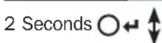

text_image
Source Status A Preferred Available In Use SCR A UAV V Hz PF A-ROUNES A - ROUNES B C-OUTPUT SMOY - MULTIPRODUM (CM) MODE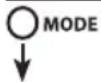
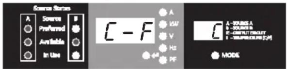
Hold Enter button for 2 seconds to switch between options. The letter in the 2-digit display indicates the selected unit, C for Celsius and F for Fahrenheit.
Hold Enter button for 2 seconds to switch between Source A and Source B. The letter in the 2-digit display indicates the selected source.
Note: If both sources are available, the unit will transfer to the preferred source immediately once the setting is changed.
When enabled, the Auto Scroll function changes menus in 4-second intervals. "y" indicates the function is enabled; "n" indicates that it is disabled. Pressing any button interrupts the auto scroll function, allowing the user to navigate between menu options. If no button is pressed, there is a 10 second timeout and auto scroll will resume from the current menu.
5. Using the Digital Display
LED Brightness
Hold the Enter button for 2 seconds to scroll through each brightness option. The number in the 2-digit display is defined as: 1=25%; 2=50%; 3=75%; 4=100%.
Note: The default brightness option is 4 (100%).
flowchart
graph TD
    A["Source Status"] --> B["LED"]
    B --> C["4° MODE"]
    D["Source Status"] --> E["LED"]
    E --> F["1° MODE"]
    G["Source Status"] --> H["LED"]
    H --> I["2° MODE"]
    J["Source Status"] --> K["LED"]
    K --> L["3° MODE"]
    M["Source Status"] --> N["LED"]
    N --> O["MODE 2 Seconds"]
LED Test

text_image
Source Status A B Preferred Available In Use t S t A HV V Hz +4 PF A - KONICA B - KONICA C - OUTLET CIRCLE T - TEMPERATURE (GPa) NODE 2 Seconds ○← Source Status A B Preferred Available In Use 8.8.8. A HV V Hz +4 PF A - KONICA B - KONICA C - OUTLET CIRCLE T - TEMPERATURE (GPa) NODE MODEHold Enter button for 2 seconds to start an LED test. All LEDs will illuminate for 6 seconds.
Temperature Unit Options (Page 11)
6. Configuration and Operation
6.1 Automatic Transfer Switch
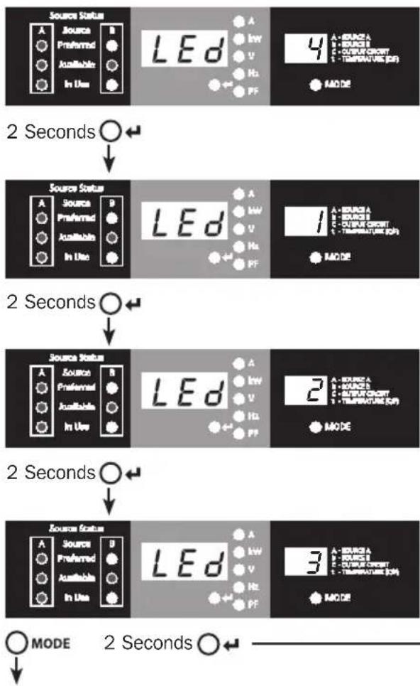
When the Source A and Source B inputs are both connected to power sources, the ATS operates as an Automatic Transfer Switch, providing redundant input power for high availability applications. The ATS will distribute power from the preferred input source under normal operating conditions and switch to the other input source under abnormal conditions. The default preferred source is Source A (Refer to the Navigating Config Menus and Submenus section for instructions on changing the preferred source). The ATS will switch to the preferred source whenever it is “Good” according to the ATS input voltage definitions (see section 6.1.2).
6.1.1 Preferred Configuration
The Automatic Transfer Switch function provides increased availability when the Source A and Source B inputs of the ATS are connected to separate power sources. For maximum availability, it is recommended, when using UPS Systems, that the UPS systems are matching with pure sine wave output for the Source A and Source B input power sources. The automatic transfer switch function will be compromised if the Source A and Source B inputs are connected to the same utility power source.
flowchart
graph TD
    A["Power Supply"] --> B["ATS"]
    B --> C["Equipment Loads"]
    C --> D["Source B Input Cord"]
    D --> E["Facility Circuit Facility Circuit"]
    E --> F["Utility AU Utility B"]
    F --> G["Source A Power Source"]
    G --> H["ATS"]
    H --> I["Power Strip"]
    I --> J["Equipment Loads"]
    J --> K["Source B Power Source"]
    K --> L["Facility Circuit Facility Circuit"]
6. Configuration and Operation
6.1.2 Automatic Transfer Switch Source Selection
The ATS will power up and supply output if at least one of the inputs is greater than the minimum startup voltage. In normal operation, when both sources are of equal quality (“fair” or “good”), the unit will select the preferred source according to the preferred source selection setting (Refer to the Navigating Config Menus and Submenus section). If the currently selected source degrades to a quality less than the currently unselected source, the unit will transfer to the better quality source. If the currently unselected source improves in quality greater than the currently selected source, the unit will transfer to the better quality source.
| Input Voltage Ranges | |
| Nominal Voltage | 200-240V |
| Minimum Startup Voltage | 163V |
| Good Voltage Range | 172-266V |
| Fair Voltage Range | 144-171V |
| Bad Voltage Range | 0-143V |
6.1.3 Quick Test
After installing the ATS and connecting equipment, you may test the Automatic Transfer Switch function by temporarily disabling the preferred AC input (default is Source A). The ATS will then switch from the preferred input to the alternate input. When the preferred input resumes supplying power, the ATS will switch back to the preferred input.
Note: The two inputs must be connected to separate sources of utility power. The automatic transfer switch function will be compromised if the two inputs are connected to the same power source. Do not perform a test with equipment that must remain in productive operation. Any test procedure must prepare for the contingency that the equipment may lose power. Do not test the ATS by detaching power cords which are connected to live power sources, as this eliminates the connection to ground and places your equipment at risk.

text_image
Source Status A Source B Preferred Available In UsePreferred Source (A) Active

text_image
Source Status A Source B Preferred Available In UseAlternate Source (B) Active
7. Service
Your Tripp Lite product is covered by the warranty described in this manual. A variety of Extended Warranty and On-Site Service Programs are also available from Tripp Lite. For more information on service, visit www.triplite.com/support. Before returning your product for service, follow these steps:
- Review the installation and operation procedures in this manual to ensure that the service problem does not originate from a misreading of the instructions.
- If the problem continues, do not contact or return the product to the dealer. Instead, visit www.triplite.com/support.
- If the problem requires service, visit www.triplite.com/support and click the Request Return (RMA) link. From here you can request a Returned Material Authorization (RMA) number, which is required for service. This simple on-line form will ask for your unit's model and serial numbers, along with other general purchaser information. The RMA number, along with shipping instructions will be emailed to you. Any damages (direct, indirect, special or consequential) to the product incurred during shipment to Tripp Lite or an authorized Tripp Lite service center is not covered under warranty. Products shipped to Tripp Lite or an authorized Tripp Lite service center must have transportation charges prepaid. Mark the RMA number on the outside of the package. If the product is within its warranty period, enclose a copy of your sales receipt. Return the product for service using an insured carrier to the address given to you when you request the RMA.
8. Warranty and Product Registration
LIMITED WARRANTY
Seller warrants this product, if used in accordance with all applicable instructions, to be free from original defects in material and workmanship for a period of 3 years from the date of initial purchase. If the product should prove defective in material or workmanship within that period, Seller will repair or replace the product, in its sole discretion. Service under this Warranty can only be obtained by your delivering or shipping the product (with all shipping or delivery charges prepaid) to: Tripp Lite, 1111 W. 35th Street, Chicago, IL 60609 USA. Seller will pay return shipping charges. Visit www.tripplite.com/support before sending any equipment back for repair.
THIS WARRANTY DOES NOT APPLY TO NORMAL WEAR OR TO DAMAGE RESULTING FROM ACCIDENT, MISUSE, ABUSE OR NEGLECT. SELLER MAKES NO EXPRESS WARRANTIES OTHER THAN THE WARRANTY EXPRESSLY SET FORTH HEREIN. EXCEPT TO THE EXTENT PROHIBITED BY APPLICABLE LAW, ALL IMPLIED WARRANTIES, INCLUDING ALL WARRANTIES OF MERCHANTABILITY OR FITNESS, ARE LIMITED IN DURATION TO THE WARRANTY PERIOD SET FORTH ABOVE; AND THIS WARRANTY EXPRESSLY EXCLUDES ALL INCIDENTAL AND CONSEQUENTIAL DAMAGES. (Some states do not allow limitations on how long an implied warranty lasts, and some states do not allow the exclusion or limitation of incidental or consequential damages, so the above limitations or exclusions may not apply to you. This Warranty gives you specific legal rights, and you may have other rights which vary from jurisdiction to jurisdiction).
WARNING: The individual user should take care to determine prior to use whether this device is suitable, adequate or safe for the use intended. Since individual applications are subject to great variation, the manufacturer makes no representation or warranty as to the suitability or fitness of these devices for any specific application.
PRODUCT REGISTRATION
Visit www.triplite.com/warranty today to register your new Tripp Lite product. You'll be automatically entered into a drawing for a chance to win a FREE Tripp Lite product!*
* No purchase necessary. Void where prohibited. Some restrictions apply. See website for details.
FCC Notice
This device complies with part 15 of the FCC Rules. Operation is subject to the following two conditions: (1) This device may not cause harmful interference, and (2) this device must accept any interference received, including interference that may cause undesired operation.
This equipment has been tested and found to comply with the limits for a Class A digital device, pursuant to part 15 of the FCC Rules. These limits are designed to provide reasonable protection against harmful interference when the equipment is operated in a commercial environment. This equipment generates, uses, and can radiate radio frequency energy and, if not installed and used in accordance with the instruction manual, may cause harmful interference to radio communications. Operation of this equipment in a residential area is likely to cause harmful interference in which case the user will be required to correct the interference at his own expense. The user must use shielded cables and connectors with this product. Any changes or modifications to this product not expressly approved by the party responsible for compliance could void the user's authority to operate the equipment.
Regulatory Compliance Identification Numbers
For the purpose of regulatory compliance certifications and identification, your Tripp Lite product has been assigned a unique series number. The series number can be found on the product nameplate label, along with all required approval markings and information. When requesting compliance information for this product, always refer to the series number. The series number should not be confused with the marketing name or model number of the product.
WEEE Compliance Information for Tripp Lite Customers and Recyclers (European Union)

Under the Waste Electrical and Electronic Equipment (WEEE) Directive and implementing regulations, when customers buy new electrical and electronic equipment from Tripp Lite they are entitled to:
- Send old equipment for recycling on a one-for-one, like-for-like basis (this varies depending on the country)
- Send the new equipment back for recycling when this ultimately becomes waste
Tripp Lite has a policy of continuous improvement. Specifications are subject to change without notice.

text_image
TRIPP·LITE
1111 W. 35th Street, Chicago, IL 60609 USA • www.tripplite.com/support
1111 W. 35th Street, Chicago, IL 60609 EE UU • www.tripplite.com/support
natural_image
Diagram showing two parallel lines with arrows indicating direction, no text or symbols presentnatural_image
Technical diagram showing alignment of a vertical structure with an inset close-up of a mechanical component (no text or symbols)2. Instalación
natural_image
Technical diagram showing structural components with arrows and a magnified inset of a building detail (no text or symbols)natural_image
Technical diagram showing structural components with an inset magnified view of a mechanical assembly (no text or symbols)natural_image
Technical diagram of a mechanical assembly with no visible text or symbolsnatural_image
Technical diagram showing mechanical assembly with a magnified inset of a component detail (no text or symbols)natural_image
Technical line drawing of a mechanical assembly with vertical supports and a central component (no text or symbols)2. Instalación
natural_image
Technical diagram showing a mechanical assembly with an inset close-up of a component detail (no text or symbols present)
natural_image
Technical diagram of a mechanical assembly with a magnified inset showing detail (no text or symbols)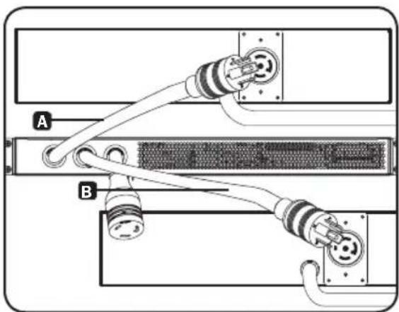
natural_image
Diagram of a server rack with two connected cables (labeled A and B) showing internal components and connectors (no text or symbols present)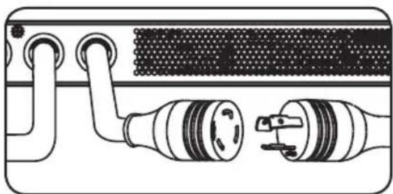
natural_image
Diagram of a device showing two connected components with no visible text or symbols2. Instalación
text_image
Source Status A Source B Preferred Available In Use
LED Encendido

LED Apagado

text_image
Source Status A Source B ● Preferred ○ ○ Available ○ ● In Use ○text_image
Source Status A Source B Preferred Available In Usetext_image
Source Status A Source Preferred Available In Use Btext_image
Essential Status A Source Preferred Available In Use 13.2 A VAV V Hz PF A - VASING A - SOURCE B C - OUTPUT CIRCUIT E - TEMPERATURE [Ω] MODE Volts Source Status A Source Preferred Available In Use 208 A VAV V Hz PF A - SOURCE A - SOURCE B C - OUTPUT CIRCUIT E - TEMPERATURE [Ω] MODE Hz Source Status A Source Preferred Available In Use 60 A VAV V Hz PF A - SOURCE A - SOURCE B C - OUTPUT CIRCUIT E - TEMPERATURE [Ω] MODE MODEtext_image
Corriente Source States A ○ ○ Available In Use 13.2 A LW V Hz 4# PF b A - SOURCE A B - SOURCE B C - OUTPUT CIRCUIT D - TEMPERATURE [Ω] MODE Volts Source States A ○ ○ Preferred Available In Use 208 A LW V Hz 4# PF b A - SOURCE A B - SOURCE B C - OUTPUT CIRCUIT D - TEMPERATURE [Ω] MODE Hz Source States A ○ ○ Preferred Available In Use 60 A LW V Hz 4# PF b A - SOURCE A B - SOURCE B C - OUTPUT CIRCUIT D - TEMPERATURE [Ω] MODE MODECircuito de Carga de Salida
text_image
Corriente del Circuito Source Status A Source Preferred Available In Use 13.2 A VW V Hz PF MODE A - MODE A B - MODE B C - OUTPUT CIRCUIT D - TEMPERATURE [µV] Kilowatts Source Status A Source Preferred Available In Use 4.85 A VW V Hz PF MODE A - MODE A B - MODE B C - OUTPUT CIRCUIT D - TEMPERATURE [µV] Kilowattstext_image
Source Status A Source B Preferred Available In Use 25 A B C D E F H I J K L M N O P Q R S T U V W X Y Z A - MODELS B - MODELS C - OUTPUT ECONUT D - TEMPERATURE (F.M.) E - MODEtext_image
Source Status A Preferred Available In Use IP A LOW V I-HX PP MODE A - SOURCE A B - SOURCE B C - CORNER CHART D - TEMPERATURE (KJ/T)text_image
Source States A Preferred Available In Use C - F A LOW V Hz PF F A - RUMS A 1 - SQUES B 2 - INPUT CIRCUIT 1 - TIMPRESOUR [C,M] MODE 2 Segundos○←↓ Source States A Preferred Available In Use C - F A LOW V Hz PF F A - RUMS A 1 - SQUES B 2 - INPUT CIRCUIT 1 - TIMPRESOUR [C,M] MODE ○ MODEtext_image
Source Status A Source B Preferred Available In UseFuente Preferida (A) Activa
text_image
Source Status A Source B Preferred Available In UseFuente Alterna (B) Activa
7. Servicio
1111 W. 35th Street, Chicago, IL 60609 EE UU • www.tripplite.com/support
Manufacturing Excellence.
1111 W. 35th Street, Chicago, IL USA 60609 • www.tripplite.com/support
natural_image
Diagram showing two parallel metal strips with arrows indicating direction, no text or symbols presentnatural_image
Technical diagram showing alignment of mechanical components with dashed lines and a magnified inset (no text or symbols)2. Installation
natural_image
Technical diagram showing structural components with arrows and a magnified inset of a building detail (no text or symbols)natural_image
Technical diagram showing structural components with an inset magnified view of a detail (no text or symbols present)natural_image
Technical diagram of a mechanical assembly with no visible text or symbolsnatural_image
Technical diagram of a mechanical assembly with an inset showing a close-up of a component (no text or symbols present)natural_image
Technical line drawing of a mechanical assembly with vertical bars and a central component (no text or symbols)2. Installation
natural_image
Technical diagram showing a mechanical assembly with an inset close-up of a component detail (no text or symbols present)natural_image
Technical diagram of a mechanical assembly with an inset showing a close-up of a bracket and bolts (no text or symbols present)natural_image
Diagram of a network device showing two connected cables (labeled A and B) with connectors, no text or symbols present.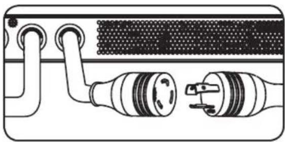
natural_image
Diagram of a device showing two connected components with no visible text or symbols2. Installation
text_image
Source Status A Source B Preferred Available In Use
Voyant à DEL allumé

Voyant à DEL éteint
text_image
Source Status A Source B Preferred Available In Use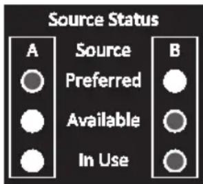
text_image
Source Status A Source B Preferred Available In Usetext_image
Source Status A Source B Preferred Available In Usetext_image
Essential Status A Source Preferred Available In Use 13.2 A VW V Hz PF A - VARG A - SOURCE B C - OUTPUT CIRCUIT E - TEMPERATURE [μF] MODE volts Source Status A Source Preferred Available In Use 208 A VW V Hz PF A - SOURCE A - SOURCE B C - OUTPUT CIRCUIT E - TEMPERATURE [μF] MODE Hz Source Status A Source Preferred Available In Use 60 A VW V Hz PF A - SOURCE A - SOURCE B C - OUTPUT CIRCUIT E - TEMPERATURE [μF] MODE MODEtext_image
Source Status A Source B Preferred Available In Use t S t A kW V Hz FP MODE 2 seconds Source Status A Source B Preferred Available In Use 8.8.8. A kW V Hz FP MODE 88 A kW V C -OUTRICHROOM T -TEMPORATE (GPa) MODE MODEtext_image
Source Status A Source B Preferred Available In UseSource principale (A) active
text_image
Source Status A Source B Preferred Available In UseSource alternative (B) active
7. Entretien
1111 W. 35th Street, Chicago, IL 60609 USA • www.tripplite.com/support
Manufacturing Excellence.
1111 W. 35th Street, Chicago, IL 60609 USA • www.tripplite.com/support
natural_image
Diagram showing two parallel metal strips with arrows indicating direction, no text or symbols presentnatural_image
Technical diagram showing mechanical assembly with alignment guides and a magnified inset of a component detail (no text or symbols)2. Установка
natural_image
Technical diagram showing structural components with an inset magnified view of a building facade detail (no text or symbols)natural_image
Technical diagram showing structural components with an inset magnified view of a mechanical assembly (no text or symbols)natural_image
Technical diagram of a mechanical assembly with no visible text or symbolsnatural_image
Technical diagram of a mechanical assembly with an inset showing a close-up of a component (no text or symbols present)natural_image
Technical line drawing of a mechanical assembly with vertical supports and a central component (no text or symbols)2. Установка
natural_image
Technical diagram showing a mechanical assembly with an inset close-up of a component detail (no text or symbols present)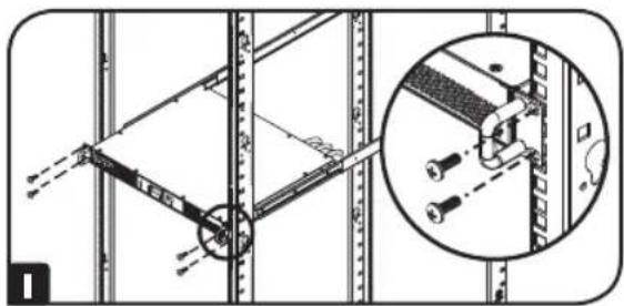
natural_image
Technical diagram of a mechanical assembly with a magnified inset showing a bracket detail (no text or symbols)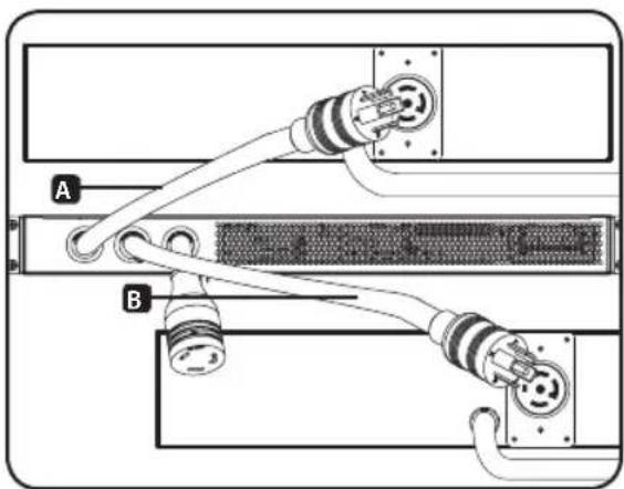
natural_image
Diagram of a server rack with two connectors labeled A and B, showing internal wiring and socket connections (no text or symbols beyond labels)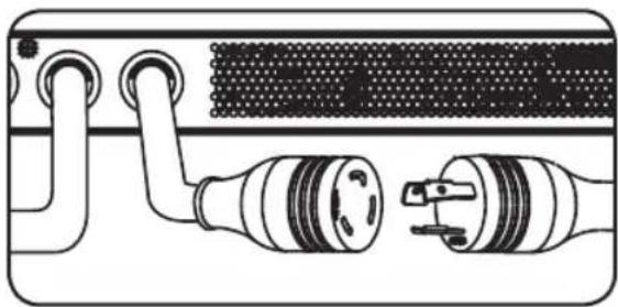
natural_image
Diagram of a device with two connected components, one showing internal wiring and the other showing plug connections (no text or symbols)2. Установка
text_image
Source Status A Source B Preferred Available In Use 1 2.5 8.8.8 A kW V Hz PF 4 8.8 A - SOURCE A b - SOURCE B C - OUTPUT CIRCUIT t - TEMPERATURE (C/F) MODE 3text_image
Source Status A Source B Preferred Available In Use
Горящий СИД

Негорящий СИД
text_image
Source Status A Source B ● Preferred ○ ○ Available ○ ● In Use ○text_image
Source Status A Source B Preferred Available In Usetext_image
Source Status A Source Preferred Available In Use Btext_image
Source Status A Preferred Available In Use C - F A LOW V Hz PF F A - MODELA E - TAOKB B E - OUTPUT SICUT E - TEMPERATURE [J/V] MODE
text_image
Source Status A Preferred Available In Use C - F A VSW V Hz PF C A - VSWING A B - VOUTRUN B C - OUTPUT Schematic D - TEMPERATURE [F/M] MODEtext_image
Source Status A Preferred Available In Use PSS A LOW V Hz PF b A-0.0256 A B-0.0256 B C-OUTPUT CIRCUY D-TEMPORARY (CF) MODE
text_image
Source Status A Sources Preferred Available In Use SCR A LAM V Hz PF 9 A - SOURS A B - NUMBER B C - OUTPUT SIGHT D - MULTIPROCCUR (DC) MODE
text_image
Source Status A Preferred Available In Use SCR A V H2 PF MODE A-00000 A 1-00000 B C-OUTPUT CIRCUIT 1-00000000000000000000000000000000000000000000000000000000000000000000000000000
text_image
Source Status A Source B Preferred Available In Usetext_image
Source Status A Source B Preferred Available In Use1111 W. 35th Street, Chicago, IL 60609 USA • www.tripplite.com/support