
System 15 - Synthesizer BEHRINGER - Free user manual and instructions
Find the device manual for free System 15 BEHRINGER in PDF.
| Brand | Behringer |
| Model | System 15 |
| Product type | Analog modular synthesizer |
| Power supply | 100-240 V AC, 50/60 Hz |
| Power consumption | 20 W (estimated) |
| Dimensions (W x D x H) | 482 x 177 x 89 mm (3U) |
| Weight | 8 kg (estimated) |
| Main features | Analog subtractive synthesis, VCO oscillators, VCF filter, ADSR envelopes, VCA, LFO modulator, audio and CV outputs |
| Included modules | 921 oscillators, 904 filter, 911 envelope, 902 VCA, CP3A mixer, etc. |
| Connectivity | 6.35 mm jack inputs/outputs, MIDI In/Out, power supply |
| Operating temperature | 5°C to 45°C |
| Maintenance and cleaning | Clean with a dry cloth only |
| Safety | Do not open the device, leave repairs to a professional |
| Spare parts and repairability | No user-serviceable parts |
| Included accessories | Power cable (not specified) |
| General information | Clone of the Moog System 15, Eurorack compatible |
Frequently Asked Questions - System 15 BEHRINGER
User questions about System 15 BEHRINGER
0 question about this device. Answer the ones you know or ask your own.
Ask a new question about this device
Download the instructions for your Synthesizer in PDF format for free! Find your manual System 15 - BEHRINGER and take your electronic device back in hand. On this page are published all the documents necessary for the use of your device. System 15 by BEHRINGER.
USER MANUAL System 15 BEHRINGER
SYSTEM 15
Complete "System 15" Modular Synthesizer with 16 Modules, MIDI-to-CV Converter and EURORACK GO case
2 SYSTEM 15 Quick Start Guide-3
EN
ES
FR
Important Safety Instructions
Terminals marked with this symbol carry electrical current of sufficient magnitude to contribute risk of electric shock. Use only high-quality professional speaker cables with V^* TS or twist-locking plugs pre installed. All other installation or modification should be performed only by qualified personnel.
This symbol, wherever it appears, alerts you to the presence of uninsulated dangerous voltage inside the enclosure - voltage that may be sufficient to constitute a risk of shock.
This symbol, wherever it appears, alerts you to important operating and maintenance instructions in the accompanying literature. Please read the manual.
Caution To reduce the risk of electric shock, do not remove the top cover (or the rear section). No user serviceable parts inside. Refer servicing to qualified personnel.
Caution To reduce the risk of fire or electric shock, do not expose this appliance to rain and moisture. The apparatus shall not be exposed to dripping or splashing liquids and no objects filled with liquids, such as vases, shall be placed on the apparatus.
Caution These service instructions are for use by qualified service personnel only. To reduce the risk of electric shock do not perform any servicing other than that contained in the operation instructions. Repairs have to be performed by qualified service personnel.
Warning Please refer to the information on the exterior of bottom enclosure for electrical and safety information before installing or operating the desire.
- Please read and follow all instructions and warnings.
-
Keep the apparatus away from water (except for outdoor products).
-
Clean only with dry dots.
-
Do not block ventilation openings. Do not install in a confined space. Install only according to manufacturer's instructions.
-
Protect the power cord from damage, particularly at plugs and appliance socket.
-
Do not install near any heat sources such as radiators, heat registers, stoves or other apparatus (including amplifiers) that produce heat.
-
Do not defeat the safety purpose of the polarized or grounding-type plug. A polarized plug has two blades with one wider than the other (only for USA and Canada). A grounding-type plug has two blades and a third grounding piping. The wide blade or the third piping are provided for your safety. If the provided plug does not fit into your outlet, consult an electrician for replacement of the obsolete outlet.
-
Protect the power cord from damage, particularly at plugs and appliance socket.
-
Use only attachments and accessories recommended by the manufacturer.

- Use only specified cars, stands, tripods, brackets, or tables. Use caution to prevent tip mesh when mixing the cars' apparatus combination.
- Unplug during storms, or if not in use for
along period.
-
Only use qualified personnel for servicing, especially after damage.
-
The apparatus with protective earthing terminal shall be connected to a MING socket outlet with a protective earthing connection.
-
Where the MAINS plug or an appliance coupler is used as the disconnect device, the disconnect device shall remain readily operable.
-
Avoid installing in confined spines like bootcasses.
-
Do not place naked flame sources, such as lighted candles, on the apparatus.
-
Operating temperature range 5° to 45°C (41° to 113°F).
LEGAL DISCLAIMER
Music Tribe accepts no liability for any loss which may be suffered by any person who relies either wholly or in part upon any description, photograph, or statement contained herein. Technical specifications, appearances and other information are subject to change without notice. All trademarks are the property of their respective owners, Mids, Kark Teknik, Lab Gruppen, Laiz, Janney, Turbosound, TC Electronic, TC Holloon, Büchinger, Bugara, Aston Microphones and Coolaudio are trademarks or registered trademarks of Music Tribe Global Branch Ltd. © Music Tribe Global Branch Ltd. 2024 All rights reserved.
LIMITED WARRANTY
For the applicable warranty terms and conditions and additional information regarding Music Tribe's Limited Warranty, please see complete details online at community.musictribe.com/support.

combination charlscapparell.
BESCHRÄNKTE GARANTIE
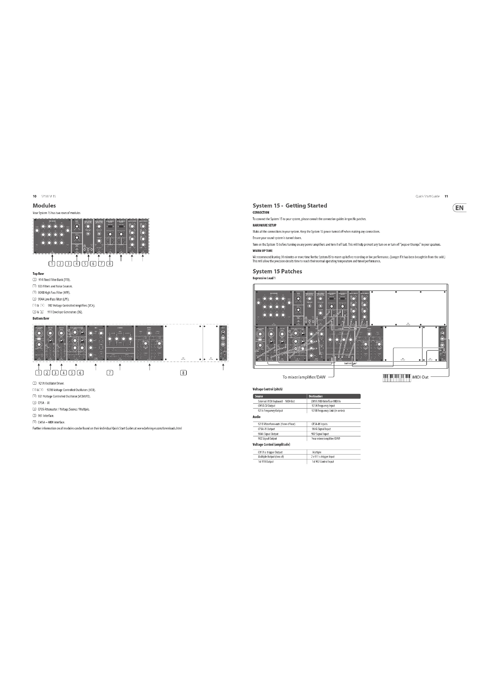
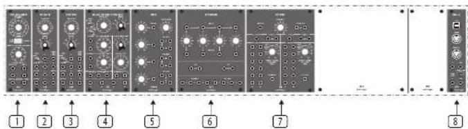
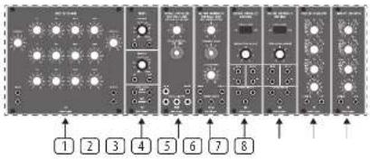
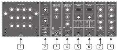
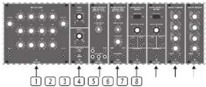
Your System 15 has two rows of modules

Top Row
① 914 Fixed Filter Bank (FFB).
[2] 923 Filters and Noise Sources.
904B High Pass Filter (HPF).
9046 Low Pass Filter (LEF).
902 Voltage Controlled Amplifiers (VCA).
1 & 3 911 Envelope Generators (EG).
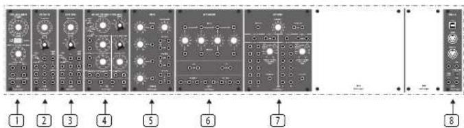
Bottom Row
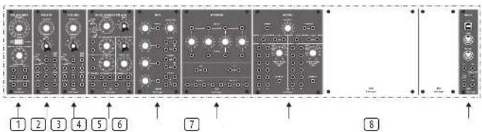
① 921A Oscillator Driver.
\$218 Voltage Controlled Oscillators (VCO).
921 Voltage Controlled Oscillator (VCO/LFO).
CP3A-M
⑥ CP35 Attenuator / Voltage Source / Multiple.
961 Interface.
CMTA - MIDI interface
Further information on all modules can be found on their individual Quick Start Guides at www.behringer.com/downloads.html
Quick Star Guide
System 15 - Getting Started
CONNECTION
To connect the System 15 to your system, please consult the connection guides in specific patches.
HARDWARE SETUP
Make all the connections in your system. Keep the System 75 power turned off when making any connections.
Ensure your sound system is turned down.
Turn on the System 15 before turning on any power amplifiers and turn it off last. This will help prevent any turn on or turn off "pops or thumps" in your speakers.
WARM UP TIME
We recommend leaving 30 minutes or more time for the System 15 to warm up before recording or live performance. (Longer if it has been brought in from the cold.) This will allow the precision circuits time to reach their normal operating temperature and tuned performance.
System 15 Patches
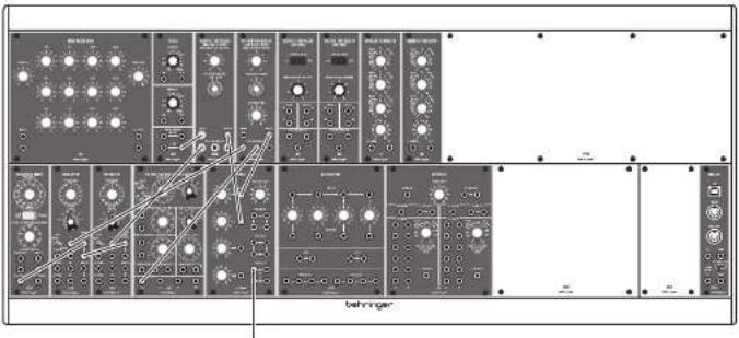
Expressive Lead 1
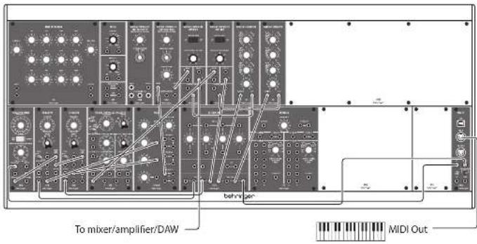
Voltage Control (pitch)
| Source | Destination |
| External MDD Keyboard - MDD Out | CM14 MDD Interface MDD in |
| CM14 CY Output | 921A Frequency Input |
| 921A Frequency Output | 921B Frequency Link (in series) |
Audio
| 9218 Waveform cuts (three of four) | CP3A-M Inputs |
| CP3A-M Output | 5014 Signal Input |
| 5046 Signal Output | 502 Signal Input |
| 502 Signal Output | Your mixer,Sampler,DAM |
Voltage Control (amplitude)
| CM14 s-trigger Output | Multiple |
| Multiple Output (Two off) | 2 x 971 s-trigger input |
| 1st 911 Output | 1st 902 Control Input |
Voltage Control (modulation)
| 921 Max Sine Output 2nd 902 Signal Input | |
| 2nd 902 Signal Output 9218 DC Bus Inputs via Multiple | |
| 2nd 911 Output 2nd 902 Control Input | |
This patch allows a delayed vibrato effect to fade in when a note is held.
The external keyboard controls the pitch and triggering of notes via the CMTA MIDI Interface. As this can be switched between v-trigger and s-trigger then s-trigger should be selected and the 961 Interface need not be used.
Pitch CV is fed to one of the 921As, which daisy chain to the 921B VCOs. The selected waveform from each oscillator is fed to the CP3A-M mixer, which then feeds the 904A IPF. S-triggers are fed to a multiple, and then to the 911s' s-trigger inputs.
The output of the 904A LPF is fed to one of the 902 VCA, which feeds out to your mixer, amplifier or DAW. This VCA is controlled by the first 911 EG. The second 911 EG controls the second 902 VCA.
The second 902 VCA signal input is fed from the 9211FC. Its output is fed to one of the CP35 multiples, whose outputs feed the DC Modulation inputs of the 9218 VCOs. The second 911 should have a long attack time and full sustain.
So long as the first 911 has a long sustain time, when a note is held a vibrato effect will fade in slowly. When notes are played legato there is little or no vibrato
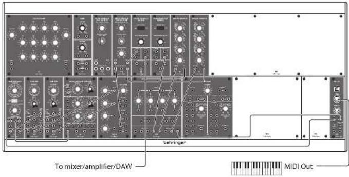
Space Rock
To mixer/amplifier/DAW
This patch creates two of the classic 'space rock' sounds, and allows them to be mixed together.
| Source Destination | |
| 921 Sine Wave Output 3046 Control Input | |
| 921A Frequency Output 2x 921B Frequency Link In series) | |
| 1st 921B Sine Wave Output 9040 Control Input | |
| 2nd 921B Sine Wave Output 9048 Control Input | |
| 923 Peak Signal Output 3048 Signal Input | |
| 954X Signal Output CP2A M Input 1 | |
| 954S Signal Output CP2A-M Input 2 | |
| CP2A-M Output | Your mine, amplifier, DAW |
Control settings are very important for this patch.
Regeneration on the 901A must be set to 9 or 10 to force the filter to self-oscillate. The 921A should have Octave selected and the frequency control set to -6
The 921Bs should be set to "Lo" - these oscillators provide the sweep to the filters
The 921 should be set to 'Sub' — this is the main modulation for the self-oscillating filter, and manual alteration of the Frequency control helps to produce the classic sound.
The pink noise feeding the 904B produces a swept wind effect, that can be altered with the Fixed Control Voltage Altering the Fixed Control Voltage of the 904A also produces interesting effects
The CP3A-M balances the two signals, as an alternative feed the outputs of the two filters direct to two mixer or amplifier channels. Both sounds benefit from a lot of effect
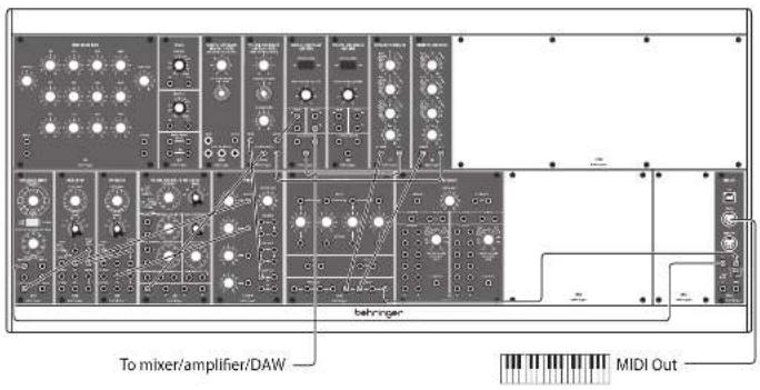
Expressive Lead #2
This sound uses Pulse Width Modulation to a pair of oscillators, one of which should be slightly detuned to fatten the sound.
Voltage Control (pitch)
| Source Destination | |
| External MIDI Keyboard – MIDI Out | QM14 MIDI Interface MIDI in |
| 9214 Frequency Output 9218 Oscillator Frequency Link (in series) | |
| 921A Width Output | 921B Oscillator Width Link (in series) |
Audio
| 2 x 9218 Square Wave Output | CP3A-M Inputs 1 & 2 |
| CP3AM Output | 904A Signal Input |
| 904A Signal Output 902 Signal Input | |
| 902 Signal Output | Your Mixer/Amplifier/DAY |
Voltage Control (Amplitude)
| EMTA s-trigger Output via Multiple | 2 x 9'11 s-trigger Input |
| 1st 9'11 Output | 1st 502 Control Input |
Voltage Control (Modulation)
| 921 sine wave Output | 921A Width Input |
| 921A Width Link | 2 x 921B Width Link (in series) |
| 2nd 911 | 904A Control Input |
The dashed 9318 ADCs give a fat sound, whose timbe changes constantly at the speed of the 931 sine wave—the 931 should be in Sub mode, speed can be adjusted to suit. The sound comes from the 904A LPE, whose Fixed Control Voltage and Regeneration can be set to whatever suits your aim, plus modulation from the second 911 EG, EG settings can be adjusted to suit for the main part of the sound, although medium to high levels on T2 (decay), T3 (release) and E sustain) are recommended. The second EG should have a medium length T1 (attack), medium T2 (decay) and minimal T3 (release) and E sustain).
Percussive Lead
A simple, two oscillator lead sound with a hard front end and timbral development which is also suitable for meiotic sequencing.
Voltage Control (pitch)
| Source Destination |
| External MIBI Keyboard - MIBI Out US14 MIBI Interface MIO in |
| CM1A CV Out via Multiple 921A Frequency Input |
| 921A Frequency Output 921B Frequency Link (in series) |
| Audio |
| 1st 921B Triangle wave Output CP34-80 mixer Input 1 |
| 2nd 921B Smartooth wave Output CP34-M mixer Input 2 |
| CP34, 80 Input 904A Signal input |
| 951A Signal Output 902 VCA |
| 902 Signal Output Your MHz/Amplifier/DWG |
Voltage Control (Amplitude)
| CM1A s-trigger out via Multiple 2 x 9'11 s-trigger Input | |
| 1st 9'11 Output 902 Control input | |
| Voltage Control (Modulation) | |
| 921 Sine Wave Out | 904A Control input |
| 2nd 9'11 Output | 904A Control input |
This sound uses two 921B VCOs, with different waveforms, and sounds best if one is slightly detuned. They both feed the 904A LPF, and their relative levels can be adjusted with the CP34-M mixer as required. The 904A's output is fed to a 902 VCA, whose amplitude is controlled by the 1st 911 EG
To obtain the percussive edge the 911's settings should be T1 (attack) 2ms. T2 (decay) 200ms. T3 (release) 200ms, E sus(tain) 4 seconds
The 9048 is modulated by a slow sine wave from the 921 LTO and by the 2nd 911 EG, which should have settings around T1 (attack) 1 second, T2 (decay) 50ms, T3 (release) 4 seconds, E sustain) 9
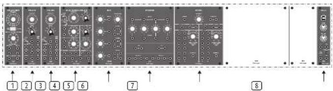
Quick Star Guide
Modules
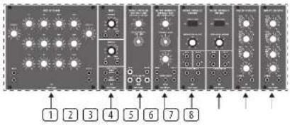
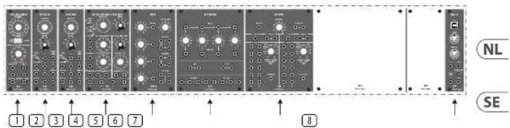
Your System 15 has two rows of modules

Top Row
914 Fixed Filter Bank [FFB].
(2) 923 Filters and Noise Sources.
9048 High Pass Filter (HPF).
④ 904A Low Pass Filter [LPE].
5 & 6 902 Voltage Controlled Amplifiers (VCA).
7 & 8 911 Envelope Generators (EG)
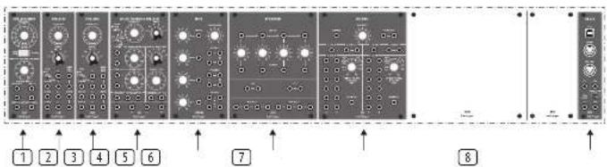
Bottom Row
① 921A Oscillator Driver
923B Voltage Controlled Oscillators (VCO)
4 921 Voltage Controlled Oscillator (VCO/LFO)
① CP3A-M
⑤ OP35 Attenuator / Voltage Source / Multiple.
961 Interface.
① DATA - MID interface
Further information on all modules can be found on their individual Quick Start Guides at www.behringer.com/downloads.html
To mixer/amplifier/DAW
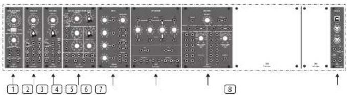
Your System 15 has two rows of modules
Top Row
① 914 Fixed Filter Bank (FFB).
[2] 923 Filters and Noise Sources.
904B High Pass Filter (HPF).
9046 Low Pass Filter (LEF).
902 Voltage Controlled Amplifiers (VCA).
☐ & ☐ 911 Envelope Generators [EG].
Bottom Row
① 921A Oscillator Driver.
\$218 Voltage Controlled Oscillators (VCO).
921 Voltage Controlled Oscillator (VCO/LFO).
CP3A-M
⑥ CP35 Attenuator / Voltage Source / Multiple.
961 Interface.
CMTA - MIDI interface
Further information on all modules can be found on their individual Quick Start Guides at www.behringer.com/downloads.html
Quick Star Guide
21
System 15 - Mise en oeuvre
CONNEXION
| Source | Destination |
| Cluster MIDI extreme - some MIDI MIDI interface MIDI - entries MIDI IN | |
| MIDI A some CV | 921A Entries Frequency |
| 921A Sortie Control Outputs to 921B | 921B entries 921AB Link Freq (on series) |
Audio
Voltage Control (modulation)
Your System 15 has two rows of modules.

Top Row
① 914 Fixed Filter Bank (FFB).
(2) 923 Filters and Noise Sources.
9048 High Pass Filter (HPF).
④ 904A Low Pass Filter [LPE].
5 & 6 902 Voltage Controlled Amplifiers (VCA).
7 & 8 911 Envelope Generators (EG).
Bottom Row
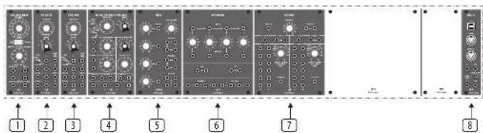
① 921A Oscillator Driver
923B Voltage Controlled Oscillators (VCO)
4 921 Voltage Controlled Oscillator (VCO/LFO)
① CP3A-M
6 CP35 Attenuator / Voltage Source / Multiple.
961 Interface.
① DATA - MIDI interface.
Further information on all modules can be found on their individual Quick Start Guides at www.behringer.com/downloads.html
To mixer/amplifier/DAW
| Source | Destination |
| Externals MIDI Keyboard – MIDI Out CMTA MIDI Interface MIDI In | |
| CMTA CV Ausgang via Multiple | 9214 Frequency-Engang |
| 9214 Frequency Ausgang 9218 Frequency Link (in Series) | |
Audio
Your System 15 has two rows of modules

Top Row
① 914 Fixed Filter Bank (FFB).
[2] 923 Filters and Noise Sources.
904B High Pass Filter (HPF).
9046 Low Pass Filter (LEF).
902 Voltage Controlled Amplifiers (VCA).
1 & 2 911 Envelope Generators [EG].
Bottom Row
① 921A Oscillator Driver.
\$218 Voltage Controlled Oscillators (VCO).
921 Voltage Controlled Oscillator (VCO/LFO).
CP3A-M
⑥ CP35 Attenuator / Voltage Source / Multiple.
961 Interface.
CMI4 - MIDI interface
Further information on all modules can be found on their individual Quick Start Guides at www.behringer.com/downloads.html
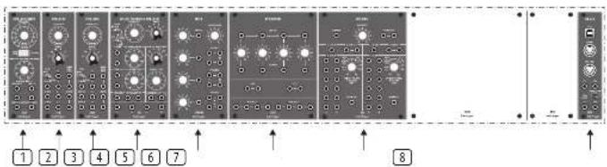
Your System 15 has two rows of modules
Top Row
914 Fixed Filter Bank [FFB].
[2] 923 Filters and Noise Sources.
9048 Linh Pass Filter (HPF).
④ 904A Low Pass Filter [LPF].
902 Voltage Controlled Amplifiers (VCA).
7 & 8 911 Envelope Generators (EG)
Bottom Row
① 921A Oscillator Driver
923B Voltage Controlled Oscillators (VCO)
4 921 Voltage Controlled Oscillator (VCO/LFO)
① CP3A-M
⑤ OP35 Attenuator / Voltage Source / Multiple.
961 Interface.
① DATA - MID interface
Further information on all modules can be found on their individual Quick Start Guides at www.behringer.com/downloads.html
To mixer/amplifier/DAW
Voltage Control (pitch)
Your System 15 has two rows of modules
Top Row
① 914 Fixed Filter Bank (FFB).
[2] 923 Filters and Noise Sources.
904B High Pass Filter (HPF).
9046 Low Pass Filter (LEF).
902 Voltage Controlled Amplifiers (VCA).
☐ & ☐ 911 Envelope Generators [EG].
Bottom Row
① 921A Oscillator Driver.
\$218 Voltage Controlled Oscillators (VCO).
921 Voltage Controlled Oscillator (VCO/LFO).
CP3A-M
⑥ CP35 Attenuator / Voltage Source / Multiple.
961 Interface.
CMTA - MIDI interface
Further information on all modules can be found on their individual Quick Start Guides at www.behringer.com/downloads.html
Stuurspanning (Voltage Control) (toonhoogte)
| Bron | Doel |
| Outer MIOX keyboard - MIDI Out, CM1A MIOX interface MID In | |
| CM1A CV-ümgang | 921A frequentile-ingang |
| 921A frequenite-uitwor | 921B frequenite-koppeeling (in series) |
Audio
| 9218 Gohvormuitgangen (die van werk) | CP34-M Ingangen |
| CP34-Mütigung | 904 M Sinaaalingang [SIG IN] |
| 504 A. Sinaaalingang [SIG IN] | 902 Sinaaalingang [SIG IN] |
| 502 Sinaaalingang [SIG OUT] | Uw mixer/Aversterker/DKN |
Stuurspanning (Voltage Control) (amplitude)
| CM14 - S-triggeringang (activering) | Multiple |
| Multiple utgang (cwe van) | 2 x 911 S-triggeringang [S. THIGIN] |
| 1e 911 Utgang [OJI] | 1e 902 Bestuningsgang [CUH IROL INPUT] |
Stuurspanning (Voltage Control) (modulatie)
921 Aux Sinusuitgang 2e 902 Signezingang [SIG IN]
2e 902 Signaaltgang (SIG DU 921B DC-modulatie) in-sangen via Multiple
2e 911 Umgang [CUT] 2e 902 Besturingsingang [CONTROL INPUT]
Voltage Control (pitch)
| Bron | Doel |
| External KIDI-Isotserbord - MDX-Uitgang | CMT4 KIDI-interface MDX-invoer |
| CMT4 CV-Uitgang via Mondeere | 921A frequentie-ingang |
| 921A Frequentie Uitover | 921B frequentieverbinding (in serie) |
Audio
| 1c 921B Dincheloogdutvoer | CP34-M mixer Ingang 1 |
| 2e 921B Zuglandgellutvoer | CP34-M mixer Ingang 2 |
| CP34, M mixer | 9044 Signal Ingang |
| 9044 Signalutvoer | 502 VCA |
| 902 Signalutvoer | Uw Meier/Verstehler/DAN |
Stuurspanning (Voltage Control) (amplitude)
| CM1A s-trapeurant via meordere | 2 x 911 s-trapein-ingang |
| 1x 911 Illister | 902 Control-ingang |
| Stuurspanning (Voltage Control) (modulatie) | |
| 921 Sinaspoffatuvor | 9046 Control-ingang |
| 2x 911 Illister | 9048 Control-ingang |
Your System 15 has two rows of modules
Top Row
① 914 Fixed Filter Rank (FFB).
(2) 923 Filters and Noise Sources.
① 9048 High Pass Filter (HPE).
④ 904A Low Pass Filter (LPF).
5 & 902 Voltage Controlled Amplifiers (VCA).
2 & 3 911 Envelope Generators (EG).
Bottom Row
① 921A Oscillator Driver.
2 & 3 921B Voltage Controlled Oscillators (VCO).
4 921 Voltage Controlled Oscillator (VCO/LF0).
CP3A-M
⑥ CP35 Attenuator / Voltage Source / Multiple.
961 Interface
① CMA - MID interface.
Further information on all modules can be found on their individual Quick Start Guides at www.behringer.com/downloads.html
To mixer/amplifier/DAW
Your System 15 has two rows of modules

Top Row
① 914 Fixed Filter Bank (FFB).
[2] 923 Filters and Noise Sources.
904B High Pass Filter (HPF).
9046 Low Pass Filter (LEF).
5 & 6 902 Voltage Controlled Amplifiers (VCA).
1 & 2 911 Envelope Generators [EG].
Bottom Row
① 921A Oscillator Driver.
2 A 9218 Voltage Controlled Oscillators (VDD).
921 Voltage Controlled Oscillator (VCO/LFO).
CP3A-M
⑥ CP35 Attenuator / Voltage Source / Multiple.
961 Interface.
CM14 - MIDI interface
Further information on all modules can be found on their individual Quick Start Guides at www.behringer.com/downloads.html
Quick Star Guide
51
① 9214 オシレータードライバ。
To mixer/amplifier/DAW
Other important information

Important information

Informations importantes

Responsible Party Name: Music Tribe Commercial NV Inc. Address: 122 E. 42nd St.1,
8th Floor NY, NY 10168, United States
Email Address: legal@musictribe.com
SYSTEM 15
This equipment has been tested and found to comply with the limits for a Class B digital device, pursuant to part 15 of the FCC Rules. These limits are designed to provide reasonable protection against harmful interference in a residential installation. This equipment generates, uses and can radiate radio frequency energy and, if not installed and used in accordance with the instructions, may cause harmful interference to radio communications. However, there is no guarantee that interference will not occur in a particular installation. If this equipment does cause harmful interference to radio or television reception, which can be determined by turning the equipment off and on, the user is encouraged to try to correct the interference by one or more of the following measures:
- Reorient or relocate the receiving antenna.
- Increase the separation between the equipment and receiver.
- Connect the equipment into an outlet on a circuit different from that to which the receiver is connected.
- Consult the dealer or an experienced radio/TV technician for help.
This equipment complies with Part 15 of the FCC rules. Operation is subject to the following two conditions:
(1) this device may not cause harmful interference, and (2) this device must accept any interference received, including interference that may cause undesired operation.
Important information:
Changes or modifications to the equipment not expressly approved by Music Tribe can void the user's authority to use the equipment.
CE
Hereby, Music Tribe declares that this product is in compliance with Directive 2014/35/EU, Directive 2014/30/EU, Directive 2011/65/EU and Amendment 2015/863/EU, Directive 2012/19/EU, Regulation 519/2012 REACH SVHC and Directive 1907/2006/ECC.
Full text of EU DoC is available at https://community.musictribe.com/
EU Representative: Music Tribe Brands DK A/S
Address: Gammel Strand 41, DK-1202 Røbenhavn K, Denmark
UK Representative: Music Tribe Brands UK Ltd.
Address: 8 ^th Floor, 20 Farrington Street London EC44 44B, United Kingdom

Correct disposal of this product: This symbol indicates that this product must not be disposed of with household waste, according to the WEEE Directive
(2012/15/04) and your national law. This product should be taken to a collection center licensed for the recycling of waste electrical and electronic
epartment (see). The first authoring of a type of mobile database is possible negative impact on the environment and human health due to potentially hazardous
substances that are generally associated with FEE. At the same time, your cooperation in
the correct disposal of this product will contribute to the efficient use of natural resources.
For more information about where you can take your waste equipment for recycling, please contact your local city office, or your household waste collection service.
- SYSTEM 15
- LEGAL DISCLAIMER
- LIMITED WARRANTY
- BESCHRÄNKTE GARANTIE
- Top Row
- System 15 - Getting Started
- CONNECTION
- HARDWARE SETUP
- WARM UP TIME
- System 15 Patches
- Modules
- System 15 - Mise en oeuvre
- CONNEXION
- Voltage Control (modulation)
- Stuurspanning (Voltage Control) (modulatie)
- Other important information
- Important information
- Informations importantes
- CE
Brand : BEHRINGER
Model : System 15
Category : Synthesizer