SmartOnline SUINT3000LCD2U - Inverter Tripp Lite - Free user manual and instructions
Find the device manual for free SmartOnline SUINT3000LCD2U Tripp Lite in PDF.
User questions about SmartOnline SUINT3000LCD2U Tripp Lite
0 question about this device. Answer the ones you know or ask your own.
Ask a new question about this device
Download the instructions for your Inverter in PDF format for free! Find your manual SmartOnline SUINT3000LCD2U - Tripp Lite and take your electronic device back in hand. On this page are published all the documents necessary for the use of your device. SmartOnline SUINT3000LCD2U by Tripp Lite.
USER MANUAL SmartOnline SUINT3000LCD2U Tripp Lite
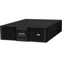
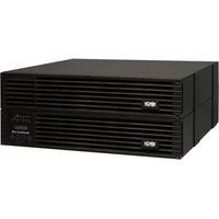
Single-Phase Rackmount Online UPS Systems with Built-in LCD Monitoring & Control Screen
Not suitable for mobile applications.
SUINT1000LCD2U
(Series Number: AGPS8294)
SUINT1500LCD2U
(Series Number: AGPS8295)
SUINT2200LCD2U
(Series Number: AGPS7958)
SUINT3000LCD2U
(Series Number: AGPS7959)
SU3000LCD2UHV
(Series Number: AGPS8296)
- Overview 2
Parts List 2
Additional Accessory Options 2
Model Specific Accessories 2
-
Important Safety Instructions 2
-
UPS Circuit Block Diagram 3
-
Installation 4
Rack Mounting 4
Tower Mounting 5
Smart Battery Communications 6 Connection
- Basic Connections
and Start-Up
Quick Start Guide

- Features 9
Front Panel Controls, LEDs and 9
LCD Screen
Rear Panel Features 9
- Operations 11
LCD Front-Panel Display and Controls 11
Front Panel Button Functions 12
Home Screen Layout 12
Power Strategy Selection Options 13
Front Panel LCD Selection and 14
Configuration Options
Configuring External Battery Packs 18
-
Optional Connections 20
-
Troubleshooting and Event Log 23
-
Internal Battery Replacement 25
-
Storage and Service 26
-
Product Registration and 27
Regulatory Compliance
Español 28
Français 55
Русский 82
Deutsch 109
NOTE: External battery pack options require configuration using front panel LCD interface or via Tripp Lite's EXTERNAL BATTERY CONFIGURATION software.
WARRANTY REGISTRATION
Register your product today and be automatically entered to win an ISOBAR surge protector in our monthly drawing!
tripplite.com/warranty


text_image
TRIPP·LITE
Manufacturing Excellence.
1111 W. 35th Street, Chicago, IL 60609 USA • tripplite.com/support
Copyright © 2019 Tripp Lite. All rights reserved. SmartOnline® is a trademark of Tripp Lite. For latest updates, please visit tripplite.com
Overview
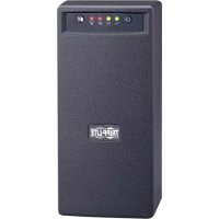
Tripp Lite SmartOnline Rackmount UPS Systems with interactive LCD interface feature online, double-conversion UPS protection with full-time sinewave output and zero transfer time suitable for all advanced networking applications. Each system provides long running battery support with optional extended-run and Web communications ability. Built-in interfaces include USB, RS-232 serial and Emergency Power Off (EPO). The interactive front panel LCD screen provides detailed UPS status, preset and control options. Optional max efficiency and auto-adaptive power strategy options enable high-efficiency operation with reduced power consumption and BTU heat output.
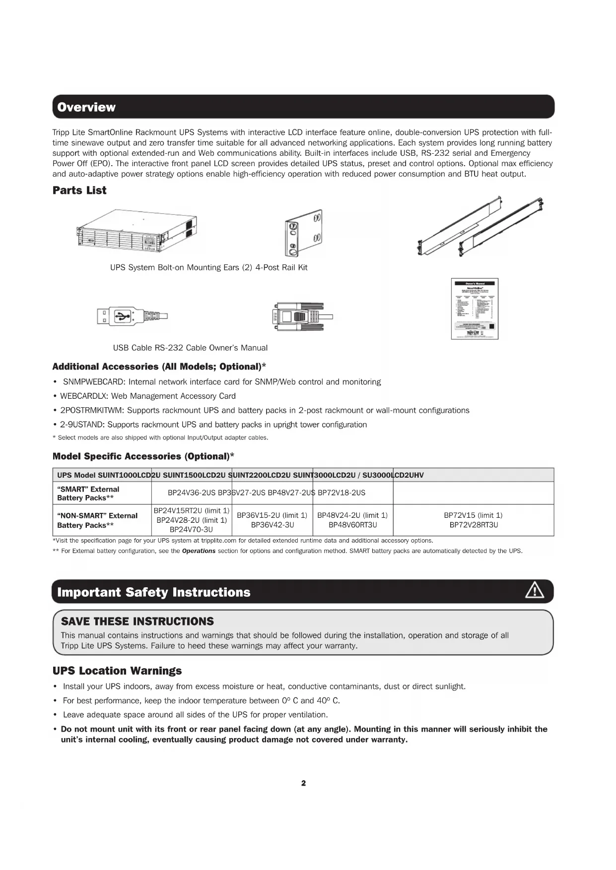
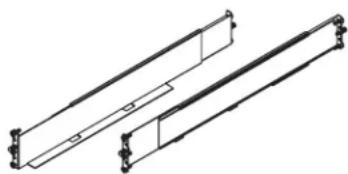
Parts List

natural_image
Line drawing of a server rack unit with multiple drive bays and ventilation grilles (no text or labels)
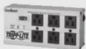
UPS System Bolt-on Mounting Ears (2) 4-Post Rail Kit

natural_image
Technical line drawing of two parallel mechanical components with mounting holes (no text or symbols)
USB Cable RS-232 Cable Owner's Manual
Additional Accessories (All Models; Optional)\*
• SNMPWEBCARD: Internal network interface card for SNMP/Web control and monitoring
• WEBCARDLX: Web Management Accessory Card
- 2POSTRMKITWM: Supports rackmount UPS and battery packs in 2-post rackmount or wall-mount configurations
• 2-9USTAND: Supports rackmount UPS and battery packs in upright tower configuration
* Select models are also shipped with optional Input/Output adapter cables.
Model Specific Accessories (Optional)*
| UPS Model SUINT1000LCD | 2U SUINT1500LCD2U | SUINT2200LCD2U | SUINT3000LCD2U / SU3000LCD2UHV | |
| “SMART” External Battery Packs** | BP24V36-2US BP36V27-2US BP48V27-2US | BP72V18-2US | ||
| “NON-SMART” External Battery Packs** | BP24V15RT2U (limit 1)BP24V28-2U (limit 1)BP24V70-3U | BP36V15-2U (limit 1)BP36V42-3U | BP48V24-2U (limit 1)BP48V60RT3U | BP72V15 (limit 1)BP72V28RT3U |
*Visit the specification page for your UPS system at tripplite.com for detailed extended runtime data and additional accessory options.
** For External battery configuration, see the Operations section for options and configuration method. SMART battery packs are automatically detected by the UPS.
Important Safety Instructions

SAVE THESE INSTRUCTIONS
This manual contains instructions and warnings that should be followed during the installation, operation and storage of all Tripp Lite UPS Systems. Failure to heed these warnings may affect your warranty.
UPS Location Warnings
• Install your UPS indoors, away from excess moisture or heat, conductive contaminants, dust or direct sunlight.
- For best performance, keep the indoor temperature between 0^ C and 40^ C .
- Leave adequate space around all sides of the UPS for proper ventilation.
- Do not mount unit with its front or rear panel facing down (at any angle). Mounting in this manner will seriously inhibit the unit's internal cooling, eventually causing product damage not covered under warranty.
UPS Connection Warnings
- Connect your UPS directly to a properly grounded AC power outlet. Do not plug the UPS into itself; this will damage the UPS.
- Do not modify the UPS's plug, and do not use an adapter that would eliminate the UPS's ground connection.
- Do not use extension cords to connect the UPS to an AC outlet. Your warranty will be voided if anything other than Tripp Lite surge protectors are used to connect your UPS to an outlet.
- If the UPS receives power from a motor-powered AC generator, the generator must provide clean, filtered, computer-grade output.
- The mains socket outlet that supplies the UPS should be near the UPS and be easily accessible.
- To remove AC voltage from the UPS, pull the plug from the socket outlet.
Equipment Connection Warnings
- Use of this equipment in life support applications where failure of this equipment can reasonably be expected to cause the failure of the life support equipment or to significantly affect its safety or effectiveness is not recommended.
- Do not connect surge protectors or extension cords to the output of your UPS. This might damage the UPS and may affect the surge protector and UPS warranties.
- Connect the UPS to an outlet that is adequately protected against excess currents, short circuits and earth faults, as part of the building installation. The outlet protection for the UPS should be in series with the mains input.
- To reduce the risk of fire, connect only to a circuit that has branch circuit over current protection with an ampere rating in accordance with the National Electrical Code® (NEC®), ANSI/NFPA 70 or your local electrical code. In Europe, the circuit breaker must meet the IEC/EN 60934 standard and have a contact air gap of at least 3 mm. The recommended circuit breaker rating for building installation is 240V/20A and must meet the rated short circuit capacity of at least 1 KA.
Battery Warnings
- Batteries can present a risk of electrical shock and burn from high short-circuit current. Observe proper precautions. Do not dispose of the batteries in a fire. Do not open the UPS or batteries. Do not short or bridge the battery terminals with any object. Unplug and turn off the UPS before performing battery replacement. Use tools with insulated handles. There are no user-serviceable parts inside the UPS. Battery replacement should be performed only by authorized service personnel using the same number and type of batteries (Sealed Lead-Acid). The batteries are recyclable. Refer to your local codes for disposal requirements or visit tripplite.com/UPSbatteryrecycling for recycling information. Tripp Lite offers a complete line of UPS System Replacement Battery Cartridges (R.B.C.).Visit Tripp Lite on the Web at tripplite.com/support/battery/index.cfm to locate the specific replacement battery for your UPS.
Note: For External battery configuration, see the Operations section for options and configuration method. SMART BATTERY PACKS are automatically detected by the UPS.
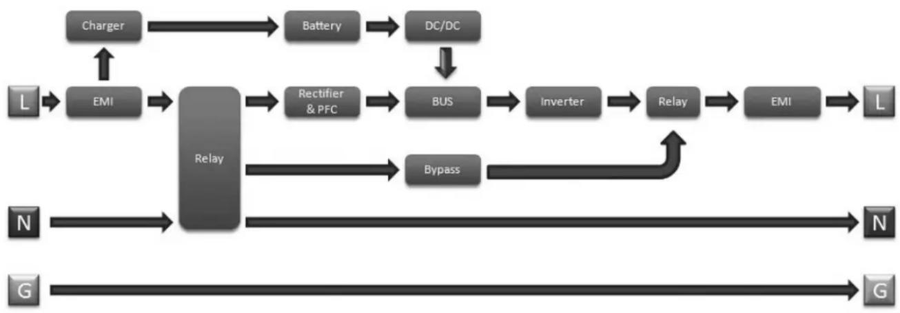
UPS Circuit Block Diagram
flowchart
graph TD
    A["Charger"] --> B["Battery"]
    B --> C["DC/DC"]
    C --> D["Rectifier & PFC"]
    D --> E["BUS"]
    E --> F["Inverter"]
    F --> G["Relay"]
    G --> H["EMI"]
    H --> I["L"]
    J["N"] --> K["Relay"]
    L["G"] --> M["Relay"]
    K --> N["Bypass"]
    M --> O["Relay"]
    N --> P["N"]
    O --> Q["G"]
    R["L"] --> S["EMI"]
    T["N"] --> U["Relay"]
    V["G"] --> W["Relay"]
    X["Charger"] --> Y["EMI"]
    Z["Reverbination"] --> AA["Bypass"]
Installation
Rack Mounting
Mount your equipment in either a 4-post or 2-post rack or rack enclosure. The user must determine the fitness of hardware and procedures before mounting. If hardware and procedures are not suitable for your application, contact the manufacturer of your rack or rack enclosure. The procedures described in this manual are for common rack and rack enclosure types and may not be appropriate for all applications.
4-Post Mounting
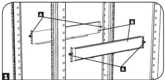
1 The included plastic pegs A will temporarily support the empty rackmount shelves B while you install the permanent mounting hardware. Insert a peg into the third hole from the top on the front end of each bracket. On the rear end, insert a peg into the center hole. (Each front bracket has 6 holes and each rear bracket has 5 holes.) The pegs will snap into place.
After installing the pegs, expand each shelf to match the depth of your rack rails. The pegs will fit through the square holes in the rack rails to support the shelves. Refer to the rack unit labels to confirm that the shelves are level in all directions.
Note: The support ledge of each shelf must face inward.
2 Remove the pegs at the front end of each bracket. Secure the shelves B to the mounting rails permanently using the included screws and cup washers C as shown. Place 2 screws at the front of each rail (4 total) and 2 screws at the back of each rail (4 total). Tighten all screws before proceeding.
Note: The rear pegs can be left in for installation, but the front ones must be removed before the bracket is secured by screws.
WARNING!
Do not attempt to install your UPS until you have inserted and tightened the required screws. The plastic pegs will not support the weight of your UPS.
3 Attach your UPS's mounting brackets D to the forward mounting holes E of the UPS using the included hardware F. The mounting bracket "ears" should face forward.
4 With the aid of an assistant (if necessary), lift your UPS and slide it into the shelves. Attach the UPS mounting brackets to the forward mounting rails with user-supplied screws and washers 6. Tighten all screws securely.
text_image
A B A 1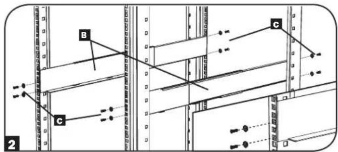
text_image
B C C 2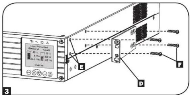
text_image
Linear Protected (battery)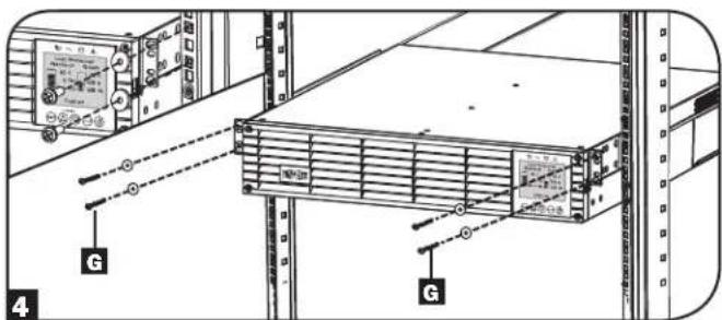
text_image
Technical diagram showing server rack with labeled components and connection points, including a monitor and indicator lights.2-Post Mounting
If you mount 2U UPS models in 2-post racks, they require the addition of a Tripp Lite 2-Post Rackmount Installation Kit (model: 2POSTRMKITWM, sold separately). See Installation Kit owner's manual for installation procedure.
Installation
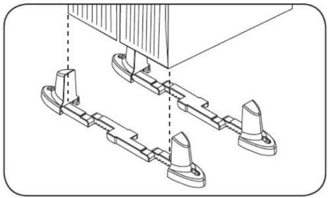
Tower Mounting
Your UPS can be mounted in an upright tower position with optional base stands sold separately by Tripp Lite (model: 2-9USTAND). When mounting the UPS on adjustable base stands, make sure that the control panel is toward the top. The control panel may be rotated to make it easier to read. Remove the 4 front screws from the front panel and take it off. Pinch the tabs located on the sides of the LCD panel, and then rotate it. Replace the front panel and secure it. Front panel setup should be operated by service personnel only.
WARNING!
All UPS systems are extremely heavy. Use caution when lifting and mounting. User must properly stabilize the UPS when lifting and mounting.
natural_image
Technical line drawing of mechanical components with no visible text or symbols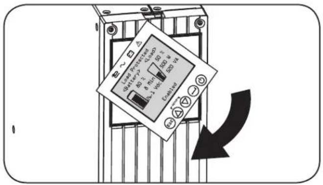
text_image
Load Protected 40 Ω 2Ω 8Ω 1Ω 50 Ω 2Ω LED V4 Coatings -30 +30 -30 +30 -30| UPS Model SUINT1000LCD2U SUINT1500LCD2U SUINT2200LCD2U SUINT3000LCD2U / SU3000LCD2UHV | |
| UPS Dimensions (H x W x D) | 8.6 x 43.8 x 39.6 cm 8.6 x 43.8 x 49.6 cm 8.6 x 43.8 x 49.6 cm 8.6 x 43.8 x 61.6 cm |
Operating Altitude: 0 to 3000 m
Installation
Smart Battery Communications Connection
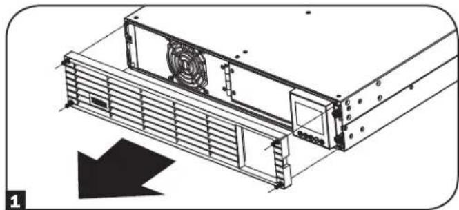
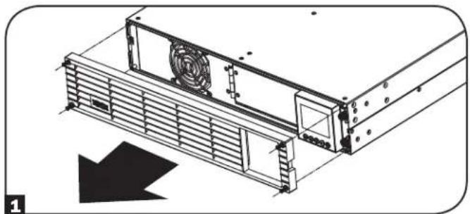
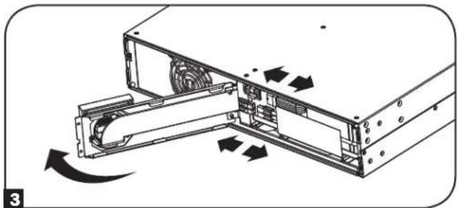
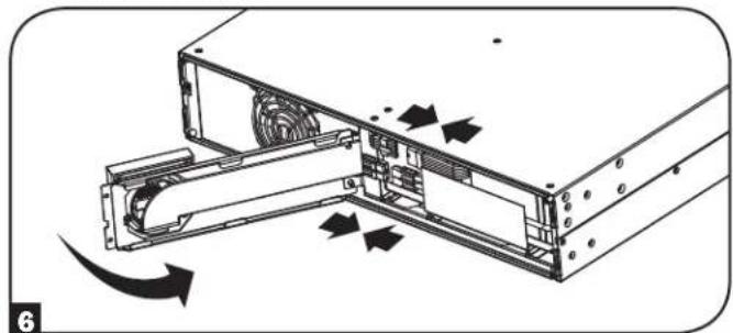
Your UPS supports automatic detection of its internal batteries and up to 6 external SMART BATTERY PACKS. Prior to powering up the UPS from AC mains power, you must connect the internal SMART BATTERY communication cable in the following manner:
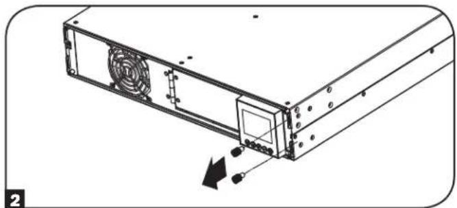
1 Remove the 4 front screws from the front bezel and take it off.
natural_image
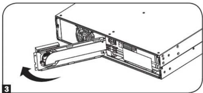
Technical line drawing of a server rack with ventilation duct and fan (no text or symbols)3 Open the front plate.
natural_image
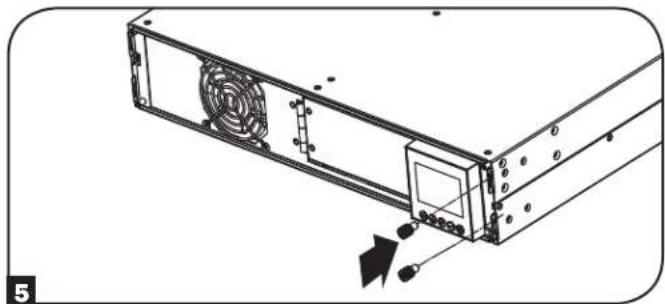
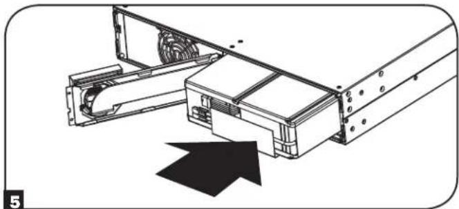
Technical line drawing of a computer drive assembly with a rotating component (no text or symbols)5 Tighten the 2 screws to secure the front plate.
natural_image
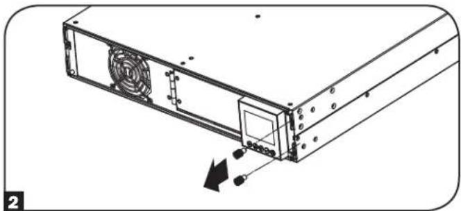
Technical line drawing of a computer tower with ventilation slots and drive components (no text or symbols)2 Loosen the 2 screws securing the front plate.
natural_image
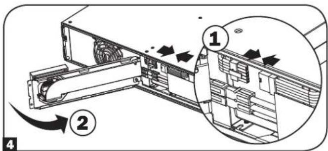
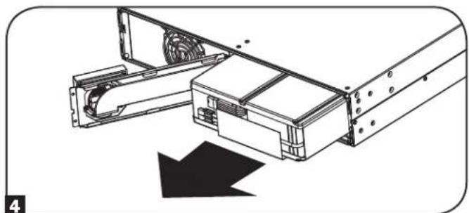
Diagram of a computer drive chassis showing fan, drive, and cable components (no text or labels)4 Connect the SMART BATTERY communication cable. Close the front plate.
text_image
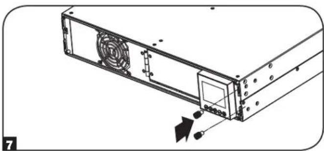
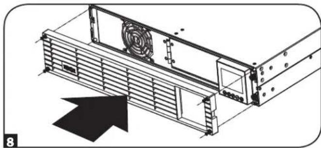
Technical diagram showing a device's internal structure with numbered annotations and directional arrows indicating flow or movement.6 Replace the 4 front screws to secure the bezel.
natural_image
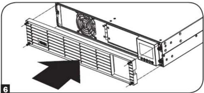
Technical line drawing of a server rack with fan and ventilation slots (no text or symbols)EXTERNAL BATTERY CONFIGURATION NOTE
If external battery packs are to be used with this UPS, install them following the mounting/installation documentation included with each battery pack. External battery pack installation requires the UPS be configured one of two ways:
- Via the UPS front panel LCD interface
- Via Tripp Lite's EXTERNAL BATTERY CONFIGURATION software
This UPS is factory programmed with discharge curves and charging profiles for external battery pack configurations accessible using the UPS front panel LCD interface. Additional battery pack options using larger or multiple external battery packs are also supported, but require configuration using Tripp Lite's EXTERNAL BATTERY CONFIGURATION software and a serial port connection to the UPS.
Basic Connection and Start-Up
Quick Start Guide - First Time UPS Power-On
Plug your UPS line cord into an electrical outlet
Your UPS must be connected to a dedicated circuit of sufficient amperage.
Refer to the rating table labelled on the UPS for more details.
2 Select your Language
When your UPS is plugged in for the first time, the INPUT AC LED will light up and the front panel LCD screen will request a language selection.
Using the UP / DOWN buttons Ⓐ, select your language preference, then press the NEXT ⏻ button.
The interface will confirm your selection and provide options to go back (press BACK ☑) or to go to the next step (press NEXT ☑).
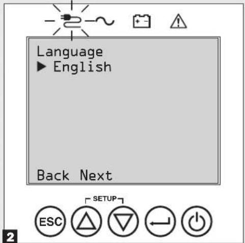
text_image
Language ► English Back Next ESC SETUP4 Select your Password
Next, the UPS will prompt you to pick the desired PASSWORD.
Using the UP / DOWN Ⓐ buttons, select the first digit of your desired password and press the NEXT ⏻ button to advance to the second digit. Repeat for digits 2 through 4.
Note: To quickly set the password to "0 0 0 0" press the NEXT button 4 times.
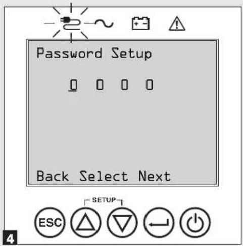
text_image
Password Setup Back Select Next ESC SETUP
natural_image
Line drawing of a hand inserting a plug into an electrical outlet (no text or symbols)3 Select your Power Strategy
Next, the UPS will prompt you to pick the desired POWER STRATEGY.
Using the UP / DOWN Ⓐ buttons, select your POWER STRATEGY preference and press the APPLY button.
See the Power Strategy Selection Options and UPS Operating Modes sections under the Operations section for operating characteristics of each power strategy.
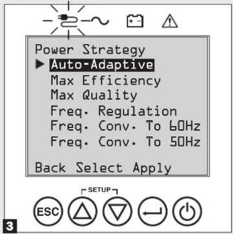
text_image
Power Strategy ► Auto-Adaptive Max Efficiency Max Quality Freq. Regulation Freq. Conv. To 60Hz Freq. Conv. To 50Hz Back Select Apply5 Select UPS Output Voltage
Next, the UPS will prompt you to select the desired OUTPUT VOLTAGE.
Using the UP / DOWN Ⓐ button, select the UPS output voltage, then select APPLY⊖.
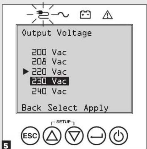
text_image
Output Voltage 200 Vac 208 Vac ▶ 220 Vac 230 Vac 240 Vac Back Select Apply ESC SETUPBasic Connection and Start-Up
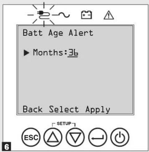
6 Select UPS Battery Age Alert
Next, the UPS will prompt you to select the timing of the BATTERY AGE ALERT.
Using the UP / DOWN Ⓐ buttons, select the timing of the battery age alert in months, then press APPLY⊖.
text_image
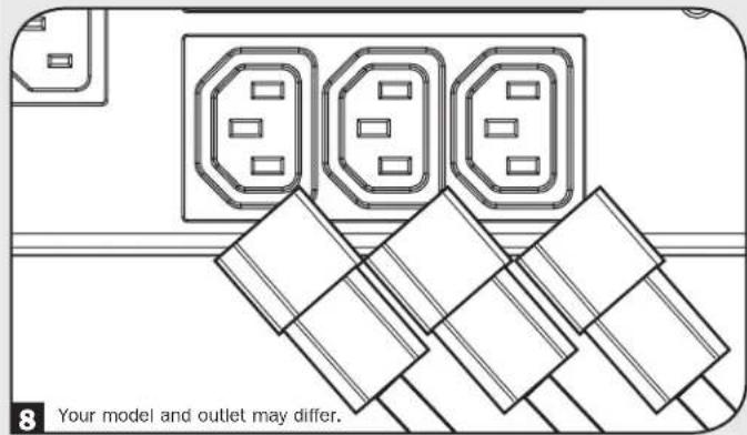
Batt Age Alert ► Months:36 Back Select Apply ESC SETUP8 Plug your equipment into the UPS
Your UPS is designed to support network, server and computer equipment only.
text_image
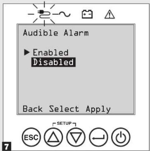
8 Your model and outlet may differ.7 Select Audible Alarm ENABLE / DISABLE status
Next, the UPS will prompt you to select the alarm ENABLE / DISABLE status.
Using the UP / DOWN Ⓐbuttons, select the alarm ENABLE / DISABLE status, then press APPLY⊖.
Note: Disabling the alarm prevents the audible alarm from sounding during power failures and UPS fault conditions only. The alarm will still "chirp" to confirm operator input via the front panel LCD navigation buttons when the alarm is set to disable.
text_image
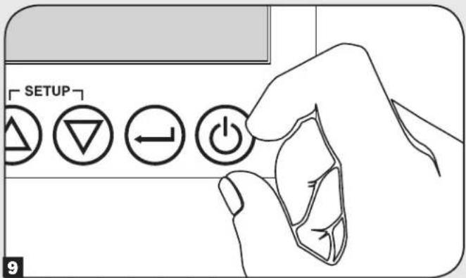
Audible Alarm ▶ Enabled Disabled Back Select Apply ESC SETUP9 Turn your UPS on
Press and hold the POWER ⏻ button for 3 seconds and release as the alarm begins to sound.
text_image
SETUP 9The UPS will then go through a series of diagnostic checks before turning on output power. Once the UPS reports the operating status of NORMAL / LOAD PROTECTED with the configured POWER STRATEGY enabled, your UPS can immediately be put into service to provide reliable protection from a wide variety of power problems.
Features
Before installing and operating your UPS, familiarize yourself with the locations and function of the features of each component.
Front Panel Controls, LEDs and LCD Screen
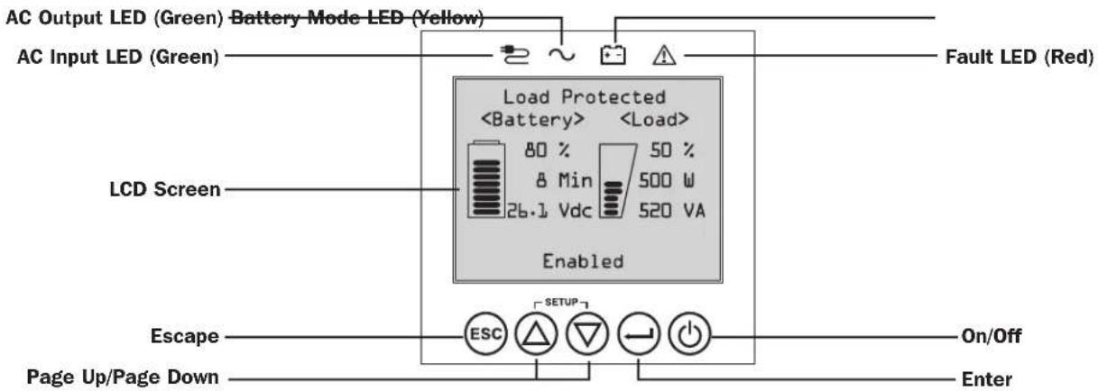
The graphical LCD on the front panel contains a wide range of UPS operating conditions and diagnostic data. It also displays UPS settings and options when viewing the UPS setup screens. The five buttons below the LCD can be used to navigate the various information, configuration and UPS control screens by following the on-screen prompts and selection options. Additional LED indicators above the LCD screen also provide at-a-glance status of AC input source, availability of output, battery status, and warning/fault status.
See Operations section for detailed descriptions of LCD functions, buttons and LEDs.
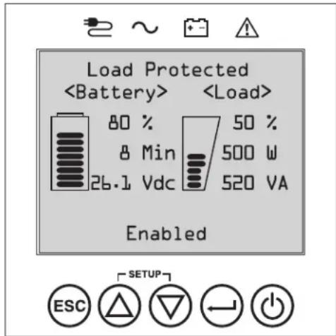
text_image
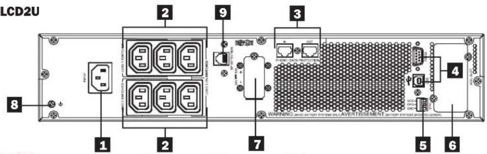
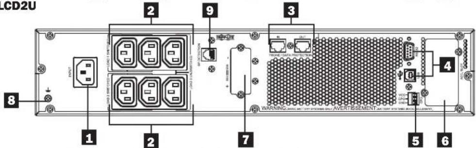
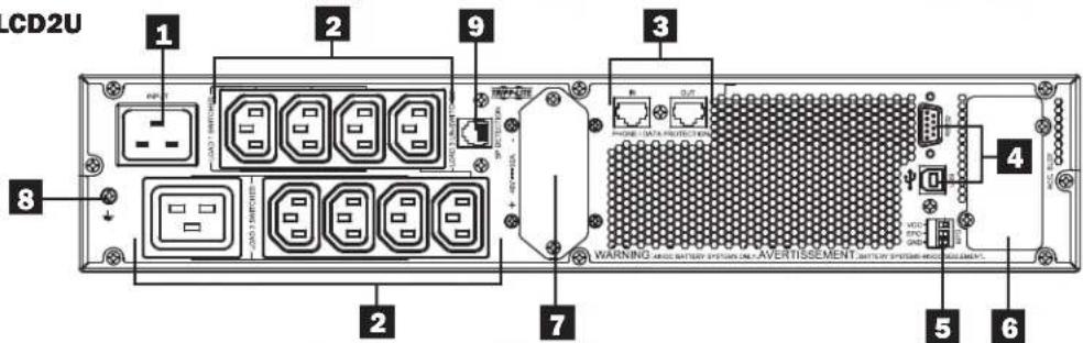
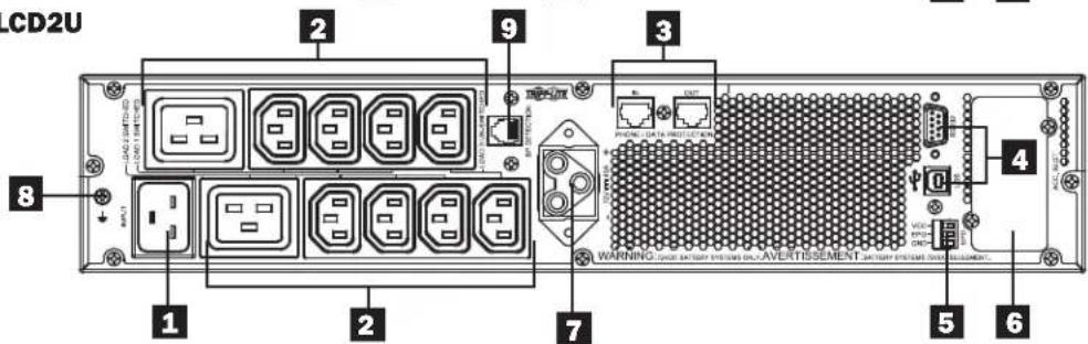
Load ProtectedRear Panel Features
1 Input Cord Connection: This connects to AC power via a user-supplied cord with country-specific plug or permanently attached power cord.
2 AC Receptacles (varies by model): These output receptacles provide connected equipment with pure sine-wave AC output during normal operation and battery power during blackouts and severe brownouts. Power provided by these outlets is filtered to protect connected equipment against damaging surges and line noise. The receptacles are divided into numbered load banks, as labeled on the unit. Using PowerAlert software and cabling, load banks one and two may be individually turned off and on from a remote location, allowing users to reset or reboot connected equipment.
3 Telephone or Telephone/Network Protection Jacks: These jacks protect your equipment against surges over a telephone line or telephone/network data line. Connecting your equipment to these jacks is optional. Your UPS will work properly without this connection.
Note: Not compatible with PoE (Power Over Ethernet) applications.
4 Communications Ports (USB or RS-232): These ports connect your UPS to any workstation or server. Use with Tripp Lite's PowerAlert Software and included cables to enable your computer to automatically save open files and shut down equipment during a blackout. Also use PowerAlert Software to monitor a wide variety of AC line power and UPS operating conditions. Consult your PowerAlert Software manual or contact Tripp Lite Customer Support for more information. The 9-pin RS-232 port also supports dry-contact communications. See USB & RS-232 Serial Communications in the Optional Connections section for installation instructions.
5 EPO (Emergency Power Off) Port: Your UPS features an EPO port that may be used to connect the UPS to a contact closure switch to enable emergency inverter shutdown. See Optional Connections section for details.
6 Accessory Slot: Remove the small cover panel from this slot to use optional accessories to remotely monitor and control your UPS. Visit tripplite.com to see a full list of accessories, including the WEBCARDLX for remote control and UPS monitoring, as well as a wide variety of network management and connectivity products.
7 External Battery Pack Connector (configuration varies by model): Your UPS supports the use of optional Tripp Lite external battery packs for additional runtime. See Model Specific Accessories section under the Overview section for compatible models and limitations and Configuring External Battery Packs section under Operations section for configuration instructions. Note: External battery pack options require configuration using front panel LCD Interface or via Tripp Lite's EXTERNAL BATTERY CONFIGURATION software.
8 Ground Screw: Use this to connect any equipment that requires a chassis ground.
9 External Battery Detection Port: For external batteries with communication built-in, plugging the battery communication cable into this port will allow the UPS to automatically detect the external battery.
Features
SUINT1000LCD2U
text_image
LCD2U 1 2 3 4 5 6 7 8 9 WARNING: AOC BATTERY EXCELLE ACVERTISSEMENT CATTERY SYSTEM AND EDITIONSUINT1500LCD2U
text_image
LCD2U 1 2 3 4 5 6 7 8 9 WARNING: 10.0V AC/AVERTISSEMENTSUINT2200LCD2U
text_image
LCD2U 1 2 9 3 8 2 7 WARNING AND BATTERY SYSTEM ON A VERTISSEMENT, BATTERY SYSTEM ON A VERTISSEMENT 4 5 6SUINT3000LCD2U
text_image
CD2U 1 2 3 4 5 6 7 8 9 WARNING: CIRI ORDER PRIOR DISERTISSEMENT CATCH SYSTEM AND ELEMENTSU3000LCD2UHV

text_image
3000LCD2UHV OUTPUT INPUT 1 2 8 1 2 9 3 7 WARNING: VCC BATTOR SPINION ON AVERTISSEMENT ANTERIOR PINTOLATION 4 5 6Operations
This section explains how to use your Tripp Lite Online UPS System, including front-panel LCD operation, operating modes, UPS startup and shutdown, transferring between modes, setting power strategy, and configuring bypass settings, load segments and battery settings.
LCD Front-Panel Display and Controls
There is a 5 button graphical LCD screen with additional LED indicators on the front of the UPS that provides information on UPS status, load level information, event information, measurements, settings and a wide variety of UPS configuration and power strategy options.
text_image
AC Output LED (Green) Battery Mode LED (Yellow) AC Input LED (Green) Load ProtectedLED Front Panel Indicators
There are 4 LEDs above the front panel LCD screen that offer information on AC INPUT, BYPASS, AC OUTPUT, BATTERY MODE and UPS FAULT status.

AC INPUT indicator
| OnWhen this LED is ON SOLID, AC input is of adequate quality for UPS operation in BYPASS or ECONOMY MODE. | AC input is available AND AC input is WITHIN the configured ECONOMY / BYPASS mode range. |
| Flashing | AC input is available AND AC input is OUTSIDE the configured BYPASS mode range.When this LED is ON FLASHING, AC input is not of adequate voltage or frequency for UPS operation in BYPASS or ECONOMY MODE. |
| Off AC input is NOT available.When this LED is OFF, AC input is not available. | |

AC OUTPUT indicator
On UPS AC output is ON
UPS output is available at the UPS output receptacles.
Off UPS AC output is OFF
UPS AC output is not available.

BATTERY MODE indicator
On UPS is running in battery mode
UPS batteries are discharging as the UPS runs in battery mode. Also lights momentarily during self-test operation.
Flashing UPS is running in battery mode - Low battery warning
UPS batteries are discharging as the UPS runs in BATTERY mode and are becoming low. The indicator will flash at 2 second intervals to report LOW BATTERY and 0.5 second intervals to report BATTERIES ARE NEAR FULLY DISCHARGED and the UPS is near shutdown.

UPS FAULT indicator
| On UPS is experiencing a pre-defined fault state | |
| See front panel display for explanation of error state or code information. See on-screen instructions and manual for troubleshooting tips. | |
| Off | Normal |
| UPS is not reporting fault conditions when this indicator is OFF. | |
Operations
Front Panel Button Functions
There are 5 front panel buttons that offer UPS control and configuration options. To navigate the various information, configuration and UPS control screens, use the 5-button front panel interface and follow the on-screen prompts and selection options.

Power On / Off Button: This control offers three main functions: Power-On, Power-Off and Clear UPS Fault.
To turn the UPS ON into a protected operating mode, press and hold this button for 3 seconds as the UPS is connected to input AC power. Release the button when the alarm begins to sound and the UPS will startup into the last configured power strategy.
To "cold start" the UPS on into battery mode during power failure conditions, press and hold this button for 3 seconds. Release the button when the alarm begins to sound and the UPS will startup in battery mode.
To turn the UPS OFF as it's running in battery or protected mode, press and hold this button for 3 seconds. Release the button when the alarm begins to sound. The UPS will turn off AC output. Once AC output is off, disconnect input power to the UPS and the UPS will power off completely.
To CLEAR UPS FAULT, press and hold this button as directed on-screen for 3 seconds. The UPS will clear the fault conditions and return to standby or bypass mode.

ENTER Button: This control is used to make selections, confirm options and move forward to the next selection as the UPS is configured in setup mode. Press this button as directed on-screen in Setup mode to Enter, Confirm or Move Forward in the configuration process.

UP / DOWN Buttons: These controls offer two main functions: "Up" and "Down" directional control, plus enter / exit setup mode (when pressed simultaneously). These buttons are used to navigate setup-mode menu options and scroll up or down to view screen contents as necessary.

To ENTER or EXIT UPS SETUP MODE, press these two buttons simultaneously for 3 seconds. Release the button when the alarm begins to sound. The UPS will automatically enter setup mode if both buttons are pressed during LCD display modes. The UPS will automatically exit setup mode if both buttons are pressed as the UPS runs in UPS setup mode.

ESCAPE Button: This control offers three main functions: Alarm Cancel, Clear Fault and Back / Cancel operations.
To CANCEL UPS ALARM, press this button. If a new alarm condition occurs, the alarm will sound again.
To CANCEL or GO BACK ONE LEVEL, press this button as directed on-screen in Navigation and Setup modes.
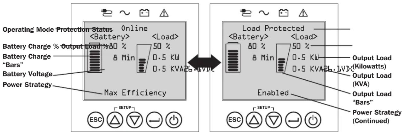
Home Screen Layout
The UPS front panel LCD screen is set up to provide continuous UPS operating information using NORMAL MODE and BATTERY MODE home-screens that continuously report operating mode, protection status, power strategy and a number of battery and load-level operating parameters.
Normal Mode Home Screens
text_image
Operating Mode Protection Status OnlineOperations
Power Strategy Selection Options
Tripp Lite SmartOnline LCD UPS systems offer several built-in power strategy options that enable the UPS to optimize performance to meet user needs for MAXIMUM POWER QUALITY, MAXIMUM EFFICIENCY, and FREQUENCY REGULATION or FREQUENCY CONVERSION operation. An additional AUTO-ADAPTIVE power strategy combines the benefits of high-efficiency and maximum power quality. Each power strategy option enables the UPS to automatically shift between specific operating modes as power and UPS status dictates. Available power strategy options include:
- Auto-Adaptive Power Strategy enables the UPS to automatically switch between ONLINE MODE and ECONOMY MODE as dictated by the quality and reliability of UPS input power. If the UPS does not experience a power failure in a week's time (not including UPS self-test) the UPS will automatically switch to ECONOMY MODE. If a power failure occurs, the UPS will maintain output in BATTERY MODE. When power is restored, the UPS will repeat the cycle by running in ONLINE MODE until there are no power failures for one week's time.
- Max-Efficiency Power Strategy enables the UPS to run continuously in ECONOMY MODE anytime incoming AC power is within the configured bypass low/high voltage range. If UPS input voltage is outside the configured bypass range, the UPS will automatically switch to ONLINE MODE until AC input voltage is restored within the configured bypass voltage range. This is similar to Auto-Adaptive Power Strategy, except transfer to ECONOMY MODE is immediate as voltage levels recover. There is no one-week time period of power failure free operation required in order for the UPS to return to ECONOMY MODE operation.
- Max-Quality Power Strategy enables the UPS to run continuously in ONLINE MODE the entire time incoming AC power is within the range for online mode operation. The UPS will remain operating continuously in Online Double-Conversion mode, providing the highest quality output power with zero transfer time. Auto-bypass mode is available during UPS failure modes when AC input is within the bypass range.
- Frequency Regulation Power Strategy is similar to Max-Quality Power Strategy, except the UPS will actively regulate output frequency within +/-0.05Hz of the 50 or 60Hz nominal frequency measured on startup. The UPS will remain operating continuously in Online Double-Conversion mode, providing the highest quality output power with zero transfer time. Auto-bypass mode is available during UPS failure modes when AC input is within the bypass range.
- Frequency Conversion to 60Hz & Frequency Conversion to 50Hz Power Strategies are similar to Max-Quality power strategy, except the UPS will actively regulate output within +/-0.05Hz of the 50Hz (Freq. Conv. to 50Hz setting) or 60Hz (Freq. Conv. to 60Hz setting). Auto-bypass is not available in FREQUENCY CONVERSION mode. Typical applications include converting 50 to 60Hz (or 60 to 50Hz) for sensitive electronic devices.
Note: Maximum power supported in Frequency Regulation/Conversion modes is derated by 30%.
UPS Operating Modes
Tripp Lite SmartOnline UPS systems are able to automatically switch between operating modes under conditions specified in the configured Power Strategy. The UPS continuously indicates status using front panel LEDs and the interactive LCD viewing screen.
- Battery Mode is the UPS system's automatic response to power failures and voltage variations outside of the online voltage range. In BATTERY MODE, the UPS maintains sine wave AC output power from battery reserves. Once power is restored, the UPS will return to the protected operating mode as dictated by the configured power-strategy and input power conditions.
- Online Mode (also known as ONLINE, DOUBLE CONVERSION MODE) offers the highest level of UPS equipment protection. In ONLINE MODE, the UPS actively regenerates power from AC to DC, then from DC to AC to provide continuously regulated AC output within 2% of the selected nominal output voltage with zero transfer time as the UPS switches between ONLINE and BATTERY modes.
- Economy Mode offers power saving operation with the highest level of UPS operating efficiency. In ECONOMY MODE, the UPS saves energy by turning off the online, double-conversion process whenever input power is within the ECONOMY MODE voltage range. If line voltage falls outside of the ECONOMY MODE, the UPS will respond by automatically switching to ONLINE MODE until line voltage recovers.
- Frequency Regulation Mode gives the UPS the ability to correct frequency variations present on UPS input power. See Power Strategy Selection Options section for details.
- Frequency Conversion to 60Hz and Frequency Conversion to 50Hz Modes give the UPS the ability to convert frequency from 50Hz to 60Hz (or 60Hz to 50Hz). See Power Strategy Selection Options section for details.
Note: Maximum power supported in Frequency Regulation/Conversion modes is derated by 30%. - Bypass Mode offers filtered and unregulated power to connected equipment.
Operations
Power Strategy Operating Features and Supported UPS Operating Modes
The configured UPS Power Strategy provides a framework for UPS operation as it switches between operating modes as dictated by power events and UPS status. Each Power Strategy offers a unique set of operating parameters that the UPS adheres to in order to meet user preferences for high-performance or high efficiency. Additional frequency regulation and conversion options are also available for advanced applications. The chart below lists the UPS operating modes supported for each Power Strategy option.
| UPS OPERATING MODESUPS automatically switches operating modes as dictated by the configured power strategy, current power and UPS status conditions. | |||||
| Support for ONLINE MODE | Support for ECONOMY MODE | Support for BATTERY MODE | Support for AUTO-BYPASS | ||
| POWER STRATEGY SELECTION OPTIONSSYour power strategy selection enables the UPS to switch between operating modesas described | AUTO ADAPTIVEUPS runs continuously in ECONOMY MODE after running in ONLINE MODE for one continuous week without a power failure. | YES. When input is within the ONLINE voltage range, but outside the BYPASS voltage range, and after AC power is restored. | YES. When input is within the ECONOMY MODE voltage range and there are no power failures for one week. | YES. YES. In the event of | UPS inverter fault while input voltage is within the BYPASS voltage range. |
| MAX. QUALITYUPS runs in ONLINE MODE continuously to maintain the highest quality output power for connected equipment. | YES. When input is within the ONLINE voltage range. | NO. YES. YES. In the event of | UPS inverter fault while input voltage is within the BYPASS voltage range. | ||
| MAX. EFFICIENCYUPS runs in ECONOMY MODE full time when input is within the bypass range. | YES. When input is within the ONLINE voltage range, but outside the BYPASS voltage range. | YES. When input is within the ECONOMY MODE voltage range. | YES. YES. In the event of | UPS inverter fault while input voltage is within the BYPASS voltage range. | |
| FREQUENCY REGULATIONUPS regulates output to within +/-0.05Hz of nominal. | YES. When input is within the ONLINE voltage range.* | NO. YES. YES. In the event of | UPS inverter fault while input voltage is within the BYPASS voltage range. | ||
| FREQUENCY CONVERSION to 60HzUPS converts 50Hz input to 60Hz. (+/-0.05Hz) | YES. When input is within the ONLINE voltage range.** | NO. YES. NO. | |||
| FREQUENCY CONVERSION to 50HzUPS converts 60Hz input to 50Hz. (+/-0.05Hz) | YES. When input is within the ONLINE voltage range.** | NO. YES. NO. | |||
* LCD displays FREQUENCY REGULATION as the operating mode with derating information.
** LCD displays FREQUENCY CONVERSION as the operating mode with derating information.
Operations
Front Panel LCD Selection and Configuration Options
| MAIN MENU / SUBMENU DISPLAY / SETTING OPTIONS DISPLAY / SETTING DESCRIPTION | ||
| STATUS | ||
| Load Status • Load level (%, kW, kVA, A, | PF)• Available capacity (%, kW, kVA) | UPS load percent (%), kilowatt (kW), kilovoltamp (kVA), amp (A) & power factor (PF).UPS capacity available in percent (%), kilowatts (kW) & kilovoltamps (kVA). |
| In/Out Status • Input voltage & frequency | (Vac, Hz)• Output voltage & frequency (Vac, Hz)• Load Group1 (On, Off)• Load Group2 (On, Off) | Displays UPS input and output status information for input / output voltage (Vac), frequency (Hz) and outlet group power status (On/Off) information. |
| Energy Status • Efficiency (%) | • Avg. Power (kw/hr.)• Configured power strategy | Displays UPS efficiency percentage (%, connected equipment kilowatt hour consumption (kw/hr.) and configured power strategy. |
| Int. Batt. Status • Installed (mm/dd/yyyy) | • Expires (mm/dd/yyyy) | Displays internal Replacement Battery Cartridge install date and user configured expiration date. |
| Ext. BP. Status • Battery pack model & serial number | • Installed (mm/dd/yyyy)• Expires (mm/dd/yyyy) | Displays external Battery Pack model number & serial number (Tripp Lite SMART BATTERY PACKS) only, installation date and user configured expiration date. |
| Power Flow Chart | • View UPS operational flow chart | Displays UPS operating mode in a graphical flow chart. |
| CONTROL | ||
| Start Batt. Test | • Initiates a manual battery test | Initiates a momentary UPS battery self-test with immediate Pass/Fail results. |
| Reset Batt. Age | • Resets the battery age | Resets battery age to today's date. Use this option after NON-SMART battery replacement. |
| Reset Fault State | • Resets any fault state messages | Use this option to clear UPS fault messages. |
| Auto Batt. Testing | • Set regular battery self-test interval○ Disable○ 4 weeks (factory setting)○ 13 weeks○ 26 weeks | Use this option to initiate automatic UPS battery testing at regular intervals. |
| EVENT LOG | ||
| On Batt. Events | • Event counter(UPS On-battery events only)• Total minutes (total minutes of on-battery mode operation)• Most recent power failure (date)• Days until battery replacement alert (days)• Event details (date, time & description for the last 20 logged events) | Displays a summary of all ON-BATTERY events where the UPS switched to battery mode in response to a protected condition. Event details lists the last 20 battery events. As additional alerts occur, the oldest records will be automatically removed. |
| All Events | • Event counter (all events)• Most recent event (date)• Date time log• Event details (date, time and description of each logged event) | Displays a summary of all Recorded events. Event details lists the last 20 events. As additional alerts occur, the oldest records will be automatically removed. |
| Reset Batt. Events | • Resets battery events only | Resets all data in the on-battery events screen set. |
| Reset All Events • Resets all events | Resets all data in the all events screen set. | |
| SETTINGS | ||
| Basic setup | System• Current date (display, set date)• Current time (display, set time)• Audible alarm (enable, disable)• Language (select) | Displays, sets and resets date, time, audible alarm status and language settings.Note: Audible Alarm DISABLE setting prevents power fail and operating fault alarms only, the UPS will always “beep” to confirm the UPS is accepting user input from the front-panel LCD navigation buttons. |
| Output voltage• 200• 208• 220• 230• 240 | Use the SETTINGS / BASIC / OUTPUT VOLTAGE option to display or set the nominal UPS output voltage (changes take effect on next restart). | |
Operations
| MAIN MENU / SUBMENU DISPLAY / SETTING OPTIONS DISPLAY / SETTING DESCRIPTION | ||
| SETTINGS | ||
| Basic setup(continued) | Power strategy:• Auto-Adaptive• Max Efficiency• Max Quality• Freq. Regulation• Freq. Conversion to 60Hz• Freq. Conversion to 50Hz | Use the SETTINGS / BASIC / POWER STRATEGY option to display or set the UPS Power strategy.See Power Strategy Selection Options section under the Operations section for more info on the available power strategy options. |
| Battery:• External battery configuration○ Configure via UPS○ PC configured○ Battery Replacement• Battery Age Alert | Use the SETTINGS / BASIC / BATTERY option to configure the UPS with external battery packs. Battery replacement option can be used to update installation date for non-smart external battery replacement of the same type. Also sets the battery age alert duration for battery replacement reminder.See Configuring External Battery Packs section under the Operations section for information on how to configure external battery packs. | |
| Advanced setup | System:• Display brightness○ High○ Medium (factory setting)○ Low• Backlight dim: Enter 10-120 seconds (factory setting is 60 seconds)• Password: Set your 4 digit password (factory setting is 0000)• Factory reset (resets all UPS preferences to factory settings, including battery configurations) | Use the SETTINGS / ADVANCED / SYSTEM option to set the display brightness, the display backlight dim time-out, password or factory reset options. |
| In/Out:• Overload Alert Lvl: Enter a value 5-105% (factory setting is 100%) | Use SETTINGS / ADVANCED / IN-OUT for these options:Sets the UPS output load percentage before an overload alert is sent. | |
| Conf. Fault Action (UPS response to fault)○ Go to bypass (factory setting)○ Go to standby | Sets the UPS response to fault conditions that require the UPS to exit double-conversion mode. GO TO BYPASS option maintains AC output (so long as input voltage is within bypass high/low limits). GO TO STANDBY option causes the UPS to turn off output AC in response to fault conditions. | |
| • Bypass Low Limit: Enter a value -5% to -20% (factory setting is -15%) | Specifies the lowest acceptable input voltage for bypass operation. | |
| • Bypass High Limit: Enter a value +5% to +20% (factory setting is +10%) | Specifies the highest acceptable input voltage for bypass operation. | |
| On/Off:• Cold Start○ Enable (factory setting)○ Disable | Use SETTINGS / ADVANCED / ON-OFF for these options:Enabling Cold-start allows the UPS to be manually turned on into battery mode during a power failure. | |
| • Auto Restart○ Enable (factory setting)○ Disable | Enabling Auto-restart allows the UPS to automatically turn back on into a protected operating mode when power is restored. | |
| • Auto Restart Delay○ Enter: 0 to 60 seconds (factory setting is 5 seconds) | Auto-restart delay forces the UPS to wait 0-60 seconds after power is restored before automatically restarting.Requires that Auto-restart when power is restored be enabled. | |
| • Energy Saving○ Enter: 0-100%○ Disable (factory setting) | Energy saving enables the UPS to automatically shutdown when the output load is less than the selected percentage continuously for 5 minutes. | |
| • Off Mode○ Standby○ Bypass (factory setting) | Off mode setting of BYPASS allows the UPS to provide unregulated line power within configured bypass low / high limits to be available at the output of the UPS when it is turned off. | |
| • Min. Batt to Restart○ Enter: 10-90%○ Disable (factory setting) | Minimum battery charge level to restart forces the UPS to wait until batteries have recharged to the selected percentage before automatically restarting.Note:UPS can be manually started using the power button if battery is below the minimum battery restart threshold.Requires that Auto-restart when power is restored be enabled. | |
Operations
MAIN MENU / SUBMENU DISPLAY / SETTING OPTIONS DISPLAY / SETTING DESCRIPTION
| SETTINGS | ||
| Advanced setup(continued) | On battery:Low Batt. AlertEnter: 10-90% (factory setting is 20%) | Enables the UPS to send a low-battery alert as batteries discharge to the selected charge level during a power failure. |
| Timed ShutdownEnter: 15, 30, 45 sec., 1-30 min.Disable (factory setting) | Timed shutdown sets the maximum amount of battery runtime in seconds or minutes the UPS will provide during a power failure. Use the DISABLE setting for the longest possible battery runtime. | |
| Low Battery ShutdownEnter: 5-100%Disable (factory setting) | Low battery shutdown sets the maximum amount of battery discharge before the UPS shuts down due to low battery. The setting of DISABLE allows the batteries to discharge to 0% before shutdown. | |
| On Batt. Beep DelayEnter: 0-120 seconds(factory setting is 5 seconds) | The “Beep Delay” setting allows the audible alarm to be delayed up to 120 seconds to prevent the audible-alarm from sounding in response to short duration power failures. | |
| Shutdown CompletionRequired (factory setting)Interrupt OK | The UPS will communicate shutdown messaging to connected systems prior to UPS shutdown. The setting of INTERRUPT OK will interrupt shutdown messaging if power is restored after shutdown messaging is sent. | |
| USB/DB9 Settings:DB9 SettingsOutput pins 1&5- On battery (factory setting)- On bypass- Output on- Low battery | The UPS will signal the selected condition by shorting pins 1&5 on the DB9 port. | |
| Output pins 8&5- On battery- On bypass- Output on- Low battery (factory setting) | The UPS will signal the selected condition by shorting pins 8&5 on the DB9 port. | |
| Input pins 3&9- Shutdown (factory setting)- Output off-Reboot- Output on- Power Toggle | The UPS will perform the selected action when pins 3&9 are shorted on the DB9 port for at least 3.8 seconds.For the Reboot option (output off for 30 seconds before reboot): Note the pins must be shorted for at least 3.8 seconds to perform the reboot. The reboot happens at exactly 3.8 seconds. If the pins continue to be shorted for more than 3.8 seconds, no further action should be taken. The UPS takes no action on release of the short.The Power Toggle option is intended to keep the unit powered on whenever the pins are not shorted and powered off whenever the pins are shorted. Note this input cannot power on the unit from an off state unless valid AC is applied (this function will not impose a coldstart). To power on, the pins must be not shorted for at least 3.8 seconds and AC must be valid. To power off, the pins must be shorted for at least 3.8 seconds. | |
| USB signal lostLine mode setup-No action (factory setting)- Reboot UPS after delay-Reboot Load1 after delay-Reboot Load2 after delay | The UPS will perform the selected action if the USB signal from a connected device is lost in line power mode for the duration selected. | |
| Battery mode setup- Run to low battery (factory setting)- Shutdown after delay | The UPS will perform the selected action if the USB signal from a connected device is lost in battery power mode for the duration selected. | |
| USB lost timer- Enter: 10-60 seconds- Factory setting: 30 seconds | This control sets the duration of USB signal loss before the selected line power-mode / battery power-mode action engages. | |
| ABOUT | ||
| UPS Information UPS model number, UPS Serial number,UPS installed date | UPS installed date is automatically set by the unit after 2 hours of continuous operation. | |
| Network ID Web management accessory card firmware,IPv4 address, IPv6 address, MAC Address | ||
| Firmware UPS firmwares | ||
Operations
Configuring External Battery Packs
Tripp Lite SmartOnline INT UPS systems support the connection of external battery packs to enable extended-run UPS operation. In order for the UPS to provide efficient charging levels and accurate runtime predictions for optimal network runtime prior to sending auto-shutdown messaging, external battery packs need to be configured to the UPS upon installation.
There are 3 methods available to configure external battery packs to the UPS, depending on battery pack selected and quantity added to the UPS. Some battery pack configurations may require the use of more than one configuration method.
| EXTERNAL BATTERIES can be configured to the UPS... | ...AUTOMATICALLY(Using SMART Battery Packs) | ...MANUALLY(Using LCD Screen) | ...Using EXTERNAL BATTERY CONFIGURATION SOFTWARE |
| Battery Pack Compatibility | UPS supports automatic detection of up to 6 SMART BATTERY PACKS connected to the UPS. | LCD screen can be used to configure NON-SMART BATTERY PACKS and any additional SMART BATTERY PACKS beyond the 6 that can be automatically detected. | External Battery Configuration software can be used to configure the UPS for any supported quantity of SMART & NON-SMART external battery packs. |
Tripp Lite SMART Battery Packs include a wired data connection that enables automatic detection and configuration for up to 6 SMART Battery Packs to the UPS. Tripp Lite Legacy NON-SMART battery packs are also supported for extended runtime applications, but require user configuration using the front-panel LCD screen or through the use of EXTERNAL BATTERY CONFIGURATION SOFTWARE.
SmartOnline LCD SMART and NON-SMART External Battery Pack Options
| SUINT1000LCD2U SUINT1500LCD2U SUINT2200LCD2U | SUINT3000LCD2U / SU3000LCD2UHV | |||
| Supported “SMART”BATTERY PACKS | BP24V36-2US BP36V27-2US | BP48V27-2US BP72V18-2US | ||
| Supported LEGACY“NON-SMART”BATTERY PACKS | BP24V15RT2U (limit 1)BP24V28-2U (limit 1)BP24V70-3U | BP36V15-2U (limit 1)BP36V42-3U | BP48V24-2U (limit 1)BP48V60RT3U | BP72V15 (limit 1)BP72V28RT3U |
Configuring SMART and NON-SMART BATTERY PACKS via the front panel LCD screen
Adding up to 6 SMART BATTERY PACKS to the UPS
Each SmartOnline UPS has a designated SMART BATTERY PACK, where up to 6 SMART battery packs can be connected to the UPS for fully automatic detection and configuration. SMART battery packs include a wired data connection that connects to the UPS Battery Pack Detection port for automatic recognition and configuration by the UPS.
To configure the UPS for use with up to 6 SMART BATTERY PACKS, just connect the included POWER and DATA cables between the UPS and the first SMART BATTERY PACK. Then connect the POWER and DATA cables for additional SMART BATTERY PACKS to the one ahead of it. The UPS will automatically detect and configure up to 6 SMART BATTERY PACKS to the UPS.
Adding more than 6 SMART BATTERY PACKS to the UPS
SmartOnline UPS systems support automatic detection of up to 6 SMART BATTERY PACKS as described above. It is possible to configure the UPS for more than 6 SMART BATTERY PACKS by configuring all additional SMART PACKS as NON-SMART. When configuring the UPS with more than 6 SMART BATTERY PACKS, configure BPs #1-6 using the BP Detection port method listed above. Then configure SMART BATTERY PACKS #7 and above and any other supported battery pack models to be connected as NON-SMART BATTERY PACKS. See the ADDING NON-SMART Battery Packs section for more information.
Adding BATTERY PACKS to the UPS manually (SMART and NON-SMART battery packs)
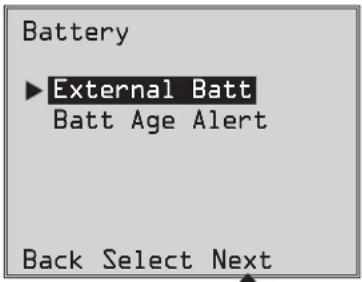
If you're connecting more than the 6 SMART Battery Packs the UPS can automatically detect OR are connecting supported NONSMART Battery Packs to the UPS, you can configure them via the UPS front panel LCD interface. First, install the Battery Pack power connections to the UPS as described in the battery pack documentation. Then, using the SETTINGS / BASIC SETTINGS / BATTERY configuration screens, select the EXTERNAL BATT menu option (see the Front Panel Button Functions and Front Panel LCD Selection and Configuration Options sections under the Operations section for instructions on accessing this section).
1 From the SETTINGS / BASIC SETTINGS / BATTERY menu, select EXTERNAL BATT, then press NEXT ☑.
text_image
Battery ► External Batt Batt Age Alert Back Select NextOperations
2 The LCD screen will display the present configuration settings. Press NEXT ⊖ to edit the configuration.
3 Then select CONFIGURE VIA UPS and press NEXT ⊖.
4 The LCD screen will prompt you to move to the next screen where the SMART and NON-SMART battery packs can be configured.
Then select NEXT ⊖...
Note: The display will cycle between two screens to show all the text.
Configure via UPS
Press NEXT to view detected SMART BPs (S column) and specify NONSMART BP qty (N column).
Back Next
External Batt
Note Presently configured via UPS on 04/07/2014 Press Next to change
Back Next
External Batt
Configure via UPS PC Configured External Batt
Back Select Next
Configure via UPS
SMART BPs beyond qty b must be configured as NONSMART.
Back Next
5 The LCD screen will display the list of supported external battery packs preceded by a column displaying the number of configured SMART and NON-SMART external battery packs. SMART BATTERY PACKS detected via the BP DETECTION PORT will already be listed with the appropriate quantity of 1-6 under the "S" Column of this screen.
To configure NON-SMART batteries and any SMART batteries beyond the 6 that were auto-detected, use the UP/DOWN Ⓐ and NEXT ⏱ buttons. After the last battery pack on the list is configured, press BACK ⏱ to edit your entry or APPLY ⏱ to enter the new values.
Note: The "S" column displays the number of configured SMART battery packs and the "N" column displays the number of configured NON-SMART battery packs.
Note: Pressing the UP or DOWN buttons change the "N" column value. Pressing the NEXT button moves the cursor down one row.
Note: When you reach the last row, NEXT will change to APPLY.
6 After the manually entered NON-SMART battery packs have been applied to the UPS, the LCD will report that the change has been accepted and will suggest you verify that the actual set of external battery packs match the UPS configuration.
Press NEXT ☑ to move to the next screen.
Configure via UPS
Change accepted. For true capacity and runtime reporting, verify connected BPs match configuration
Back Next
Configure via UPS
S+N Pack
0 0 BP48V24-2U 0 0 BP48V60RT-3U 0 0 BP48V24-2US
Back Select Next
Configure via UPS entered.
Back Next
7 The LCD screen will ask you to press NEXT ⊖ to enter the battery installation date for manually configured external battery packs.
The following screen allows you to pick the current date for installation, or allow you to enter an installation date in the past, in case the BP was added at a previous date.
Configure via UPS
Press Next to enter Battery Installed Date for manually added battery packs.
Back Next
Optional Connections
Your UPS will function properly without these connections.
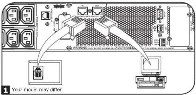
1 Phone Line or Phone/Network Line Surge Suppression
Your UPS has jacks which protect against surges on a phone line.* Using appropriate telephone or network cords, connect your wall jack to the UPS jack marked "IN." Connect your equipment to the UPS jack marked "OUT." Make sure the equipment you connect to the UPS's jacks is also protected against surges on the AC line.
* Not compatible with PoE (Power Over Ethernet) applications.
Note: Use the same type of connector for the phone line surge suppression input and output ports.
2 USB and RS-232 Serial Communications
Use the included USB cable (see 2a) and/or RS-232 serial cable (see 2b) to connect the communication port of your computer to the communication port of your UPS. Install on your computer the Tripp Lite PowerAlert Software appropriate to your computer's operating system. Your UPS may feature additional communications ports; these ports may be connected to additional computers that have PowerAlert Software installed. Consult your PowerAlert manual for more information.
2c RS-232 Dry contact communications are simple, but some knowledge of electronics is necessary to configure them. The RS-232 port's pin assignments are shown in the diagram. If the UPS battery is low, the UPS sends a signal by bridging pins 8 and 5. If utility power fails, the UPS sends a signal by bridging pins 1 and 5. To shut the UPS down remotely, short pin 3 to pin 9 for at least 3.8 seconds. Additional functions of these pins can be configured through the LCD or via Web management accessory card communication.
text_image
WARNING: www.163.com.cn WARNING: www.163.com.cn Your model may differ.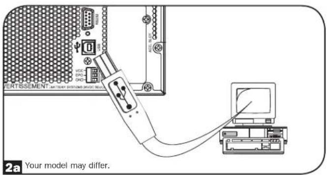
text_image
VERTISSEMENT VDC END GND 2a Your model may differ.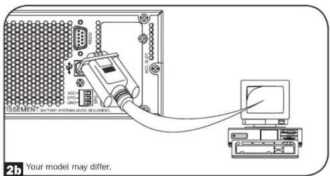
text_image
TSSEMENT BATTERY SYSTEMS INFOE SELEMENT. 2b Your model may differ.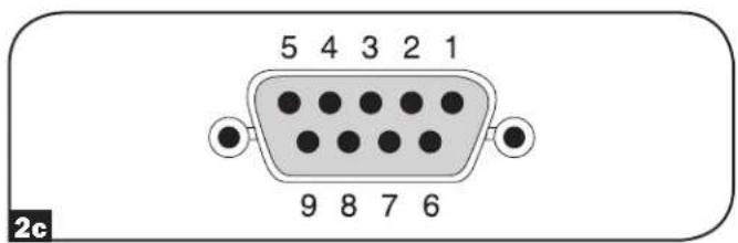
text_image
5 4 3 2 1 9 8 7 6 2cOptional Connections
3 EPO Port Connection
This optional feature is only for those applications that require connection to a facility's Emergency Power Off (EPO) circuit. When the UPS is connected to this circuit, it enables emergency shutdown of the UPS's inverter and inhibits transfer to internal bypass. Connect the EPO port of your UPS (see 3a) to a user-supplied normally closed or normally open switch according to the circuit diagram (see 3b).
Note: If a non-latching EPO switch is used, the EPO must be held for a minimum of 1 second. This does not apply to a latching EPO switch.
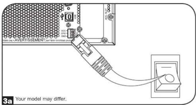
text_image
3a Your model may differ.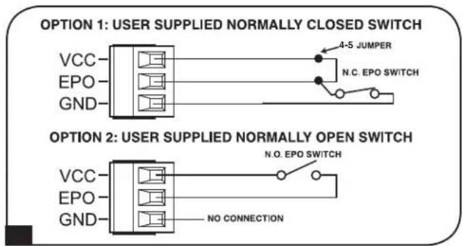
text_image
OPTION 1: USER SUPPLIED NORMALLY CLOSED SWITCH VCC EPO GND 4-5 JUMPER N.C. EPO SWITCH OPTION 2: USER SUPPLIED NORMALLY OPEN SWITCH VCC EPO GND N.O. EPO SWITCH NO CONNECTIONUPS state when asserting EPO with valid AC input present:
| AC Output LCD Screen Status LEDs Status | ||
| Off EPO Active Only AC Input Indicator is On. |
To restart the UPS after EPO assertion with valid AC input present:
- Verify that the EPO assertion has been removed or cleared.
- Press and hold the POWER ON/OFF button until it beeps. Now the UPS will start back up in one of the pre-configured normal operating modes.
UPS state when asserting EPO without valid AC input present (Battery Mode):
| AC Output LCD Screen Status LEDs Status | ||
| Off EPO Active Off |
To restart the UPS after EPO assertion without valid AC input present:
- Verify that the EPO assertion has been removed or cleared.
- Wait until the LCD completely turns off.
- Press and hold the POWER ON/OFF button until it beeps. Now the UPS will start back up to Battery Mode.
To restart the UPS after EPO assertion with valid AC input present:
- Verify that the EPO assertion has been removed or cleared.
- Wait until the LCD completely turns off.
- Reapply AC input power, press and hold the POWER ON/OFF button until it beeps. Now the UPS will start back up in one of the pre-configured normal operating modes.
Note: If AC input power is reapplied before the LCD completely turns off, the UPS will automatically restart to one of the pre-configured normal operating line modes without using the POWER ON/OFF button.
Optional Connections
4 External Battery Connection
Check the Model Specific Accessories section under Overview for compatible battery packs and maximum quantities for your UPS system. Ensure that your battery pack matches the voltage listed next to your UPS battery connector. Adding external batteries will increase recharge time as well as runtime. See the battery pack owner's manual for complete installation and setup instructions. Make sure cables are fully inserted into their connectors. Small sparks may result during battery connection; this is normal. Do not connect or disconnect battery packs when the UPS is running on battery power.
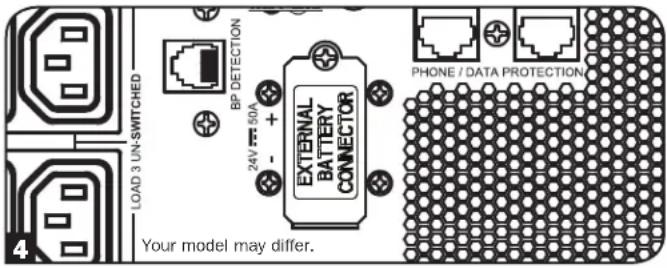
text_image
LOAD 3 UN-SWITCHED RP DETECTION 24V F=50A EXTERNAL BATTERY CONNECTOR PHONE / DATA PROTECTION Your model may differ.IMPORTANT! In order for the runtime-remaining LCD and the software information screens to accurately predict runtime with external battery packs connected, you must configure any connected packs by following the instructions under the Configuring External Battery Packs section under Operations.
CAUTION: Do not open or mutilate batteries. Released material is harmful to the skin and eyes. It may be toxic. The following precautions should be observed when working on batteries: Determine if the battery is inadvertently grounded. If inadvertently grounded, remove the source from ground connection. Contact with any part of a grounded battery can result in electrical shock. The likelihood of such a shock can be reduced if grounds are removed during installation and maintenance. (This is applicable to equipment and remote battery supplies that do not have a grounded supply circuit.)
Troubleshooting and Event Log
See the chart below for explanation of UPS faults and warnings that can be accessed via the Event Log feature via the LCD screen or PowerAlert software, as well as suggested solutions for each fault/warning.
| Fault/Alarm | LCD Header Message LCD | Screen Message | LCD Event Log Display (Event Type with Date/Time Stamp) | Fault Or Alarm? | Additional Comments |
| UPS Internal Errors/Faults: | |||||
| BUS Start Voltage Low Inverter Error 1 | Inverter error. Restart UPS. If issue persists, contact Tripp Lite. | mm/dd/yyyy Inv Err 1 hh:mm UPS fault | |||
| Bus Over Voltage Inverter Error 2 | Inverter error. Restart UPS. If issue persists, contact Tripp Lite. | mm/dd/yyyy Inv Err 2 hh:mm UPS fault | |||
| Bus Under Voltage Inverter Error 3 | Inverter error. Restart UPS. If issue persists, contact Tripp Lite. | mm/dd/yyyy Inv Err 3 hh:mm UPS fault | |||
| Bus Voltage Unbalance Inverter Error 4 | Inverter error. Restart UPS. If issue persists, contact Tripp Lite. | mm/dd/yyyy Inv Err 4 hh:mm UPS fault | |||
| Inverter Soft Start Failed Inverter Error 5 | Inverter error. Restart UPS. If issue persists, contact Tripp Lite. | mm/dd/yyyy Inv Err 5 hh:mm UPS fault | |||
| Inverter Over Voltage Inverter Error 6 | Inverter error. Restart UPS. If issue persists, contact Tripp Lite. | mm/dd/yyyy Inv Err 6 hh:mm UPS fault | |||
| Inverter Under Voltage Inverter Error 7 | Inverter error. Restart UPS. If issue persists, contact Tripp Lite. | mm/dd/yyyy Inv Err 7 hh:mm UPS fault | |||
| Inverter Short Circuit Inverter Error 8 | Inverter output short. Remove the source of short circuit from UPS output. | mm/dd/yyyy Inv Err 8 hh:mm UPS fault | |||
| Battery/Charger Related Errors/Faults: | |||||
| Charger Failure Charger | Failure | If issue persists, contact Tripp Lite. | mm/dd/yyyy Chrg Err 1 hh:mm Warning | Charger is not working. No charge current. | |
| Over Charge | Over Charge | If issue persists, contact Tripp Lite. | mm/dd/yyyy Chrg Err 2 hh:mm Warning | Charger is working but charge voltage is too high. | |
| Battery Over Voltage | Batt. Over Voltage | Check battery type used. If issue persists, contact Tripp Lite. | mm/dd/yyyy Batt Err 1 hh:mmNote: If the UPS shuts down from Batt Err 1, another event, “Batt Err 1 SD”, Is also logged on the event log screen. | UPS fault | |
| Battery Under Voltage | Batt. Under Voltage | Check battery type used. If issue persists, contact Tripp Lite. | mm/dd/yyyy Batt Err 2 hh:mmNote: If the UPS shuts down from Batt Err 2, another event, “Batt Err 2 SD”, Is also logged on the event log screen. | UPS fault | |
| Bad Battery | Bad Battery Restart UPS. If issue persists, contact Tripp Lite. | mm/dd/yyyy Batt Err 3 hh:mmNote: If the UPS shuts down from Batt Err 3, another event, “Batt Err 3 SD”, is also logged on the event log screen. | Warning | ||
| Low Battery | Low Battery Save your data before UPS shuts down. | mm/dd/yyyy Low Batt hh:mmNote: If the UPS shuts down from Low Batt, another event, “Low Batt SD”, is also logged on the event log screen. | Warning | ||
| Internal Battery Age Alert | Battery-Age Alert | Internal battery may need replacement. | mm/dd/yyyy Batt Alert 1 hh:mm | Warning | |
| External Smart Battery Age Alert | Battery-Age Alert | External Smart battery: {SerialNumber} may need replacement. | mm/dd/yyyy Batt Alert 2 hh:mm | Warning | |
| External Non-Smart Battery Age Alert | Battery-Age Alert | External battery may need replacement. | mm/dd/yyyy Batt Alert 3 hh:mm | Warning | |
| Smart Batt Changed Smart Batt Changed | The number of Smart battery packs are changed at month/ date/year hr: min. Runtime has been adjusted. If this change is unexpected, please check smart battery communications. | mm/dd/yyyy S BP Changed hh:mm | Warning | ||
Troubleshooting and Event Log
| Fault/Alarm | LCD Header Message LCD | Screen Message | LCD Event Log Display (Event Type with Date/Time Stamp) | Fault Or Alarm? Additional Comments | |
| Load/Temperature Related Errors/Faults: | |||||
| Over Temperature Fault Over Temp Fault | Over Temp Fault | Check UPS ventilation and fan. If issue persists, contact Tripp Lite. | mm/dd/yyyy OverTempFault hh:mmNote: mm/dd/yyyy OverTemp SD hh:mm is also logged when the unit actually shuts down after being in fault mode. | UPS fault | At the time the over temperature threshold is reached, the OverTempFault event will be triggered and if AC is available, then depending on the fault mode setting, the unit will either transfer to Bypass mode or Standby mode. If AC is unavailable, the unit will transition to fault mode with output turned off, then shuts down. |
| Over Temperature (warning only) | Over Temp Check | Check UPS ventilation and fan. If issue persists, contact Tripp Lite. | mm/dd/yyyy OverTempAlert hh:mm | Warning This is a warning threshold only. The unit should not take action based on this event other than to display and log the warning. | |
| Overload Fault Overload Reduce connected load. Restart UPS. | mm/dd/yyyy Overload hh:mm (mm/dd/yyyy Overload SD hh:mm is also logged when the unit actually shuts down after being in fault mode) | UPS fault | At the time the overload fault is triggered, the Overload event will be logged and if AC is available, then depending on the fault mode setting, the unit will either transfer to Bypass mode or Standby mode. If AC is unavailable, the unit will transition to fault mode with output turned off, then shuts down. UPS will not intentionally shut down due to overload in this mode regardless how high the load is.Note: The circuit breaker may trip due to the overload. | ||
| Overload Warning Overload Alarm | Reduce connected load. mm/dd/yyyy Overload ALM hh:mm Warning Overload warning is triggered when the load level is between 100% to 105% or when load level reaches the preconfigured overload warning level. | ||||
| Other Warnings and Events: | |||||
| EPO Active EPO Active | Check EPO switch. If issue persists, contact Tripp Lite. | mm/dd/yyyy EPO SD hh:mm | Warning | ||
| Bypass Out of Range | Bypass Range Error | Check AC input volt. and freq. If issue persists, contact Tripp Lite. | mm/dd/yyyy Bypass Err 1 hh:mm Warning AC input voltage might be meeting the preconfigured bypass range requirement, see Operations section for more information. | ||
| Bypass Frequency Unstable | Bypass Freq. Error | Check AC input freq. If issue persists, contact Tripp Lite. | mm/dd/yyyy Bypass Err 2 hh:mm Warning | ||
| On Battery | N/A | N/A | mm/dd/yyyy On Batt hh:mmNote: If the UPS shuts down in Battery Mode based on preconfigured delay, "On Battery" will be replaced with "Timed SD", and logged as another event. | Normal | |
| AC Failure | N/A | N/A | mm/dd/yyyy AC Failure hh:mmNote: If valid AC returns, "On Utility" is logged as another event. | Normal | |
Internal Battery Replacement
Battery Replacement Door: Under normal conditions, the original battery in your UPS will last several years. Battery replacement should be performed only by qualified service personnel. Refer to "Battery Warnings" in the Safety section. If you require a replacement battery, you can find it at tripplite.com/support/battery/index.cfm. See the chart below to find the right replacement battery for your UPS system:
| UPS Model Replacement Battery Cartridge | |
| SUINT1000LCD2U RBC24S | |
| SUINT1500LCD2U RBC36S | |
| SUINT2200LCD2U RBC48S | |
| SUINT3000LCD2U / SU3000LCD2UHV RBC72S |
See the following diagrams for battery removal and installation procedures.
All Models
Note: The SUINT1000LCD2U is shown, but the procedure is the same for the other units.
1 Remove the four front screws from the front bezel and take it off.
natural_image
Technical line drawing of a server rack with ventilation fan and cooling unit (no text or symbols)3 Open the front plate. Disconnect battery power cable and communication cable.
natural_image
Diagram of a computer drive showing internal components and airflow direction (no text or symbols)5 Install new battery pack into the UPS in the same position as the original pack.
natural_image
Technical line drawing of a mechanical assembly with a black arrow indicating direction (no text or symbols present)2 Loosen the two screws securing the front plate.
natural_image
Technical line drawing of a computer tower with ventilation fan and drive slots (no text or symbols)4 Remove old battery pack.
natural_image
Technical line drawing of a mechanical assembly with a downward arrow indicating motion (no text or symbols present)6 Reconnect battery power cable and communication cable. Close the front plate.
natural_image
Diagram of a computer drive showing internal components and airflow direction (no text or symbols)Internal Battery Replacement
7 Tighten the two screws to secure the front plate.
natural_image
Technical line drawing of a computer tower with fan and drive components (no text or symbols)8 Replace the four front screws to secure the bezel.
natural_image
Technical line drawing of a server rack with ventilation duct and fan (no text or symbols)Storage and Service
Storage
First turn your UPS OFF: press the "OFF" switch to turn power off at the UPS outlets, then disconnect the power cord from the wall outlet. Next, disconnect all equipment to avoid battery drain. If you plan on storing your UPS for an extended period of time, fully recharge the UPS batteries once every three months by plugging the UPS into a live AC outlet and letting the UPS charge for 4-6 hours. If you leave your UPS batteries discharged for an extended period of time, they may suffer permanent loss of capacity.
Service
A variety of Extended Warranty and On-Site Service Programs are also available from Tripp Lite. For more information on service, visit tripplite.com/support. Before returning your product for service, follow these steps:
- Review the installation and operation procedures in this manual to ensure that the service problem does not originate from a misreading of the instructions.
- If the problem continues, do not contact or return the product to the dealer. Instead, visit tripplite.com/support.
- If the problem requires service, visit tripplite.com/support and click the Product Returns link. From here you can request a Returned Material Authorization (RMA) number, which is required for service. This simple on-line form will ask for your unit's model and serial numbers, along with other general purchaser information. The RMA number, along with shipping instructions will be emailed to you. Any damages (direct, indirect, special or consequential) to the product incurred during shipment to Tripp Lite or an authorized Tripp Lite service center is not covered under warranty. Products shipped to Tripp Lite or an authorized Tripp Lite service center must have transportation charges prepaid. Mark the RMA number on the outside of the package. If the product is within its warranty period, enclose a copy of your sales receipt. Return the product for service using an insured carrier to the address given to you when you request the RMA.
Product Registration and Regulatory Compliance
Visit tripplite.com/warranty today to register your new Tripp Lite product. You'll be automatically entered into a drawing for a chance to win a FREE Tripp Lite product!* * No purchase necessary. Void where prohibited. Some restrictions apply. See website for details.
Regulatory Compliance Identification Numbers:
For the purpose of regulatory compliance certifications and identification, your Tripp Lite product has been assigned a unique series number. The series number can be found on the product nameplate label, along with all required approval markings and information. When requesting compliance information for this product, always refer to the series number. The series number should not be confused with the marketing name or model number of the product.
FCC Specifications for Models with FCC Class A Approval:
This device complies with part 15 of the FCC Rules. Operation is subject to the following two conditions: (1) This device may not cause harmful interference, and (2) this device must accept any interference received, including interference that may cause undesired operation.
Note: This equipment has been tested and found to comply with the limits for a Class A digital device, pursuant to part 15 of the FCC Rules. These limits are designed to provide reasonable protection against harmful interference when the equipment is operated in a commercial environment. This equipment generates, uses, and can radiate radio frequency energy and, if not installed and used in accordance with the instruction manual, may cause harmful interference to radio communications. Operation of this equipment in a residential area is likely to cause harmful interference in which case the user will be required to correct the interference at his own expense. The user must use shielded cables and connectors with this equipment. Any changes or modifications to this equipment not expressly approved by Tripp Lite could void the user's authority to operate this equipment.
EMC Specifications for Models with EMC Category C2 Approval (Select Models):
WARNING: This is a category C2 UPS product. In a residential environment, this product may cause radio interference, in which case the user may be required to take additional measures.
WEEE Compliance Information for Tripp Lite Customers and Recyclers (European Union)

Under the Waste Electrical and Electronic Equipment (WEEE) Directive and implementing regulations, when customers buy new electrical and electronic equipment from Tripp Lite they are entitled to:
- Send old equipment for recycling on a one-for-one, like-for-like basis (this varies depending on the country)
- Send the new equipment back for recycling when this ultimately becomes waste
FCC Part 68 Notice (United States Only)
If your Modem/Fax Protection causes harm to the telephone network, the telephone company may temporarily discontinue your service. If possible, they will notify you in advance. If advance notice isn't practical, you will be notified as soon as possible. You will be advised of your right to file a complaint with the FCC. Your telephone company may make changes in its facilities, equipment, operations or procedures that could affect the proper operation of your equipment. If it does, you will be given advance notice to give you an opportunity to maintain uninterrupted service. If you experience trouble with this equipment's Modem/Fax Protection, please visit tripplite.com/support for repair/warranty information. The telephone company may ask you to disconnect this equipment from the network until the problem has been corrected or you are sure the equipment is not malfunctioning. There are no repairs that can be made by the customer to the Modem/Fax Protection. This equipment may not be used on coin service provided by the telephone company. Connection to party lines is subject to state tariffs. (Contact your state public utility commission or corporation commission for information.)
UPS and Battery Recycling

Please recycle Tripp Lite Products. The batteries used in Tripp Lite products are sealed Lead-Acid batteries. These batteries are highly recyclable. Please refer to your local codes for disposal requirements.
You can call Tripp Lite for recycling info at +1.773.869.1234.
You can go the Tripp Lite Website for up-to-date information on recycling the batteries or any Tripp Lite product. Please follow this link: tripplite.com/en/support/recycling-program.cfm
Tripp Lite has a policy of continuous improvement. Specifications are subject to change without notice. Photos and illustrations may differ slightly from actual products.

text_image
TRIPP·LITE
1111 W. 35th Street, Chicago, IL 60609 USA • www.tripplite.com/support
1111 W. 35th Street, Chicago, IL 60609 USA • tripplite.com/support
natural_image
Line drawing of a server rack unit with ventilation grilles and control panel (no text or symbols)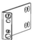
natural_image
Technical line drawing of two parallel metal beams with mounting feet (no text or symbols)text_image
Load Protected (Potency) Control A0 5 SD 1 3.5mA 500V 2.5mA 500V E D F 3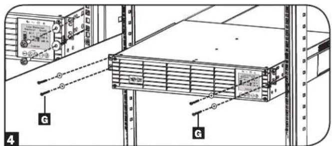
text_image
Technical diagram showing server rack with labeled components and connection points, including a zoomed-in view of the rack.natural_image
Technical line drawing of mechanical components with no visible text or symbols
text_image
Load Protection 80 V 8 Min 30 V 50 V 80 V Enabling 20 V 40 V 60 V 70 V 80 V 90 V 100 V 110 V 120 V 130 V 140 V 150 V 160 V 170 V 180 V 190 V 200 V 210 V 220 V 230 V 240 V 250 V 260 V 270 V 280 V 290 V 300 V 310 V 320 V 330 V 340 V 350 V 360 V 370 V 380 V 390 V 400 V 410 V 420 V 430 V 440 V 450 V 460 V 470 V 480 V 490 V 500 V| Modelo de UPS | SUINT1000LCD2U | SUINT1500LCD2U | SUINT2200 | SUINT3000LCD2U / SU3000LCD2UHV |
| Dimensiones del UPS (Al x An x Pr) | 8.6 x 43.8 x 39.6 cm | 8.6 x 43.8 x 49.6 cm | 8.6 x 43.8 x 49.6 cm | 8.6 x 43.8 x 61.6 cm |
natural_image
Technical line drawing of a server rack with ventilation fan and cooling unit (no text or symbols)3 Abra la placa frontal.
natural_image
Diagram of a computer tower with ventilation fan and drive slots, showing an arrow indicating a component (no text or symbols present)natural_image
Technical diagram of an electronic device showing internal components and a rotating arrow indicating motion (no text or symbols present)text_image
Technical diagram of a computer drive with labeled parts and directional arrows indicating assembly or movement.natural_image
Technical line drawing of a server rack with fan and drive components (no text or symbols)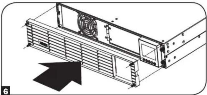
natural_image
Technical line drawing of a mechanical device with fan and mounting bracket (no text or symbols)text_image
Language ► English Back Next ESC SETUPtext_image
Password Setup Back Select Next ESC SETUP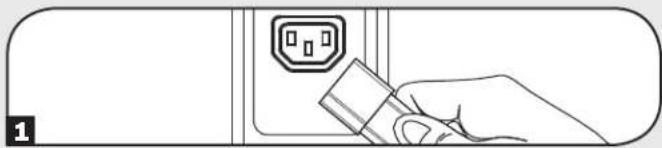
natural_image
Line drawing of a hand inserting a plug into an electrical outlet (no text or symbols)text_image
Power Strategy ▶ Auto-Adaptive Max Efficiency Max @quality Freq. Regulation Freq. Conv. To 60Hz Freq. Conv. To 50Hz Back Select Applytext_image
Audible Alarm ▶ Enabled Disabled Back Select Apply ESC SETUP9 Encienda su UPS
text_image
LCD2U 1 2 9 3 8 2 7 WARNING: MHz battery systems ON AVERTISSEMENT. BATTERY SYSTEMS AND EQUIPMENT. 4 5 6SUINT3000LCD2U
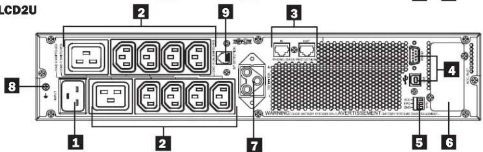
text_image
CD2U 1 2 3 4 5 6 7 8 9 WARNING: TIME ACTION SYSTEM ON/OVERTISSEMENT. DATA SYSTEM ON/OVERTISMENT.SU3000LCD2UHV
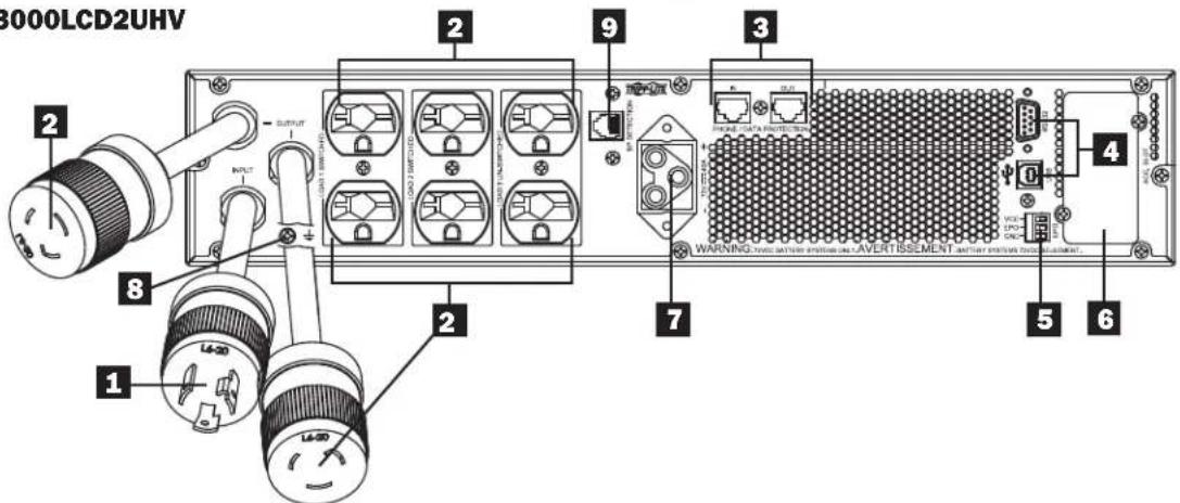
text_image
3000LCD2UHV 1 2 8 1 2 INPUT OUTPUT OUTPUT OUTPUT OUTPUT OUTPUT OUTPUT OUTPUT OUTPUT OUTPUT OUTPUT OUTPUT OUTPUT OUTPUT OUTPUT OUTPUT OUTPUT OUTPUT OUTPUT OUTPUT OUTPUT OUTPUT OUTPUT OUTPUT OUTPUT OUTPUT OUTPUT OUTPUT OUTPUT OUTPUT OUTPUT OUTPUT OUTPUT OUTPUT OUTPUT OUTPUT OUTPUT OUTPUT OUTPUT OUTPUT OUTPUT OUTPUT OUTPUT OUTPUT OUTPUT OUTPUT OUTPUT OUTPUT OUTPUT OUTPUT OUTPUT AVERAGE OUTPUT AVERTISSEMENT ANTERIOR OUTPUT AVERAGE OUTPUT AVERTISSEMENT AVERTISSEMENT AVERTISSEMENT AVERTISSEMENT AVERTISSEMENT AVERTISSEMENT AVERTISSEMENT AVERTISSEMENT AVERTISSEMENT AVERTISSEMENT AVERTISSEMENT AVERTISSEMENT AVERTISSEMENT AVERTISSEMENT AVERTISSEMENT AVERTISSEMENT AVERTISSEMENT AVERTISSEMENT AVERTISSEMENT AVERTISSEMENT AVERTISSEMT AVERTISSEMT AVERTISSEMT AVERTISSEMT AVERTISSEMT AVERTISSEMT AVERTISSEMT AVERTISSEMT AVERTISSEMT AVERTISSEMT AVERTISSEMT AVERTISSEMT AVERTISSEMT AVERTISSEMT AVERTISSEMT AVERTISSEMT AVERTISSEMT AVERTISSEMT AVERTISSEMT AVERTISSEMT AVERTISSEMSA TAVES SAVES SAVES SAVES SAVES SAVES SAVES SAVES SAVES SAVES SAVES SAVES SAVES SAVES SAVES SAVES SAVES SAVES SAVES SAVES SAVES SAVES SAVES SAVES SAVES SAVES SAVES SAVES SAVES SAVES SAVES SAVES SAVES SAVES SSVS SSVS SSVS SSVS SSVS SSVS SSVS SSVS SSVS SSVS SSVS SSVS SSVS SSVS SSVS SSVS SSVS SSVS SSVS SSVS SSVS SSVS SSVS SSVS SSVS SSVS SSVS SSVS SSVS SSVS SSVS SSVS SSVS SSVSOperaciones
text_image
Battery ► External Batt Batt Age Alert Back Select NextOperaciones
Note Presently configured via UPS on 04/07/2014 Press Next to change
Back Next
External Batt
Configure via UPS PC Configured External Batt
Back Select Next
Configure via UPS
SMART BPs beyond qty b must be configured as NONSMART.
Back Next
Change accepted. For true capacity and runtime reporting, verify connected BPs match configuration
Back Next
Configure via UPS entered.
Back Next
Press Next to enter Battery Installed Date for manually added battery packs.
Back Next
natural_image
Technical line drawing of a server rack with ventilation duct and fan (no text or symbols)natural_image
Diagram of a computer drive showing internal components and directional arrows indicating motion (no text or symbols)natural_image
Technical line drawing of a mechanical assembly with a black arrow indicating direction (no text or symbols present)natural_image
Diagram of a computer tower with ventilation slots and a monitor, showing a directional arrow (no text or symbols present)natural_image
Technical line drawing of a mechanical assembly with a downward arrow indicating motion (no text or symbols present)natural_image
Diagram of a computer drive showing internal components and airflow direction (no text or symbols)natural_image
Technical line drawing of a computer drive chassis with fan and buttons (no text or symbols)natural_image
Technical line drawing of a server rack with fan and ventilation duct (no text or symbols)1111 W. 35th Street, Chicago, IL 60609 USA • tripplite.com/support
1111 W. 35th Street, Chicago, IL 60609 USA • tripplite.com/support
natural_image
Line drawing of a server rack unit with ventilation grilles and indicator lights (no text or symbols)

natural_image
Technical line drawing of two mechanical components with mounting brackets (no text or symbols)text_image
Technical diagram showing server rack with labeled components and connection points, including a control panel and indicator lights.natural_image
Technical line drawing of mechanical components with no visible text or symbols
text_image
Load Protected 40 Ω 2Ω 8Ω 1Ω 50 Ω 2Ω LED V4 Coatings -30 +30 -30 +30 -30natural_image
Technical line drawing of a server rack with ventilation ducts and fan (no text or symbols)3 Ouvrez la plaque avant.
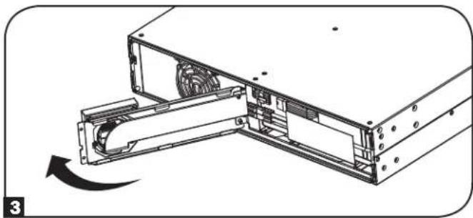
natural_image
Technical diagram of a computer drive assembly showing internal components and a rotating arrow (no text or symbols)natural_image
Technical line drawing of a computer tower with fan and drive components (no text or symbols)natural_image
Technical line drawing of a computer tower with ventilation fan and drive slots (no text or symbols)4 Connectez le câble de communication des BATTERIES INTELLIGENTES. Fermez la plaque avant.
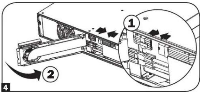
text_image
Technical diagram showing a device's internal structure with numbered annotations and directional arrows indicating flow or movement.natural_image
Technical line drawing of a mechanical device with fan and housing (no text or symbols)REMARQUE CONCERNANT LA CONFIGURATION DE LA BATTERIE EXTERNE
text_image
Language ► English Back Next ESC SETUPtext_image
Password Setup Back Select Next ESC SETUP
natural_image
Line drawing of a hand inserting a plug into an electrical outlet (no text or symbols)text_image
Power Strategy ▶ Auto-Adaptive Max Efficiency Max Quality Freq. Regulation Freq. Conv. To 60Hz Freq. Conv. To 50Hz Back Select Applytext_image
Audible Alarm ▶ Enabled Disabled Back Select Apply ESC SETUPNote Presently configured via UPS on 04/07/2014 Press Next to change
Back Next
External Batt
Configure via UPS PC Configured External Batt
Back Select Next
Configure via UPS
SMART BPs beyond qty b must be configured as NONSMART.
Back Next
Change accepted. For true capacity and runtime reporting, verify connected BPs match configuration
Back Next
Configure via UPS entered.
Back Next
Press Next to enter Battery Installed Date for manually added battery packs.
Back Next
Connexions facultatives
natural_image
Technical line drawing of a server rack with ventilation duct and fan (no text or symbols)natural_image
Diagram of a computer drive showing internal components and airflow direction (no text or symbols)natural_image
Technical line drawing of a server rack with an arrow indicating compression or disassembly (no text or symbols present)natural_image
Technical line drawing of a computer tower with ventilation fan and drive slots (no text or symbols)natural_image
Technical line drawing of a mechanical assembly with a downward arrow indicating motion (no text or symbols present)natural_image
Diagram of a computer drive showing internal components and airflow direction (no text or symbols)natural_image
Technical line drawing of a server rack with fan and drive components (no text or symbols)natural_image
Technical line drawing of a server rack with ventilation duct and mounting bracket (no text or symbols)1111 W. 35th Street, Chicago, IL 60609 USA • tripplite.com/support
1111 W. 35th Street, Chicago, IL 60609 USA • tripplite.com/support
natural_image
Line drawing of a server rack unit with ventilation grilles and control panel (no text or symbols)natural_image
Technical line drawing of two parallel metal frame structures with mounting brackets (no text or symbols)text_image
Load Protected Battery1 Load 0.5Ω 300 Ω 200 Ω A=1 kV Enable E D F 3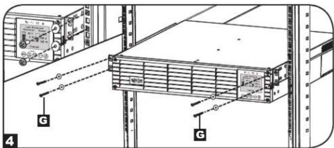
text_image
Technical diagram showing server rack with labeled components and connection points, including a monitor and indicator lights.natural_image
Technical line drawing of mechanical components with no visible text or symbols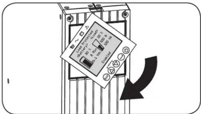
text_image
LED Protection Battery 2.5V 6.0V 4.0V 3.0V 2.0V LED LED LED LED LED LED LED LEDnatural_image
Technical line drawing of a server rack with ventilation duct and fan (no text or symbols)natural_image
Diagram of a computer tower with ventilation fan and drive slots, showing a mechanical assembly without any text or symbols.natural_image
Technical diagram of a computer drive assembly showing internal components and a rotating arrow (no text or symbols)text_image
Technical diagram of a computer rack with labeled parts and directional arrows indicating movement or assembly.natural_image
Technical line drawing of a computer drive with fan and ports (no text or symbols)natural_image
Technical line drawing of a mechanical device with fan and housing (no text or symbols)text_image
Language ► English Back Next SETUP ESCtext_image
Password Setup Back Select Next ESC SETUP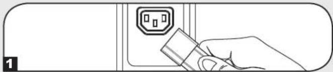
natural_image
Line drawing of a hand inserting a plug into an electrical outlet (no text or symbols)text_image
Power Strategy ▶ Auto-Adaptive Max Efficiency Max Quality Freq. Regulation Freq. Conv. To 60Hz Freq. Conv. To 50Hz Back Select Applytext_image
Audible Alarm ▶ Enabled Disabled Back Select Apply ESC SETUP9 Включите ИБП
text_image
Battery ► External Batt Batt Age Alert Back Select NextЭксплуатация
Note Presently configured via UPS on 04/07/2014 Press Next to change
Back Next
External Batt
Configure via UPS PC Configured External Batt
Back Select Next
Configure via UPS
SMART BPs beyond qty b must be configured as NONSMART.
Back Next
Change accepted. For true capacity and runtime reporting, verify connected BPs match configuration
Back Next
Configure via UPS entered.
Back Next
Press Next to enter Battery Installed Date for manually added battery packs.
Back Next
natural_image
Technical line drawing of a server rack with ventilation duct and cooling panel (no text or symbols)natural_image
Diagram of a computer drive showing internal components and directional arrows indicating motion (no text or symbols)natural_image
Technical illustration of a mechanical assembly with a black arrow indicating direction (no text or symbols present)natural_image
Technical line drawing of a computer tower with ventilation fan and drive slots (no text or symbols)4 Извлеките старый блок батарей.
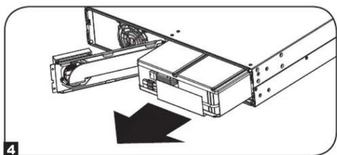
natural_image
Technical illustration of a mechanical assembly with a downward arrow indicating motion (no text or symbols present)natural_image
Diagram of a computer drive showing internal components and airflow direction (no text or symbols)natural_image
Technical line drawing of a computer drive chassis with fan and buttons (no text or symbols)natural_image
Technical line drawing of a mechanical device with fan and housing (no text or symbols)1111 W. 35th Street, Chicago, IL 60609 USA • tripplite.com/support
Bedienungsanleitung
SmartOnline®
Manufacturing Excellence.
1111 W. 35th Street, Chicago, IL 60609 USA • tripplite.com/support
natural_image
Line drawing of a server rack unit with ventilation grilles and control panel (no text or symbols)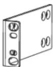
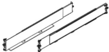
natural_image
Technical line drawing of two parallel metal beams with mounting feet (no text or symbols)text_image
Technical diagram showing server rack with labeled components and connection points, including a control panel and G-bracing indicator.2-Pfosten-Montage
natural_image
Technical line drawing of mechanical components with no visible text or symbols
text_image
Load: Packed 40Ω 8.5Ω 30Ω 1.5Ω LED V4 LED V3 LED V2 LED V1 LED V0 LED V-1 LED V-2 LED V-3 LED V-4 LED V5 LED V6 LED V7 LED V8 LED V9 LED V10 LED V11 LED V12 LED V13 LED V14 LED V15 LED V16 LED V17 LED V18 LED V19 LED V20 LED V21 LED V22 LED V23 LED V24 LED V25 LED V26 LED V27 LED V28 LED V29 LED V30 LED V31 LED V32 LED V33 LED V34 LED V35 LED V36 LED V37 LED V38 LED V39 LED V40| USV-Modell SUINT | 1000LCD2U SUINT150 | 0LCD2U SUINT2200LCD2U SUINT3000LCD2U / SU3000LCD2UHV | |
| USV-Abmessungen (H x B x T) | 8,6 x 43,8 x 39,6 cm | 8,6 x 43,8 x 49,6 cm 8,6 x 43,8 x 49,6 cm 8,6 x 43,8 x 61,6 cm | |
natural_image
Technical line drawing of a server rack with ventilation duct and fan (no text or symbols)natural_image
Technical illustration of a computer drive assembly with an arrow indicating rotation (no text or symbols present)natural_image
Technical line drawing of a computer tower with ventilation fan and drive slots (no text or symbols)natural_image
Technical line drawing of a computer tower with ventilation slots and a scroll wheel (no text or symbols)text_image
Technical diagram showing a device's internal structure with numbered annotations and directional arrows indicating flow or movement.natural_image
Technical line drawing of a mechanical device with fan and housing (no text or symbols)HINWEIS ZUR EXTERNEN BATTERIEKONFIGURATION
text_image
Language ► English Back Next ESC SETUPtext_image
Password Setup Back Select Next ESC SETUP
natural_image
Line drawing of a hand inserting a plug into an electrical outlet (no text or symbols)text_image
Power Strategy ▶ Auto-Adaptive Max Efficiency Max Quality Freq. Regulation Freq. Conv. To 60Hz Freq. Conv. To 50Hz Back Select Applytext_image
Audible Alarm ▶ Enabled Disabled Back Select Apply ESC SETUPtext_image
Battery ► External Batt Batt Age Alert Back Select NextBetrieb
Change accepted. For true capacity and runtime reporting, verify connected BPs match configuration
Back Next
Note Presently configured via UPS on 04/07/2014 Press Next to change
Back Next
External Batt
Configure via UPS PC Configured External Batt
Back Select Next
Configure via UPS
SMART BPs beyond qty b must be configured as NONSMART.
Back Next
Configure via UPS
S+N Pack
0 0 BP48V24-2U 0 0 BP48V60RT-3U 0 0 BP484V24-2US
Back Select Next
Configure via UPS entered.
Back Next
Configure via UPS
Press Next to enter Battery Installed Date for manually added battery packs.
Back Next
Optionale Anschlüsse
Optionale Anschlüsse
Optionale Anschlüsse
natural_image
Technical line drawing of a server rack with ventilation duct and cooling panel (no text or symbols)natural_image
Diagram of a computer tower with ventilation fan and drive slots, showing a mechanical assembly without any text or symbols.natural_image
Diagram of a computer drive showing internal components and airflow direction (no text or symbols)natural_image
Technical line drawing of a mechanical assembly with a downward arrow indicating motion (no text or symbols present)natural_image
Technical line drawing of a server rack with a black arrow indicating motion (no text or symbols)natural_image
Diagram of a computer drive showing internal components and airflow direction (no text or symbols)Interner Batteriewechsel
natural_image
Technical line drawing of a computer tower with fan and drive components (no text or symbols)natural_image
Technical line drawing of a server rack with fan and ventilation duct (no text or symbols)Manufacturing Excellence.
1111 W. 35th Street, Chicago, IL 60609 USA • tripplite.com/support