SmartPro SMC10002URM - Inverter Tripp Lite - Free user manual and instructions
Find the device manual for free SmartPro SMC10002URM Tripp Lite in PDF.

User questions about SmartPro SMC10002URM Tripp Lite
0 question about this device. Answer the ones you know or ask your own.
Ask a new question about this device
Download the instructions for your Inverter in PDF format for free! Find your manual SmartPro SMC10002URM - Tripp Lite and take your electronic device back in hand. On this page are published all the documents necessary for the use of your device. SmartPro SMC10002URM by Tripp Lite.
USER MANUAL SmartPro SMC10002URM Tripp Lite
Intelligent, Line-Interactive UPS Systems
120V Sine Wave Output • 1,000VA—1,500VA
SMC10002URM
(Series No. AGSM8267)
SMC15002URM
(Series No. AG-0007)
Not suitable for mobile applications.
natural_image
Line drawing of a computer drive unit with ventilation grilles and a digital display (no text or symbols)Important Safety Instructions 2
Mounting
4
Quick Installation 6
Optional Installation 7
Basic Operation 8
Storage and Service 16
Battery Replacement 17
Product Registration 19
Regulatory Compliance 19
Español
20
Français
39
PROTECT YOUR INVESTMENT!
Register your product for quicker service and ultimate peace of mind. You could also win an ISOBAR6ULTRA surge protector—a \$50 value!
www.tripplite.com/warranty

text_image
TRIPP·LITE
Manufacturing Excellence.
1111 W. 35th Street, Chicago, IL 60609 USA • www.tripplite.com/support
Copyright © 2014 Tripp Lite. All rights reserved. SmartPro® is a registered trademark of Tripp Lite.
Important Safety Instructions

SAVE THESE INSTRUCTIONS
This manual contains important instructions that should be followed during the installation, operation and storage of this product. Failure to heed these warnings may affect the warranty.
UPS Location Warnings
- Use caution when lifting the UPS. Because of the considerable weight of all rackmount UPS systems, at least two people should assist in lifting and installing them.
• Install the UPS indoors, away from excess moisture or heat, dust or direct sunlight. - For best performance, the ambient temperature near the UPS should be between 0^ C and 40^ C (between 32^ F and 104^ F).
- Leave adequate space around all sides of the UPS for proper ventilation. Do not obstruct its vents or fan openings.
- When mounting the UPS system in a tower orientation, make sure the LCD Screen panel is at the top of the UPS, not at the bottom.
- Do not mount unit with its front or rear panel facing down (at any angle). Mounting in this manner may eventually cause product damage not covered under warranty.
UPS Connection Warnings
- The UPS contains its own energy source (battery). The output terminals may be live even when the UPS is not connected to an AC supply.
- Connect the UPS to a properly grounded AC power outlet. Do not modify the UPS's plug in a way that would eliminate the UPS's connection to ground. Do not use adapters that eliminate the UPS's connection to ground.
- Do not plug the UPS into itself; this will damage the UPS and void your warranty.
- If you are connecting the UPS to a motor-powered AC generator, the generator must provide filtered, frequency-regulated computer-grade output. Connecting the UPS to a generator will void its Ultimate Lifetime Insurance.
Equipment Connection Warnings
- Use of this equipment in life support applications where failure of this equipment can reasonably be expected to cause the failure of the life support equipment or to significantly affect its safety or effectiveness is not recommended. Do not use this equipment in the presence of a flammable anesthetic mixture with air, oxygen or nitrous oxide.
- Do not connect surge suppressors or extension cords to the output of the UPS. This might damage the UPS and may affect the surge suppressor and UPS warranties.
Important Safety Instructions

Battery Warnings
- Batteries can present a risk of electrical shock and burn from high short-circuit current. Observe proper precautions. Do not dispose of the batteries in a fire. Do not open the UPS or batteries. Do not short or bridge the battery terminals with any object. Unplug and turn off the UPS before performing battery replacement. Use tools with insulated handles. There are no user-serviceable parts inside the UPS. Battery replacement should be performed only by authorized service personnel using the same number and type of batteries (Sealed Lead-Acid). Tripp Lite offers a complete line of UPS System Replacement Battery Cartridges (R.B.C.). Visit Tripp Lite on the Web at www.tripplite.com/support/battery/index.cfm to locate the specific replacement battery for your UPS. The RBC Type can also be found on the label affixed to the Battery Retention Plate.
- During hot-swap battery replacement, the UPS will not provide backup power in the event of a blackout or other power interruptions.
- Do not operate the UPS without batteries.

Pb
UPS and Battery Recycling
Please recycle Tripp Lite Products. The batteries used in Tripp Lite products are sealed Lead-Acid batteries. These batteries are highly recyclable. Please refer to your local codes for disposal requirements.
You can call Tripp Lite for recycling info at 1-773-869-1234.
You can go the Tripp Lite Website for up-to-date information on recycling the batteries or any Tripp Lite product. Please follow this link: http://www.triplite.com/support/recycling-program/
Mounting
The user must determine the fitness of hardware and procedures before mounting. If hardware and procedures are not suitable for your application, contact the manufacturer of your rack or rack enclosure. The procedures described in this manual are for common rack and rack enclosure types and may not be appropriate for all applications.
Note: The illustrations may differ from your model.
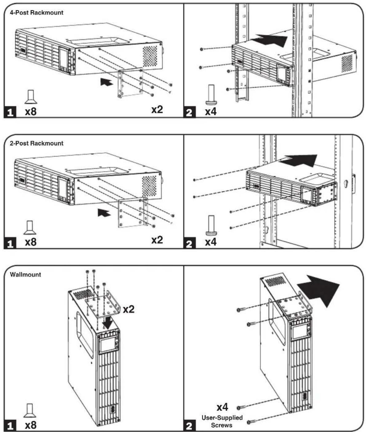
Mounting (Tower)
WARNING: When mounting the UPS system in a tower or wall-mount orientation, make sure the LCD Screen panel is at the top of the UPS, not at the bottom.
Note: To mount the UPS in an upright (tower) position, 2-9USTAND is required (sold separately).
Rotate the LCD Screen panel for easy viewing while the UPS is tower mounted. Insert a small screwdriver or other tool in the slots on either side of the panel. Pop the panel out, rotate it and pop the panel back in place.
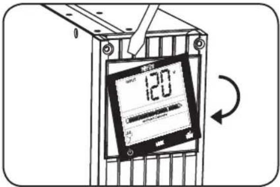
text_image
120° A. 500 A. 500 A. 500Quick Installation
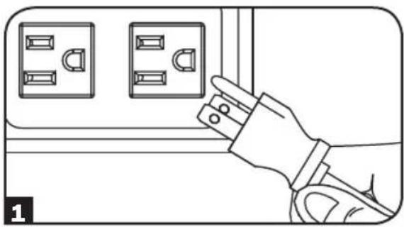
1 Plug the UPS into an outlet on a dedicated circuit.
Note: After you plug the UPS into a live AC outlet, the UPS (in "Standby" mode) will automatically charge its batteries, but will not supply power to its outlets until it is turned ON.
2 Plug your equipment into the UPS.\*
* Your UPS is designed to support only electronic equipment. You will overload the UPS if the total VA ratings for all the equipment you connect exceeds the UPS's Output Capacity. To find your equipment's VA ratings, look on its nameplates. If the equipment is listed in amps, multiply the number of amps by 120 to determine VA. (Example: 1 amp × 120 = 120 VA) If you are unsure if you have overloaded the UPS's outlets, see LOAD icon description in LCD Interface section under Basic Operation.
3 Turn the UPS ON.
Press and hold the 📄 button A for one second. The alarm will beep once briefly.
Note: UPS system will function properly upon initial startup, however, maximum runtime and a successful self-test will only be accessible after it has been charged for 24 hours.
natural_image
Line drawing of a hand inserting a plug into an electrical outlet (no text or symbols)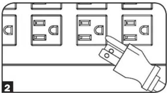
natural_image
Illustration of a hand inserting electrical plug into a panel with multiple socket compartments (no text or symbols)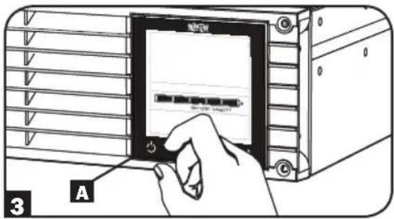
text_image
3 AOptional Installation
These connections are optional. Your UPS will function properly without these connections.
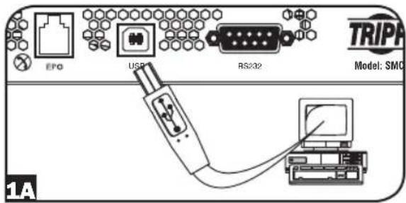
1 USB and RS-232 Serial Communications
Use the included USB cable (see 1A) or user-supplied DB9 serial cable (see 1B) to connect the communication port on your computer to the communication port of your UPS. Install on your computer the Tripp Lite PowerAlert Software appropriate to your computer's operating system.
text_image
EPG USB RS232 TRIPA Model: SMC 1A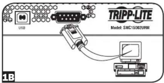
text_image
USB TRIPP-LITE Model: SMC15002URM 1B2 EPO Port Connection
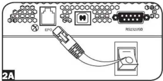
This optional feature is only for those applications which require connection to a facility's Emergency Power Off (EPO) circuit. When the UPS is connected to this circuit, it enables emergency shutdown of the UPS's inverter.
With a user-supplied cable, connect the EPO port of your UPS (see 2A) to a user-supplied normally closed or normally open switch according to the circuit diagram (see 2B). The EPO port is not a phone line surge suppressor; do not connect a phone line to this port.
text_image
EPO RS232USB 2A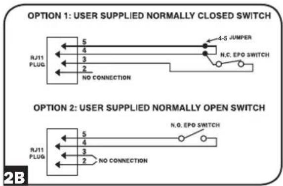
flowchart
graph TD
    A["OPTION 1: USER SUPPLIED NORMALLY CLOSED SWITCH"] --> B["RJ11 PLUG"]
    B --> C["NO CONNECTION"]
    D["OPTION 2: USER SUPPLIED NORMALLY OPEN SWITCH"] --> E["RJ11 PLUG"]
    E --> F["NO CONNECTION"]
    G["4-5 JUMPER"] --> H["N.C. EPO SWITCH"]
    I["5"] --> B
    J["4"] --> B
    K["3"] --> B
    L["2"] --> B
    M["4"] --> E
    N["5"] --> E
    O["4"] --> E
    P["3"] --> E
    Q["2"] --> E
    R["N.O. EPO SWITCH"] --> S["N.O. EPO SWITCH"]
Basic Operation
LCD Interface
text_image
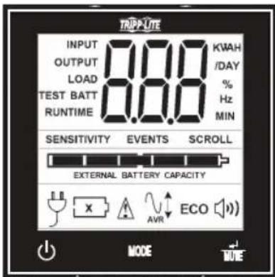
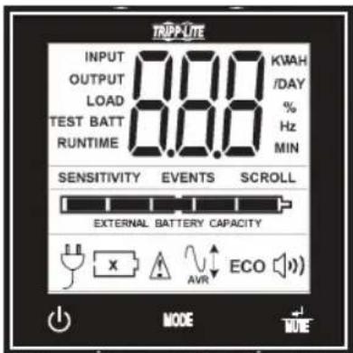
TRIP-UTE INPUT 0.00 KWAH OUTPUT 0.00 /DAY LOAD 0.00 % TEST BATT 0.00 % Hz RUNTIME MIN SENSITIVITY EVENTS SCROLL EXTERNAL BATTERY CAPACITY E C O E X AVR MODE RULENote: This LCD image is shown with all icons illuminated. Under normal conditions, only select icons will be lit.
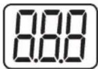
3-Digit Display: This display is generally used to show values for a given "Display" or "Control" screen.

"ON/OFF" Button
- To turn the UPS ON: After you plug the UPS into a live AC outlet, the UPS (in "Standby" mode) will automatically charge its batteries, but will not supply power to its outlets until it is turned ON. With the UPS plugged into a live AC wall outlet, press and hold the "ON/OFF" button for one second.* The UPS will beep once to indicate ON status. Release the button.
- To cold-start the UPS: If utility power is absent, you can "cold-start" the UPS (i.e., turn it on and supply power for a limited time from its batteries) by pressing and holding the "ON/OFF" button for one second.* The UPS will beep once to indicate ON status. Release the button.
- To turn the UPS OFF: With the UPS ON and receiving utility power, press and hold the "ON/OFF" button for 2.5 seconds.* The UPS will beep once to indicate OFF status. Then unplug the UPS from the wall outlet. The UPS will be completely off.
* If the user unintentionally presses the ON/OFF button, the OFF function can be temporarily canceled by continuing to hold the ON/OFF button until the UPS beeps and then, without releasing it, momentarily press either the MODE button or the ENTER/MUTE button. Once both buttons are released, the UPS will remain ON.

"MODE" Button
To enable viewing of power displays and control menu options, tap this button. See "Display Power Conditions" & "Control Menu Options" for details.
- Can be used in conjunction with the ON/OFF button to cancel the "OFF" function. See "ON/OFF Button" instructions above.
- Can be used in conjunction with the ENTER/MUTE button to restore the LCD to Factory Mode. See "Control Menu Options."
Basic Operation continued

"ENTER/MUTE" Button
To toggle settings options while viewing a control menu option, tap this button. The UPS power failure alarm can also be temporarily silenced by tapping this button. Once silenced, an alarm will automatically re-sound to indicate low battery conditions and can no longer be silenced.*
- Can be used in conjunction with the ON/OFF button to cancel the "OFF" function. See "ON/OFF Button" instructions above.
- Can be used in conjunction with the ENTER/MUTE button to restore the LCD to Factory Mode. See "ON/OFF Button" instructions.
* Note: Alarm-free silent operation is available by setting the alarm to disable (see CONTROL MENU OPTIONS / ALARM ENABLE DISABLE section).
Battery Capacity: This will be active in all "Display" modes, but is not shown in "Control" modes.

AC Input: This indicates that the unit is running in Line Mode and supplying AC power to equipment connected to the output.
Battery Input: This will flash to indicate that the UPS is not receiving AC input and is running in inverter mode. The Battery Input icon is also used in conjunction with the EVENTS icon to indicate On Battery events.

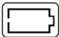
Replace Battery Icon: In the event that UPS batteries expire and require replacement, this icon and the warning icon will flash. This icon will also flash after a failed UPS self-test (see the BASIC OPERATION / CONTROL MENU OPTIONS / SELF-TEST section for more information).

Warning: This will flash to let the user know that there's a warning condition and immediate action must be taken:
- For Replace Battery: Replace Battery and Warning icons flash during any normal "Display" mode.
- For Overload: Load, Warning and Load Percentage icons will flash, the alarm will sound repeatedly and the LCD screen will switch from the user-selected display mode to Load Percentage. Overload indication is available in both AC and battery modes. CAUTION! Any overload condition that is not corrected by the user immediately may cause the UPS to shut down and cease supplying power in the event of a blackout or brownout.

EVENTS Icon: Displayed in conjunction with the AVR icon and BATT icons to indicate the number of On Battery or AVR events that have occurred.

Alarm Off: Indicates that the alarm is disabled.

Alarm On: Indicates that the alarm is enabled.
Basic Operation continued
INPUT
OUTPUT
LOAD
INPUT Icon: Indicates that the 3-digit value displayed is the Input Voltage.
OUTPUT Icon: Indicates that the 3-digit value displayed is the Output Voltage.
LOAD Icon: Displayed in two modes:
- Displayed in conjunction with the % icon and 3-digit value to indicate the load percentage.
- Displayed in conjunction with KWH/Day and 3-digit value to indicate daily power consumption.
- Both the LOAD icon and Warning icon will flash to indicate an overload.
BATT
BATT Icon: Displayed in two modes:
- BATT icon (displayed in conjunction with % icon and 3-digit value) indicates the Battery Capacity %.
- BATT icon is shown with TEST icon to indicate self-test mode or control mode.
%
TEST
% Icon: Indicates units of %.
RUNTIME
TEST Icon: Displayed in conjunction with BATT icon to indicate that the UPS is performing a self-test.
MIN
RUNTIME Icon: Displayed in conjunction with the MIN icon and 3-digit value to indicate Runtime in minutes.
VA
MIN Icon: Indicates units of minutes.
- Displayed in conjunction with RUNTIME icon and 3-digit value to indicate battery runtime in minutes.
- Displayed in conjunction with the 3-digit value (reporting "LCD") to indicate the minimum brightness.
K
VWA Icon: This is a multipurpose icon which indicates units of Volts, VA, Watts, or Amps (V, VA, W, or A will be shown).
/DAY
K Icon: Displayed in conjunction with the W to indicate Kilowatts. It is also used in conjunction with the WH and /DAY icons to indicate Kilowatt Hours per Day.
SENSITIVITY
H and /DAY Icons: Displayed in conjunction with "K" and "W" icons to indicate Kilowatt Hours per day (KWH/DAY).
SCROLL
Sensitivity Icon: Displayed to set the AC input line sensitivity setting. Sensitivity settings available are 100% (Normal = no delay), 50% (half delay), and 25% (full delay).
SCROLL Icon: When enabled, the display will automatically cycle through each DISPLAY mode of the LCD once per two-second interval. If a button is pressed while Scroll Mode is enabled, the scroll function will pause for 10 seconds to allow the user to manually make menu selections before resuming scroll.
Basic Operation continued
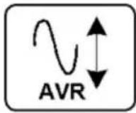
Automatic Voltage Regulation Icon: Indicates that the AC input is either low or high and that the AVR function is actively boosting or cutting the line. The AVR icon is also used in conjunction with the EVENTS icon to indicate AVR events.

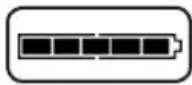
BATTERY CAPACITY Icon: Used to better describe the battery capacity bar graph.
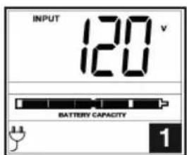
Display Power Conditions
Use the 📄 button to advance through power conditions.
text_image
INPUT 120 V BATTERY CAPACITY 1.3 1- Voltage In 2. Voltage Out 3. Estimated Runtime
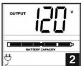
text_image
OUTPUT 120 V BATTERY CAPACITY 2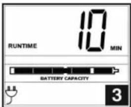
text_image
RUNTIME 10 MIN BATTERY CAPACITY 3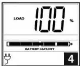
text_image
LOAD 100 % BATTERY CAPACITY 8.8 4(in minutes)
- Load %
text_image
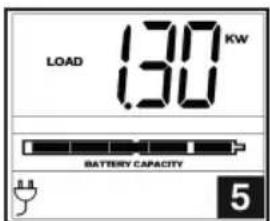
LOAD 1.30 KW BATTERY CAPACITY 5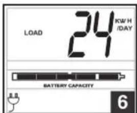
text_image
LOAD 24 KW/H /DAY BATTERY CAPACITY 6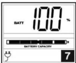
text_image
BATT 100 % BATTERY CAPACITY 7- Load Wattage* 6. KWH/Day** 7. Battery Capacity %
* Load Wattage is displayed in watts up to "999" and then will be displayed in Kilowatts.
** The Kilowatt Hour usage per day reports daily power consumption of equipment connected to the UPS in KWH in a 24-hour cycle. Press and hold the 🤗 button for 4 seconds to reset the accumulator to "0."
Note: When the UPS is in Battery Mode (power is supplied to the output from the batteries), the BATTERY icon will be lit in the display instead of the AC INPUT icon. The values displayed are random values used for example reference.
Basic Operation continued
Control Menu Options
Enable/Disable Alarm
Tap the button repeatedly to advance to the LCD display featuring the icon. Press the button to select ON or OFF alarm mode settings. The last option displayed before navigating away from this menu option will be the selected setting.
Note: Disabling the alarm via this control menu option will silence the alarm under all conditions, including low battery conditions.
LCD Brightness
Tap the M05 button repeatedly to advance to the LCD Brightness display marked "LCD." Press the button to select Medium Backlight (default), High Backlight or Dim Backlight. The last option displayed before navigating away from this menu option will be the selected setting.
Note: The default brightness is set at medium. Any time a button is pressed, the LCD will engage the high brightness setting. After 2 minutes of inactivity, the backlight will revert to the selected setting until a button is pressed.
Self-test
Tap the button repeatedly to advance to the TEST BATT display. Press the button to initiate the test. The test will last approximately 10 seconds as the UPS switches to battery to test the capacity with a load. Upon completion of the test, the display will indicate PAS or BAD (pass or bad) for 20 seconds, and then return to the home screen. Connected equipment can remain on during the test. Do not unplug your UPS to test it; this will remove safe electrical grounding.
Note: If the self-test result is BAD, it may be due to the batteries not being fully charged for 24 hours. Fully charge the batteries and repeat the self-test. Please refer to the note under Step 3 on page 6.
Scroll Control
This setting is normally set to “OFF.” Setting it to “ON” allows the user to select the option to automatically scroll each operating condition of the UPS (such as Input Voltage, Output Voltage and Runtime) automatically.

text_image
OFF SCROLL
text_image
ON SCROLLTap the Button repeatedly to advance to the Scroll display as shown above.
Press the button to advance to the next available option. The last option displayed, before navigating away from this menu option, will be the selected setting.
Note:
- Each condition is displayed in 2-second intervals.
- If a button is pressed while Scroll Mode is enabled, the scroll function will pause for 10 seconds to allow the user to manually make menu selections.
Basic Operation continued
ON Battery Events
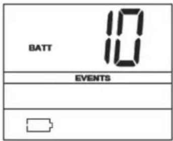
This feature allows the user to view the number of times the UPS has experienced an ON Battery Event. To reset the counter to "O," press and hold the 📋 button.
text_image
BATT 10 EVENTSTap the Button repeatedly to advance to the ON Battery Events display, as shown above.
Note: The value displayed is a random value used for example reference.
AVR Events
This feature allows the user to view the number of times the UPS has experienced an Automatic Voltage Regulation Event. To reset the counter to "0," press and hold the button.
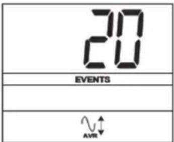
text_image
20 EVENTS AVRTap the button repeatedly to advance to the AVR display, as shown above.
Note: The value displayed is a random value used for example reference.
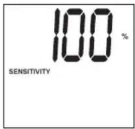
Power Sensitivity
This setting is normally set to 100%, which enables the UPS to protect against waveform distortions in its AC input. When such distortion occurs, the UPS will normally switch to providing pure sine wave power from its battery reserves for as long as the distortion is present. In some areas with poor utility power or where the UPS's input power comes from a backup generator, frequent brownouts and/or chronic waveform distortion could cause the UPS to switch to battery too often, draining its battery reserves. You may be able to reduce how often your UPS switches to battery due to waveform distortion or brownouts by experimenting with different settings. As the setting is reduced, the UPS becomes more tolerant of variations in its input power's AC waveform.
Note: When experimenting with different settings, operate connected equipment in a safe test mode so that the effect on the equipment of any waveform distortions in the UPS's output can be evaluated without disrupting critical operations. The test should last long enough so that all expected line conditions are encountered.
Basic Operation continued
Tap the button repeatedly to advance to Sensitivity display, as shown on the previous page.
text_image
100 % SENSITIVITY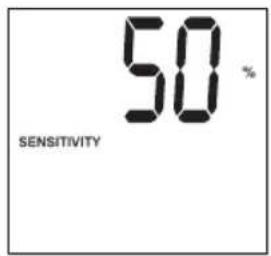
text_image
50 % SENSITIVITY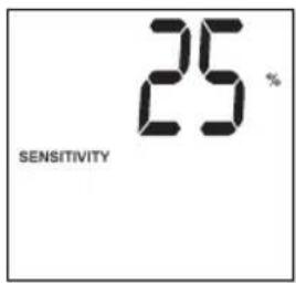
text_image
25% SENSITIVITYPress the button to advance through the options. The last option displayed before navigating away from this menu option will be the selected setting.
Factory Mode Reset
The LCD settings can be restored to Factory Mode by holding the MODE and ENTER/MUTE buttons simultaneously for 5 seconds while in any display mode.
CAUTION: This action cannot be undone.
Basic Operation continued
Other UPS Features (Rear Panel)
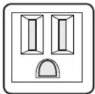
15A 120V
NEMA 5-15R
AC Outlets: All models include NEMA 5-15R outlets. These outlets provide your connected equipment with AC line power during normal operation and battery power during blackouts and brownouts. The UPS protects equipment connected to these outlets against damaging surges and line noise. If you have a serial or USB connection to your UPS, you can remotely reboot connected equipment by turning all of the outlets OFF and ON using Tripp Lite's PowerAlert Software.
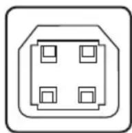
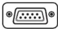
Communications Ports (USB or RS-232): These ports connect your UPS to any workstation or server. Use with Tripp Lite's PowerAlert Software and included cables to enable your computer to automatically save open files and shut down equipment during a blackout. Also use PowerAlert Software to monitor a wide variety of AC line power and UPS operating conditions. Consult your PowerAlert Software manual or contact Tripp Lite Customer Support for more information. See "USB and RS-232 Serial Communications" in the "Optional Installation" section for installation instructions.
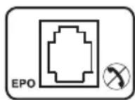
EPO (Emergency Power Off) Port: Your UPS features a EPO port that may be used to connect the UPS to a contact closure switch to enable emergency inverter shutdown. See Optional Installation.

Input Breaker: Your UPS features one breaker that protects your UPS. If one or more breakers trip, remove some of the load on the circuit(s), then reset them by pressing the breaker switch(es) in.
Ground Screw: Use this to connect any equipment that requires a chassis ground.
Storage and Service
Storage
Before storing your UPS, turn it completely OFF: with the UPS ON and receiving utility power, press and hold the "ON/OFF" button for two seconds (an alarm will beep once briefly after the interval has passed); then, unplug the UPS from the wall outlet. If you store your UPS for an extended period of time, recharge the UPS batteries once every three months: plug the UPS into a wall outlet; allow it to charge for 12 hours; and then unplug it and place it back in storage. If you leave your UPS batteries discharged for an extended period of time, they will suffer a permanent loss of capacity.
Service
A variety of Extended Warranty and On-Site Service Programs are available from Tripp Lite. For more information on service, visit www.tripplite.com/support. Before returning your product for service, follow these steps:
- Review the installation and operation procedures in this manual to insure that the service problem does not originate from a misreading of the instructions.
- If the problem continues, do not contact or return the product to the dealer. Instead, visit www.tripplite.com/support.
- If the problem requires service, visit www.tripplite.com/support and click the Product Returns link. From here you can request a Returned Material Authorization (RMA) number, which is required for service. This simple online form will ask for your unit's model and serial numbers, along with other general purchaser information. The RMA number, along with shipping instructions, will be e-mailed to you. Any damages (direct, indirect, special or consequential) to the product incurred during shipment to Tripp Lite or an authorized Tripp Lite service center is not covered under warranty. Products shipped to Tripp Lite or an authorized Tripp Lite service center must have transportation charges prepaid. Mark the RMA number on the outside of the package. If the product is within its warranty period, enclose a copy of your sales receipt. Return the product for service using an insured carrier to the address given to you when you request the RMA.
Battery Replacement
Under normal conditions, the original batteries in your UPS will last many years. See Safety section before replacing batteries. The batteries are designed for hot-swap replacement (i.e., leaving the UPS in ON mode), but some qualified service personnel may wish to put the UPS in the OFF mode and disconnect equipment before proceeding.
Note: Refer to the label on the battery retention plate for the R.B.C. part number.
SMC15002URM (RBC93-2U) and SMC10002URM (RBC24VLCD) Battery Replacement Procedure
1 Remove Front Panel
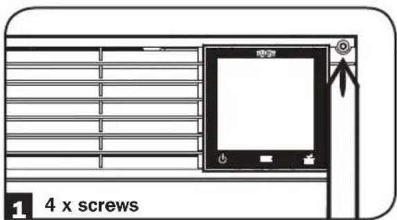
text_image
1 4 x screws3 Disconnect Batteries
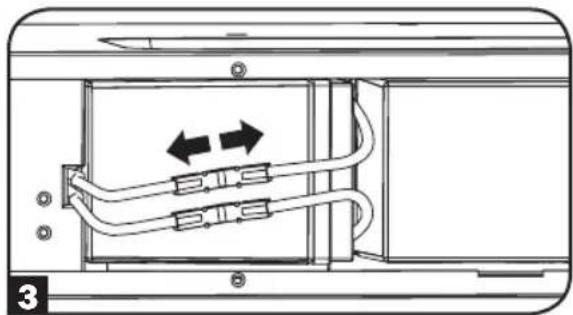
natural_image
Diagram of a device showing internal cable routing with two directional arrows (no text or symbols)2 Remove Battery Retention Plate
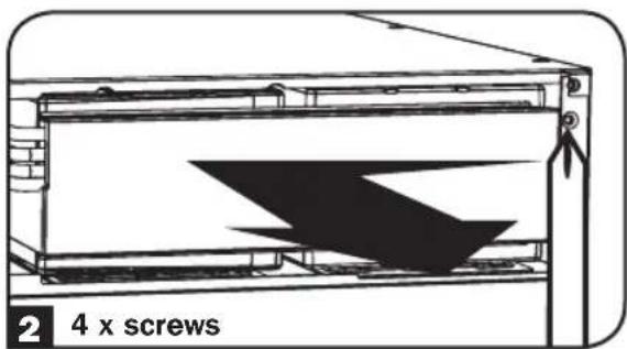
text_image
2 4 x screws4 Remove/Recycle Batteries
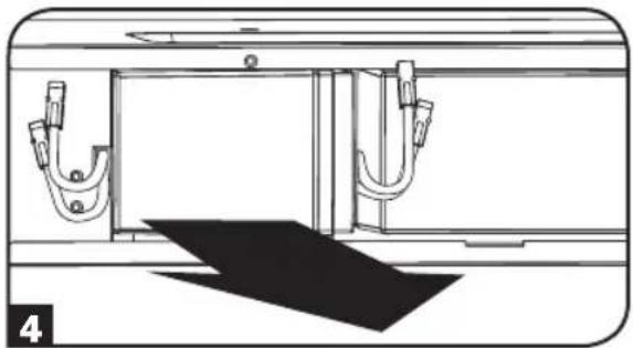
natural_image
Technical line drawing of a mechanical assembly with two U-shaped components and a shaded base (no text or symbols)Battery Replacement
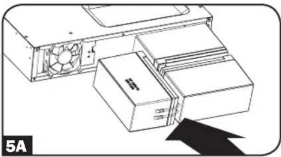
5A Add New Batteries (SMC15002URM)
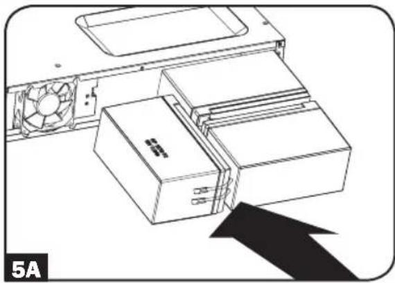
natural_image
Technical line drawing of a computer tower with fan and drive unit, no text or symbols present5B Add New Batteries (SMC10002URM)
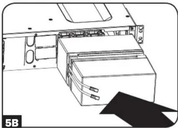
natural_image
Technical line drawing of an internal device with labeled components and a black arrow pointing to a component (no text or symbols present)6A Connect Batteries (SMC15002URM)
Attach both sets of connectors as shown: black-to-black and red-to-red.
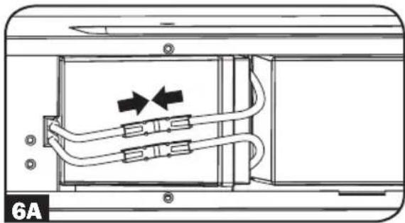
natural_image
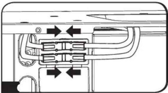
Diagram of a device showing internal cable routing with arrows indicating direction (no text or symbols)6B Connect Batteries (SMC10002URM)
Attach both sets of connectors as shown: black-to-black and red-to-red.
natural_image
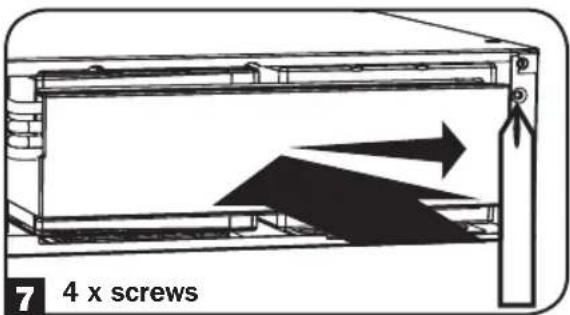
Pure mechanical diagram showing pipe connections without any text, numbers, or symbols7 Replace Battery Retention Plate
text_image
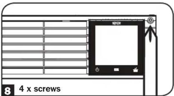
7 4 x screws8 Replace Front Panel
text_image
8 4 x screwsProduct Registration
Visit www.triplite.com/warranty today to register your new Tripp Lite product. You'll be automatically entered into a drawing for a chance to win a FREE Tripp Lite product!*
* No purchase necessary. Void where prohibited. Some restrictions apply. See Web site for details.
Regulatory Compliance
FCC Notice, Class A
This device complies with part 15 of the FCC Rules. Operation is subject to the following two conditions: (1) This device may not cause harmful interference; and (2) this device must accept any interference received, including interference that may cause undesired operation.
Note: This equipment has been tested and found to comply with the limits for a Class A digital device, pursuant to part 15 of the FCC Rules. These limits are designed to provide reasonable protection against harmful interference when the equipment is operated in a commercial environment. This equipment generates, uses, and can radiate radio frequency energy, and, if not installed and used in accordance with the instruction manual, may cause harmful interference to radio communications. Operation of this equipment in a residential area is likely to cause harmful interference in which case the user will be required to correct the interference at his own expense. The user must use shielded cables and connectors with this equipment. Any changes or modifications to this equipment not expressly approved by Tripp Lite could void the user's authority to operate this equipment.
Regulatory Compliance Identification Numbers
For the purpose of regulatory compliance certifications and identification, your Tripp Lite product has been assigned a unique series number. The series number can be found on the product nameplate label, along with all required approval markings and information. When requesting compliance information for this product, always refer to the series number. The series number should not be confused with the marking name or model number of the product.
Note on Labeling
Two symbols are used on the label.
V\~ : AC Voltage
V÷DC Voltage
Tripp Lite has a policy of continuous improvement. Product specifications are subject to change without notice.

text_image
TRIPP·LITE
Manufacturing Excellence.
1111 W. 35th Street, Chicago, IL 60609 USA • www.tripplite.com/support
natural_image
Line drawing of a rectangular electronic device with ventilation grilles and a digital display (no text or symbols)1111 W. 35th Street, Chicago, IL 60609 USA • www.tripplite.com/support
text_image
120° A.R.Instalación Rápida
natural_image
Line drawing of a hand inserting a plug into an electrical outlet (no text or symbols)natural_image
Line drawing of a hand inserting electrical plug into a panel (no text or symbols)3 Encienda el UPS.
text_image
USB TRIPP-LITE Model: SMC15002URM 1B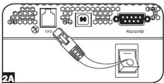
text_image
EPO RS232USB 2A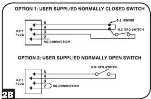
text_image
OPTION 1: USER SUPPLIED NORMALLY CLOSED SWITCH RJ11 PLUG 5 4 3 2 NO CONNECTION 4-5 JUMPER N.C. EPO SWITCH OPTION 2: USER SUPPLIED NORMALLY OPEN SWITCH RJ11 PLUG 5 4 3 2 NO CONNECTION N.O. EPO SWITCH 2BOperación Básica
Interfaz de LCD
text_image
TRIP-TITE INPUT OUTPUT LOAD TEST BATT RUNTIME 0.00 KVAH /DAY % Hz MIN SENSITIVITY EVENTS SCROLL EXTERNAL BATTERY CAPACITY X AVR ECO MODE RULEnatural_image
Diagram of a device showing internal cable routing with directional arrows (no text or symbols)natural_image
Technical line drawing of a mechanical assembly with two U-shaped components and a black diagonal shadow (no text or symbols)natural_image
Technical line drawing of a computer unit with fan and drive components, no text or symbols presentnatural_image
Technical line drawing of an electronic device with internal components and a black arrow pointing to a component (no text or symbols)natural_image
Diagram of a device showing internal cable routing with arrows indicating direction (no text or symbols)natural_image
Pure mechanical diagram showing internal components with directional arrows, no text or symbols present1111 W. 35th Street, Chicago, IL 60609 USA • www.tripplite.com/support
natural_image
Line drawing of a rectangular electronic device with ventilation grilles and a digital display (no text or symbols)Manufacturing Excellence.
1111 W. 35th Street, Chicago, IL 60609 USA • www.tripplite.com/support
natural_image
Line drawing of a hand inserting a plug into an electrical outlet (no text or symbols)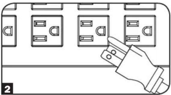
natural_image
Line drawing of a hand inserting a plug into multiple electrical socket blocks (no text or symbols)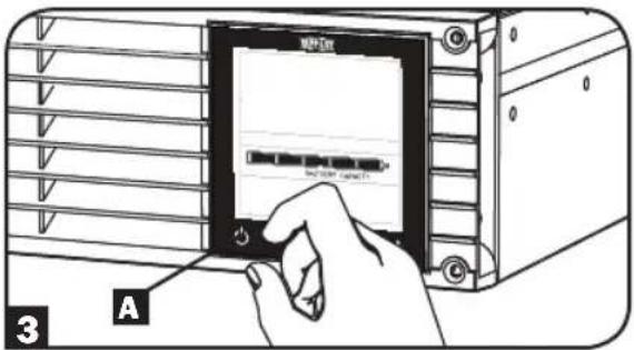
text_image
MPA-Tax 3 AInstallation en option
text_image
BATT 10 EVENTSnatural_image
Diagram of a device showing internal cable routing with two directional arrows (no text or symbols)natural_image
Technical line drawing of a mechanical assembly with two U-shaped components and a shaded base (no text or symbols)5A Installez les nouvelles batteries (SMC15002URM)
natural_image
Technical line drawing of a computer tower with fan and drive unit (no text or symbols)natural_image
Line drawing of an electronic device with a rack and cable, showing internal components and a black arrow pointing to a component (no text or symbols)natural_image
Diagram of a device showing internal cable routing with arrows indicating direction (no text or symbols)6B Branchez les batteries (SMC10002URM)
natural_image
Pure mechanical diagram showing internal components with directional arrows, no text or symbols presentTwo symbols are used on the label.
V\~ : AC Voltage
V÷DC Voltage

Manufacturing Excellence.
1111 W. 35th Street, Chicago, IL 60609 USA • www.tripplite.com/support