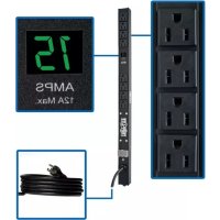
PDUMV1524 - Power strip Tripp Lite - Free user manual and instructions
Find the device manual for free PDUMV1524 Tripp Lite in PDF.


User questions about PDUMV1524 Tripp Lite
0 question about this device. Answer the ones you know or ask your own.
Ask a new question about this device
Download the instructions for your Power strip in PDF format for free! Find your manual PDUMV1524 - Tripp Lite and take your electronic device back in hand. On this page are published all the documents necessary for the use of your device. PDUMV1524 by Tripp Lite.
USER MANUAL PDUMV1524 Tripp Lite
PDUMV15-24, PDUMV15-36
(Series Number: AG-00E1)
PDUMV20-24, PDUMV20-36, PDUMV20-72
(Series Number: AG-00DD)
Important Safety Instructions 2
Installation 3
Features 4
Warranty & Product Registration 5
Español 6
Français 11
PROTECT YOUR INVESTMENT!
Register your product for quicker service and ultimate peace of mind.
You could also win an ISOBAR6ULTRA surge protector— a \$50 value!

text_image
QR code image containing encoded data, no visible human-readable textwww.tripplite.com/warranty

text_image
TRIPP·LITE
1111 W. 35th Street, Chicago, IL 60609 USA • www.tripplite.com/support
© 2014 Tripp Lite. All rights reserved.
Important Safety Instructions
SAVE THESE INSTRUCTIONS
This manual contains instructions and warnings that should be followed during the installation, operation and storage of this product. Failure to heed these instructions and warnings may affect the product warranty.

- The PDU provides the convenience of multiple outlets, but DOES NOT provide surge or line noise protection for connected equipment.
- The PDU is designed for indoor use only, in a controlled environment, away from excess moisture, temperature extremes, conductive contaminants, dust or direct sunlight.
- Keep indoor ambient temperature between 32^ and 122^ (0°C and 50°C).
- The PDU must be installed by a qualified technician only.
- Do not attempt to mount the PDU to an insecure or unstable surface.
• Install in accordance with National Electrical Code standards. Be sure to use the proper overcurrent protection for the installation, in accordance with the plug/equipment rating.
- Connect the PDU to an outlet that is in accordance with your local building codes and that is adequately protected against excess currents, short circuits and earth faults.
- The electrical outlets supplying power to the equipment should be installed near the equipment and easily accessible.
- Do not connect the PDU to an ungrounded outlet or to extension cords or adapters that eliminate the connection to ground.
- Be sure to provide a local disconnect device on any models that are permanently installed without a plug that is easily accessible.
- Never attempt to install electrical equipment during a thunderstorm.
- Individual equipment connected to the PDU should not draw more current than the individual PDU's outlet's rating.
- The total load connected to the PDU must not exceed the maximum load rating for the PDU.
- Do not attempt to modify the PDU, input plugs or power cables.
- Do not drill into or attempt to open any part of the PDU housing. There are no user-serviceable parts inside.
- Do not attempt to use the PDU if any part of it becomes damaged.
- Use of this equipment in life support applications where failure of this equipment can reasonably be expected to cause the failure of the life support equipment or to significantly affect its safety or effectiveness is not recommended. Do not use this equipment in the presence of a flammable anesthetic mixture with air, oxygen or nitrous oxide.
Installation
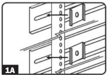
1A Zero U Rack Configuration. Attach the two mounting clips supplied with the PDU to the rack enclosure using the included hardware. The mounting clips should be attached along a vertical plane at equidistant points which roughly correspond to the center and ends of the PDU. The exact mounting configuration may vary depending on the rack and enclosure. If possible, use pre-existing mounting points within the enclosure.
13 Wall or Under-Counter Configuration. Attach the two mounting clips supplied with the PDU to a wall or similar flat, secure surface using the included hardware. The mounting clips should be attached along a vertical or horizontal plane at equidistant points which roughly correspond to the center and ends of the PDU. If possible, use pre-existing mounting points. WARNING: Do not attempt to mount the PDU with the outlets facing downward; the mounting clips are not designed to support the weight of the PDU in that manner.
1C Zero U Rack Configuration. For toolless mounting: Position the PDU as desired in the rack enclosure, align the buttons with the rack mounting slots and slide the PDU into position.
Note: Mounting buttons come preinstalled with select models.
Note: Regardless of configuration, the user must determine the fitness of hardware and procedures before mounting. The PDU and included hardware are designed for common rack and rack enclosure types and may not be appropriate for all applications.
2 Attach the PDU to the mounting clips. Using an assistant, place a rear corner of the PDU on the inside edge of the mounting clips, pivot the PDU toward the alternate inside edge and snap into place.
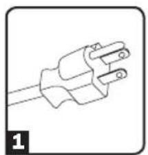
3 Attach the input plug of the PDU to a grounded outlet. Insert the plug directly into a grounded outlet that does not share a circuit with a heavy electrical load (such as an air conditioner or refrigerator).
4 Attach equipment to the PDU. Do not exceed the load rating of the PDU. The total electrical current used by the PDU will be displayed on the digital meter in amperes.
5 Optional Installation (Models PDUMV20-24, PDUMV20-36 and PDUMV20-72). The PDU includes an adapter that converts the L5-20P input plug to a 5-20P input plug. The adapter is optional; the PDU will work properly without connecting the adapter.
natural_image
Pure mechanical diagram showing two parallel plates with a central vertical gap and two hanging blocks, no text or symbols present.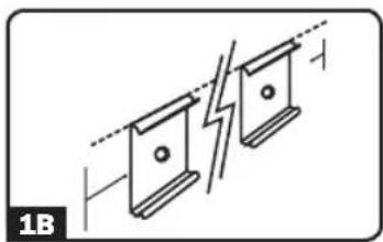
natural_image
Pure electrical circuit lines without any symbols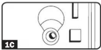
natural_image
Simple line drawing of a device with a circular lens and rectangular components (no text or symbols)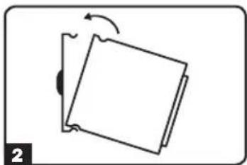
natural_image
Simple line drawing of a tilted rectangular object with an arrow indicating rotation (no text or symbols)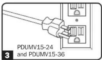
text_image
PDUMV15-24 and PDUMV15-36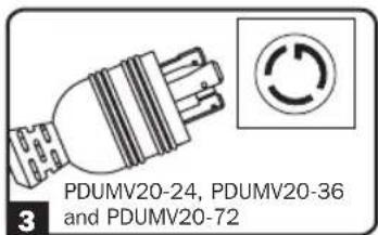
text_image
PDUMV20-24, PDUMV20-36 and PDUMV20-72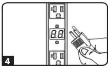
text_image
8.8 4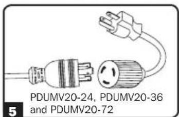
text_image
PDUMV20-24, PDUMV20-36 and PDUMV20-72Features
natural_image
Line drawing of a three-pin electrical plug (no text or symbols)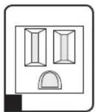
natural_image
Simple line drawing of two rectangular shapes with a semicircular base (no text or symbols)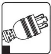
natural_image
Pure electrical plug diagram without any text, numbers, or symbols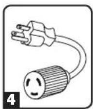
natural_image
Simple line drawing of an electrical plug with a circular fuse and power outlet (no text or symbols)
natural_image
Simple line drawing of three abstract geometric shapes with a curved base, no text or symbols present.
text_image
PRESS TO RESET 6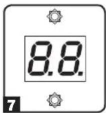
text_image
8.8.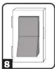
natural_image
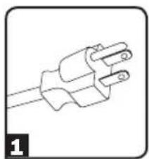
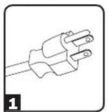
Simple 3D diagram of a rectangular box with a lid, no text or symbols present1 NEMA 5-15P Input Plug (Models PDUMV15-24 and PDUMV15-36)
2 NEMA 5-15R Outlets (Models PDUMV15-24 and PDUMV15-36)
3 NEMA L5-20P Input Plug (Models PDUMV20-24, PDUMV20-36 and PDUMV20-72)
4 NEMA 5-20P Plug Adapter (Models PDUMV20-24, PDUMV20-36 and PDUMV20-72): The adapter converts the input plug from NEMA L5-20P to NEMA 5-20P.
5 NEMA 5-15/20R Outlets (Models PDUMV20-24, PDUMV20-36 and PDUMV20-72)
6 Circuit Breaker: If the current drawn by the equipment connected to the PDU exceeds the Maximum Load Rating, the circuit breaker will trip to prevent possible damage. When the circuit breaker trips, its plunger will pop up. Disconnect excess equipment and allow the breaker to cool at least one minute before depressing the plunger to reset the breaker.
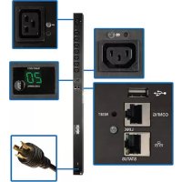
7 Ammeter: The total electrical current used by the PDU will be displayed on the digital meter in amperes.
8 Illuminated Power Switch with Cover: The switch will illuminate red when power is applied to the PDU. The plastic cover protects against accidentally turning the system on or off.
Warranty & Product Registration
LIMITED WARRANTY
Seller warrants this product, if used in accordance with all applicable instructions, to be free from original defects in material and workmanship for a period of 2 years (except internal UPS system batteries outside USA and Canada, 1 year) from the date of initial purchase. If the product should prove defective in material or workmanship within that period, Seller will repair or replace the product, in its sole discretion. Service under this Warranty can only be obtained by your delivering or shipping the product (with all shipping or delivery charges prepaid) to: Tripp Lite, 1111 W. 35th Street, Chicago, IL 60609 USA. Seller will pay return shipping charges. Visit www.tripplite.com/support before sending any equipment back for repair.
THIS WARRANTY DOES NOT APPLY TO NORMAL WEAR OR TO DAMAGE RESULTING FROM ACCIDENT, MISUSE, ABUSE OR NEGLECT. SELLER MAKES NO EXPRESS WARRANTIES OTHER THAN THE WARRANTY EXPRESSLY SET FORTH HEREIN. EXCEPT TO THE EXTENT PROHIBITED BY APPLICABLE LAW, ALL IMPLIED WARRANTIES, INCLUDING ALL WARRANTIES OF MERCHANTABILITY OR FITNESS, ARE LIMITED IN DURATION TO THE WARRANTY PERIOD SET FORTH ABOVE; THIS WARRANTY EXPRESSLY EXCLUDES ALL INCIDENTAL AND CONSEQUENTIAL DAMAGES. (Some states do not allow limitations on how long an implied warranty lasts, and some states do not allow the exclusion or limitation of incidental or consequential damages, so the above limitations or exclusions may not apply to you. This Warranty gives you specific legal rights, and you may have other rights which vary from jurisdiction to jurisdiction).
WARNING: The individual user should take care to determine prior to use whether this device is suitable, adequate or safe for the use intended. Since individual applications are subject to great variation, the manufacturer makes no representation or warranty as to the suitability or fitness of these devices for any specific application.
PRODUCT REGISTRATION
Visit www.triplite.com/warranty today to register your new Tripp Lite product. You'll be automatically entered into a drawing for a chance to win a FREE Tripp Lite product!*
* No purchase necessary. Void where prohibited. Some restrictions apply. See website for details.
Regulatory Compliance Identification Numbers
For the purpose of regulatory compliance certifications and identification, your Tripp Lite product has been assigned a unique series number. The series number can be found on the product nameplate label, along with all required approval markings and information. When requesting compliance information for this product, always refer to the series number. The series number should not be confused with the marking name or model number of the product.
The policy of Tripp Lite is one of continuous improvement. Specifications are subject to change without notice.

text_image
TRIPP·LITE
1111 W. 35th Street, Chicago, IL 60609 USA • www.tripplite.com/support
PDUMV15-24, PDUMV15-36
(Número de Serie: AG-00E1)
PDUMV20-24, PDUMV20-36, PDUMV20-72
(Número de Serie: AG-00DD)
1111 W. 35th Street, Chicago, IL 60609 USA • www.tripplite.com/support
natural_image
Pure mechanical diagram showing two vertical components with arrows indicating direction, no text or symbols present
natural_image
Pure electrical circuit lines without any symbols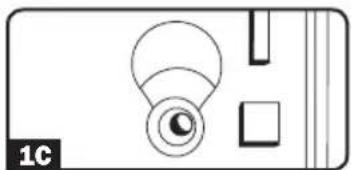
natural_image
Simple line drawing of a camera lens and square frame (no text or symbols)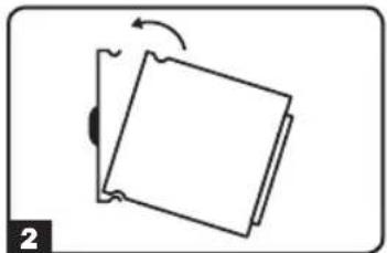
natural_image
Simple line drawing of a tilted rectangular object with an arrow indicating rotation, no text or symbols present.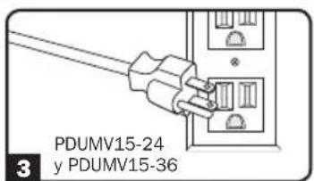
text_image
PDUMV15-24 y PDUMV15-36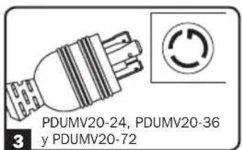
text_image
PDUMV20-24, PDUMV20-36 y PDUMV20-72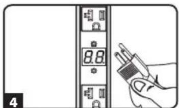
text_image
8.8 4
text_image
PDUMV20-24, PDUMV20-36 y PDUMV20-72Características
natural_image
Line drawing of a plug with two leads (no text or symbols)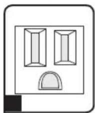
natural_image
Simple line drawing of two rectangular blocks above a semicircular shape, no text or symbols present.
natural_image
Pure electrical plug diagram without any text, numbers, or symbols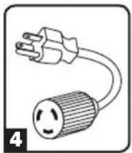
natural_image
Simple line drawing of an electrical plug with a circular connector (no text or symbols)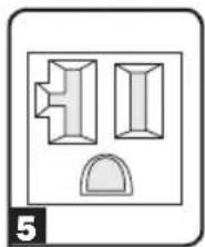
natural_image
Simple line drawing of a mechanical component with two views and a dome (no text or symbols)
text_image
PRESS TO RESET 6
text_image
8.8. 7
natural_image
Simple 3D diagram of a rectangular box with a side panel, no text or symbols present1111 W. 35th Street, Chicago, IL 60609 USA • www.tripplite.com/support
PDUMV15-24, PDUMV15-36
(Número de Série : AG-00E1)
PDUMV20-24, PDUMV20-36, PDUMV20-72
(Número de Série : AG-00DD)
Manufacturing Excellence.
1111 W. 35th Street, Chicago, IL 60609 USA • www.tripplite.com/support
natural_image
Pure mechanical diagram showing two blocks with arrows indicating direction, no text or symbols present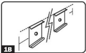
natural_image
Pure electrical circuit lines without any symbols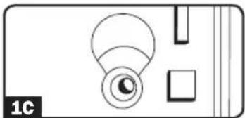
natural_image
Simple line drawing of a device with a circular component and rectangular elements (no text or symbols)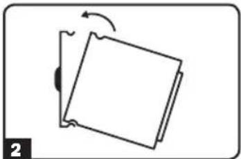
natural_image
Simple line drawing of a tilted rectangular object with an arrow indicating rotation (no text or symbols)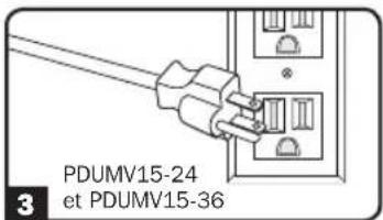
text_image
PDUMV15-24 et PDUMV15-36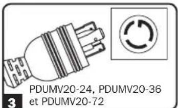
text_image
PDUMV20-24, PDUMV20-36 et PDUMV20-72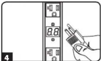
text_image
8.8 4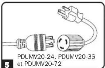
text_image
PDUMV20-24, PDUMV20-36 et PDUMV20-72Caractéristiques
natural_image
Simple line drawing of a three-pin electrical plug (no text or symbols)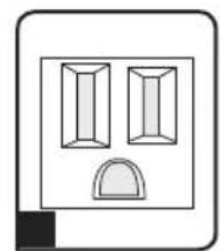
natural_image
Simple line drawing of two rectangular shapes above a curved semicircle (no text or symbols)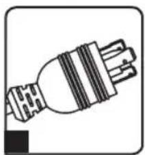
natural_image
Simple line drawing of a plug with three leads (no text or symbols)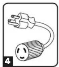
natural_image
Simple line drawing of an electrical plug with a circular fuse (no text or symbols)
natural_image
Simple line drawing of two abstract geometric shapes with a curved base, no text or symbols present.
text_image
PRESS TO RESET 6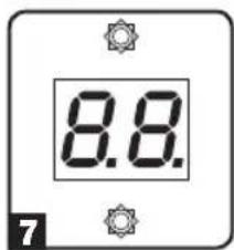
text_image
8.8. 7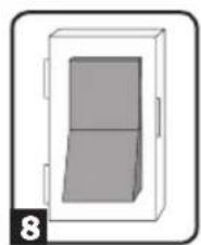
natural_image
Simple line drawing of a door with a side panel, no text or symbols present1111 W. 35th Street, Chicago, IL 60609 USA • www.tripplite.com/support