
CST20AC - Phone charger Tripp Lite - Free user manual and instructions
Find the device manual for free CST20AC Tripp Lite in PDF.

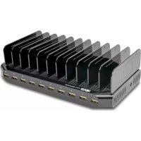
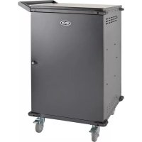
| Product Type | Mobile Device Charging Station Tower (charger & storage) |
| Model | CST20AC |
| Brand | Tripp Lite |
| Charging Capacity | 20 devices simultaneously |
| Dimensions (H × W × D) | 1334 × 330 × 533 mm (52.5 × 13 × 21 in) |
| Weight (approx.) | 45 kg (estimated) |
| Input Power | 120 V AC, 50/60 Hz, 15 A |
| Maximum Power | 1440 W |
| AC Outlets | 20 NEMA 5-15R outlets |
| Electrical Protection | 15 A input circuit breaker |
| Lockable Door | Yes, with keys provided |
| Operating Temperature | 0 to 40 °C |
| Operating Humidity | 5 to 95% RH (non-condensing) |
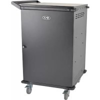
| Housing Material | Heavy-duty steel |
| Device Compatibility | Chromebooks and tablets up to 38.1 cm (15 inches) |
| Wall Mounting | Wall brackets with keyhole slots (hardware not included) |
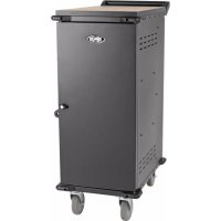
| Mobility Options | Optional caster kit (model CSTCASTERKIT20) |
| Warranty | 2 years |
| Maintenance | Clean with a damp, lint-free cloth; avoid solvents and aerosols |
| Safety | Do not use outdoors, avoid moisture and heat sources |
Frequently Asked Questions - CST20AC Tripp Lite
User questions about CST20AC Tripp Lite
0 question about this device. Answer the ones you know or ask your own.
Ask a new question about this device
Download the instructions for your Phone charger in PDF format for free! Find your manual CST20AC - Tripp Lite and take your electronic device back in hand. On this page are published all the documents necessary for the use of your device. CST20AC by Tripp Lite.
USER MANUAL CST20AC Tripp Lite
Charging Station Towers
Models: CST16AC (16 Slots), CST20AC (20 Slots)
- Important Safety Instructions 2
- Overview 3
- Feature Identification 3
- Setup 4
4.1 Unpacking 4
4.2 Preparation 4
4.3 Connecting Power Adapters 6
- Installation 7
5.1 Power Requirements 7
5.2 Mounting the Charging Station Tower 7
5.3 Powering the Charging Station Tower 8
5.4 Connecting Devices 8
5.5 Door Locks 9
- Specifications 9
- Optional Caster Kit 10
- Storage, Service and Cleaning 10
- Warranty and Product Registration 11
Español 12
Français 23
WARRANTY REGISTRATION
Register your product today and be automatically entered to win an ISOBAR surge protector in our monthly drawing!
tripplite.com/warranty


Manufacturing Excellence.
1. Important Safety Instructions
SAVE THESE INSTRUCTIONS
This manual contains instructions and warnings that must be followed during the installation and operation of the product described in this manual. Failure to comply may invalidate the warranty and cause property damage or personal injury.
AC Power Distribution Unit:
- To remove the AC power distribution unit from the supply mains, the power cord serves as a disconnect device.
- If any of the following situations arise, have your equipment inspected by a service technician:
- The equipment has been exposed to moisture.
- The equipment has been dropped and damaged.
• The equipment shows obvious signs of breakage.
- The equipment is not functioning properly or is not functioning according to the instructions described in this Owner's Manual.
- Use of this equipment in life support applications where failure of this equipment can reasonably be expected to cause the failure of the life support equipment or to significantly affect its safety or effectiveness is not recommended.
Charging Station Tower Unit:
- Keep the charging station tower unit in a controlled indoor environment away from moisture, temperature extremes, flammable liquids and gasses, conductive contaminants, dust and direct sunlight.
- Leave adequate space at the front and top of the charging station tower unit for proper ventilation.
- The charging station tower unit is heavy. Use caution when handling the enclosure. Do not attempt to unpack, move or install it unassisted.
- Do not place any object on the charging station tower unit, especially containers of liquid, and do not attempt to stack charging station tower units.
- Inspect the shipping container and the charging station tower unit for shipping damage. Do not use the charging station tower unit if it is damaged.
- Make sure the charging station tower unit is placed in a structurally sound area capable of bearing the weight of the charging station tower unit, all equipment that will be installed, and any other charging station tower units and/or equipment that will be installed nearby.
- Charging station tower unit must be installed by a qualified technician.
- Use suitable mounting means when installing to cinder block, concrete, drywall or wood studs.
- Use caution when cutting packing materials. The charging station tower unit could be scratched, causing damage not covered by the warranty.
- Save all packing materials for later use. Repacking and shipping the charging station tower unit without the original packing materials may cause product damage that will void the warranty.
If installing optional CSTCASTERKITXX caster kit
(refer to section 6. Optional Caster Kit):
- When rolling the charging station tower on its casters, always push it from behind using the handles. Never pull the unit.
- A rolling charging station tower can cause personal injury and property damage if not properly supervised. If rolling the enclosure down a ramp is required, use extreme caution. Do not attempt to use ramps that have a slope grade greater than 12% .
2. Overview
Tripp Lite's CST Charging Station Towers are a space-saving solution for charging and securely storing 16 or 20 mobile devices. Designed for Chromebooks and tablets with screens up to 15 inches, the towers have a small footprint to fit in tight or crowded spaces. An open frame allows you to see devices without unlocking and opening the half door.
3. Feature Identification
Front View Rear View
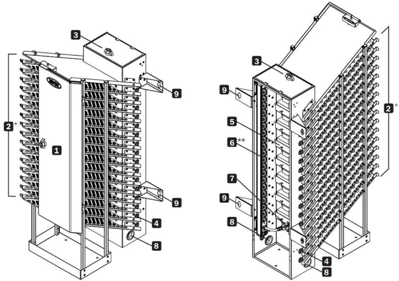
*CST16AC 16-device slot model shown. CST20AC contains 20 device slots.
**Both the CST16AC and CST20AC models use a 20-outlet power distribution unit.
1 Locking Front Door
2 Storage Shelves
3 Locking Access Door
4 Power Connector Bushing
5 Power Adapter Shelves
6 AC Power Distribution Unit
7 10 ft. Power Cord with 5-15P Plug
8 Power Cord Access Hole
9 Wall-Mount Brackets with Keyhole Slots
Not Shown: Keys
4. Setup

Caution! Read all instructions and warnings before installation!

Warning: The charging station tower unit is heavy. Use caution when handling the charging station tower unit. Do not attempt to unpack, move or install it unassisted. Use extreme caution when handling the charging station tower unit. Always make sure to follow all handling and installation instructions.
4.1 Unpacking

Use at least two people to unpack the unit.
Note: The charging station tower should be moved close to its installation location inside its shipping container before it is unpacked. For mobile applications, use the CSTCASTERKIT16 or CSTCASTERKIT20 caster, handle and door accessory kit.
Upon unpacking, examine for any additional packing material. Make sure to remove all packing materials from the interior and exterior of the unit. Save all packing materials for later use, unless you are certain they will not be required. Packing materials are recyclable.
2 With one person on each side, carefully move the charging station tower unit to a firm, level surface.
3 Examine the charging station tower unit and its contents for any damage or loose parts. Confirm all parts are present. If anything is missing or damaged, contact Tripp Lite for assistance. Do not attempt to use the charging station tower if it has been damaged.
4.2 Preparation
The charging station tower unit must be installed in a structurally sound area capable of bearing the weight of the charging station tower unit, all equipment that will be installed, and any other charging station tower units and/or equipment that will be installed nearby. Before unpacking, first transport the shipping container close to the final installation location to minimize the distance you will need to move the charging station tower unit after the protective packaging has been removed. If you plan to store the charging station tower unit for an extended period before installation, follow the instructions in section 7. Storage, Service and Cleaning.
Note: The charging station tower must be installed by a qualified technician.
To secure the charging station tower to a wall, you will need:
- Level
- Pencil or other marking device
- Appropriate tools for wall mounting
- Appropriate hardware for wall mounting (not included)
4. Setup
1 Determine the charging station tower's permanent mounting location along the wall. Ensure the 10-ft. power cord and input plug are able to connect to a nearby power outlet.
2 Use the included fold-out template to mark the locations where the charging station tower's wall-mount brackets will be used to secure the charging station tower to the wall A.
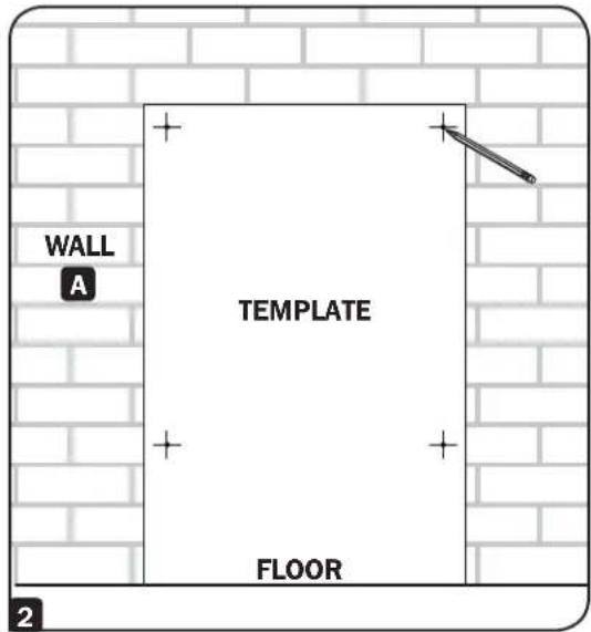
3 Install appropriate fasteners (not included) on the wall according to the locations marked from the template in step 2. Use suitable mounting means when installing to cinder block, concrete, drywall or wood studs. Make sure to leave approximately 5 mm space between the hardware and the wall.
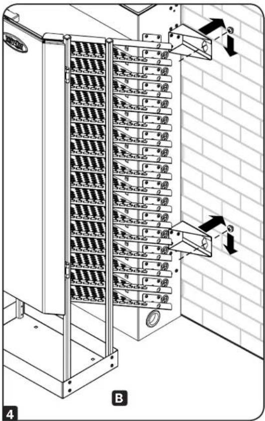
4 With the help of an assistant, lift the charging station tower and align its keyhole slots with the mounting hardware. Then, push in the charging station tower so it is flush against the wall and carefully lower the charging station tower to the ground B.

The supporting surfaces must be able to safely support the combined load of the equipment and all attached hardware and components. The charging station tower is not designed to hang from a wall and should always be placed firmly on a ground surface. For more information on your model's weight and dimensions, refer to 5. Specifications in this manual.
5 If no further adjustments are needed, again with the help of an assistant, lift the charging station and remove the unit from the wall-mount hardware. Proceed to section 4.3 Connecting Power Adapters.
4. Setup
4.3 Connecting Power Adapters

When installing power adapters, always start from the bottom of the charging station tower. Any unused device slots closer to the top of the unit will allow for easier future expansion of installed devices.
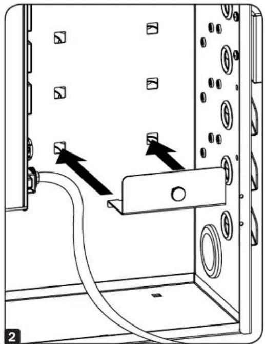
Installing Power Adapter Shelves
1 The included power adapter shelves provide secure mounting for the devices' AC power supplies. Starting at the bottom of unit in the order as shown,
2 Insert the power adapter shelf tabs into the slots located on the tower's rear panel. Repeat as needed.
*CST16AC 16-device slot model shown. CST20AC contains 20 power adapter shelves and slots.

natural_image
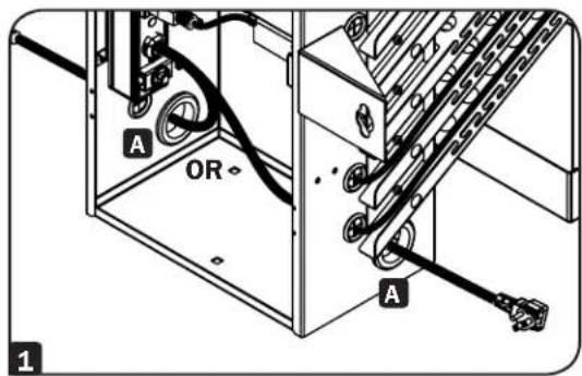
Diagram of a device interior showing cable routing and mounting points (no text or symbols)Installing the Device's AC Power Supply
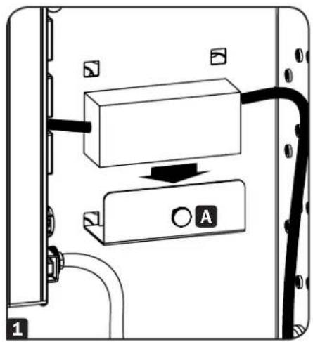
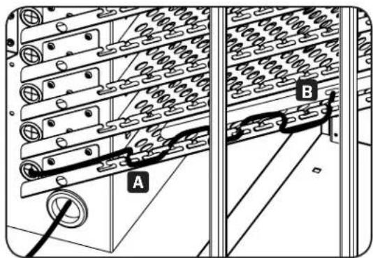
1 Place the device's AC power supply on the power adapter shelf and secure with the thumbscrew A.
2 Then, plug the device's AC power supply into the power distribution unit B (starting with the lowermost outlet).
3 Run the AC power connector through the corresponding power connector bushing C located on the side of the charging station tower unit. Repeat for each additional device.
natural_image
Diagram of a device panel with labeled components and wiring (no readable text or symbols)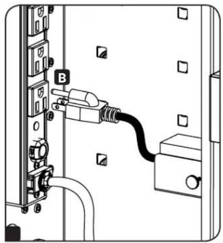
natural_image
Diagram of an electrical outlet with a plug inserted into a socket, showing wiring and mounting components (no text or labels)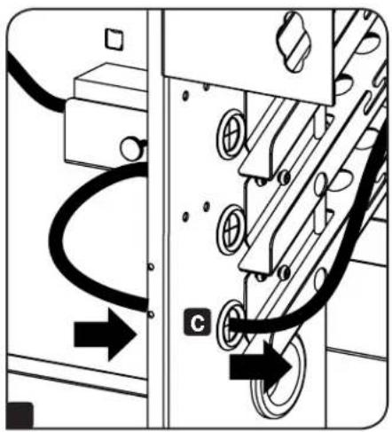
natural_image
Pure electrical circuit lines without any symbols5. Installation
5.1 Power Requirements
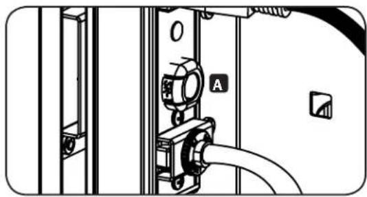
The charging station must be plugged into an AC outlet with a dedicated circuit. An AC outlet with a 20-amp (NEMA 5-20R) AC circuit is recommended for powering the charging station. The AC outlet used to power the charging station should not be shared. The total wattage of the charging station and all connected components should not exceed 1440 watts. The AC power distribution unit is protected by a 15-amp input breaker A.
natural_image
Technical diagram of a mechanical or electrical component with labeled parts (no readable text or symbols)5.2 Mounting the Charging Station Tower

Warning: Do not attempt to mount the charging station tower to the wall with any electronic devices inside the charging tower's device trays.
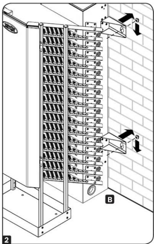
1 Pull the input cord through one of the two cable access hole grommets located at the bottom of the charging station tower A.
2 With the help of an assistant, lift the charging station tower and align its keyhole slots with the mounting hardware (installed in step 3 of the 4.2 Preparation section). Then, push in the charging station tower so it is flush against the wall and carefully lower the charging station tower to the ground B.
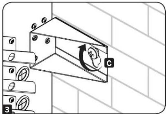
5. Installation
3 To secure the charging station tower to the wall, tighten the mounting hardware to the charging station tower's wall-mount brackets C.
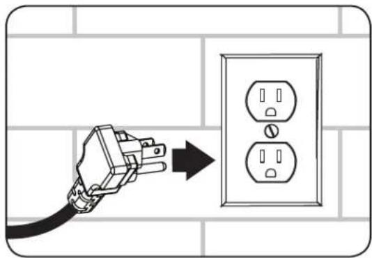
5.3 Powering the Charging Station Tower
Once all AC power supplies have been connected to the charging tower's distribution unit (see section 4.3 Connecting Power Adapters) and the charging station has been secured to a wall surface (see section 5.2 Mounting the Charging Station Tower), connect the charging station tower's input plug to the nearest 3-prong, grounded wall outlet.
natural_image
Illustration of a hand holding an electrical outlet with a power plug, showing three socket outlets (no text or symbols present)5.4 Connecting Devices
Once all AC power supplies are connected to the charging tower's power distribution unit and all power connectors have passed through its corresponding power connector bushing (see section 4.3 Connecting Power Adapters), use the cable management slots on the charging station tower's storage shelves to route and organize the device's power cable A. Connect a device to charge B, push any excess cable back through the power connector bushing and repeat for each additional device.
5. Installation
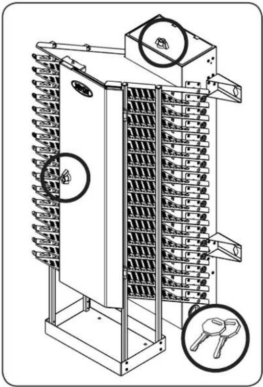
5.5 Door Locks
The doors contain a set of locks that are accessible with the included keys. The top door allows for easy access to any unused device slots near the top of the unit for easier future expansion of installed devices.
natural_image
Technical line drawing of a multi-tiered industrial control unit with visible gears and key symbols (no text or labels)6. Specifications
| Model CST16AC CST20AC | |
| Dimensions (H x W x D) 44.5 x 13 x 21 in. / 1130 x 330 x 533 mm 52.5 x | 13 x 21 / 1334 330 x 533 mm |
| AC Receptacles Power Distribution Unit: 20 x 5-15R | |
| Power Requirement Input: 120V AC, 50/60 Hz, 15 Amps | |
| Operating Temperature 32° to 104° F / 0° to 40° C | |
| Operating Humidity 5 to 95% RH, Non-Condensing | |
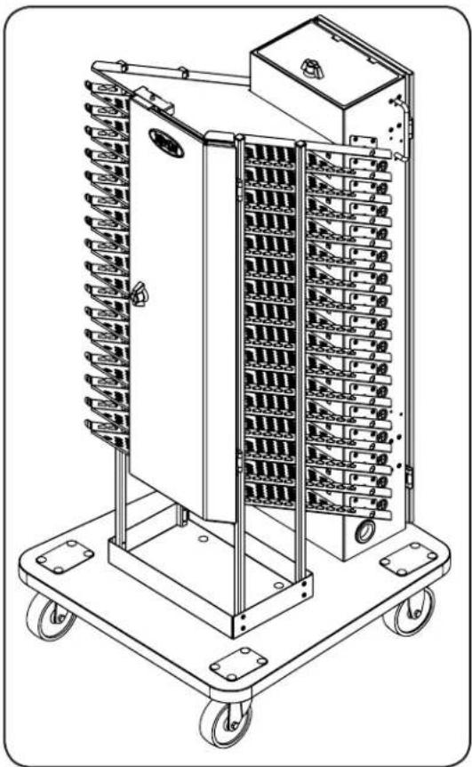
7. Optional Caster Kit
For applications requiring extra mobility, an optional caster kit (Model: CSTCASTERKIT16 or CSTCASTERKIT20) contains four casters, a base, handle set and locking rear door. For further installation instructions, refer to the manual included with the caster kit.
natural_image
Technical line drawing of a multi-tiered industrial machine with wheels and internal compartments (no text or symbols)8. Storage, Service and Cleaning
Storage
The enclosure should be stored in a controlled indoor environment away from moisture, temperature extremes, flammable liquids and gasses, conductive contaminants, dust and direct sunlight. Store the enclosure in its original shipping container if possible.
Service
The enclosure is covered by the limited warranty described in this manual. For more information, visit www.tripplite.com/support.
Cleaning
Before cleaning, always power off the charging station by unplugging it from its AC source. Dampen a clean, lint-free cloth with water and wipe down the unit, as necessary. Allow the surface area to dry before plugging in the unit.
Note: Avoid using abrasive cloths, solvents or aerosol sprays to clean the charging station; doing so can damage the unit.
9. Warranty and Product Registration
Seller warrants this product, if used in accordance with all applicable instructions, to be free from original defects in material and workmanship for a period of 2 years from the date of initial purchase. If the product should prove defective in material or workmanship within that period, Seller will repair or replace the product, at its sole discretion.
THIS WARRANTY DOES NOT APPLY TO NORMAL WEAR OR TO DAMAGE RESULTING FROM ACCIDENT, MISUSE, ABUSE OR NEGLECT. SELLER MAKES NO EXPRESS WARRANTIES OTHER THAN THE WARRANTY EXPRESSLY SET FORTH HEREIN. EXCEPT TO THE EXTENT PROHIBITED BY APPLICABLE LAW, ALL IMPLIED WARRANTIES, INCLUDING ALL WARRANTIES OF MERCHANTABILITY OR FITNESS, ARE LIMITED IN DURATION TO THE WARRANTY PERIOD SET FORTH ABOVE; AND THIS WARRANTY EXPRESSLY EXCLUDES ALL INCIDENTAL AND CONSEQUENTIAL DAMAGES. (Some states do not allow limitations on how long an implied warranty lasts, and some states do not allow the exclusion or limitation of incidental or consequential damages, so the above limitations or exclusions may not apply to you. This warranty gives you specific legal rights, and you may have other rights which vary from jurisdiction to jurisdiction).
WARNING: The individual user should take care to determine prior to use whether this device is suitable, adequate or safe for the use intended. Since individual applications are subject to great variation, the manufacturer makes no representation or warranty as to the suitability or fitness of these devices for any specific application.
Product Registration
Visit tripplite.com/warranty today to register your new Tripp Lite product. You'll be automatically entered into a drawing for a chance to win a FREE Tripp Lite product!*
* No purchase necessary. Void where prohibited. Some restrictions apply. See website for details.
Regulatory Compliance Identification Numbers
For the purpose of regulatory compliance certifications and identification, your Tripp Lite product has been assigned a unique series number. The series number can be found on the product nameplate label, along with all required approval markings and information. When requesting compliance information for this product, always refer to the series number. The series number should not be confused with the marketing name or model number of the product.
Tripp Lite has a policy of continuous improvement. Specifications are subject to change without notice. Photos and illustrations may differ slightly from actual products.


1111 W. 35th Street, Chicago, IL 60609 USA • tripplite.com/support
1111 W. 35th Street, Chicago, IL 60609 EE UU • tripplite.com/support
4. Ensamble
natural_image
Diagram of a device interior showing cable routing and mounting points (no text or symbols)natural_image
Diagram of an electrical panel with two blocks, a switch, and a labeled component (no text or symbols present)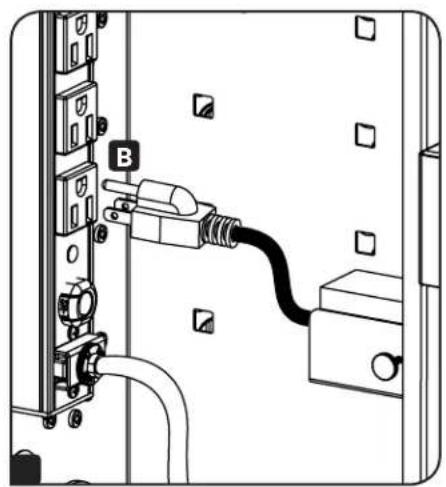
natural_image
Diagram of an electrical outlet with a black cable inserted into a socket, showing no text or symbols.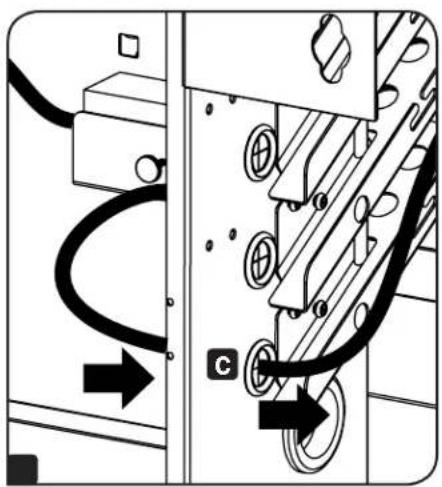
natural_image
Pure electrical circuit lines without any symbols5. Instalación
natural_image
Technical diagram of a mechanical or electrical component with labeled parts (no readable text or symbols)5. Instalación
natural_image
Illustration of a hand holding an electrical outlet with three socket switches, connected to a wall-mounted power strip (no text or symbols)5. Instalación
natural_image
Technical line drawing of a multi-tiered industrial control unit with visible gears and key symbols (no text or labels)6. Especificaciones
natural_image
Technical line drawing of a multi-tiered industrial machine with wheels and internal compartments (no text or symbols)1111 W. 35th Street, Chicago, IL 60609 USA • tripplite.com/support
4. Configuration
natural_image
Diagram of a server rack with cable and socket, showing two arrows pointing to components (no text or symbols present)natural_image
Diagram of a device panel with labeled components, showing connections and a directional arrow (no text or symbols present)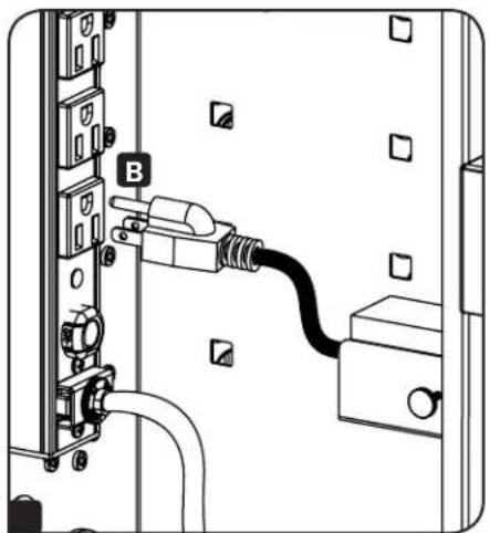
natural_image
Line drawing of an electrical outlet with a plug inserted into a socket (no text or symbols)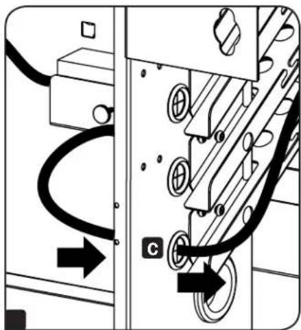
natural_image
Pure electrical circuit lines without any symbols5. Installation
natural_image
Technical diagram of a mechanical or electrical component with labeled parts (no readable text or symbols)5. Installation
natural_image
Illustration of a hand inserting a plug into an electrical outlet (no text or symbols)5. Installation
natural_image
Technical line drawing of a multi-tiered industrial control unit with visible gears and key components (no text or labels)natural_image
Technical line drawing of a multi-tiered industrial control unit with wheels and internal compartments (no text or symbols)1111 W. 35th Street, Chicago, IL 60609 USA • tripplite.com/support
- Charging Station Towers
- WARRANTY REGISTRATION
- Important Safety Instructions
- SAVE THESE INSTRUCTIONS
- AC Power Distribution Unit:
- Charging Station Tower Unit:
- If installing optional CSTCASTERKITXX caster kit
- (refer to section 6. Optional Caster Kit):
- Overview
- Feature Identification
- Setup
- Caution! Read all instructions and warnings before installation!
- Unpacking
- Use at least two people to unpack the unit.
- Preparation
- Connecting Power Adapters
- Installing Power Adapter Shelves
- Installing the Device's AC Power Supply
- Installation
- Power Requirements
- Mounting the Charging Station Tower
- Powering the Charging Station Tower
- Connecting Devices
- Door Locks
- Specifications
- Optional Caster Kit
- Storage, Service and Cleaning
- Storage
- Service
- Cleaning
- Warranty and Product Registration
- Product Registration
- Regulatory Compliance Identification Numbers
- Ensamble
- Instalación
- Especificaciones
- Configuration
Brand : Tripp Lite
Model : CST20AC
Category : Phone charger