YTHM5421R1010 - Controller HONEYWELL - Free user manual and instructions
Find the device manual for free YTHM5421R1010 HONEYWELL in PDF.

| Product Type | Thermostat controller with RedLINK equipment interface module |
| Brand | Honeywell |
| Model | YTHM5421R1010 |
| Application | Residential and light commercial |
| Compatible system types | Conventional (up to 3 heat stages/2 cool stages) and heat pump (up to 4 heat stages/2 cool stages) |
| Wireless technology | RedLINK (wireless communication between thermostat and module) |
| Module power supply | 18 to 30 VAC, 50/60 Hz via transformer (24 V typical) |
| Operating temperature (module) | -40 to 74 °C |
| Operating humidity (module) | 5% to 95% non-condensing |
| Dimensions (module) | 91 x 147 x 42 mm (height x width x depth) |
| Weight (module) | Not specified in documentation (estimated ~200 g) |
| Enclosure material | Plastic (not explicitly specified) |
| Number of zones | Up to multiple zones (managed via gateway and accessories) |
| Compatible accessories | Prestige IAQ / VisionPRO 8000 thermostat, RedLINK Internet gateway, wireless indoor/outdoor sensors, portable controller, wireless adapter |
| Wiring terminals | R, C, W, Y, G, W2, Y2, W3, A/L, U1, U2, U3, S1-S4, ABCD |
| Main functions | Heating/cooling control, humidification, dehumidification, ventilation, economizer, dry contact alerts, Delta T diagnostic |
| Installation | Wall mounting near HVAC equipment, requires qualified technician |
| Maintenance | No special maintenance; check connections and batteries if used |
| Safety | Power off before installation; complies with FCC Part 15 and Industry Canada |
| Spare parts and repairability | Replacement parts available: module (THM5421R1021), gateway, sensors, etc. (see documentation) |
Frequently Asked Questions - YTHM5421R1010 HONEYWELL
User questions about YTHM5421R1010 HONEYWELL
0 question about this device. Answer the ones you know or ask your own.
Ask a new question about this device
Download the instructions for your Controller in PDF format for free! Find your manual YTHM5421R1010 - HONEYWELL and take your electronic device back in hand. On this page are published all the documents necessary for the use of your device. YTHM5421R1010 by HONEYWELL.
USER MANUAL YTHM5421R1010 HONEYWELL
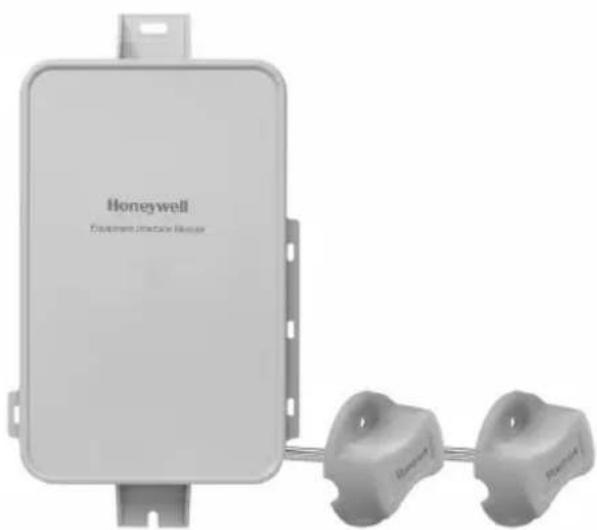
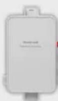
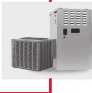
Equipment Interface Module
Installation Guide


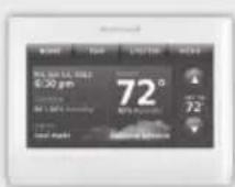
Equipment Interface Module works with:
Prestige IAQ
VisionPRO 8000 with RedLINK
RedLINK to Equipment Interface Module
2 Wires for Power


OR
RedLINK to Equipment Interface Module

REDLINK

Wireless Technology
2 Wires for Power or Battery Only (no wires)
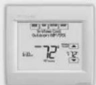
1 Install thermostat
Prestige/VisionPRO with RedLINK: Mount the thermostat and wire to C and R terminals of the Equipment Interface Module (EIM), or to a separate 24 volt transformer (not provided).

NOTE: When the VisionPRO with RedLINK thermostat is used with the EIM, the relays in the thermostat do not function.
(2)
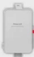
Install equipment interface module
Use screws & anchors as appropriate for the mounting surface. Mount the EIM near the HVAC equipment, or on the equipment itself.
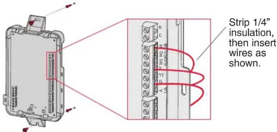

NOTE: If you install more than one thermostat and EIM, the EIMs must be at least 2 feet apart.

NOTE: If you are installing discharge and return air sensors, refer to the mounting instructions in the Alerts and Delta T Diagnostics Installation Instructions packed with the Prestige IAQ kit.
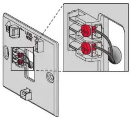
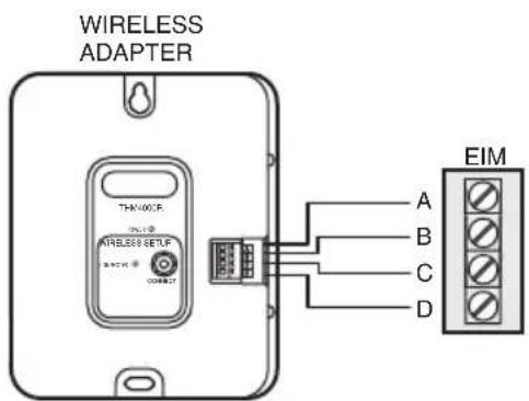
If an EIM is mounted inside a metal cabinet, it is recommended to use a THM4000R1000 Wireless Adapter for extended wireless range. Mount the Wireless Adapter outside the metal cabinet and connect to the ABCD terminals at the EIM.
3 Power optional RedLINK accessories
3.1 Install batteries in RedLINK accessories.
Portable Comfort Control
- Wireless Outdoor Sensor
- Wireless Indoor Sensor
- Wireless Entry/Exit Remote
- Wireless Vent and Filter Boost Remote
- Requires setup. See Installer Setup options in Step 4.5.
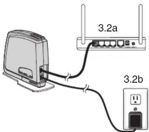
3.2 Connect gateway to internet and connect to power.
3.2a Connect RedLINK Internet Gateway to router or modem with Ethernet cable (RJ45).
3.2b Connect gateway's power cord to an electrical outlet that is not controlled by a wall switch.
Performing initial setup
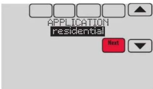
Initial setup options define the type of system you are installing:
Residential or commercial
Non-zoned or zoned
4.1 Follow prompts on the screen to select appropriate options.

4.2 Link the thermostat to the equipment interface module.
4.2a Press and quickly release the CONNECT button on the EIM. Make sure the "Connected" light is flashing green.
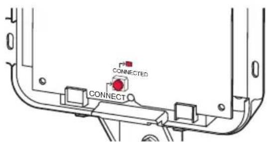
NOTE: If the "Connected" light does NOT flash green, another system may be in the listening mode. Please exit the listening mode at the other system and then try again.
- Green Flashing: In Listening Mode - system is ready to add RedLINK devices.
- Green Steady: RedLINK devices are communicating.
- Red: RedLINK device(s) are NOT communicating. Check EIM and RedLINK devices.
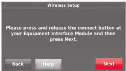
4.2b While the "Connected" light is flashing green on the EIM, press NEXT on the thermostat. After a short delay, the screen will show the thermostat is connected.
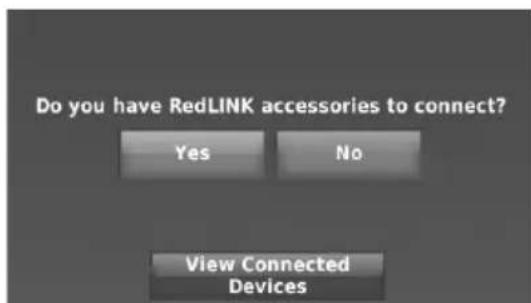
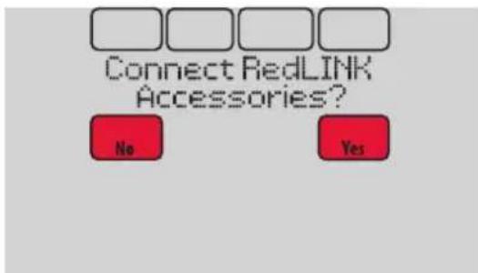
4.3 When you see the prompt Do you have RedLINK accessories to connect? Touch YES or NO.
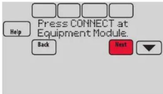
- If you select YES, you will be prompted to Press Connect on all new accessories. Continue to Step 4.4.
If you select NO, continue to Step 4.5.
4.4 Connect each RedLINK accessory.

NOTE: Make sure accessories are at least 2 feet away from the EIM during the linking process.
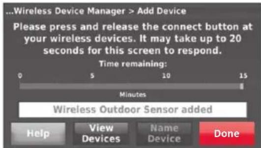
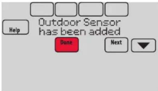
4.4a While the Add Device screen is displayed (listening mode), press and quickly release the CONNECT button on each new RedLINK accessory.
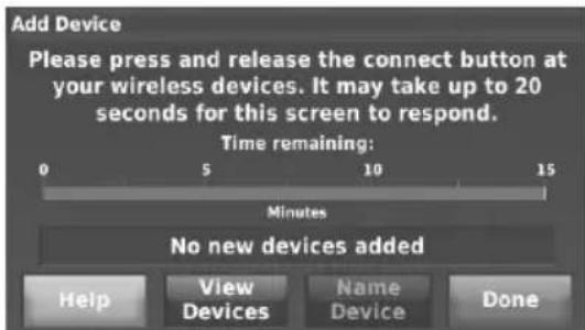
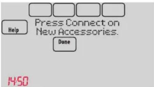
4.4b After a short delay (up to 20 seconds), check the thermostat to confirm the connection of each RedLINK accessory.
4.4c Touch DONE at the thermostat after all new RedLINK accessories are connected.

NOTE: The thermostat displays a countdown timer while in listening mode. If it detects no activity for 15 minutes, it exits listening mode.
4.5 Finish the initial setup.
Finish the setup by selecting the desired options. Touch DONE after you select the last option you want to change.
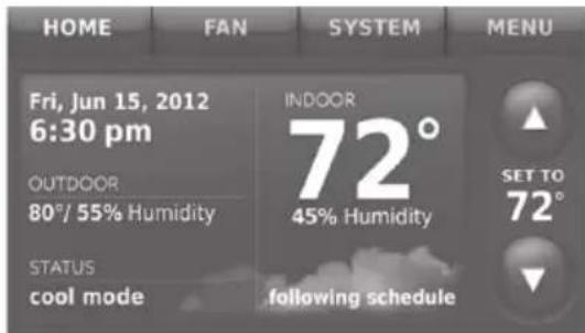
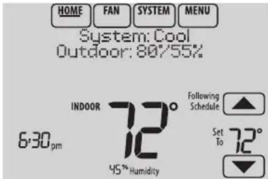
The thermostat now displays its Home screen and the thermostat setup is complete.
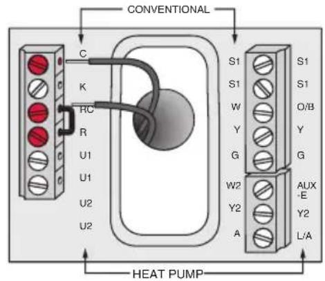
EIM wiring guide — conventional systems
Typical wiring of a conventional system with up to 3-stage heat and 2-stage cool with one transformer.
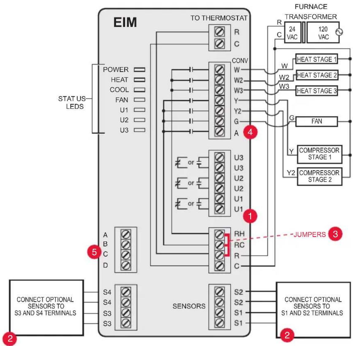
See guides on following pages for thermostat wiring and geothermal radiant heat wiring.
2 Wire a maximum of 4 sensors using the S1-S4 terminals. S1-S4 terminals can be connected to an indoor sensor, outdoor sensor, discharge sensor, return sensor, dry contact device to display an alert or an occupancy sensor for remote setback.
3 Remove jumper(s) if using separate transformers.
4 See Economizer wiring section.
5 Connect wireless adapter to ABCD for extended wireless range.
NOTE: See following pages for additional thermostat wiring guidelines for heat pumps, geothermal systems and optional Economizer.
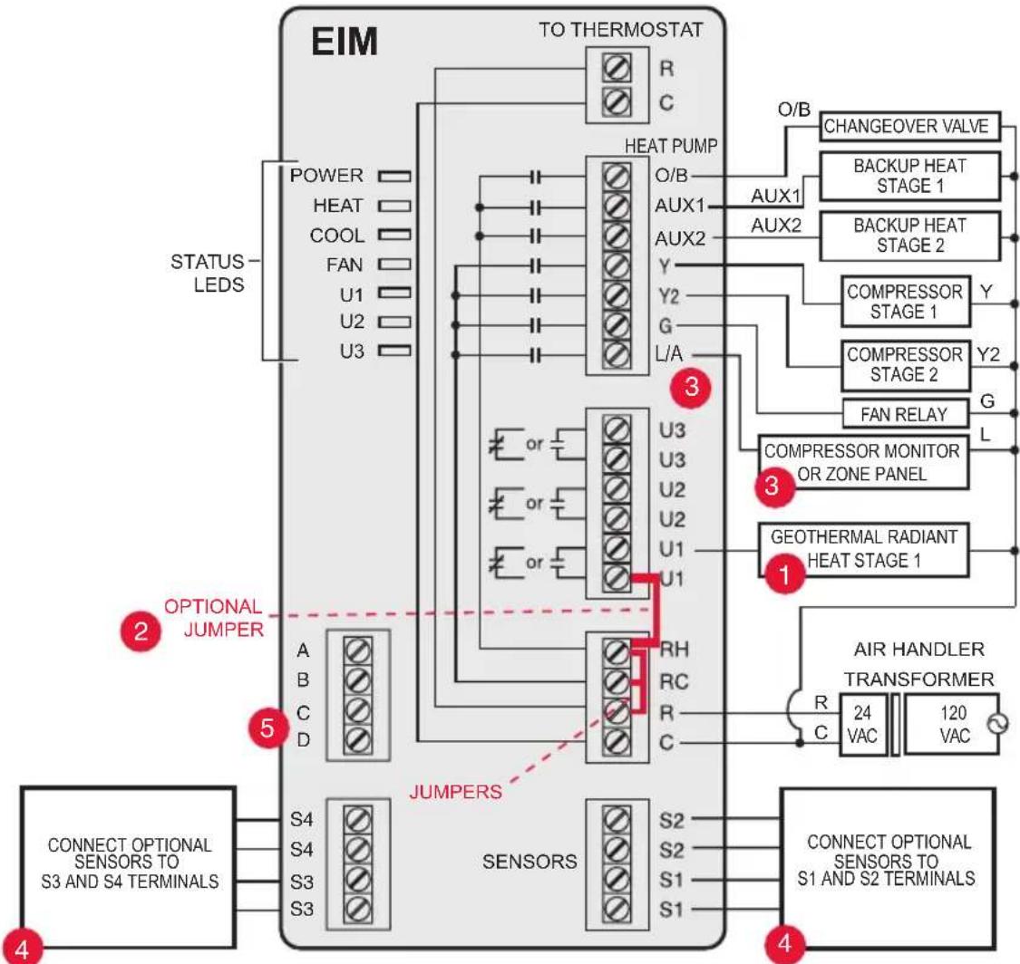
EIM wiring guide — heat pump systems
Typical wiring of a heat pump system with up to four-stage heat and two-stage cool with one transformer.
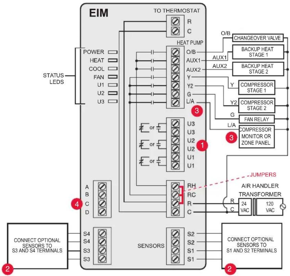
See guides on following pages for thermostat wiring and geothermal radiant heat wiring.
2 Wire a maximum of 2 sensors using the S1-S4 terminals. S1-S4 terminals can be connected to an indoor sensor, outdoor sensor, discharge sensor, return sensor, dry contact device to display an alert or an occupancy sensor for remote setback.
3 L/A terminal sends continuous output when thermostat is set to EM HEAT mode, except when set up for Economizer or TOD. See Economizer wiring section.
4 Connect wireless adapter to ABCD for extended wireless range.
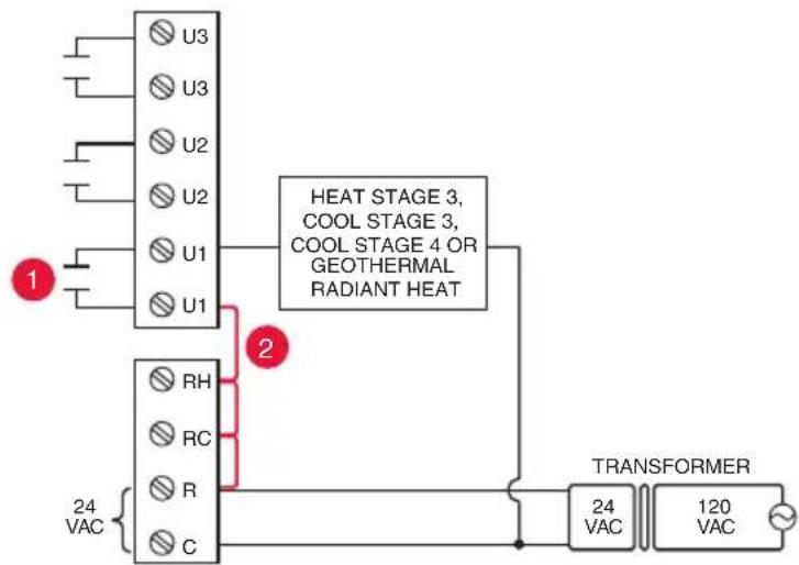
EIM wiring guide — geothermal radiant heat
Typical wiring for geothermal radiant heat, geothermal forced-air, and backup heat with one transformer.
U1, U2 or U3 terminals must be used for geothermal radiant heat. Thermostat allows 2 stages of radiant heat—geothermal (stage 1) and boiler (stage 2).
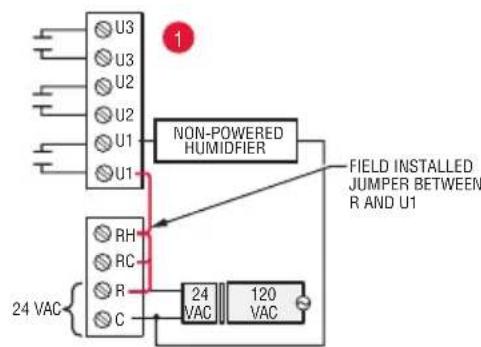
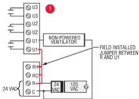
“U” terminals are normally open dry contacts when set up for geothermal radiant heat. You must install a field jumper if radiant heat is powered by system transformer. Do NOT install a field jumper if radiant heat has its own transformer.
3 L/A terminal sends continuous output when thermostat is set to EM HEAT mode except when set up for Economizer or TOD. See Economizer wiring section.
4 Wire a maximum of 2 sensors using the S1-S4 terminals. S1-S4 terminals can be connected to an indoor sensor, outdoor sensor, discharge sensor, return sensor, dry contact device to display an alert or an occupancy sensor for remote setback.
5 Connect wireless adapter to ABCD for extended wireless range.
Using universal relays to control heating or cooling
U1/U2/U3 terminals are normally open dry contacts when set up for a stage of heating or cooling.
2 You must install a field jumper if the stage of heating or cooling is powered by system transformer. Do NOT install a field jumper if the stage of heating has its own transformer.
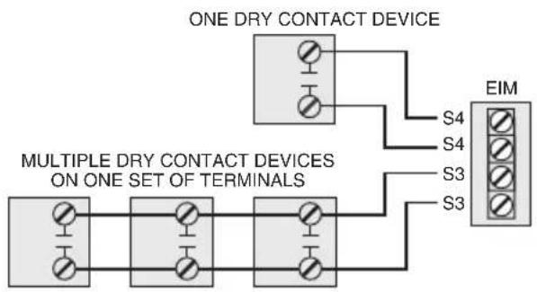
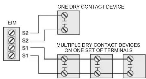
Dry contact alerts

EQUIPMENT DAMAGE HAZARD. Do not apply power to S1-S4 terminals. Do not connect a temperature sensor to the S1-S4 terminals if set for a dry contact device.

NOTE: The dry contact device must be rated for low voltage.
If you are not using the S1-S4 terminals on the EIM, you can connect them to a dry contact device to display an alert. Dry contact alerts include Full Drain Pan, Dirty Filter, Water Leak, System Shutdown, Service Needed, Fan Failure and Custom Alert. Dry contact device can be normally open (shown in diagram) or normally closed.

NOTE: You can connect multiple Dry Contact devices in parallel to the S1-S4 terminals.
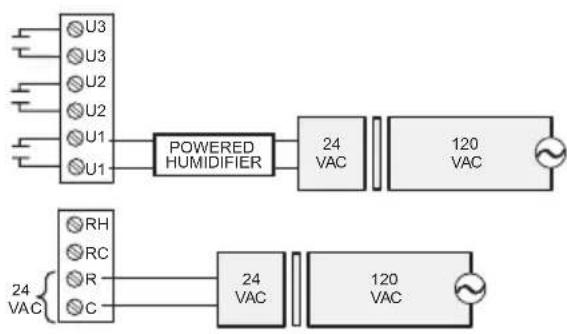
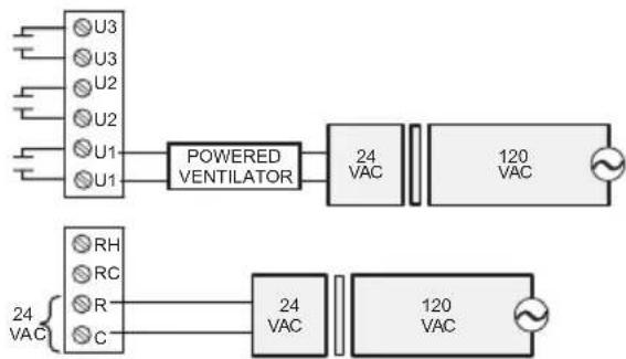
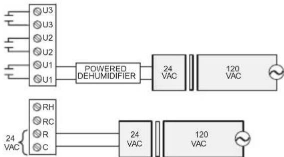
Wiring humidification, dehumidification and ventilation
"U" terminals can be used for humidification, dehumidification or ventilation.
Typical hookup of powered humidifier
Typical hookup of non-powered humidifier
Typical hookup of powered ventilation
Typical hookup of non-powered ventilation
Typical hookup of powered dehumidifier (whole house dehumidifer)
Typical hookup of variable speed blower for dehumidification in low speed
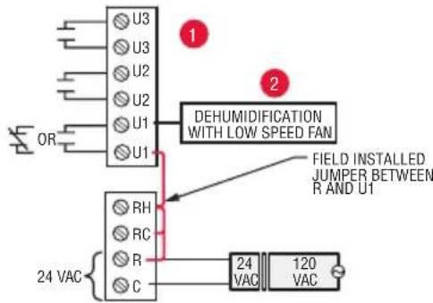
Any combination of universal relays (U1, U2, U3) can be used. They are set in the thermostat installer setup.
2 Wire the universal EIM relay to the low speed fan for dehumidification control at the equipment. The EIM relay can be set to be normally open or normally closed in the thermostat installer setup.

Normally open, dry contacts

Normally closed, dry contacts
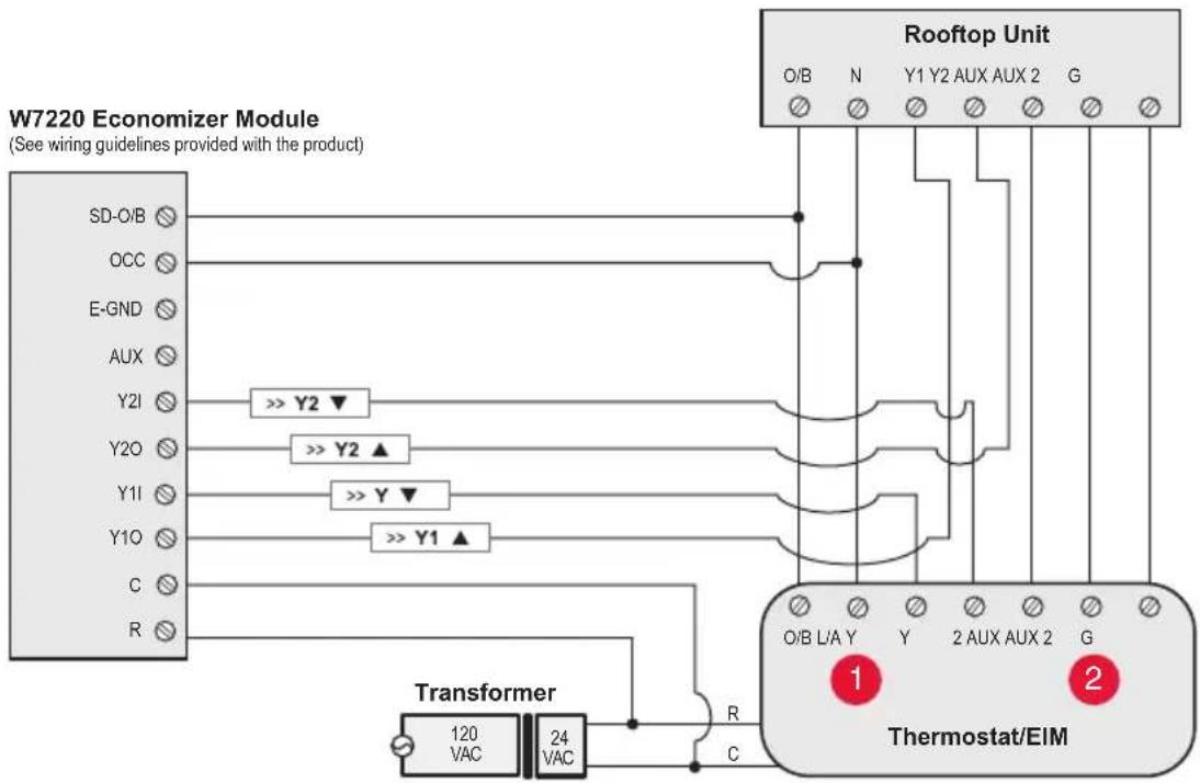
Economizer Module wiring guides
Typical wiring of a W7220 Economizer Module for a heat pump system, using a VisionPRO with RedLINK thermostat or Equipment Interface Module.
Typical wiring of a W7220 Economizer Module for a conventional system, using a VisionPRO with RedLINK thermostat or Equipment Interface Module.
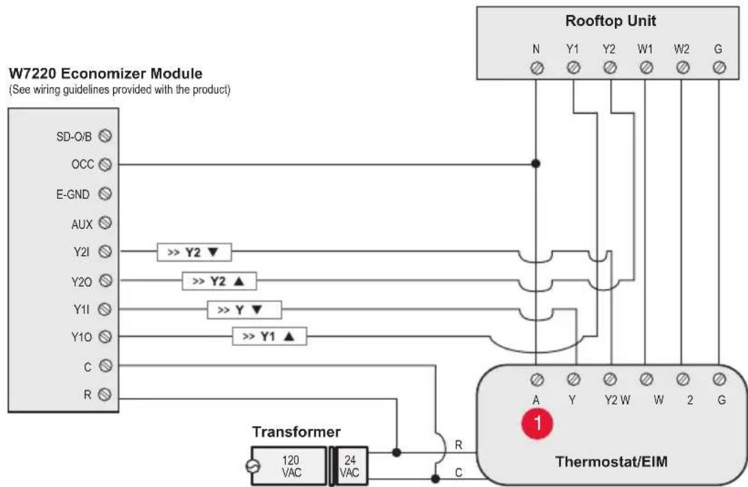
" A ^ 日 or "L/A" terminal must be configured for Economizer in the installer setup. These terminals are powered by the cooling transformer (Rc terminal).
2 Terminal AUX 2 is present only on the Equipment Interface Module.
Economizer Module wiring guides
Typical wiring of a W7213/W7214 Economizer Module for a heat pump system, using a VisionPRO with RedLINK thermostat or Equipment Interface Module.
Typical wiring of a W7212 Economizer Module for a conventional heating system, using a VisionPRO with RedLINK thermostat or Equipment Interface Module.
" A ^ 日 or "L/A" terminal must be configured for Economizer in the installer setup. These terminals are powered by the cooling transformer (Rc terminal).
2 Terminal AUX 2 is present only on the Equipment Interface Module.
To replace the Equipment Interface Module (EIM)
When you replace an EIM, you must reset the RedLINK accessories before connecting them to the new thermostat. Follow the instructions below:
At the Portable Comfort Control:
Press and hold the blank space (or arrow) in the lower right hand corner of the screen until the display changes (hold for about 4 seconds). Press REMOVE, then YES to disconnect from the old thermostats. To reconnect the thermostat, go to Step 4.
At the Indoor Sensor, RedLINK Internet Gateway, Entry/Exit Remote, Vent-Filter Boost Remote or TrueSTEAM Wireless Adapter:
Press and hold the CONNECT button on the accessory until the status light glows amber (hold for about 10 seconds). To reconnect the thermostat, go to Step 4.
At the thermostat:
Go to Installer Options, Wireless Device Manager, Remove Device, and Select This Thermostat. Follow the prompts on the screen to connect the thermostat to the new EIM.
Specifications and replacement parts
Control for up to 4 Heat/2 Cool heat pump systems or up to 3 Heat/2 Cool conventional systems for residential and commercial applications.
Operating Ambient Temperature
Equipment Interface Module: -40 to 165^ F (-40 to 74^ C)
Operating Relative Humidity
Equipment Interface Module: 5% to 95% (non-condensing)
Physical Dimensions (height, width, depth)
Equipment Interface Module: 9-5/16 x 4-13/16 x 1-19/32 inches (91 x 147 x 42 mm)
Electrical ratings
| Terminal Voltage (50/60 Hz) Max. Current Rating | ||
| W - OB 18 to 30 VAC and 750 mVDC 1.00A | ||
| Y (cooling) 18 to 30 VAC 1.00A | ||
| G (fan) 18 to 30 VAC 0.50A | ||
| W2 - Aux 1 (heating) 18 to 30 VAC 0.60A | ||
| Y2 (cooling) 18 to 30 VAC 0.60A | ||
| W3 - Aux 2 | 18 to 30 VAC 1.00A | |
| A-L/A (output) | 18 to 30 VAC 1.00A | |
| U1, U1 30 VAC max. | 0.50A | |
| U2, U2 30 VAC max. | 0.50A | |
| U3, U3 30 VAC max. | 0.50A | |
| Accessories / Replacement Parts Part Number | |
| Equipment Interface Module THM5421R1021 | |
| RedLINK Internet Gateway THM6000R1002 | |
| Wireless Entry/Exit Remote REM1000R1003 | |
| Wireless Vent and Filter Boost Remote HVC20A1000 | |
| Portable Comfort Control REM5000R1001 | |
| Occupancy Sensor for Remote Setback WSK-24 | |
| Wireless Outdoor Sensor C7089R1013 | |
| Wireless Indoor Sensor C7189R1004 | |
| Wireless Outdoor Sensor 10k ohm NTC C7089U1006 | |
| Wired Wall-mount Indoor Sensor 10k ohm NTC C7189U1005 | |
| Wired Flush-mount Indoor Sensor 20k ohm NTC C7772A1004, C7772A1012 | |
| Wired Wall-mount Indoor Sensor 20k ohm NTC TR21 | |
| Wired Wall-mount Indoor Sensor 10k ohm NTC TR21-A | |
| Supply or Return Air Sensor 10k ohm NTC C7735A1000 | |
| Supply or Return Air Sensor 20k ohm NTC C7041 | |
| Supply or Return Air Sensor 20k ohm NTC C7770A1006 | |
| Cover Plate (covers marks left by old thermostats) 50028399-001 | |
| Wireless Adapter for TrueZone, TrueSteam, or extended wireless range | THM4000R1000 |
Regulatory information
FCC Compliance Statement (Part 15.19) (USA only):
This device complies with Part 15 of the FCC Rules. Operation is subject to the following two conditions:
1 This device may not cause harmful interference, and
2 This device must accept any interference received, including interference that may cause undesired operation.
FCC Warning (Part 15.21) (USA only):
Changes or modifications not expressly approved by the party responsible for compliance could void the user's authority to operate the equipment.
FCC Interference Statement (Part 15.105 (b)) (USA only):
This equipment has been tested and found to comply with the limits for a Class B digital device, pursuant to Part 15 of the FCC Rules. These limits are designed to provide reasonable protection against harmful interference in a residential installation. This equipment generates uses and can radiate radio frequency energy and, if not installed and used in accordance with the instructions, may cause harmful interference to radio communications. However, there is no guarantee that interference will not occur in a particular installation. If this equipment does cause harmful interference to radio or television reception, which can be determined by turning the equipment off and on, the user is encouraged to try to correct the interference by one of the following measures:
- Reorient or relocate the receiving antenna.
- Increase the separation between the equipment and receiver.
- Connect the equipment into an outlet on a circuit different from that to which the receiver is connected.
- Consult the dealer or an experienced radio/TV technician for help.
Equipment interface module, thermostats and outdoor sensor:
To comply with FCC and Industry Canada RF exposure limits for general population/ uncontrolled exposure, the antenna(s) used for these transmitters must be installed to provide a separation distance of at least 20~cm from all persons and must not be colocated or operating in conjunction with any other antenna or transmitter.
Portable Comfort Control:
This portable transmitter with its antenna complies with FCC and Industry Canada RF exposure limits for general population/uncontrolled exposure. This device must not be co-located or operating in conjunction with any other antenna or transmitter.
Section 7.1.2 of RSS-GEN:
Under Industry Canada regulations, this radio transmitter may only operate using an antenna of type and maximum (or lesser) gain approved for the transmitter by Industry Canada. To reduce potential radio interference to other users, the antenna type and its gain should be so chosen that the equivalent isotropically radiated power (e.i.r.p.) is not more than that necessary for successful communication.
Section 7.1.3 of RSS-GEN:
Operation is subject to the following two conditions:
1 This device may not cause interference, and
2 This device must accept any interference, including interference that may cause undesired operation of the device.

DISCONNECT POWER BEFORE INSTALLATION. Can cause electrical shock or equipment damage.

Must be installed by a trained, experienced technician. Read these instructions carefully. Failure to follow these instructions can damage the product or cause a hazardous condition.
Need Help?
For assistance please visit http://customer.honeywell.com, or call toll-free: 1-800-468-1502 (residential installation) • 1-888-245-1051 (commercial installation)
Automation and Control Systems
Honeywell International Inc.
1985 Douglas Drive North
Golden Valley, MN 55422
http://customer.honeywell.com
Honeywell
U.S. Registered Trademark. © 2012 Honeywell International Inc. 69-2758EFS—01 M.S. 11-12 Printed in U.S.A.
REDLINK
Wireless Technology

69-2758EFS-01
Honeywell International Inc.
1985 Douglas Drive North
Golden Valley, MN 55422
http://customer.honeywell.com
Honeywell