
ADS82H - Speaker QSC - Free user manual and instructions
Find the device manual for free ADS82H QSC in PDF.
| Brand | QSC Audio Products |
| Model | ADS82H |
| Product Type | All-weather multi-purpose two-way full-range speaker |
| Category | Sound reinforcement (SR) speaker |
| Coverage Angles | 90° horizontal x 60° vertical (adjustable by rotating waveguide) |
| Enclosure Materials | Impact-resistant polystyrene |
| Grille Type | Removable grille, paintable |
| Input Connectors | + (red) and - (black) terminals |
| Nominal Impedance | 8 ohms |
| Compatible Optional Mounting Hardware | ID-8 / ID-8T IntelliDock, YM-8 / YM-8T Yoke Mount |
| Integrated Transformer (option) | Available on ID-8T and YM-8T (70 V / 100 V) |
| Safety Cable Attachment Point | Rear of speaker, near base |
| Warranty | 3-year limited (USA) |
| Maintenance | Clean with a dry cloth |
| Painting | Possible on enclosure and grille (specific procedure) |
| Outdoor Use | Yes, all-weather |
| Polarity | Marked + and - terminals, observe polarity for best low-frequency response |
| Repairability | Refer to qualified personnel; spare parts available from QSC |
Frequently Asked Questions - ADS82H QSC
User questions about ADS82H QSC
0 question about this device. Answer the ones you know or ask your own.
Ask a new question about this device
Download the instructions for your Speaker in PDF format for free! Find your manual ADS82H - QSC and take your electronic device back in hand. On this page are published all the documents necessary for the use of your device. ADS82H by QSC.
USER MANUAL ADS82H QSC
natural_image
Line drawing of a white cylindrical device with a lid and ventilation slots (no text or symbols)User Manual
EN
Manual del Usuario
ES
IMPORTANT SAFETY PRECAUTIONS
& EXPLANATION OF SYMBOLS
1- Read these instructions.
2- Keep these instructions.
3- Heed all warnings.
4- Follow all instructions.
5- Clean only with a dry cloth.
6- Install in accordance with QSC Audio Product's instructions and a licensed, professional engineer.
7- Do not install near any heat sources such as radiators, heat registers, stoves, or other apparatus (including amplifiers) that produce heat.
8- Only use attachments/accessories from QSC Audio Products, Inc.
9- Use only with mounts or brackets specified by QSC Audio Products.
10- Refer all servicing to qualified personnel. Servicing is required when the apparatus has been damaged in any way.

The lightning flash with arrowhead symbol within an equilateral triangle is intended to alert the user to the presence of uninsulated "dangerous" voltage within the product's enclosure that may be of sufficient magnitude to constitute a risk of electric shock to humans.

The exclamation point within an equilateral triangle is intended to alert the user to the presence of important operating and maintenance (servicing) instructions in this manual.

WARNING! Before placing, installing, rigging, or suspending any speaker product, inspect all hardware, suspension, cabinets, transducers, brackets and associated equipment for damage. Any missing, corroded, deformed or non-load rated component could significantly reduce the strength of the installation, placement, or array. Any such condition severely reduces the safety of the installation and should be immediately corrected. Use only hardware which is rated for the loading conditions of the installation and any possible short-term unexpected overloading. Never exceed the rating of the hardware or equipment. Consult a licensed, professional engineer when any doubt or questions arise regarding a physical equipment installation.
Warranty (USA only; other countries, see your dealer or distributor)
Disclaimer
QSC Audio Products, Inc. is not liable for any damage to amplifiers, or any other equipment that is caused by negligence or improper installation and/or use of this loudspeaker product.
QSC Audio Products 3 Year Limited Warranty
QSC Audio Products, Inc. ("QSC") guarantees its products to be free from defective material and / or workmanship for a period of three (3) years from date of sale, and will replace defective parts and repair malfunctioning products under this warranty when the defect occurs under normal installation and use - provided the unit is returned to our factory or one of our authorized service stations via pre-paid transportation with a copy of proof of purchase (i.e., sales receipt). This warranty provides that the examination of the return product must indicate, in our judgment, a manufacturing defect. This warranty does not extend to any product which has been subjected to misuse, neglect, accident, improper installation, or where the date code has been removed or defaced. QSC shall not be liable for incidental and/or consequential damages. This warranty gives you specific legal rights. This limited warranty is freely transferable during the term of the warranty period.
Customer may have additional rights, which vary from state to state.
In the event that this product was manufactured for export and sale outside of the United States or its territories, then this limited warranty shall not apply. Removal of the serial number on this product, or purchase of this product from an unauthorized dealer, will void this limited warranty.
Periodically, this warranty is updated. To obtain the most recent version of QSC's warranty statement, please visit www.qscaudio.com.
Contact us at 800-854-4079 or visit our website at www.qscaudio.com.
© Copyright 2003, 2005, QSC Audio Products, Inc.
QSC® is a registered trademark of QSC Audio Products, Inc.
"QSC" and the QSC logo are registered with the U.S. Patent and Trademark Office
All trademarks are the property of their respective owners.
Introduction
Thank you and congratulations on your purchase of the Acoustic Design AD-S82 Multi-Use, All-Weather Loudspeakers. These products represent the state-of-the-art in all-weather, lightweight SR (sound reinforcement) loudspeaker systems. To get the most from your investment, we encourage you to review this manual carefully.
The AD-S82 loudspeaker systems are full range, high output, two-way designs delivering superior sound quality and high SPL in a lightweight, all-weather enclosure. These loudspeakers make an excellent choice for a wide variety of SR applications.
Coverage Angles
Before mounting the loudspeaker, determine the mounting orientation and desired coverage angles. As supplied from the factory, the loudspeaker's coverage angles are 90^ (horizontal) x 60^ (vertical) with the cabinet oriented vertically. The waveguide can be rotated to interchange the coverage angles.
Rotating the Waveguide to Alter HF Coverage Pattern
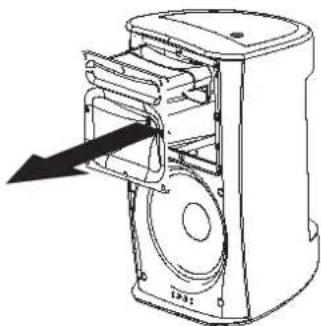
1- Remove the grill. Gently and evenly work the grill out of its retaining groove to avoid bending the grill.
2- Remove the eight waveguide retaining screws. A #2-size Phillips screwdriver is recommended.
3- Reach into the waveguide's port and pull gently to remove the waveguide. Be careful not to damage the connections, wiring, or the gasket between the waveguide and the cabinet.
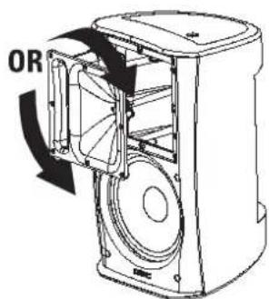
4- Rotate the horn 90^ clockwise or counterclockwise and set it back in place. Make certain the wiring is not stressed or pulled loose from its connections when rotating the assembly.
5- Before reinstalling the waveguide screws, lift the assembly a small distance and make sure that the gasket is properly in place. Reposition it, if required. Set the waveguide in place and install the screws. Do not overtighten.
6- Replace the grill.
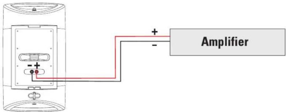
Connection
natural_image
Technical line drawing of a mechanical device with internal components and an arrow indicating direction (no text or symbols)EN
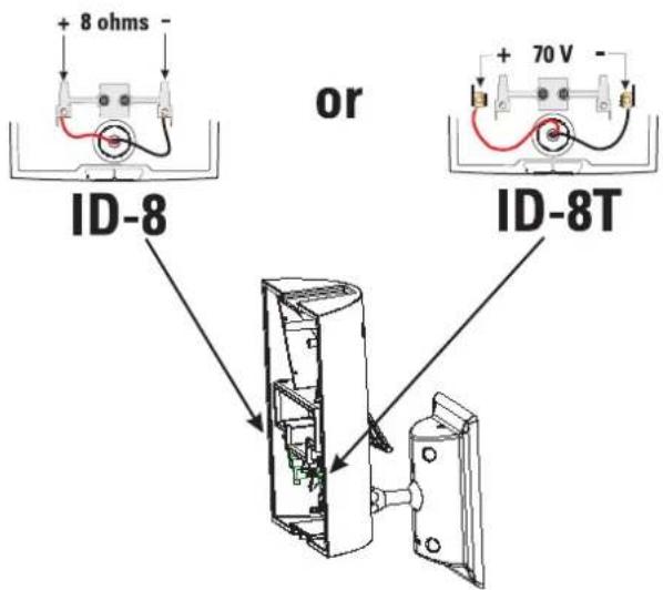
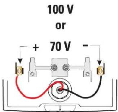
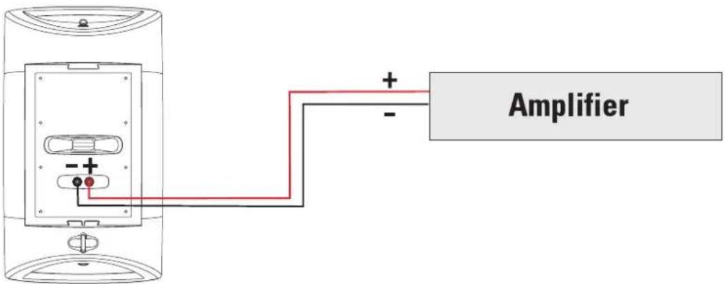
Connect the amplifier's + and - outputs directly to the loudspeaker's + (red) and - (black) terminals. If using optional ID-8 or YM-8 mounting hardware, refer to the instructions provided with the hardware.
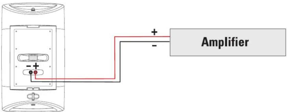

Maintain proper speaker and amplifier connection polarity throughout the entire system. All positive-marked loudspeaker terminals should be connected to positive-marked amplifier output terminals. This will provide the best possible low-frequency output from your system.
Mounting
If using the loudspeaker only (no optional mount), the loudspeaker can be set on any appropriate surface. The cabinet will lean back at a slight angle when set on a flat surface.
When operated at high output levels, the cabinet can generate sufficient vibration, causing the cabinet to move or creep if set on a hard surface. Use anti-slip matting under the cabinet or self-adhesive rubber feet to keep the cabinet from creeping.
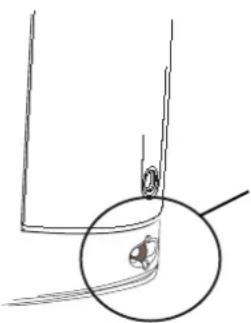
On the back of the loudspeaker, near the bottom, is a safety cable attachment point. Install a safety cable strong enough to support several times the weight of the loudspeaker assembly in the event it may fall. The cable must be secured to a secondary support point which is also strong enough to support several times the loudspeaker's weight.

IMPORTANT! ENSURE THAT THE LOUDSPEAKER IS MOUNTED PROPERLY AND A SAFETY CABLE IS INSTALLED TO RETAIN THE LOUDSPEAKER IN THE EVENT OF A MOUNTING FAILURE.
natural_image
Simple line drawing of a mechanical component with a circular inset showing a small feature (no text or symbols)Ensure the mounting surface and supporting structure are appropriately strong enough to support the loudspeaker assembly and any potential vibration or seismic activity.
Attach a safety cable to the attachment point on the bottom-back of the loudspeaker. Ensure the safety cable, cable attachment technique, securing hardware, and attachment points are strong enough to support several times the weight of the loudspeaker in the event of a primary-mount failure.
Optional Mounts Available
ID-8 and ID-8T IntelliDock™ Mounts (YM-8 models, see p.6)
This mount features a quick-connect/disconnect latch which provides electrical connections and a highly-adjustable ball-type mount. This mount allows for all mounts and wiring to be fully installed and the loudspeakers to be placed at the last possible moment.
A security retaining screw for the latch in included, making speaker removal impossible without the correct Allen (hex) bit to remove the screw. The IntelliDock mount and its wiring feed-through bushing provide maximum weather resistance and maximum acoustic coverage range adjustment.
The ID-8T is identical to the ID-8, but equipped with an audio matching transformer with 70V and 100V distributed audio input capability.
Refer to the instructions included with the mount for detailed information.
natural_image
Technical line drawing of a mechanical assembly with internal components (no text or symbols)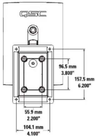
Optional ID-8 and ID-8T Mounting Procedure
natural_image
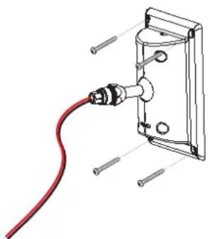
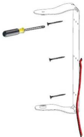
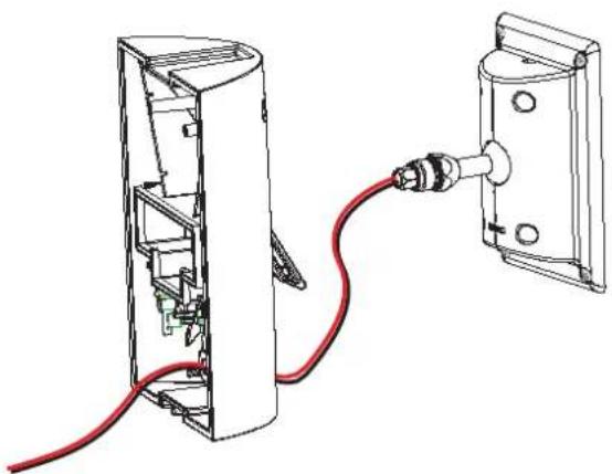
Technical line drawing of a cable inserted into a wall-mounted electrical outlet (no text or symbols)1- Secure the ball mount bracket to the mounting surface. The adapter plate can be removed if desired, however, we recommend its use. Ensure the mounting surface and supporting structure are appropriately strong enough to support the loudspeaker assembly and any potential vibration or seismic activity.

natural_image
Technical line drawing of a device with red cable and connector, showing internal components (no text or symbols)2- Feed the speaker wire through the cover. Secure the cover to the ball-mount assembly.
Optional ID-8 and ID-8T Mounting Procedure (continued)

3- Choose the appropriate rubber sealing gasket and thread the speaker wire through it. Make sure the tapered side of the gasket is toward the cover. Push the gasket into its seat, and thread the nut over the speaker wire and tighten.
4- Trim the wires to the appropriate length. Strip the wires and secure them to the terminals.
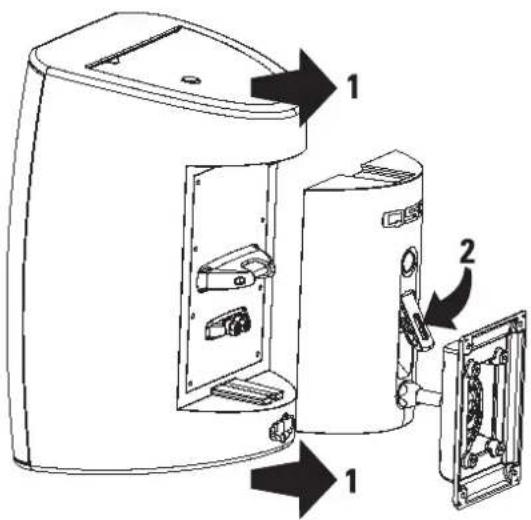
5- With the latch open, align the loudspeaker with the IntelliDock and slide the loudspeaker into place. Push the latch down until in engages with the locking tab.
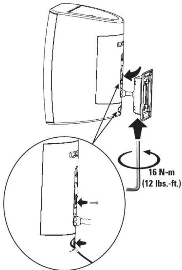
6- Aim the loudspeaker in the desired direction and tighten the Allen (hex) retaining screw using the tool provided. Snug the bolt then tighten exactly 5/8 of a turn (225° rotation) to positively secure the ball-mount. If a torque wrench and appropriate hex bit are available, tighten the bolt to 16 N-m (12 lbs-ft). If extra theft deterrence is required, install the provided security screw. Attach a safety cable to the loudspeaker's safety cable attachment point.
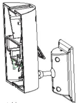
Optional YM-8 and YM-8T Yoke Mounts
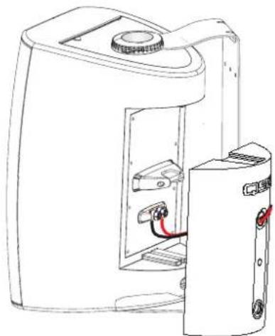
The YM-8 and YM-8T yoke mounts provide for mounting on most any surface and are adjustable on one axis. A cover plate is provided for the loudspeaker's rear recess and is secured with a retaining screw. The cover plate has a wiring feed-through hole, complete with rubber grommet and compression nut to prevent water from wicking down the cable and into the electrical connections.
The YM-8T yoke mount's cover plate is equipped with an audio matching transformer with 70V and 100V distributed audio input capability.
Refer to the instructions included with the mount for detailed information.
Optional YM-8 and YM-8T Mounting Procedure
natural_image
Diagram of a screwdriver holding three screws, with a red wire attached to the handle (no text or symbols)1- Secure the yoke bracket to the mounting surface. Ensure the mounting surface and supporting structure are appropriately strong enough to support the loudspeaker assembly and any potential vibration or seismic activity.
natural_image
Technical line drawing of a device casing with internal components and red wiring (no text or symbols)3- Thread the speaker wiring through the cover plate.
natural_image
Line drawing of a device with internal components and directional arrows indicating rotation (no text or symbols)2- Secure the loudspeaker to the yoke bracket.
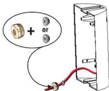
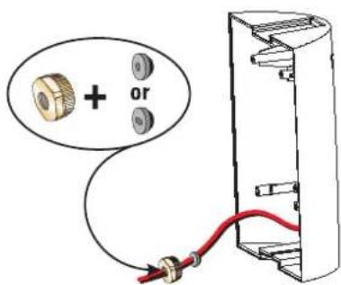
4- Choose the appropriate rubber sealing gasket and thread the speaker wire through it. Make sure the tapered side of the gasket is toward the cover. Push the gasket into its seat, and thread the nut over the speaker wire and tighten.
Optional YM-8 and YM-8T Mounting Procedure (continued)
natural_image
Line drawing of a portable electronic device with internal components and a separate outlet (no text or symbols)5- Strip the speaker wiring ends and connect the wires. If using the YM-8, connect the wires directly to the binding posts. If using the YM-8T, connect the 70V/100V terminals in the cover assembly.
5a- The YM-8T cover assembly is equipped with the 70V/100V matching transformer, a 4-position power selection switch, and all required connections pre-wired. Just connect the speaker wires to the appropriate terminals inside the cover, then install the cover onto the loudspeaker. Cover-to-loudspeaker connections are made by the banana plugs in the YM-8T assembly.
natural_image
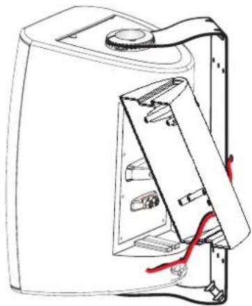
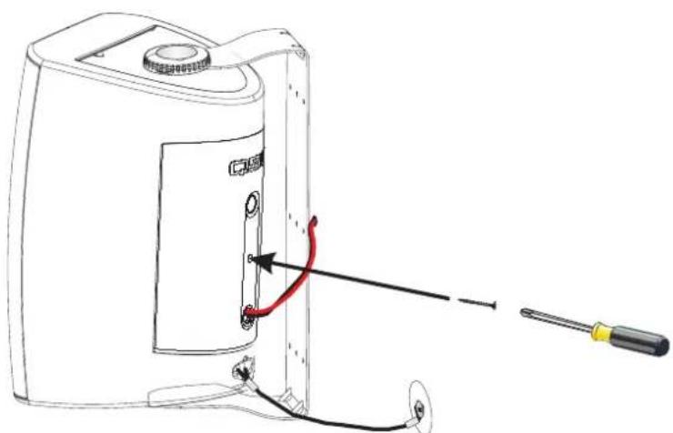
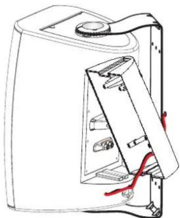
Line drawing of a portable device with a screwdriver inserted, showing internal components and wiring (no text or symbols)6- Align the cover on the back of the loudspeaker and slide into place. The cover is designed to fit only one way. Install the cover retaining screw to prevent the cover from vibrating loose and to keep the connections weather-tight. Attach a safety cable to the attachment point on the bottom-back of the loudspeaker. Ensure the safety cable, cable attachment technique, securing hardware, and attachment points are strong enough to support the weight of the loudspeaker in the event of a primary-mount failure.
natural_image
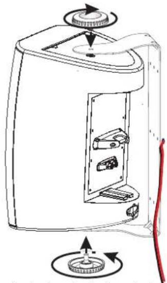
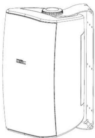
Line drawing of a white industrial air purifier unit with a side-mounted cover and ventilation slots (no text or symbols)7- Rotate the cabinet into the desired position and tighten both of the mounting knobs.

IMPORTANT! PLEASE READ AND ENSURE THAT THE LOUDSPEAKER IS MOUNTED PROPERLY AND A SAFETY CABLE IS INSTALLED TO RETAIN THE LOUDSPEAKER IN THE EVENT OF A MOUNTING FAILURE.
Ensure the mounting surface and supporting structure are appropriately strong enough to support the loudspeaker assembly and any potential vibration or seismic activity.
Attach a safety cable to the attachment point on the bottom-back of the loudspeaker. Ensure the safety cable, cable attachment technique, securing hardware, and attachment points are strong enough to support several times the weight of the loudspeaker in the event of a primary-mount failure.
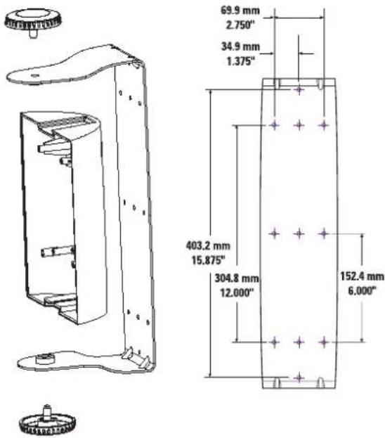
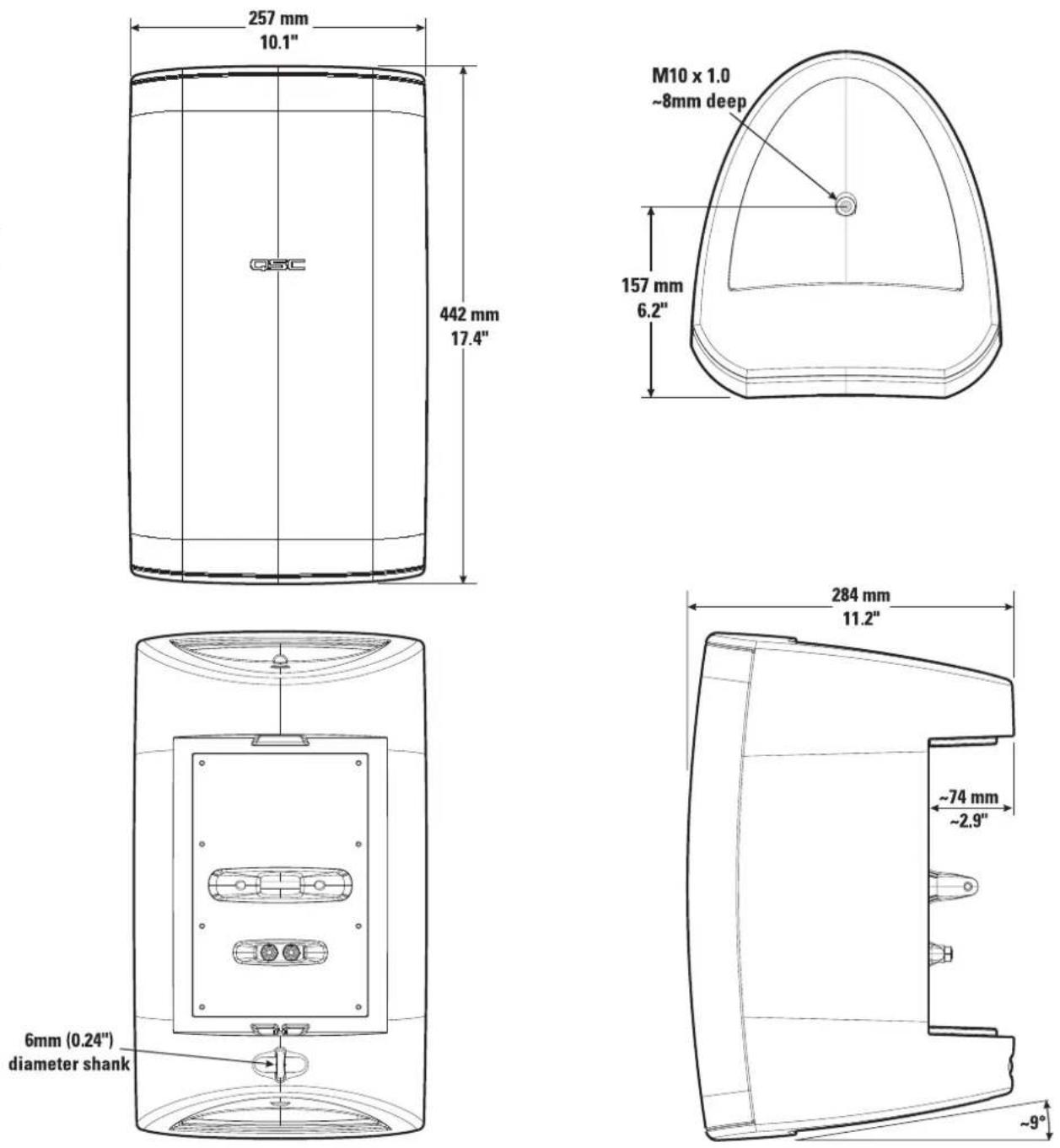
AD-S82 and AD-S82H Loudspeaker Dimensions
EN
Specifications
AD-S82 AD-S82H
Frequency Response: 85-22kHz (-6 dB) 80-21kHz (-6 dB)
55-23kHz (-10dB) 60-22kHz (-10dB)
Maximum Output: 110 dB SPL continuous rms output 113 dB SPL continuous rms output
(calculated) 116 dB SPL peak output 119 dB SPL peak output
Impedance: 8 ohms nominal 8 ohms nominal
6.4 ohms minimum, 240 Hz 7.0 ohms minimum, 210 Hz
25 ohms maximum, 2.5k Hz 135 ohms maximum
Power Rating ^3 :
| rms (IEC 100 hrs): 100 watts rms 200 watts rms | ||
| recommended amp power: | 200 watts rms | 400 watts rms |
| Sensitivity: | 90.0 dB, 1 watt, 1 meter, free field (4 pi) | 90.5 dB, 1 watt, 1 meter, free field (4 pi) |
| Directivity Index: | ||
| 500 Hz | 3.8 | 4.0 |
| 1000 Hz | 5.8 | 5.5 |
| 2000 Hz | 12.6 | 11.7 |
| 4000 Hz | 10.2 | 8.9 |
| 8000 Hz | 9.8 | 8.6 |
| 16000 Hz | 9.7 | 7.2 |
| Q: | ||
| 500 Hz | 2.4 | 2.5 |
| 1000 Hz | 3.8 | 3.6 |
| 2000 Hz | 18.2 | 14.7 |
| 4000 Hz | 10.4 | 7.7 |
| 8000 Hz | 9.5 | 7.3 |
| 16000 Hz | 9.2 | 5.3 |
| Weight: | 16.2 lb. (19.6 lb.) | 16.9 lb. (20.3 lb.) |
(net (shipping))
All Models
Nominal Coverage:
90° horiz. x 60° vert.
Enclosure and Grill:
high impact polystyrene, removable metal grill
Connectors:
binding posts, 19 mm (0.75") spacing, accepts wire and banana plugs
Optional 8 Ohm Mounting Hardware:
QSC IntelliDock mount ID-8 or yoke mount YM-8
Optional 70V/100V Transformer
Equipped Mounting Hardware:
QSC IntelliDock mount ID-8T or yoke mount YM-8T
ID-8T and YM-8T Power and Calculated Continuous Maximum Output (dB SPL) by Tap Selected:
| 70.7V line | 100V line | |
| Tap 1: | 7.5W (99 dB) | 15W (102 dB) |
| Tap 2: | 15W (102 dB) | 30W (105 dB) |
| Tap 3: | 30W (105 dB) | 60W (108 dB) |
| Tap 4: | 60W (108 dB) | n/a |
NOTES:
1- All frequency ranges specified refer to measured free-field response (4 pi).
2- Calculated maximum peak SPL at 1 m, free-field, speaker operating at rated rms power pink noise input, 50 Hz to 20 kHz.
3- Maximum input power tested in accordance with IEC recommendations; 50 Hz to 20 kHz band limiting, 6 dB signal crest factor.
EN
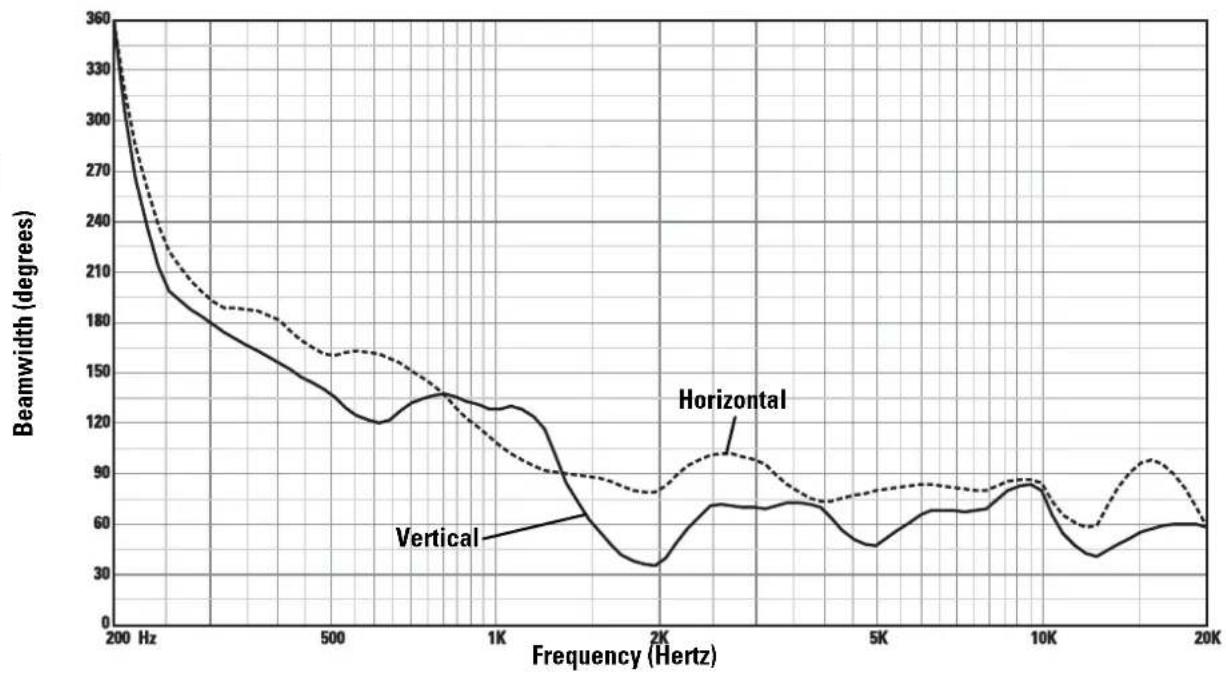
AD-S82 Horizontal and Vertical Beamwidth Vs. Frequency
line
| Frequency (Hertz) | Vertical | Horizontal | Solid Line | | ----------------- | -------- | ---------- | ---------- | | 200 | 360 | 360 | 360 | | 500 | 180 | 160 | 180 | | 1K | 120 | 140 | 120 | | 2K | 30 | 90 | 30 | | 5K | 50 | 80 | 50 | | 10K | 80 | 90 | 80 | | 20K | 60 | 60 | 60 |AD-S82 Response On-Axis, 20° Off-Axis, 40° Off-Axis, and Impedance Vs. Frequency
line
| Frequency (Hz) | SPL (dB) - On Axis | SPL (dB) - 20° Off Axis | SPL (dB) - 40° Off Axis | Impedance (ohms) | | -------------- | ------------------ | ----------------------- | ----------------------- | ----------------- | | 20 | 50 | 50 | 50 | 8 | | 50 | 80 | 80 | 65 | 15 | | 100 | 88 | 88 | 70 | 20 | | 200 | 90 | 90 | 60 | 10 | | 500 | 90 | 90 | 65 | 15 | | 1K | 90 | 90 | 65 | 20 | | 2K | 90 | 90 | 75 | 25 | | 5K | 90 | 90 | 65 | 15 | | 10K | 90 | 90 | 60 | 10 | | 20K | 90 | 90 | 55 | 5 | | 35K | 55 | 55 | 55 | 5 |Specifications are subject to change without notice.
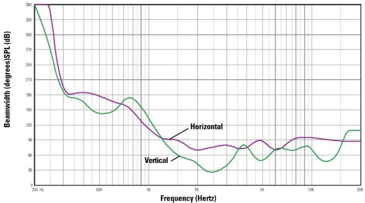
AD-S82H Horizontal and Vertical Beamwidth Vs. Frequency
line
| Frequency (Hertz) | Horizontal | Vertical | | ----------------- | ---------- | -------- | | 200 | 360 | 360 | | 500 | 180 | 140 | | 1K | 100 | 180 | | 2K | 70 | 30 | | 5K | 90 | 50 | | 10K | 90 | 70 | | 20K | 90 | 110 |EN
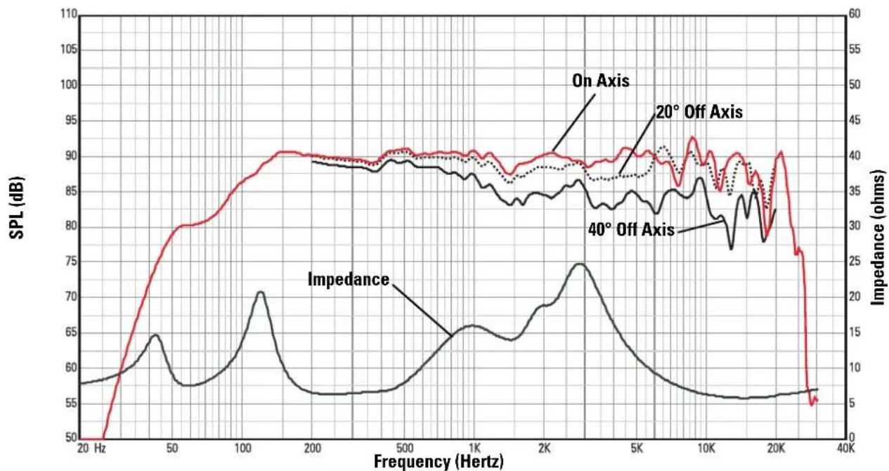
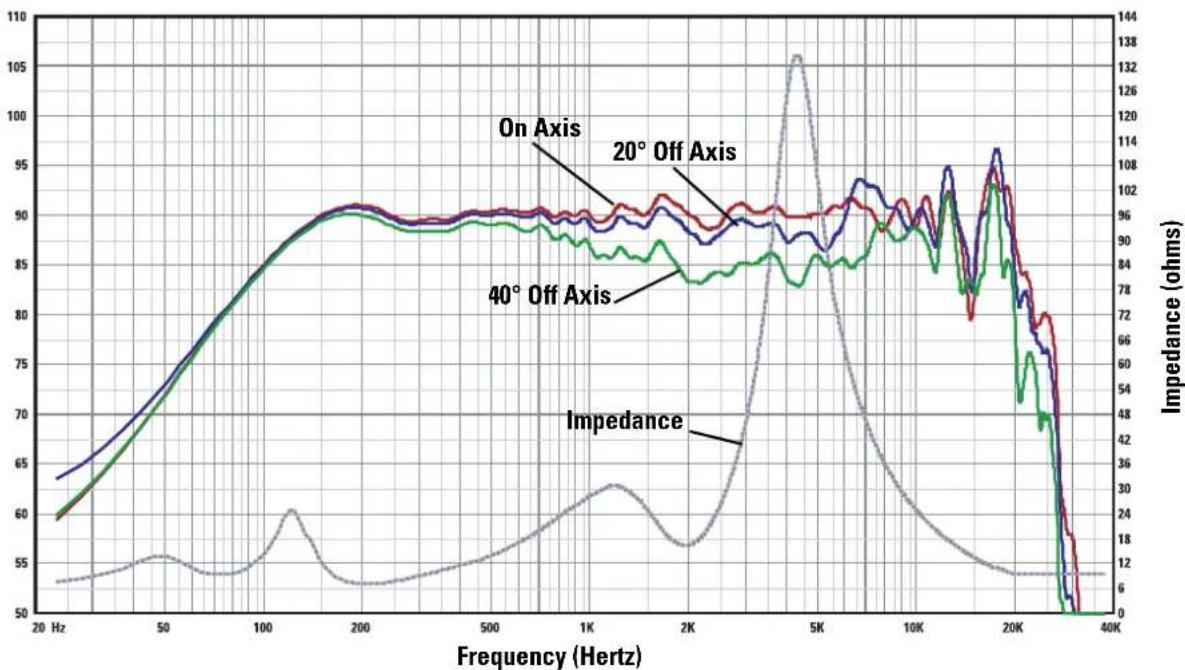
AD-S82H Response On-Axis, 20° Off-Axis, 40° Off-Axis, and Impedance Vs. Frequency
line
| Frequency (Hz) | On Axis | 20° Off Axis | 40° Off Axis | Impedance (ohms) | | -------------- | ------- | ------------ | ------------ | ---------------- | | 20 | 63 | 60 | 59 | 12 | | 50 | 70 | 70 | 70 | 18 | | 100 | 80 | 80 | 80 | 24 | | 200 | 90 | 90 | 90 | 30 | | 500 | 90 | 90 | 90 | 36 | | 1K | 90 | 90 | 90 | 42 | | 2K | 90 | 90 | 90 | 48 | | 5K | 90 | 90 | 90 | 138 | | 10K | 95 | 95 | 95 | 72 | | 20K | 105 | 105 | 105 | 48 | | 40K | 5 | 5 | 5 | 6 |Specifications are subject to change without notice.
Painting the AD-S82(H) Loudspeaker
The loudspeaker enclosure and grill can be painted to match any decor, provided the following precautions are observed. The optional ID-8 IntelliDock and YM-8 yoke mount can also be painted. The cabinet is made of high impact polystyrene which requires controlled painting procedures in order to obtain good results when painting. Use a paint "system" designed for polypropylene from any reputable paint supplier.
1- Remove the grill.
2- If painting mount and loudspeaker as a unit: Attach the ID-8 or YM-8 so that the loudspeaker and mount can be painted as a unit.
3- If painting mount and loudspeaker separately: Mask the loudspeaker's input connector and the ID-8's interior.
4- Mask the woofer, tweeter, and port being certain not to apply tape directly to the drivers. Alternatively, the inside of the grill can be completely masked and set in place on the loudspeaker enclosure for painting.
5- Wash the components to be painted with a mild soap and hot water. Be careful not to get water on or into either of the drivers or the input connections. Rinse with hot water. Allow to dry thoroughly.
6- Scuff-sand the components to be painted using red Scotchbrite® pad or 320 - 400 grit sandpaper.
7- Using compressed air, remove all dust from the components to be painted. Do not blow compressed air directly into either driver.
8- Clean the components to be painted.
9- Using a clean, lint-free, white cloth, wipe the components to be painted with suitable prep solution.
10- Apply adhesion promoter.
11- Apply primer topcoat.
12- Apply paint.
13- Allow to dry for at least 8 hours before handling.
natural_image
Technical line drawing of a mechanical device with internal components and an arrow indicating direction (no text or symbols)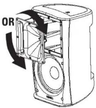

natural_image
Simple line drawing of a mechanical joint or bracket with a circular inset showing a small object (no text or symbols)natural_image
Technical line drawing of a mechanical assembly with internal components (no text or symbols)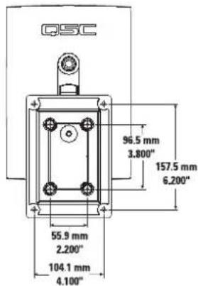
natural_image
Technical line drawing of a cable inserted into a wall socket with screws, no text or symbols presentnatural_image
Technical line drawing of a device with red cable and connector, showing internal components (no text or symbols)natural_image
Diagram of a screwdriver holding three screws, with a red cable inserted (no text or symbols)natural_image
Technical line drawing of a device casing with internal components and wiring (no text or symbols)natural_image
Line drawing of a device with labeled components and directional arrows indicating rotation (no text or symbols)natural_image
Line drawing of a portable electronic device with internal components and a separate panel (no text or symbols)natural_image
Line drawing of a device with a red curved arrow indicating a cable or adjustment, connected to a screwdriver (no text or symbols present)natural_image
Line drawing of a rectangular industrial device with a circular top and side connectors (no text or symbols)natural_image
Technical line drawing of a mechanical device with an arrow indicating a component or insertion (no text or symbols present)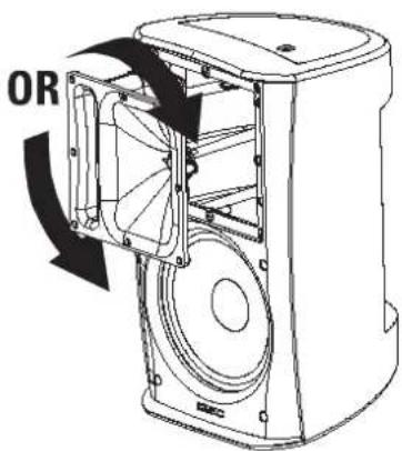

natural_image
Simple line drawing of a mechanical component with a circular inset showing a small feature (no text or symbols)natural_image
Technical line drawing of a mechanical assembly with no visible text or symbols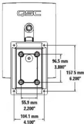
natural_image
Technical line drawing of a cable inserted into a wall-mounted device (no text or symbols)natural_image
Technical line drawing of a device with red cable and connector, showing internal components (no text or symbols)natural_image
Technical line drawing of a mechanical device with no visible text or symbols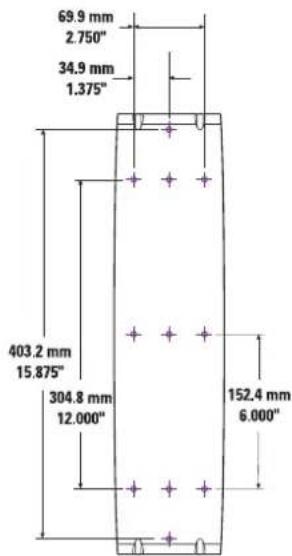

natural_image
Diagram of a screwdriver holding three screws, with a red wire attached to the base (no text or symbols)natural_image
Diagram of a device with internal components and directional arrows indicating rotation (no text or symbols)natural_image
Technical line drawing of a device casing with internal components and red wiring (no text or symbols)natural_image
Line drawing of a portable electronic device with internal components and a separate outlet (no text or symbols)natural_image
Line drawing of a device with a red curved arrow indicating motion, connected to a screwdriver (no text or symbols present)natural_image
Line drawing of a white industrial water heater with a circular top and side outlet (no text or symbols)natural_image
Simple line drawing of a corner joint with a circular detail (no text or symbols)natural_image
Technical line drawing of a mechanical assembly with internal components (no text or symbols)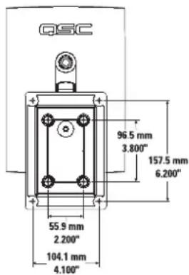
natural_image
Technical line drawing of a cable being inserted into a wall socket (no text or symbols)natural_image
Technical line drawing of a device with red cable and connector, no text or symbols presentnatural_image
Technical line drawing of a screwdriver holding three screws, with a red cable inserted (no text or symbols)natural_image
Technical line drawing of a device with internal components and red wiring (no text or symbols)natural_image
Diagram of a device with internal components and directional arrows indicating rotation (no text or symbols)natural_image
Line drawing of a device casing with internal components and a separate housing (no text or symbols)natural_image
Line drawing of a device with a screwdriver inserted, showing internal components and wiring (no text or symbols)natural_image
Line drawing of a white industrial air purifier unit with a circular vent and side mounting bracket (no text or symbols)natural_image
Technical line drawing of a mechanical device with an arrow indicating a component or assembly (no text or symbols present)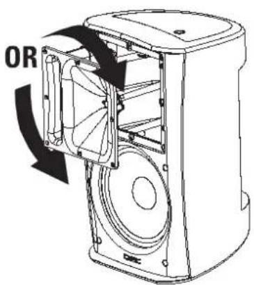
连接
natural_image
Diagram of a cable inserted into a wall-mounted electrical socket with screws (no text or symbols)natural_image
Technical line drawing of a door handle assembly with internal components (no text or symbols)
natural_image
Technical line drawing of a device with red cable and connector, no text or symbols presentnatural_image
Technical line drawing of a screwdriver holding three screws, with a red cable inserted (no text or symbols)natural_image
Line drawing of a device with a rotary knob and red cable, showing internal components without any text or symbols.2- 安全地将扩音器放到套支架上。
natural_image
Technical line drawing of a device casing with internal components and red wiring (no text or symbols)3- 将扬声器线穿过盖板。
4- 选择合适的橡胶密封垫圈,将扬声器
natural_image
Line drawing of a portable water heater with internal components and wiring (no text or symbols)natural_image
Line drawing of a device with cable and screwdriver, no text or symbols presentnatural_image
Line drawing of a white rectangular electronic device with a circular top and side connectors (no text or symbols)How to Contact QSC Audio Products
Mailing address: QSC Audio Products, Inc.
1675 MacArthur Boulevard
Costa Mesa, CA 92626-1468 USA

Telephone Numbers:
Main Number (714) 754-6175
Sales & Marketing (714) 957-7100 or toll free (USA only) (800) 854-4079
Customer Service (714) 957-7150 or toll free (USA only) (800) 772-2834

Facsimile Numbers:
Sales & Marketing FAX (714) 754-6174
Customer Service FAX (714) 754-6173

World Wide Web: www.qscaudio.com
E-mail:info@qscaudio.com
service@qscaudio.com