
KTCV300N - TV receiver KENWOOD - Free user manual and instructions
Find the device manual for free KTCV300N KENWOOD in PDF.

| Brand | Kenwood |
| Model | KTCV300N |
| Product Type | TV Receiver for Vehicle |
| Dimensions (W x H x D) | 188 x 30 x 144 mm |
| Weight (tuner) | 680 g |
| Weight (antenna) | 375 g |
| Operating Voltage | 14.4 V DC (11 V - 16 V) |
| Power Consumption (tuner) | 305 mA |
| Power Consumption (antenna) | 85 mA |
| Color System | NTSC |
| Channel Selection System | PLL Frequency Synthesizer |
| Reception Channels | VHF: 2-13, UHF: 14-69 |
| Demodulation System | Shared Multiplex |
| Antenna Input | 4-Channel Diversity (3.5 mm mini jack) |
| Antenna Output Impedance | 75 Ω (3.5 mm mini jack) |
| Film Antenna Element Size | 345 x 94 mm |
| Operating Temperature | +10 °C to +60 °C |
| Storage Temperature | -30 °C to +85 °C |
| Included Accessories | Film antennas (x2), cables (x2), clamps, cleaner, screws |
| Maintenance | Clean the glass surface with the supplied cleaner before installation |
| Safety | Installation by a professional; do not mount in front of the driver or on an airbag |
Frequently Asked Questions - KTCV300N KENWOOD
User questions about KTCV300N KENWOOD
0 question about this device. Answer the ones you know or ask your own.
Ask a new question about this device
Download the instructions for your TV receiver in PDF format for free! Find your manual KTCV300N - KENWOOD and take your electronic device back in hand. On this page are published all the documents necessary for the use of your device. KTCV300N by KENWOOD.
USER MANUAL KTCV300N KENWOOD
Take the time to read through this instruction manual.
Familiarity with installation and operation procedures will help you obtain the best performance from your new TV Tuner.
For your records
Record the serial number, found on the back of the unit, in the spaces designated on the warranty card, and in the space provided below. Refer to the model and serial numbers whenever you call upon your Kenwood dealer for information or service on the product.
Model KTC-V300N Serial number
US Residence Only
Register Online
Register your Kenwood product at
www.kenwoodusa.com
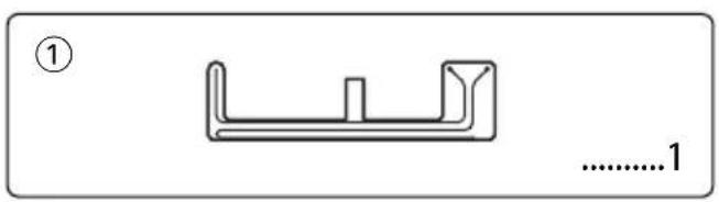
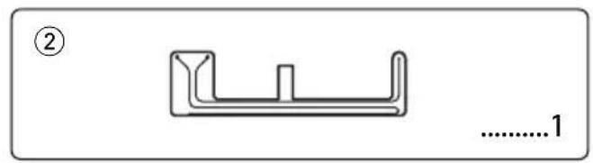
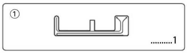
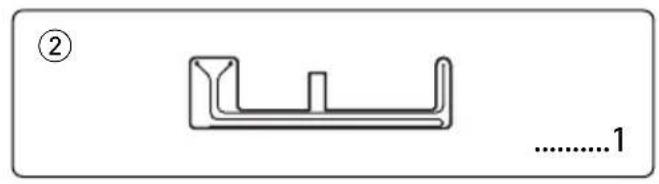
Accessories

Installation the TV Tuner Unit
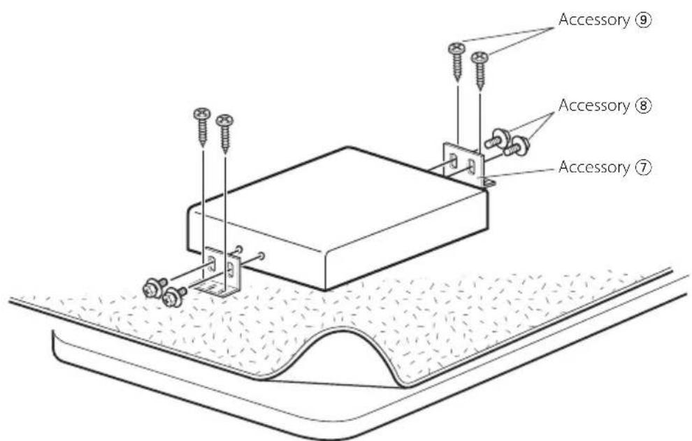
Securing to audio board
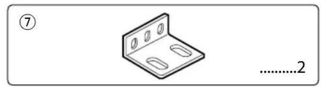
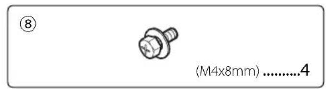
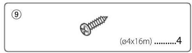
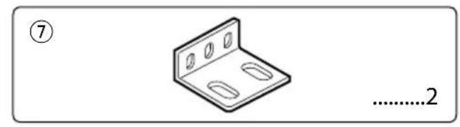
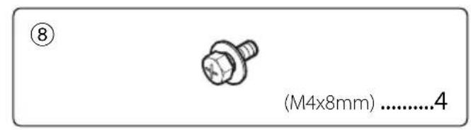
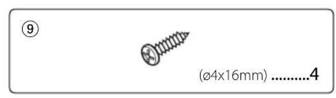
Use screws (Accessory 8 and 9) to fix TV Tuner onto an audio board or another.
Installing the Antenna
Before installing the antenna
WARNING
- Mounting and wiring this product requires skills and experience. For safety's sake, leave the mounting and wiring work to professionals.
CAUTION
- Incar antennas have a lower reception sensitivity than antennas intended for outside mounting. The picture may not appear or may be disturbed if the signal in your area is weak.
- The film antennas are designed specially for use in car.
- Do not attach the film antennas in the following places:
- A place where the driver's view is blocked
- A place where safety parts such as an airbag are prevented from operating normally
- On the surface of a glass such as a rear hatch glass which is frequently moved.
- The reception sensitivity lowers in the following places:
- A place where a heat reflection glass or mirror-type glass film is affixed
- A place where the film antenna of the factory-supplied radio already exists
- On the window where the heating wire already exists
- On the side of the vehicle (door, front quarter window, etc.)
- On the rear window
- On a glass (heat reflecting glass, heat insulating glass, etc.) that blocks radio waves
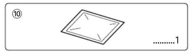
- Using the cleaner (Accessory 10), remove oil and dirt from the glass surface to which the film antennas are to be affixed.
- If the ambient temperature is low, warm the glass before starting the work.
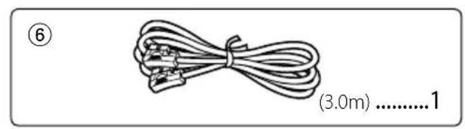
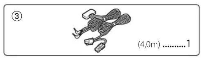
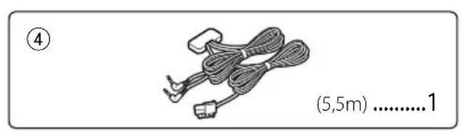
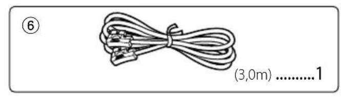
- Before starting the work, confirm well the places where the film antennas (Accessory 1 and 2) and the cables (Accessory 3 and 4) are to be installed. Once peeled off, the film antennas and double-stick tape lose adhesion.
- Do not fold or damage the film antennas.
- Noise generated by the air conditioner or monitor can cause poor TV reception.
- The film antennas cannot be installed depending on the vehicle model.
- The reception sensitivity can vary with the windshield wiper operation depending on the vehicle model.
- The reception sensitivity can vary depending on the relationship between the traveling direction of the vehicle (the pointing direction of the antennas) and the location of the broadcast station.
Installing the Antenna
System connection
- To prevent short circuits, remove the key from the ignition and disconnect the terminal of the battery.
- Make sure to ground the unit to a negative 12V DC power supply.
After the unit is installed, check whether the brake lamps, blinkers, wipers, etc. on the car are working properly. - Thoroughly wipe away oil and other dirt from the installation surface. Please avoid installation on uneven surfaces.
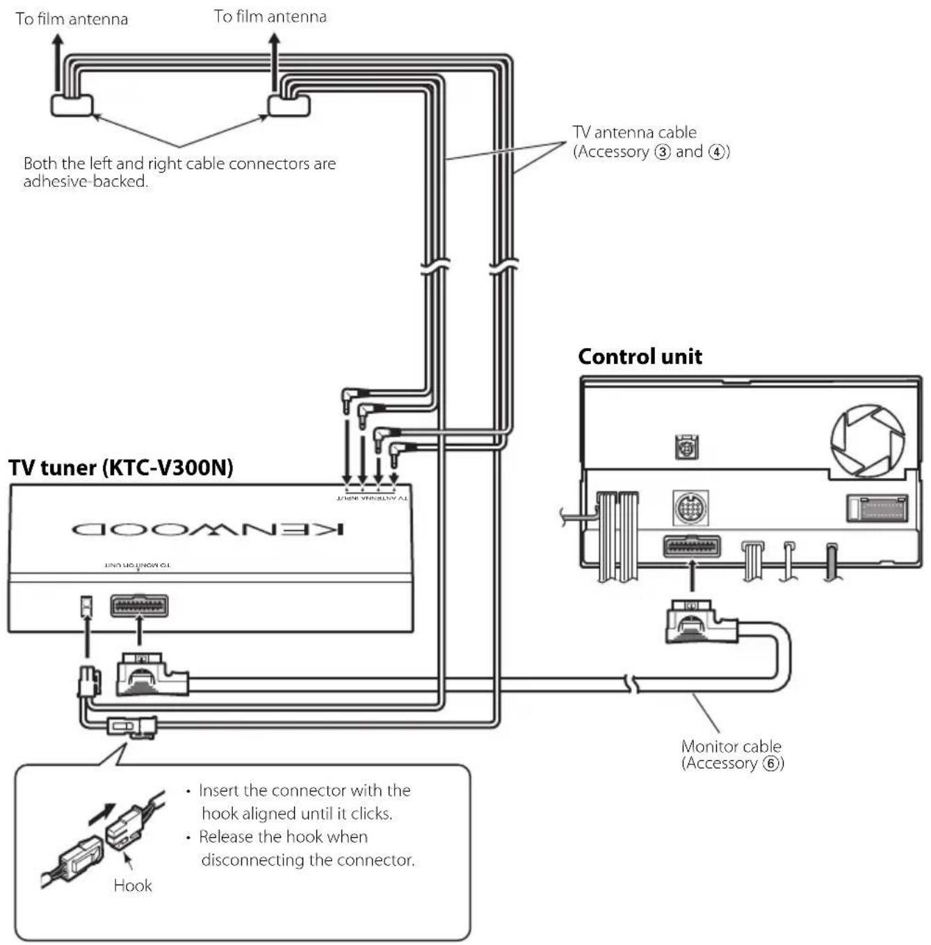
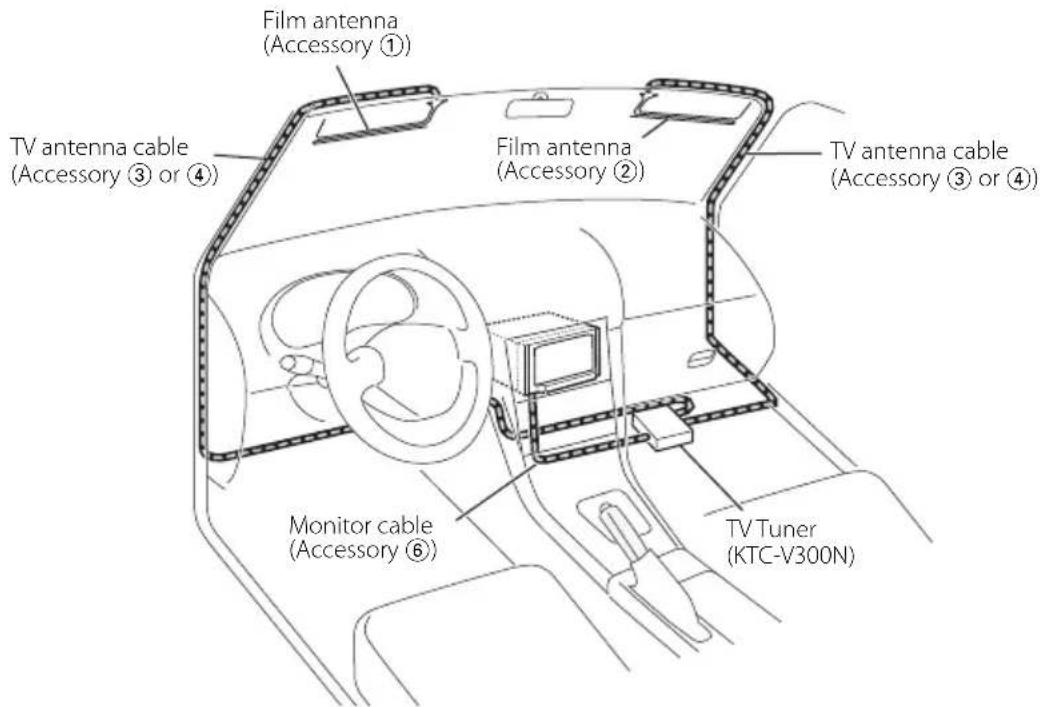
Wiring example
Select either one of the following wiring routes depending on the situation.
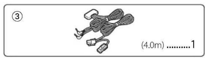
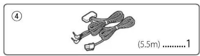
TV antenna cables (Accessory ③ and Accessory ④) are different in length. Use them appropriately to fit the wiring of the vehicle you are working on.
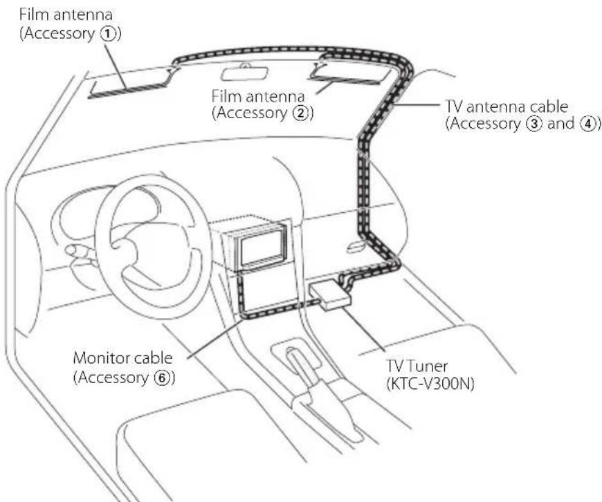
Example A
This example shows a case where the cables are routed on the passenger's seat side. For the right-hand-drive car, route the cables on the left side passenger's seat.
Example B
This example shows a case where it is difficult to route the cables near the rearview mirror.
Installation Procedure
- Confirm the installation place.

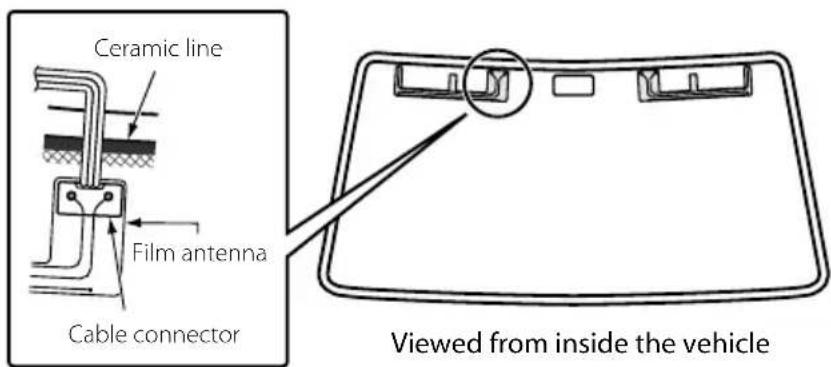
- Affix the film antennas and cable connectors to the front windshield following the laws and regulations of your country.
- Affix each film antenna so that it does not overlap the ceramic line. Affixing the antenna on the ceramic line will lose the adhesion force.
- Using the cleaner (Accessory 10), wipe dirt off the antenna installation surface.
- Affix each film antenna.
1) Peel off the release paper (half-transparent sheet) 1 starting at the slit, and then affix the film antenna to the windshield.

- Once peeled off, the remaining portions of the antenna cannot be affixed again. Confirm the installation place again.
2) Peel off the release paper 2 starting at either slit, and affix the film antenna to the windshield.
3) Peel off the release paper 3 and release paper 4 and affix the film antenna to the windshield in the same manner as above.
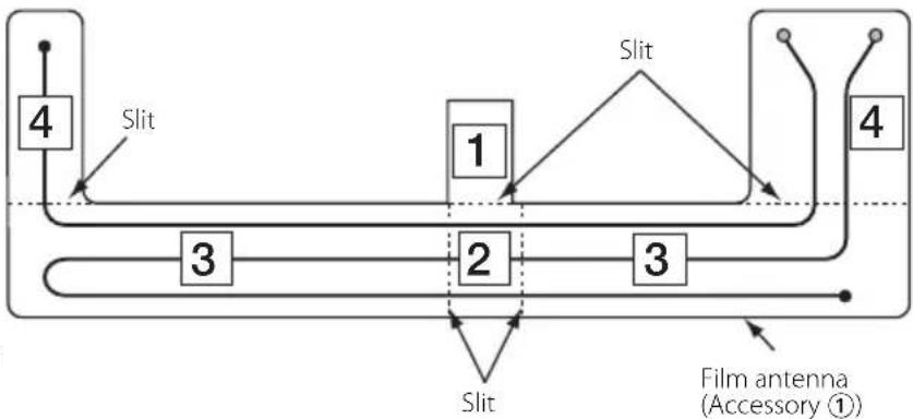

Either the left or right side of the film antenna can be affixed first.
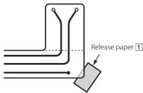
- Inserting the release paper under the corner of the film antenna as shown on the right allows you to peel off other sheets of release paper easily.
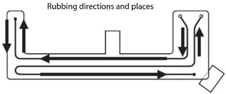
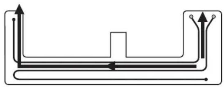
- Rub a rubber spatula against the transparent sheet to affix the antenna element to the windshield tightly. If the rubber spatula is not available, use a small board wrapped with cloth.
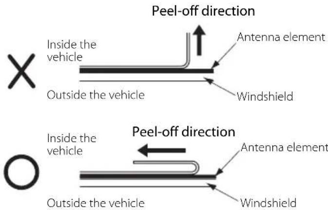
- Slowly peel off the transparent sheet along the element line.
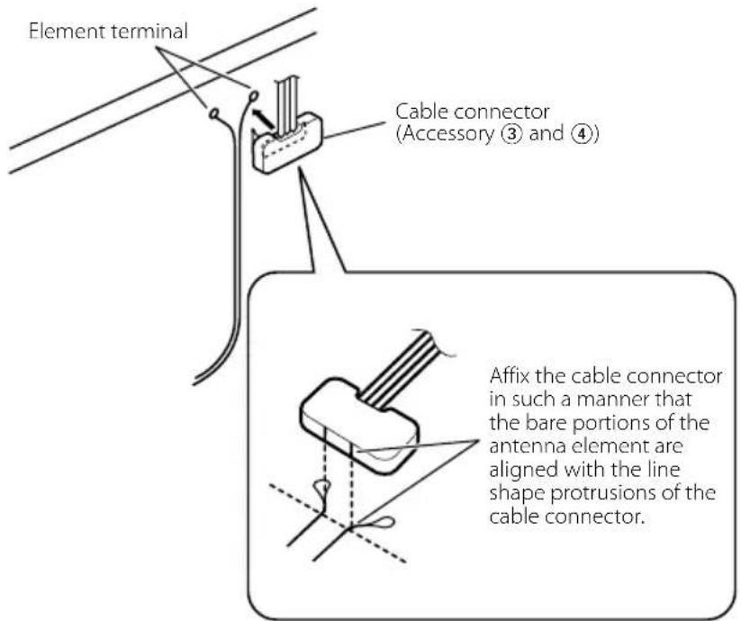
- Make sure that the antenna element has been affixed tightly, and then affix the cable connector to the element terminal.
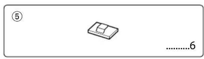
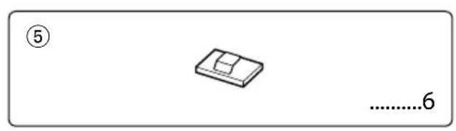
- Route the cable and secure it with the supplied cable clamps (Accessory 5).
Specifications
Specifications subject to change without notice.
TV Tuner section
Colour system :NTSC
Channel selection system :PLL frequency synthesiser system
Television system :M
Channel converge VHF:2-13 ch UHF:14-69 ch
Demodulation system :Split carrier system
Antenna input :4-ch diversity (3.5 0 miniplug)
General
Operating voltage :14.4VDC(11V-16V)
Current consumption :305mA
Dimensions (W× H× D) 188× 30× 144mm 7 - 3 / 8× 1 - 3 / 16× 5 - 11 / 16 inch
Operational temperature range -10ircC + + 60ircC Storage temperature range -30ircC + + 85ircC Weight :680g 1.5 lbs
TV Antenna
Output impedance :75Ω/3.5o minijack
Operating voltage :8VDC
Current consumption :85mA
Cable length :4.0m,5.5 m
Film antenna element si : 345× 94mm 13 - 9 / 16× 3 - 11 / 16 in
Weight :375g 0.8 Ibs
FCC WARNING
This equipment may generate or use radio frequency energy. Changes or modifications to this equipment may cause harmful interference unless the modifications are expressly approved in the instruction manual. The user could lose the authority to operate this equipment if an unauthorized change or modification is made.
NOTE
This equipment has been tested and found to comply with the limits for a Class B digital device, pursuant to Part 15 of the FCC Rules. These limits are designed to provide reasonable protection against harmful interference in a residential installation. This equipment may cause harmful interference to radio communications, if it is not installed and used in accordance with the instructions. However, there is no guarantee that interference will not occur in a particular installation. If this equipment does cause harmful interference to radio or television reception, which can be determined by turning the equipment off and on, the user is encouraged to try to correct the interference by one or more of the following measures:
- Reorient or relocate the receiving antenna.
- Increase the separation between the equipment and receiver.
- Connect the equipment into an outlet on a circuit different from that to which the receiver is connected.
- Consult the dealer or an experienced radio/TV technician for help.
Accessoires
Installation du tuner TV
Sistema de television
:M

- For your records
- Accessories
- Installation the TV Tuner Unit
- Securing to audio board
- Installing the Antenna
- Before installing the antenna
- WARNING
- CAUTION
- System connection
- Wiring example
- Example A
- Example B
- Installation Procedure
- Specifications
- TV Tuner section
- General
- TV Antenna
- FCC WARNING
- NOTE
- Accessoires
- Installation du tuner TV
Brand : KENWOOD
Model : KTCV300N
Category : TV receiver