KVT514 - DVD player KENWOOD - Free user manual and instructions
Find the device manual for free KVT514 KENWOOD in PDF.

| Brand | Kenwood |
| Model | KVT514 |
| Product Type | Car DVD Player |
| Power Supply | 12 V DC (negative ground) |
| Fuse | 15 A |
| Mounting Angle | 30° maximum |
| Cooling Fan | Built-in |
| Input Connectors | AV input (audio/video), rear camera input, USB input |
| Output Connectors | AV output, front pre-outs, rear/subwoofer |
| Features | DVD, CD, MP3 playback, iPod (via adapter), AM/FM radio, steering wheel control (via adapter), illumination dimming |
| Required Wiring | Battery (yellow), ignition (red), ground (black), parking sensor (light green), reverse sensor (violet/white), steering control (light blue/yellow), mute (brown), antenna control (blue), amplifier power (blue/white) |
| Protection | Short circuit protection circuit (displays "PROTECT") |
| Reset | Reset button after installation |
| Compatibility | iPod/iPhone via KCA-iP301V adapter (optional), SIRIUS/XM/HD Radio via adapter (optional), Kenwood navigation system (optional) |
| Installation | Requires professional skills, use included screws, avoid direct exposure to sun, heat, humidity |
Frequently Asked Questions - KVT514 KENWOOD
User questions about KVT514 KENWOOD
0 question about this device. Answer the ones you know or ask your own.
Ask a new question about this device
Download the instructions for your DVD player in PDF format for free! Find your manual KVT514 - KENWOOD and take your electronic device back in hand. On this page are published all the documents necessary for the use of your device. KVT514 by KENWOOD.
USER MANUAL KVT514 KENWOOD
MANUEL D'INSTALLATION
MONITOR CON RECEPTOR DVD
- To prevent a short circuit, remove the key from the ignition and disconnect the battery.
- Make the proper input and output wire connections for each unit.
- Connect the speaker wires of the wiring harness.
- Connect the wiring harness wires in the following order: ground, battery, ignition.
- Connect the wiring harness connector to the unit.
- Install the unit in your car.
- Reconnect the battery.
- Press the reset button.
▲WARNING
- If you connect the ignition wire (red) and the battery wire (yellow) to the car chassis (ground), you may cause a short circuit, that in turn may start a fire. Always connect those wires to the power source running through the fuse box.
▲CAUTION
- Install this unit in the console of your vehicle. Do not touch the metal part of this unit during and shortly after the use of the unit. Metal part such as the heat sink and enclosure become hot.
!
- Mounting and wiring this product requires skills and experience. For safety's sake, leave the mounting and wiring work to professionals.
- Make sure to ground the unit to a negative 12V DC power supply.
- Do not install the unit in a spot exposed to direct sunlight or excessive heat or humidity. Also avoid places with too much dust or the possibility of water splashing.
- Do not use your own screws. Use only the screws provided. If you use the wrong screws, you could damage the unit.
- If the power is not turned ON ("PROTECT" is displayed), the speaker wire may have a short-circuit or touched the chassis of the vehicle and the protection function may have been activated. Therefore, the speaker wire should be checked.
- If your car's ignition does not have an ACC position, connect the ignition wires to a power source that can be turned on and off with the ignition key. If you connect the ignition wire to a power source with a constant voltage supply, as with battery wires, the battery may die.
- If the console has a lid, make sure to install the unit so that the faceplate will not hit the lid when closing and opening.
-
If the fuse blows, first make sure the wires aren't touching to cause a short circuit, then replace the old fuse with one with the same rating.
-
Insulate unconnected wires with vinyl tape or other similar material. To prevent a short circuit, do not remove the caps on the ends of the unconnected wires or the terminals.
- Connect the speaker wires correctly to the terminals to which they correspond. The unit may be damaged or fail to work if you share the wires or ground them to any metal part in the car.
- When only two speakers are being connected to the system, connect the connectors either to both the front output terminals or to both the rear output terminals (do not mix front and rear). For example, if you connect the ④ connector of the left speaker to a front output terminal, do not connect the ⊖ connector to a rear output terminal.
• After the unit is installed, check whether the brake lamps, blinkers, wipers, etc. on the car are working properly. - Mount the unit so that the mounting angle is 30^ or less.
- This unit has the cooling fan (page 5) to decrease the internal temperature. Do not mount the unit in a place where the cooling fan of the unit are blocked. Blocking these openings will inhibit the cooling of the internal temperature and result in malfunction.
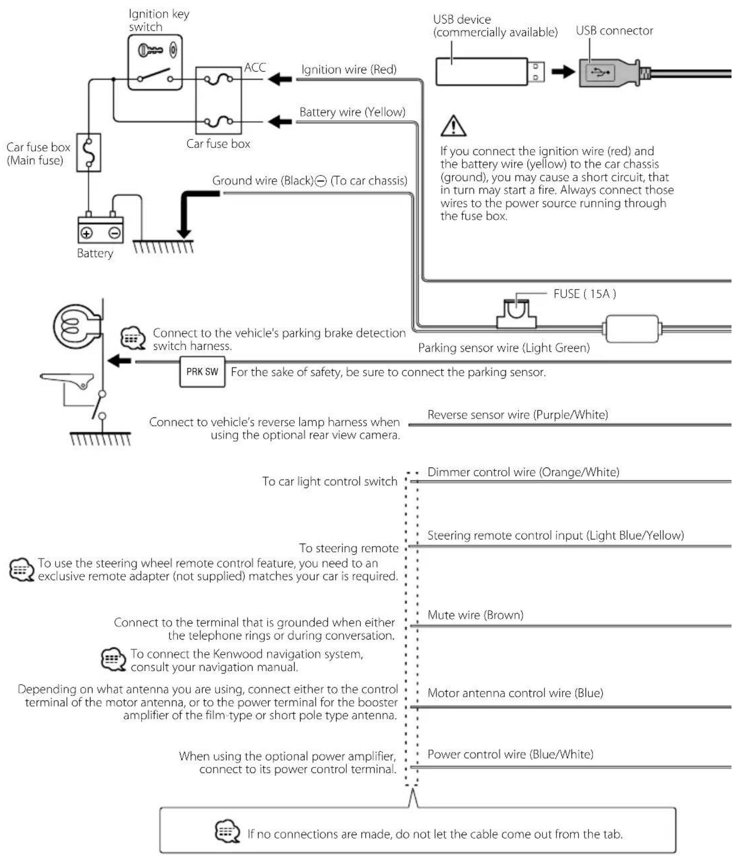
flowchart
graph TD
    A["Car fuse box (Main fuse)"] --> B["Ignition key switch"]
    B --> C["ACC"]
    C --> D["Ignition wire (Red)"]
    C --> E["Battery wire (Yellow)"]
    D --> F["Ground wire (Black)⊖ (To car chassis)"]
    E --> F
    F --> G["PRK SW"]
    G --> H["Connect to vehicle's parking brake detection switch harness."]
    H --> I["Parking sensor wire (Light Green)"]
    I --> J["FUSE (15A)"]
    J --> K["USB device (commercially available)"]
    K --> L["USB connector"]
    M["Switch"] --> N["To car light control switch"]
    O["Sensor"] --> P["To steering remote"]
    Q["Power"] --> R["Mute wire (Brown)"]
    S["Control"] --> T["Motor antenna control wire (Blue)"]
    U["Power Control"] --> V["Power control wire (Blue/White)"]
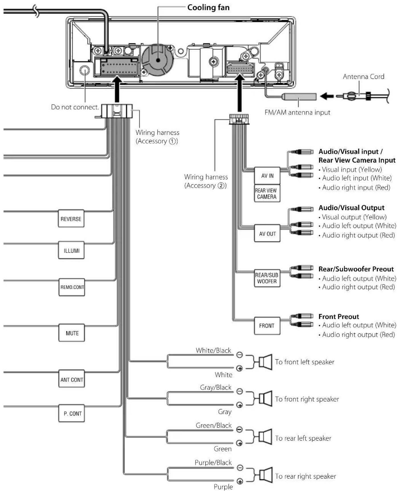
flowchart
graph TD
    A["Cooling fan"] --> B["FM/AM antenna input"]
    B --> C["Antenna Cord"]
    D["Do not connect."] --> E["Wiring harness (Accessory ①)"]
    E --> F["AV IN"]
    F --> G["Audio/Visual input / Rear View Camera Input"]
    F --> H["Audio/Visual Output"]
    E --> I["Wiring harness (Accessory ②)"]
    I --> J["AV OUT"]
    J --> K["Audio Visual output / Rear View Camera Input"]
    J --> L["Audio Left output / White"]
    J --> M["Audio Right output / Red"]
    E --> N["REVERSE"]
    E --> O["ILLUMI"]
    E --> P["REMO.CONT"]
    E --> Q["MUTE"]
    E --> R["ANT CONT"]
    E --> S["P. CONT"]
    T["Front Preout"] --> U["White/Black to front left speaker"]
    T --> V["Gray/Black to front right speaker"]
    T --> W["Green/Black to rear left speaker"]
    T --> X["Purple/Black to rear right speaker"]
    T --> Y["White to rear left speaker"]
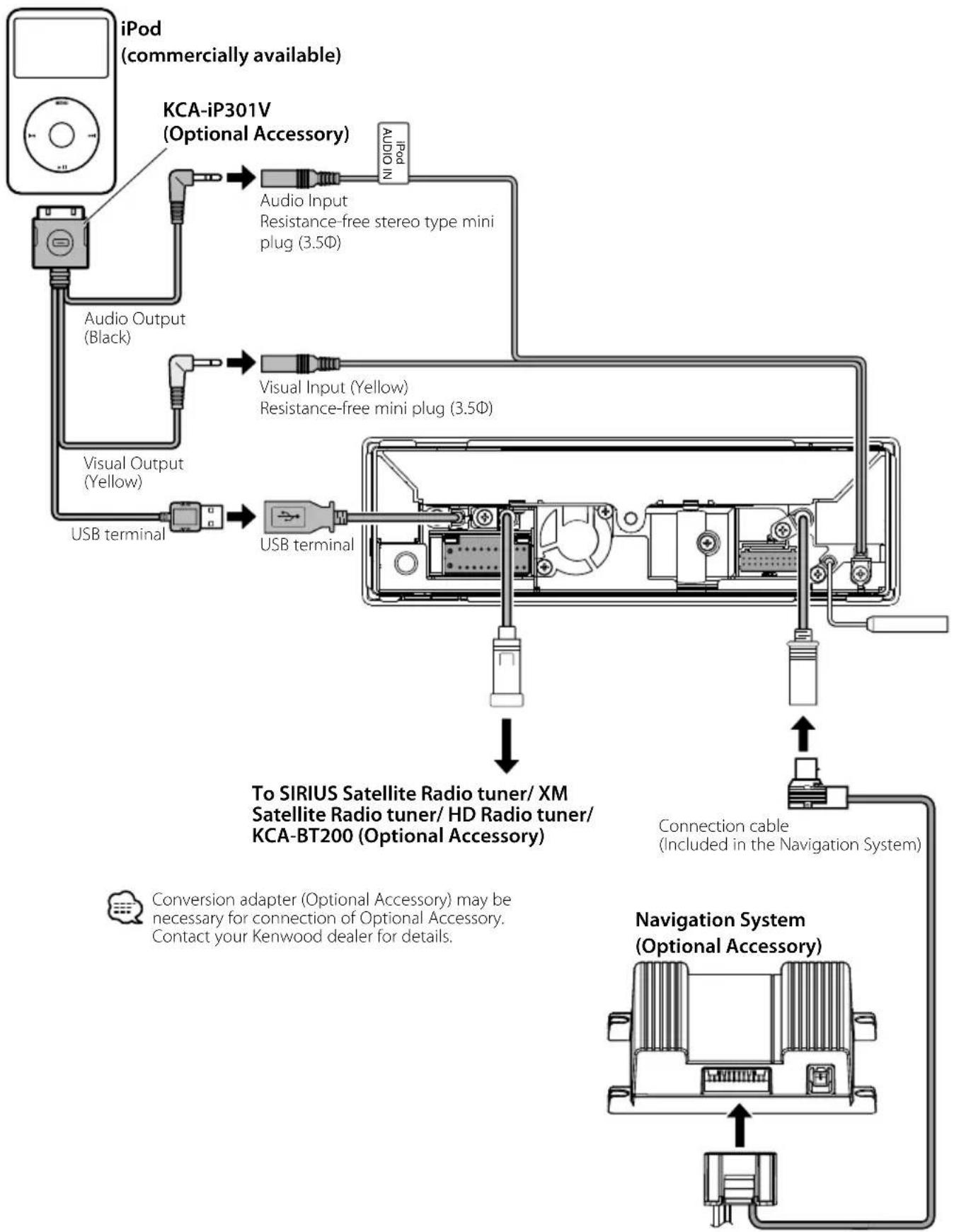
flowchart
graph TD
    A["iPod (commercially available)"] --> B["KCA-iP301V (Optional Accessory)"]
    B --> C["Audio Input Resistance-free stereo type mini plug (3.5Φ)"]
    C --> D["Visual Input (Yellow) Resistance-free mini plug (3.5Φ)"]
    D --> E["USB terminal"]
    E --> F["USB terminal"]
    F --> G["To SIRIUS Satellite Radio tuner/ XM Satellite Radio tuner/ HD Radio tuner/ KCA-BT200 (Optional Accessory)"]
    G --> H["Connection cable (Included in the Navigation System)"]
    H --> I["Navigation System (Optional Accessory)"]
    I --> J["USB terminal"]
    J --> K["Visual Output (Yellow)"]
    K --> L["Audio Output (Black)"]
    L --> M["iPod (commercially available)"]
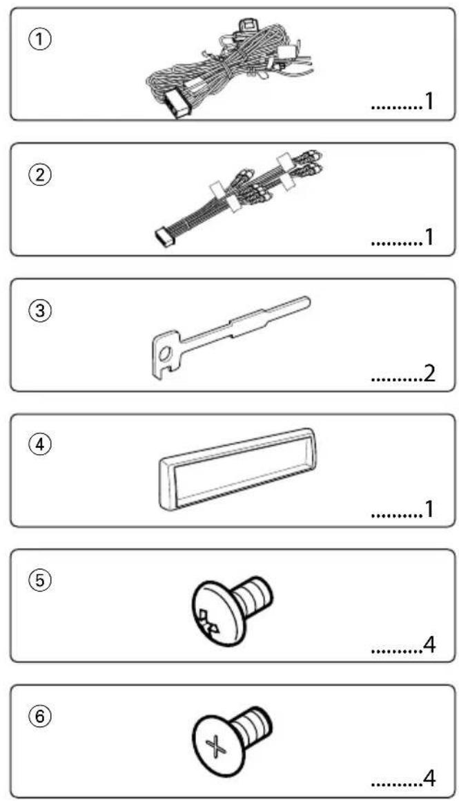
Installation
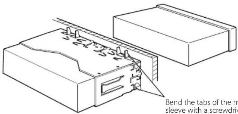
Bend the tabs of the mounting sleeve with a screwdriver or similar utensil and attach it in place.

Make sure that the unit is installed securely in place. If the unit is unstable, it may malfunction (eg, the sound may skip).
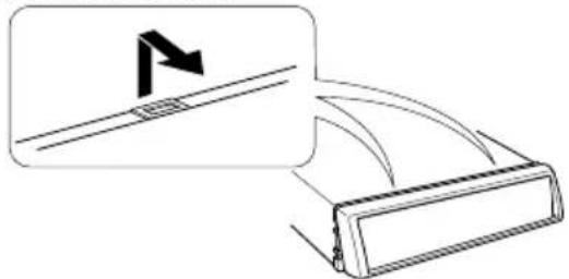
Removing the Hard Rubber Frame (escutcheon)
- Engage the catch pins on the removal tool ③ and remove the two locks on the lower level. Lower the frame and pull it forward as shown in the figure.
Escutcheon (Accessory ④)


- The frame can be removed from the top side in the same manner.
- When the lower level is removed, remove the upper two locations.
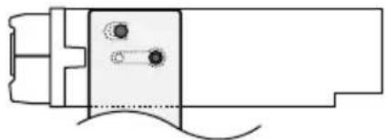
natural_image
Diagram showing a mechanical component with a directional arrow and a close-up inset of its side (no text or symbols)Removing the Unit
- Remove the hard rubber frame by referring to the removal procedure in the section
. - Insert the two removal tools ③ deeply into the slots on each side, as shown.
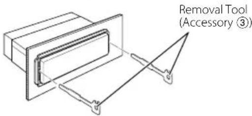
- Lower the removal tool toward the bottom, and pull out the unit halfway while pressing towards the inside.
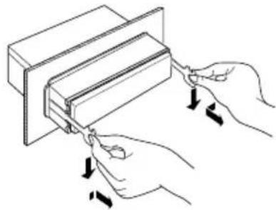
natural_image
Illustration of hands using a tool to adjust or install a rectangular object, with arrows indicating motion (no text or symbols present)
- Be careful to avoid injury from the catch pins on the removal tool.
- Pull the unit all the way out with your hands, being careful not to drop it.
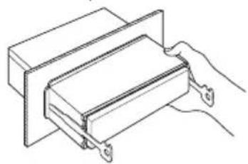
natural_image
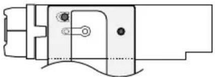
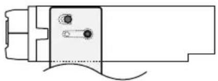
Line drawing of a hand holding a rectangular object with metal brackets (no text or symbols)Installation on Toyota, Nissan or Mitsubishi Car using Brackets at Holes shown by "●"
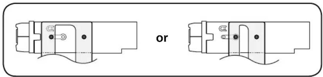
natural_image
Technical line drawing of two mechanical components with no visible text or symbols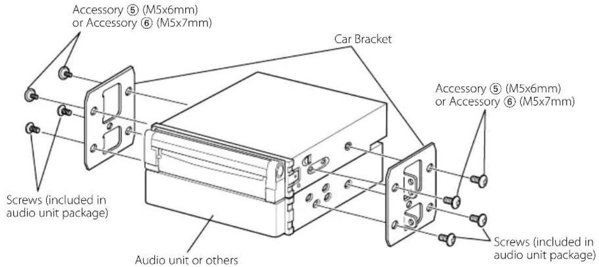

- Do not use your own screws. Use only the screws provided. If you use the wrong screws, you could damage the unit.
Installation on Toyota Car using Brackets at Holes shown by "●"
natural_image
Pure mechanical assembly diagram without any text, numbers, or symbolsor

natural_image
Pure technical line drawing of a mechanical component without any text, numbers, or symbolsWhen using the bracket shown above, you cannot use screws at two holes of the right and left unit sides.
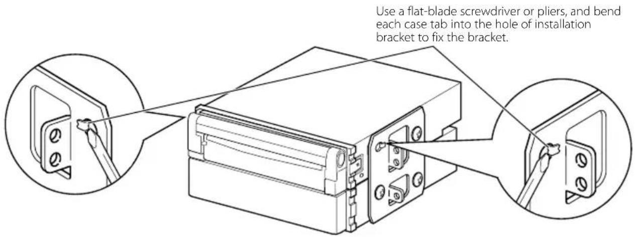
1. Mount the bracket at each side.
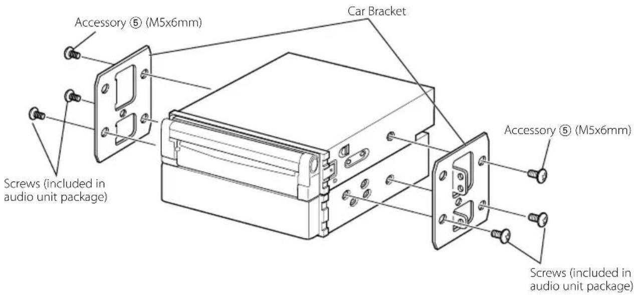
2. Bend each end of case to fix the bracket.
natural_image
Diagram showing a road sign with an arrow pointing right, and a vehicle or device with curved arrows indicating flow or movement (no text or symbols present)natural_image
Illustration of hands using a tool to adjust or install a rectangular component (no text or symbols present)
natural_image
Line drawing of a hand holding a rectangular object with metal brackets (no text or symbols)natural_image
Pure mechanical component diagram without any text, numbers, or symbolsou
natural_image
Pure technical line drawing of a mechanical component without any text, numbers, or symbolsnatural_image
Diagram showing a road sign with an arrow pointing right, alongside a vehicle or device component (no text or symbols present)natural_image
Technical line drawing of a mechanical assembly with no visible text or symbolsnatural_image
Illustration of hands using a tool to adjust or install a rectangular component (no text or symbols visible)
natural_image
Line drawing of a hand holding a rectangular object with metal brackets (no text or symbols)natural_image
Pure mechanical assembly diagram without any text, numbers, or symbols0