PRG486GDH - Cooker THERMADOR - Free user manual and instructions
Find the device manual for free PRG486GDH THERMADOR in PDF.
User questions about PRG486GDH THERMADOR
0 question about this device. Answer the ones you know or ask your own.
Ask a new question about this device
Download the instructions for your Cooker in PDF format for free! Find your manual PRG486GDH - THERMADOR and take your electronic device back in hand. On this page are published all the documents necessary for the use of your device. PRG486GDH by THERMADOR.
USER MANUAL PRG486GDH THERMADOR
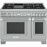
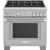
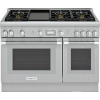
PRO-HARMONY™ Gas Ranges
MANUEL D'INSTALLATION
Professional® PRO-HARMONY™
Models/
Modèles /
Modelos:
PRG30
PRG36
PRG48
PRL30
PRL36
PRL48
Table of Contents
Safety Instructions 1
Important Installation Information 2
Step 1: Ventilation Requirements 3
Step 2: Cabinet Preparation 4
Step 3: Unpacking and Moving the Range . . . . 8
Step 4: Installing Anti-Tip Device 9
Step 5: Gas Requirements and Hookup . . . . . . 11
Step 6: Electrical Requirements, Connection & Grounding 13
Step 7: Backguard Installation 14
Step 8: Door Removal and Reinstallation . . . 15
Step 9: Placing and Leveling the Range .16
Step 10:Burner Test and Adjustment 18
Installer Checklist 19
To Clean and Protect Exterior Surfaces 19
This Thermador Appliance is made by
BSH Home Appliances Corporation
5551 McFadden Ave.
Huntington Beach, CA 92649
Questions?
1-800-735-4328
www.thermador.com
We look forward to hearing from you!
Safety Instructions

Important Safety Instructions
PLEASE READ ENTIRE INSTRUCTIONS BEFORE PROCEEDING
APPROVED FOR ALL RESIDENTIAL APPLIANCES
IMPORTANT: Save these Instructions for the Local Gas Inspector's use.
INSTALLER: Please leave these Instructions with this unit for the owner.
OWNER: Please retain these instructions for future reference.

WARNING:
Disconnect power before installing. Before turning power ON, be sure that all controls are in the OFF position.
Important:
Local codes vary. Installation, gas connections and grounding must comply with all applicable codes.
WARNING:
If the information in this manual is not followed exactly, a fire or explosion may result causing property damage, personal injury or death.
-- Do not store or use combustible materials, gasoline or other flammable vapors and liquids in the vicinity of this or any other appliance.
-- WHAT TO DO IF YOU SMELL GAS
- Do not try to light any appliance.
- Do not touch any electrical switch.
- Do not use any phone in your building.
- Immediately call your gas supplier from a neighbor's phone. Follow the gas supplier's instructions.
- If you cannot reach your gas supplier, call the fire department.
-- Installation and service must be performed by a qualified installer, authorized service agency or the gas supplier.
For Massachusetts Installations:
- Installation must be performed by a qualified or licensed contractor, plumber or gas fitter qualified or licensed by the state, province or region where this appliance is being installed.
- Shut-off valve must be a "T" handle gas cock.
- Flexible gas connector must not be longer than 36 inches.

WARNING:

- All Ranges can tip.
- Injury to Persons could result.
- Install Anti-Tip Device packaged with range.
- See Installation Instructions.
TO REDUCE THE RISK OF TIPPING OF THE APPLIANCE, IT MUST BE SECURED BY A PROPERLY INSTALLED ANTI-TIP DEVICE. VERIFY THAT THE ANTI-TIP DEVICE IS ENGAGED PER INSTALLATION INSTRUCTIONS. (NOTE: ANTI-TIP DEVICE IS REQUIRED ON ALL 30" AND 36" RANGES; 48" RANGES DO NOT REQUIRE AN ANTI-TIP DEVICE:)
Note:
This Range is NOT designed for installation in manufactured (mobile) homes or for installation in Recreational Park Trailers.
Do Not install this range outdoors.
GAS Type Verification
Verify the type of gas supplied to the location. Ensure that the appliance is connected to the type of gas for which it is certified. Ranges are certified for use with only natural gas or propane (LP) gas. Make certain the range matches the gas type available; these ranges are NOT convertible between gas types.
Important Installation Information

WARNING:
To avoid possible burn or fire hazard, a backguard designed specifically for this range must be installed whenever the range is used.
Refer to the "Chart C: Backguard Kit Model Numbers" on page 14, for the correct backguard models that are designed for this range. After selecting the correct backguard, the range must be installed properly, using the minimum clearances to combustible surfaces specified in the Cabinet Preparation instructions on page 4.
Important:
- A backguard must be utilized when there is less than a 12" horizontal clearance between combustible materials and the back edge of the range. A Thermador backguard must be ordered separately and installed at the rear of the range. A Low Back is supplied with the 30" model, and all other models are supplied with a Flush Island Trim. For island installations and other installations with more than 12" clearance, an optional stainless steel Island Trim is available to cover the backguard mounting flanges.
- Verify that the appliance is correct for the type of gas being provided. Refer to Step 5 on page 11 before proceeding with the installation.

CAUTION:
To eliminate risk of burns or fire caused by reaching over heated surface units, cabinet storage located above the surface units should be avoided.
Gas Supply:
Natural Gas 6 inch water column. (14.9 mb) min., 14 inch (34.9 mb) maximum
Propane Gas — 11 inch water column. (27.4 mb) min., 14 inch (34.9 mb) maximum
Electric Power Supply:
30" Model:
4 Burners — 120 VAC, 60 Hz., 1Ph., 10 Amp circuit.
36"Models:
6 Burners — 120 VAC, 60 Hz., 1Ph., 10 Amp circuit
4 Burners with Griddle — 120 VAC, 60 Hz., 1Ph., 20 Amp circuit.
48" Models:
6 Burners with Griddle — 120 VAC, 60 Hz., 1Ph., 20 Amp circuit.

CAUTION:
When connecting the unit to propane gas, make certain the propane gas tank is equipped with its own high-pressure regulator in addition to the pressure regulator supplied with the range. The maximum gas pressure to this appliance must not exceed 14.0 inches water column (34.9 mb) from the propane gas tank to the pressure regulator.

CAUTION:
This unit is designed as a cooking appliance. Based on safety considerations, never use it for warming or heating a room.
This appliance has been tested in accordance with ANSI Z21.1, Standard for Household Cooking Appliances (USA) and in accordance with CAN 1.1-M81 Domestic Gas Ranges (Canadian). It is strongly recommended that this appliance be installed in conjunction with a suitable overhead vent hood. (See Step 1 for Ventilation Requirements.) Due to the high heat capability of this unit, particular attention should be paid to the hood and duct work installation to assure it meets local building codes.
This appliance complies with one or more of the following standards:
- UL 858, Standard for the Safety of Household Electric Ranges
- UL 923, Standard for the Safety of Microwave Cooking Appliances
- UL 507, Standard for the Safety of Electric Fans
ANSI Z21.1, American National Standard for Household Cooking Gas Appliances
CAN/CSA-C22.2 No. 113-08 Fans and Ventilators
CAN/CSA-C22.2 No. 61-08 Household Cooking Ranges
Check local building codes for the proper method of appliance installation. Local codes vary. Installation, electrical connections and grounding must comply with all applicable codes. In the absence of local codes the appliance should be installed in accordance with the National Fuel Gas Code ANSI Z223.1/ NFPA 54 current issue and National Electrical Code ANSI/NFPA 70 -current issue. In Canada, installation must be in accordance with the CAN 1-B149.1 and .2 - Installation Codes for Gas Burning Appliances and/or local codes.
It is the responsibility of the owner and the installer to determine if additional requirements and/or standards apply to specific installations.
Step 1: Ventilation Requirements
It is strongly recommended that a suitable exhaust hood be installed above the range. Downdraft ventilation should not be used. The following table indicates the ventilation hood options and blower capacity guidelines that are recommended for use with all Thermador ranges.
1. Select Hood and Blower Models:
- For wall installations, the hood width must, at a minimum, equal the width of the range. Where space permits, a hood larger in width than the range may be desirable for improved ventilation performance.
- For island installations, the hood width should, at a minimum, overhang the range by 3^ on each side.
Important:
Ventilation hoods and blowers are designed for use with single wall ducting. However, some local building codes or inspectors may require double wall ducting. Consult local building codes and/or local agencies, before starting, to assure that hood and duct installation will meet local requirements.
Do not install a microwave oven/ventilator combination above the range, as these type of units do not provide the proper ventilation and are not suitable for use with the range.
2. Hood Placement:
- For best smoke elimination, the lower edge of the hood should be installed 30^ above the range cooking surface. (See Figure 1).
NOTICE:
Most range hoods contain combustible components which must be considered when planning the installation.
- If the hood contains any combustible materials (i.e. a wood covering), it must be installed a minimum of 40^ above the cooking surface.
3. Consider Make-Up Air:
- Due to the high volume of ventilation air, a source of outside replacement air is recommended. This is particularly important for tightly sealed and insulated homes.
- A qualified heating and ventilating contractor should be consulted.
| Range Width | Range Top Configuration Ventilation Options | |
| 30" 4 burners | 30" or 36" Pro Wall Hood 30" or 36" Custom Insert w/ optional blower 42" Island Hood w/ optional blower | |
| 36" | 4 burners with griddle | 36" or 42" Pro Wall Hood 36" Custom Insert w/ optional blower 42" or 48" Island Hood w/ optional blower |
| 6 burners | ||
| 48" 6 burners with griddle | 48" or 54" Pro Wall Hood 48" Custom Insert w/ optional blower | |
Important Notes:
It is recommended that a Thermador Professional wall or island hood or custom insert is used with Thermador Professional Ranges.
The HPWB or PH Professional Series Wall Hoods or the Professional Series Custom Inserts are recommended ventilation solutions for these ranges.
Refer to www.Thermador.com for a complete selection of Professional Ventilation options, Blowers, and Accessories.
- For high output gas ranges (60,000 BTU or greater), the minimum of one (1) CFM of ventilation per 100 BTU is recommended. If the range has a griddle, add 200 CFM to the estimated blower capacity. Additional blower capacity may be required for longer duct runs.
For island applications, it is recommended to use a hood width that exceeds the width of the range by 6" (overlapping the range by a minimum of 3" on each end).
CFM = "cubic feet per minute" (standard blower capacity rating).
Step 2: Cabinet Preparation
- The range is a free standing unit. If the unit is to be placed adjacent to cabinets, the clearances shown in Figure 1 are required. The same clearances apply to island installations, except for the overhead cabinets, which must have a space wide enough to accept the flared island hood, as indicated in Figure 1.
- These ranges may be recessed into the cabinets beyond the edge of the front face of the oven (See Figure 2).

CAUTION:
In these installations, the door and cabinet can cause a pinching hazard.
- The gas and electrical supply should be within the zone shown in Figure 3a.
Note:
The maximum depth of over head cabinets installed on either side of the hood is 13^ (330 mm).
A 40-inch minimum clearance is required between the top of the cooking surface and the bottom of an unprotected cabinet. A 30-inch clearance can be used when the bottom of the wood or metal cabinet is protected by not less than 1/4 inch of a flame retardant material covered with not less than No. 28 MSG sheet steel, 0.015 inch (0.4 mm) thick stainless steel, 0.024 inch (0.6 mm) aluminum, or 0.020 inch (0.5 mm) thick copper. Flame retardant materials bear the mark:
UNDERWRITERS LABORATORIES INC. CLASSIFIED MINERAL AND FIBER BOARDS SURFACE BURNING CHARACTERISTICS
Followed by the flame spread and smoke ratings. These designations are shown as "FHC (Flame Spread/Smoke Developed)". Materials with "O" flame spread ratings are flame retardant. Local codes may allow other flame spread ratings.
- Any openings in the wall behind the range and in the floor under the range must be sealed.
- When there is less than a 12" horizontal clearance between combustible material and the back edge of the range above the cooking surface, a Thermador Low Back or Pot and Pan Shelf must be installed. (See Figure 2). When clearance to combustible material is over 12", a Thermador Flush Island Trim may be used. Figure 2 indicates the space required for each type of guard.
-
Always keep appliance area clear and free from combustible materials, gasoline and other flammable vapors and liquids.
-
Do not obstruct the flow of combustion and ventilation air to the unit.
- A 5 inch minimum clearance is needed when the range is installed beside a combustible side wall.
As defined in the "National Fuel Gas Code" (ANSI Z223.1, NFPA 54 Current Edition).
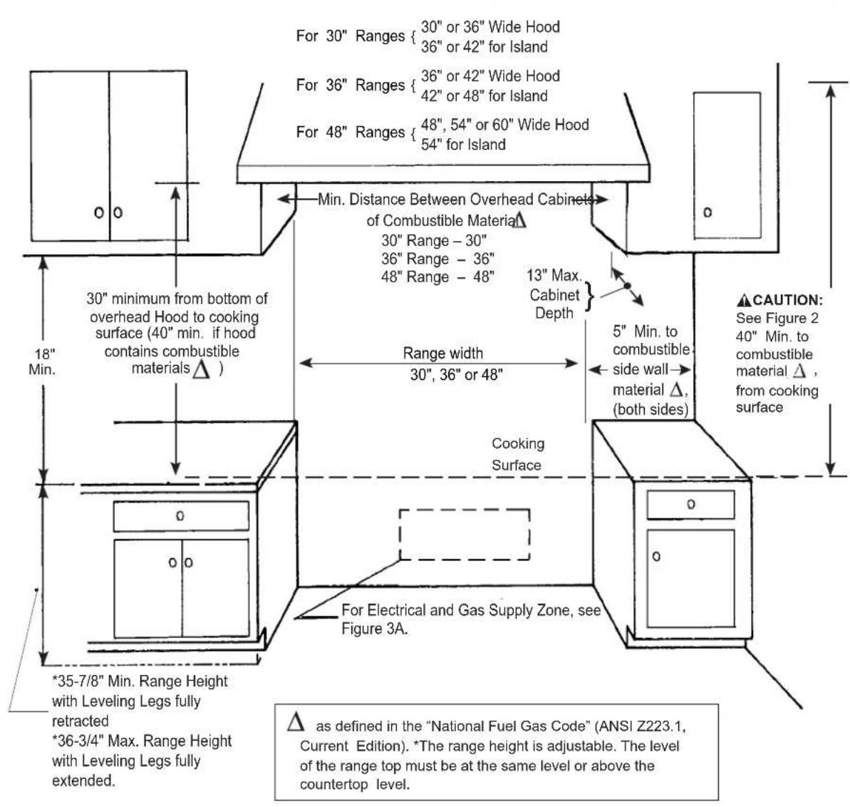
Figure 1: Cabinet Clearances
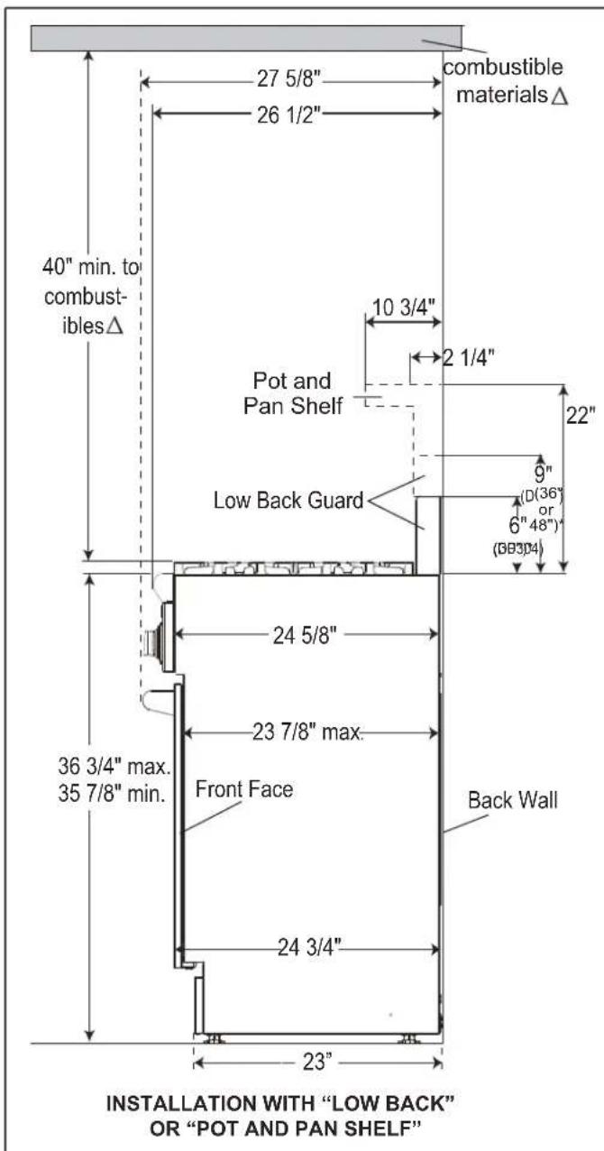
Figure 2: Side View
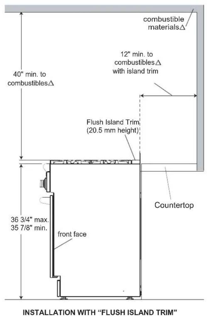
As defined in the "National Fuel Gas Code" (ANSI Z223.1, Current Edition).
- Refers to 30", 36" and 48" range models.
Note:
With the oven door fully open, the top of the door extends to 44-7/8" from the back wall, behind the range when installed. Installation must allow ample clearance for movement around the door when fully open.
Gas and Electric Supply
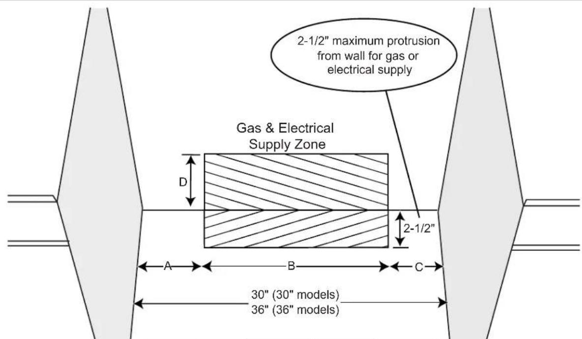
| Model | A | B | C | D |
| 30" | 5-3/4" | 18-7/16" | 5-13/16" | 2-15/16" |
| 36" | 8-1/16" | 19-13/16" | 8-1/8" | 3-3/16" |
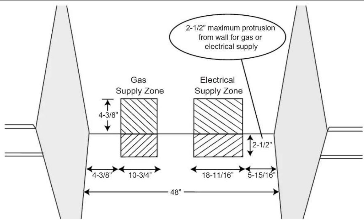
Figure 3a: Gas & Electrical Supply Locations for 30" and 36" Gas Ranges
Figure 3b: Gas & Electrical Supply Locations for 48^ Gas Ranges
Note:
If not already present, install gas shut-off valve in an easily accessible location. Make sure all users know where and how to shut off the gas supply to the range.
Note:
The installer should inform the consumer of the location of the gas shut-off valve.
Note:
Any opening in the wall behind the appliance and any opening in the floor under the appliance must be sealed.
The gas ranges may be connected to the power supply with the range supply cord supplied with the range or by hard-wiring to the power supply. It is the responsibility of the installer to provide the proper wiring components (cord or conduit and wires) and complete the gas connection as dictated by local codes and ordinances, and/or the National Electric Code. The units must be properly grounded. Refer to Step 6 for details.
The range must be connected only to the type of gas for which it is certified. If the range is to be connected to propane gas, ensure that the propane gas supply tank is equipped with its own high pressure regulator in addition to the pressure regulator supplied with the range. (See Step 5.)
Note:
The range is designed for flush installation to the back wall. For a successful installation, it may be necessary to reposition the gas-supply line and electrical cord as the range is pushed back to its final position.
SUGGESTION: This may be accomplished by carefully pulling on a rope or twine looped around the gas or electrical supply line as the range is pushed back into its final installed position.
Important:
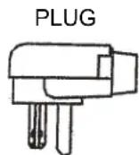
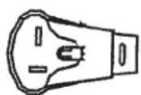
The cord supplied with the gas ranges, having an electric griddle, requires a NEMA 5-20 receptacle, shown here. Local codes may require a different wiring method.

NEMA 5-20 RECEPTACLE
Electrical Supply
Installation of the range must be planned so that the rough-in of the junction box for the receptacle will allow maximum clearance to the rear of the unit. To minimize binding when the unit is connected to the receptacle or junction box, orient the receptacle and slide back into position.
When the power supply cord is connected to the mating receptacle, the combined plug/receptacle connection should protrude no more than 2-1/2" from the rear wall. See Figure 3b.
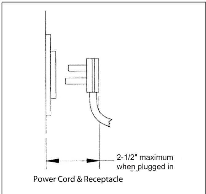
Figure 4: Wall Connection
Step 3: Unpacking and Moving the Range

CAUTION
Proper equipment and adequate manpower must be used in moving the range to avoid injury, and to avoid damage to the unit or the floor. The unit is heavy and should be handled accordingly.
-
The range has an approximate shipping weight as shown in Chart A. The literature packet with manuals, cooking grates, griddle plate, burner caps, front kick panel and oven racks must be removed to facilitate handling. Removing the door(s) is also recommended (See "Step 8: Door Removal and Reinstallation" on page 15). This will reduce the weight as shown in Chart A. See Figure 2 on page 6. Do not remove the griddle element and tray assembly.
-
Remove the outer carton and packing material from the shipping pallet. The all gas ranges are held to the pallet by four (4) bolts (see Figure 5). The two front pallet bolts are accessible only after removing the Kick Panel. Remove the two screws below the lower corners of the oven cavity and lift the Kick Panel away from the two projections on the range's cast base that capture the bottom edge of the Panel. After removing the bolts, the range must be lifted and removed from the pallet.

CAUTION:
DO NOT lift the range by the oven door's handle, as this may damage the door hinges and cause the door to fit incorrectly to the oven cavity.
| Chart A | 30" Range | 36" Range | 48" Range |
| Shipping Weight 300 lbs. | 335 lbs. | 534 lbs. | |
| Weight without packing materials | 265 lbs. | 300 lbs. | 469 lbs. |
| Without door(s), burner caps, front kick panel and oven racks | 142 lbs. | 207 lbs. | 322 lbs. |

Figure 5: Removal of the Four (4) Shipping Bolts
Note:
Leave adhesive-backed foam layer over brushed-metal surfaces, to protect finish from scratches, until the range is installed in its final position.
- Due to the weight, a dolly with soft wheels should be used to move this unit. The weight must be supported uniformly across the bottom (See Figure 6).
- After transporting the range by dolly close to its final location, the range can be tipped back and supported on the rear legs while the dolly is carefully removed. THE FLOOR UNDER THE LEGS SHOULD BE PROTECTED BEFORE PUSHING THE UNIT INTO POSITION. The anti-tip device must be installed (STEP 4), gas and electrical connections should be made (STEPS 5 and 6), and the guard installed (STEP 7) before the range is placed in its final position.
- Do not install the oven door(s) until the range is in its final location.
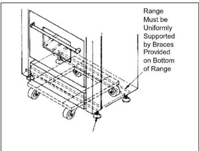
Figure 6: Dolly Positioning
Remove all tape and packaging before using the appliance.
Destroy the packaging after unpacking the appliance.
Never allow children to play with packaging material.
Step 4: Installing Anti-Tip Device
For all 30" and 36" ranges, an anti-tip device must be installed per these instructions.

WARNING - RANGE TIPPING HAZARD
- All ranges can tip and injury can result. To prevent accidental tipping of the range, attach it to the floor, wall or cabinet by installing the Anti-Tip Device supplied.
- A risk of tip-over may exist if the appliance is not installed in accordance with these instructions.
- If the range is pulled away from the wall for cleaning, service or any other reason, ensure that the Anti-Tip Device is properly
reengaged when the range is pushed back against the wall. In the event of abnormal usage (such as a person standing, sitting, or leaning on an open door), failure to take this precaution can result in tipping of the range. Personal injury might result from spilled hot liquids or from the range itself.

WARNING - ELECTRICAL SHOCK HAZARD
- Use extreme caution when drilling holes into the wall or floor. There may be concealed electrical wires located behind the wall or under the floor.
- Identify the electrical circuits that could be affected by the installation of the Anti-Tip Device, then turn off power to these circuits.
- Failure to follow these instructions may result in electrical shock or other personal injury.

WARNING:
- All Ranges can tip.
- Injury to Persons could result.
- Install Anti-Tip Device packaged with range.
- Verify that the anti-tip device is engaged.
- See Installation Instructions.
ATTENTION - PROPERTY DAMAGE
- Contact a qualified installer or contractor to determine the proper method for drilling holes through the wall or floor material (such as ceramic tile, hardwood, etc.)
- Do not slide the range across an unprotected floor.
- Failure to follow these instructions may result in damage to wall or floor coverings.
Tools Needed for Installation of Anti-Tip Device:
- Screwdriver, Phillips
- Drill, electric or hand
- Measuring tape or ruler
-
1/8" drill bit (wood or metal wall or floor)
-
3/16" carbide-tipped masonry drill bit (concrete or concrete block wall or floor)
-
3/16" anchors, drywall or concrete, 4 each (not required if mounting bracket is being attached to solid wood or metal)
-
Hammer
- Pencil or other marker
30" and 36" Ranges
See Figure 7 and Figure 8.
| Thermador Service Part No. | Qty Description | |
| 415078 4 | Screw, Phillips, #10 x 1-1/2" | |
| 647936 1 | Anti-Tip Bracket, Floor-Mounted |
Important Installation Information:
- The anti-tip bracket may be attached to a solid wood cabinet having a minimum wall thickness of 3/4" .
- The thickness of the wall or floor may require use of longer screws, available at your local hardware store.
- In all cases, at least two (2) of the bracket mounting screws must be fastened to solid wood or metal.
- Use appropriate anchors when fastening the mounting bracket to any material other than hard-wood or metal.
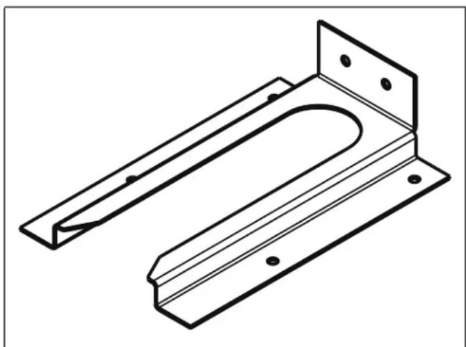
Figure 7: Anti-tip Bracket
Note:
48" Ranges do not require the Anti-Tip Bracket. This is due to the size and weight distribution of the 48" models.
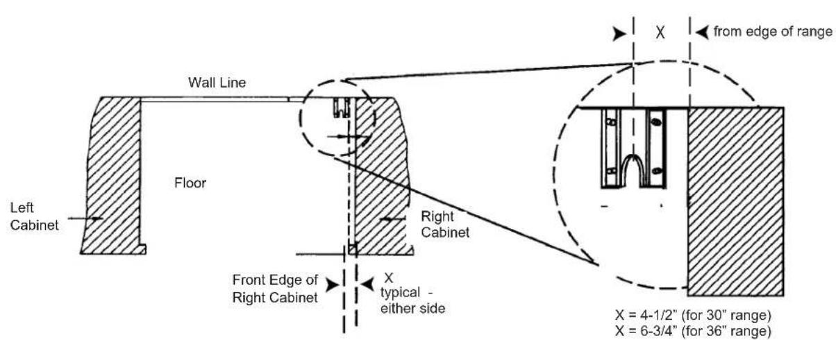
Figure 8: Placement of Anti-Tip Bracket (Top View)
- Prepare holes at fastener locations as identified below:
- For walls, wall studs, or floors composed of solid wood or metal, drill 1/8" pilot holes.
- For walls or floors composed of drywall, sheet-rock or other soft materials, drill 3/16" holes to a minimum depth of 1 - 3 / 4" , then tap plastic anchors into each of the holes using a hammer.
- For walls or floors composed of concrete or concrete block, drill 3/16" holes to a minimum depth of 1-3/4", then tap concrete anchors into each of the holes using a hammer.
- For walls or floors having ceramic tile covering, drill 3/16" holes through the tile only, then drill into the material behind the tile as indicated immediately above.
- If the range is moved to a new location, the Anti-Tip Device must be removed and reinstalled.
Mounting Anti-Tip Bracket
The alternative floor mounted bracket shall be installed as follows:
- Place bracket on floor in position shown in Figure 8 (Bracket may be used in either corner of the installation area).
- Secure to floor or wall stud.
- Later, when the unit is installed, the adjustable leg will slide under the bracket.
Step 5: Gas Requirements and Hookup
Verify the type of gas being used at the installation site. As shipped from the factory, units are configured for use with only natural gas or propane (LP) gas. Make certain the range matches the type of gas available at this location. These ranges are NOT convertible between different types of gas.
For installation of the appliance at high altitude, please consult your local gas company for their recommendation of the correct orifice sizes and any other necessary adjustments that will provide proper gas combustion at specified altitudes.

CAUTION
When connecting unit to propane gas, make certain the propane gas tank is equipped with its own high pressure regulator in addition to the pressure regulator supplied with the appliance. The pressure of the gas supplied to the appliance regulator must not exceed 14" (34.9 mb) water column.
Natural Gas Requirements:
Inlet Connection: 1/2" NPT internal
(Minimum 3/4" dia. flex line.)
Supply Pressure: 6" min. to 14" max. water column.
(14.9 to 34.9 mb)
Manifold Pressure: 5" water column (12.5 mb)
Propane Gas Requirements:
Inlet Connection: 1 / 2^ NPT internal
(Minimum 3/4 dia. flex line.)
Supply Pressure: 11" min. to 14"max. water column.
(27.4 mb to 34.9 mb)
Manifold Pressure: 10" water column (24.9 mb)

WARNING
Gas line must not come in contact with any components inside back cover of range.
Hook Up
- A manual gas shut-off valve must be installed external to the appliance, in a location accessible from the front, for the purpose of shutting off the gas supply. The supply line must not interfere with the back of the unit. Make sure the gas supply is turned off at the manual shut-off valve before connecting the appliance.
- The range is supplied with its own pressure regulator that has been permanently mounted within the range body.
- Use 3/4" flex line to connect between the gas supply and the appliance gas inlet, located at the lower right portion of the range. (See Figure 9.) The appliance inlet pipe connection is 1 / 2'' NPT. Use caution to avoid crimping the 3/4" flex line when making bends. Suggested length of flex line is 48'' , however, please check local codes for your area's requirements before installation.
- The gas supply connections shall be made by a competent technician and in accordance with local codes or ordinances. In the absence of local codes, the installation must conform to the National Fuel Gas Code ANSI Z223.1/NFPA54-current issue.
Always use pipe sealing compound or Teflon® tape on the pipe threads, and be careful not to apply excessive force when tightening the fittings. -
Leak testing of the appliance shall be in accordance with the following instructions.
-
Turn on gas and check supply line connections for leaks using a soap and water solution.
- Bubbles forming indicate a gas leak. Repair all leaks immediately after finding them.

WARNING
Do not use a flame of any kind to check for gas leaks.

CAUTION:
The appliance must be isolated from the gas supply piping system by closing its individual manual shut-off valve during any pressure testing of the gas supply piping system at test pressures equal to or less than 1/2 psig (3.5kPa.).
The appliance and its individual shut off valve must be disconnected from the gas supply piping system during any pressure testing of the system at test pressures in excess of 1/2 psig (3.5kPa.).
When checking the manifold gas pressure, the inlet pressure to the regulator should be at least 6.0'' (14.9 mb) W.C. for natural gas or 11.0" (27.4 mb) for propane.
Do not attempt any adjustment of the pressure regulator.
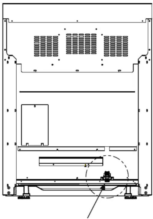
Figure 9: Location of Gas Supply Inlet Connection
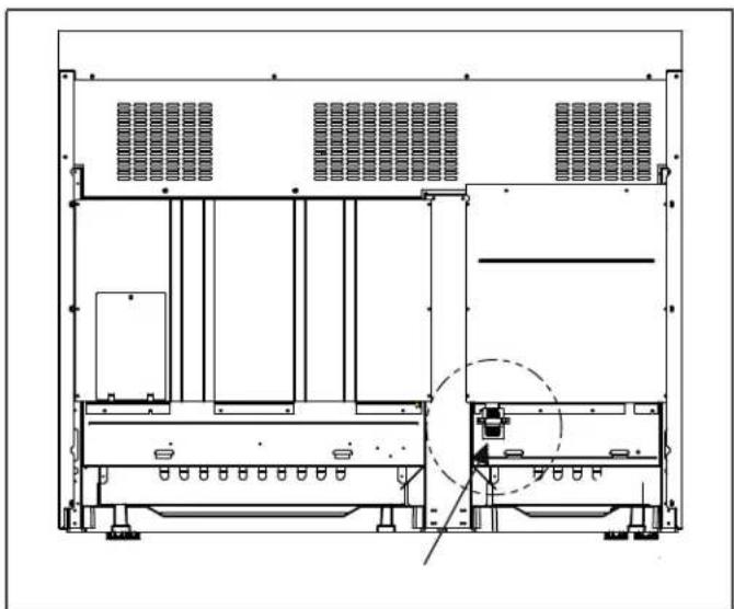
Figure 10: Location of Gas Supply Inlet Connection on 48" Ranges
Step 6: Electrical Requirements, Connection & Grounding
Before installing, turn power OFF at the service panel. Lock service panel to prevent power from being turned ON accidentally.
| Chart B: Electrical Supply Circuit Requirements | ||||
| MODEL TYPE | VOLTAGE | CIRCUIT RATING | FREQUENCY PHASE | |
| 30" 120 VAC | 10 Amps 60 Hz. Single | |||
| 36" 120 VAC | 10 Amps 60 Hz. Single | |||
| 36" with griddle 120 | VAC 20 Amps 60 Hz. Single | |||
| 48" with griddle 120 | VAC 20 Amps 60 Hz. Single | |||
- For these gas range models, a neutral supply wire must be provided from the power source (breaker/fuse panel) because critical range components, including the surface burner spark reignition modules, require 120 VAC to operate safely and properly.

WARNING
An improper 120 VAC power supply will cause malfunction, damage to this appliance, and possibly create a condition of shock hazard.
-
If the correct power supply circuit is not provided, it is the responsibility and obligation of the installer and user to have proper power supply connected. This must be accomplished in accordance with all applicable local codes and ordinances by a qualified electrician. In the absence of local codes and ordinances, the power supply connection shall be in accordance with the National Electrical Code.
-
Observe all governing codes and ordinances when grounding. In the absence of these codes or ordinances observe National Electrical Code ANSI/NFPA No. 70 current issue.
- Electric wiring diagrams and schematics have been placed in the toe kick area of the range for access by a qualified service technician.
Before you plug in an electrical cord, be sure all controls are in the OFF position. - For appliances equipped with a cord and plug, do not cut or remove the ground prong. It must be plugged into a matching grounding type receptacle to avoid electrical shock. If there is any doubt as to whether the wall receptacle is properly grounded, the customer should have it checked by a qualified electrician.
- Installer — show the owner the location of the circuit breaker or fuse. Mark it for easy reference.
Important:
Dedicated 20 AMP service is required for range with electric griddle.
Step 7: Backguard Installation
- The backguard must be attached before sliding the range into the final, installed position. A Low Back or Pot-and-Pan Shelf must be installed when there is less than 12" clearance from a combustible back wall and the back of the range above the cooking surface.
- A Flush Island Trim is available for covering the back area of the range for island installations; however, the Flush Island Trim can only be used where there is a minimum of 12" horizontal clearance between a combustible back wall and the back of the range.
- The backguard is inserted inside the guide channels on the back of the range, as shown in the illustration. (Remove the griddle plate for sufficient installation clearance on griddle models.) Using a T-20 size Torx driver, fasten the backguard with four (4) Torx-head screws to the range's side panels, two (2) screws to the range's back panel, and four (4) screws to the area around the cooling blower.
- To secure the front of the backguard, install three (3) of the Torx head screws through the lower front panel of the backguard, into the flange at the back of the range's cooktop.
- The Pot-and-Pan Shelf requires pre-assembly of the top panel to the shell using nine (9) of the enclosed Torx-head screws. For sufficient load strength, YOU MUST attach the two (2) Torx-head screws through the back corners of the top down into the shell.
- The Pot-and-Pan Shelf provides a shelf above the cooktop to keep foods hot or store cooking pans. OBSERVE CAUTIONS.
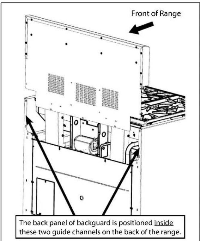
Figure 11: Backguard Installation

WARNING
Fingers or hand could get pinched when installing the backguard. Severe injury could result. Use extreme caution and wear thick protective gloves to avoid potential cut or laceration to finger or hand while sliding the backguard down onto the range.

WARNING
To avoid possible burn or fire hazard, a backguard designed specifically for this range must be installed whenever the range is used.

CAUTION
The Pot and Pan Shelf can get very hot! DO NOT place the following items on top of the Pot and Pan Shelf:
plastics or containers that can melt
- flammable items
- a total load over 30 pounds (13.6kg)
| Chart C: Backguard Kit Model Numbers | ||||
| Range Width 6" Std. Low Back 9" Low Back | 22" Pot and Pan Shelf | Flush Island Trim | ||
| 30" Included with Range N/A PA30GHSH | PA30GITH | |||
| 36" N/A PA36GLBH PA36GHSH Included with Range | ||||
| 48" N/A PA48GLBH PA48GHSH Included with Range | ||||
Step 8: Door Removal and Reinstallation

CAUTION
USE CAUTION WHEN REMOVIDING THE DOOR. THE DOOR IS VERY HEAVY.
- Make sure oven is cool and power to oven has been turned off before removing the door. Failure to do so could result in electrical shock or burns.
The oven door is heavy and fragile. Use both hands to remove or replace the door. - Grasp only the sides of the oven door when removing or replacing it.
- Failure to grasp the oven door firmly and properly could result in personal injury and product damage.
- With the door off, never release the levers and try to close the hinges. Without the weight of the door, the powerful springs will snap the hinges closed with great force.
To Remove the Oven Door:
- Fully open the oven door.
- Flip the hinge clip toward you (see illustration at right).
- Close the door until it stops; the open hinge clip will hold the door about halfway open.
- Grasp the door on the sides. The door is heavy and fragile - always use both hands. Lift the door up and out (there will be some spring resistance to overcome). When the front of the door is high enough, you will be able to pull the door straight out.
- Place the door in a safe and stable location.
To Reinstall the Oven Door:
- Hold door on both sides. Insert hinges into hinge slots. The door will be about halfway open. It may be necessary to press firmly inward on the lower portion of the door, using a rocking motion to fully seat the door's hinges.
- Open door all the way to expose hinge clips. Push hinge clips away from you (toward the oven) until they meet the hinge.
- Close and open the door slowly to test the installation. It should open and close smoothly and be straight, not crooked.
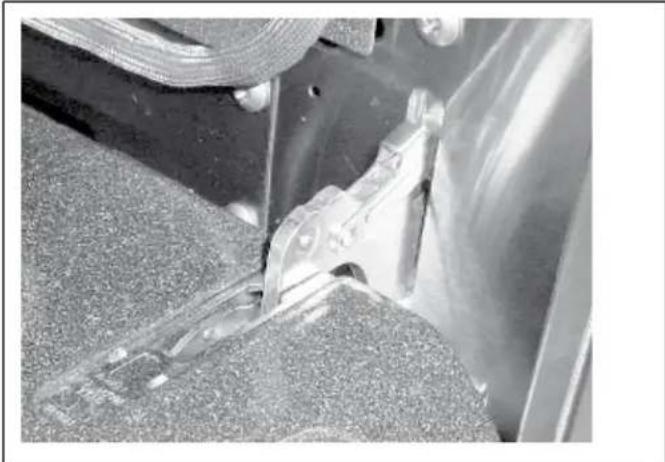
Photo A: Hinge bracket in closed position
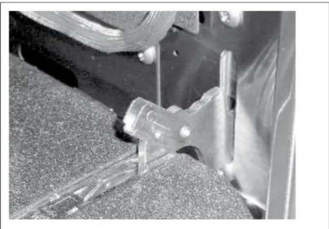
Photo B: Flip hinge clip toward you
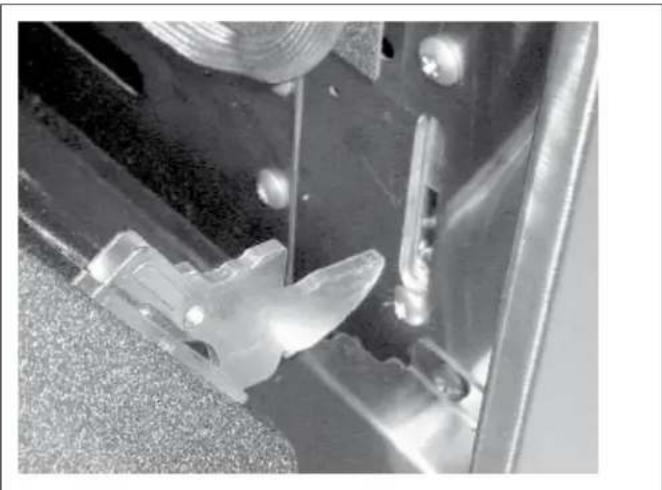
Photo C: Hinge removed from oven
Step 9: Placing and Leveling the Range
- For proper performance, the range must be level. (This is very important for all products that have the griddle feature.)
- The range has four leveling legs that are threaded into the cast aluminum base. The range is leveled by rotating the legs using a 3/8'' socket or a wrench on the hex flats at the top of each leg, or using an adjustable wrench on the flats on the sides of the foot (See Figure 12).
- Progression of the height adjustments should be alternated proportionally between the four legs, until the top edges of the range's side panels are close to matching the countertop height.

CAUTION
The top edges of the range's side panels must be on the same or higher level as the adjacent countertop. If the range is operated while at a lower height relative to the adjacent cabinet, the cabinet could be exposed to excessive temperatures, causing damage to the cabinet and countertop (See Figure 12).
- Final height adjustments of the two rear legs take place before moving the range into its installed position in the cabinet.
- As the range is moved into its final, installed position, verify that one of the rear range feet has properly engaged the Anti-Tip Bracket (See Step 4). This can be verified by viewing through the opening near the floor with the Kick Panel removed.
NOTICE:
Due to their size and weight distribution, the 48^ ranges do not require the use of the Anti-Tip Bracket.
- With the range in the installed position, the final height adjustments are made to the two front legs to ensure proper alignment to the countertop.
Note:
It is assumed that the countertop adjacent to the range has been properly leveled.
- After the Range is properly leveled, replace the Kick Panel and re-install the Oven Door (See "Step 8: Door Removal and Reinstallation" on page 15). It is important that the two (2) screws retaining the Kick Panel are secure to prevent accidental access to hot surfaces.
- Ensure that the burner caps are correctly seated on the burner bases of the range's cooktop.
Griddle Tilt Adjustment (Not All Models)
Check the griddle adjustment by pouring two tablespoons of water on the back of the griddle plate. The water should slowly roll into the grease tray. If not, adjust the two screws under the back of the griddle plate. Start with one half turn counter-clockwise (CCW) of the screws. Further adjustment should be made by one-quarter turn until water slowly flows into the grease tray.
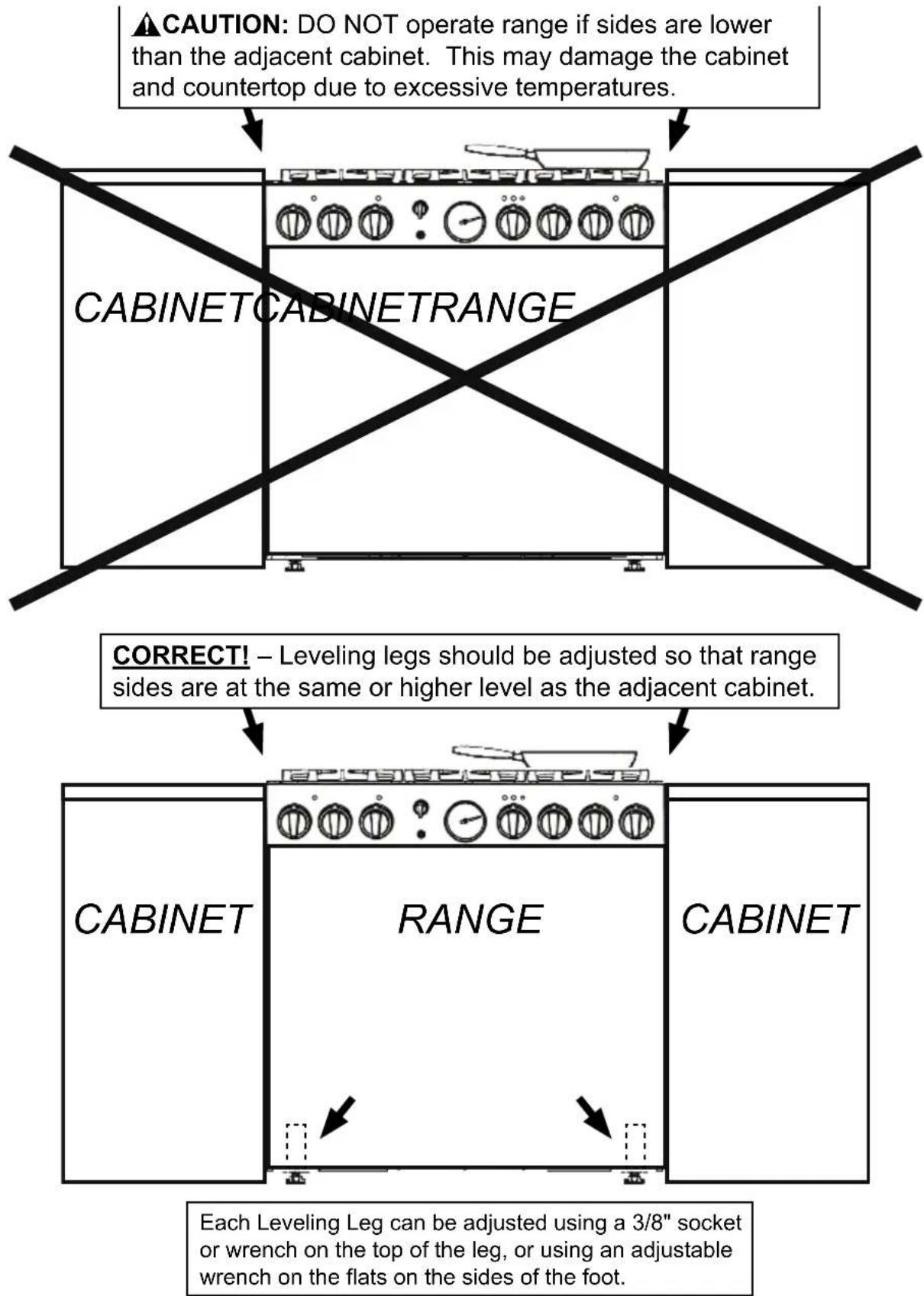
Figure 12: Adjusting the height of the Range
Step 10: Burner Test and Adjustment
Install any loose components, such as burner caps and grates, that may have been removed earlier. Be certain that burner caps seat properly into the burner bases. Before testing operation of the appliance, verify that the unit and the gas supply have been carefully checked for leaks and that the unit has been connected to the electrical power supply. Turn the gas shut-off valve to the open position.
Test Rangetop Burners
Test Burner Ignition. Select a rangetop burner knob. Push in and turn counterclockwise to HI. The ignitor/spark module will produce a clicking sound. Once the air has been purged from the supply lines, the burner should light within four (4) seconds.
Test Flame: High Setting. Turn burner on to HI. See Figure 13 for appropriate flame characteristics.
If any of the rangetop burners continue to burn mostly or completely yellow, verify that the burner cap is positioned properly on the burner base, then retest. If flame characteristics do not improve, call Thermador.
Test Flame: Low Setting. Turn burner on to SIM. Verify that the flame travels complete around the burner. This is known as "carry over". There should be a flame at each burner port and there should be no air gap between the flame and the burner. If any burners do not "carry over", call Thermador.
The two left burners feature XLO, that causes the flame to cycle on and off when the knob is set to the XLO range. This is normal operation.
Repeat these Ignition and Flame Test procedures for each rangetop burner.
Yellow Flames:
Further adjustment is required.
Yellow Tips on Outer Cones:
Normal for LP Gas.
Soft Blue Flames:
Normal for Natural Gas.
Figure 13: Flame Characteristics
If the flame is completely or mostly yellow, verify that the regulator is set for the correct fuel. After adjustment, retest.
Some orange-colored streaking is normal during the initial start-up.
Allow unit to operate 4-5 minutes and re-evaluate before making adjustments.
When Flame is Properly Adjusted:
- There should be a flame at each burner port.
- There should be no air gap between the flame and burner port.
Test Oven Burners
Remove the oven bottom cover. Remove the 4 screws on the sides and the 2 screws on the back, then slide the cover forward while lifting to clear the angled baffle plate mounted to the bottom of the cover.
Note:
The air shutter for the bake burner is set at the factory for fully-open position under all conditions, and does not require adjustment.
Test BakeBurner Ignition
Set the oven to BAKE at 350^ . After 30-75 seconds, the burner will ignite. The burner will stay lit until 350^ is reached and then shut off. From this point forward, the burner will cycle on and off to maintain the temperature.
Test Broil Burner Ignition
Set cooking mode to BROIL. The burner will ignite after 30-75 seconds.
The infrared ceramic broiler does not have an air shutter, so no adjustment is provided.
Replace oven bottom cover. Slide cover into place and reattach to bottom of oven cavity.
Call Thermador if:
- Any of the burners do not light.
- The broil burner or bake burner flame goes out before the oven heats to the desired temperature.
- Any of the burners continue to burn yellow.
Installer Checklist
Final Check List
- Specified clearances maintained to cabinet surfaces.
- Unit Level - front to back - side to side.
- Burner caps positioned properly on burner bases.
- All packaging material removed, including any remaining adhesive-backed foam on brushed-metal surfaces.
- Island trim or backguard attached. Backguard needed if horizontal clearance to combustible materials behind range is less than 12".
- Check door fit to oven cavity. Reinstall door if necessary (See door reinstallation procedure at the bottom of page 15.)
- Kick panel in place and two (2) screws secure.
- INSTALLER:
Write the model number and serial number in the Care and Use Manual (page 34).
Leave the Care and Use Manual and Installation Instructions with the owner of the appliance.
- The griddle plate is correctly positioned, tilted slightly forward. (See page 16 for adjustment procedure.)
Gas Supply
- Connection: 1/2'' N.P.T. with a minimum 3/4'' diameter flex line - suggested length four (4) ft., depending upon local codes.
- The appliance is connected only to the type of gas for which it is certified for use.
- Manual gas shut off valve installed in an accessible location (without requiring removal of range).
- Unit tested and free of gas leaks.
Gas supply pressure does not exceed 14" W.C. (34.9 mb).
If used on propane gas, verify that the propane gas supply is equipped with its own high pressure regulator in addition to the pressure regulator supplied with the appliance.
Electrical
- Receptacle with correct over-current protection is provided for cord connection.
- Proper ground connection.
- Proper polarity at receptacle.
Operation
- Bezels centered on burner knobs, and knobs turn freely.
Each burner lights satisfactorily, both individually and with other burners operating. - Oven door hinges seated and hinge locks in proper position. Door opens and closes properly.
- Burner grates correctly positioned, level, and do not rock.
To Clean and Protect Exterior Surfaces
The stainless steel surfaces may be cleaned by wiping with a damp soapy cloth, rinsing with clear water and drying with a soft cloth to avoid water marks. Any mild glass cleaner will remove fingerprints and smears.
For discolorations or deposits that persist, refer to the Care and Use Manual.
To polish and protect the stainless steel, use a cleaner/ polish such as Stainless Steel Magic®.
DO NOT allow deposits to remain for long periods of time.
DO NOT use ordinary steel wool or steel brushes. Small bits of steel may adhere to the surface causing rust.
DO NOT allow salt solutions, disinfectants, bleaches or cleaning compounds to remain in contact with stainless steel for extended periods. Many of these compounds contain chemicals which could prove harmful. Rinse with water after exposure and wipe dry with a clean cloth.
Table des matieres
Huntington Beach, CA 92649
Questions?
1-800-735-4328
www.thermador.com
Huntington Beach, CA 92649
?Preguntas?
1-800-735-4328
www.thermador.com
jEsparamos oir de usted!
En estas instalaciones, la puerta y el gabineteSEOSEOSEOSEOSEOSEOSEOSEOSEOSEOSEOSEOSEOSEOSEOSEOSEOSEOSEOSEOSEOSEOSEOSEOSEOSEOSEOSEOSEOSEOSEOSEOSEOSEOSEOSEOSEOSEOSEOSEOSEOSEOSEOSEOSEOSEOSEOSEOSEOSEOSEOSEOSEOSEOSEOSEOSEOSEOSEOSEOSEOSEOSEOSEOSEOSEOSEOSEOSEOSEOSEOSEOSEOSEOSEOSEOSEOSEOSEOSEOSEOSEOSEOSEOSEOSEOSEOSEOSEOSEOSEOSEOSEOSEOSEOSEOSEOSEOSEOSEO SEOEO SEOEO SEOEO SEOEO SEOEO SEOEO SEOEO SEOEO SEOEO SEOEO SEOEO SEOEO SEOEO SEOEO SEOEO SEOEO SEOEO SEOEO SEOEO SEOEO SEOEO SEOEO SEOEO SEOEO SEOEO SEOEO SEOEO SEOEO SEOEO SEOEO SEOEO SEOEO SEOEO SEOEO SEOEO SEOEO SEOEO SEOEO SEOEO SEOEO SEOEO SEOEO SEOEO SEOEO SEOEO SEOEO SEOEO SEOEO SEOEO SEOEO SEOEQ
Specifications are for planning purposes only. Refer to installation instructions and consult your countertop supplier prior to making counter opening. Consult with a heating and ventilating engineer for your specific ventilation requirements. For the most detailed information, refer to installation instructions accompanying product or write Thermador indicating model number.
We reserve the right to change specifications or design without notice. Some models are certified for use in Canada. Thermador is not responsible for products which are transported from the U.S. for use in Canada. Check with your local Canadian distributor or dealer.