
CA120 - Receiver Ecler - Free user manual and instructions
Find the device manual for free CA120 Ecler in PDF.
| Product type | Stereo amplifier receiver |
| Output power | 2 x 60 W RMS into 4 Ω |
| Power supply | 100-240 VAC, 50-60 Hz via external adapter |
| Audio inputs | 1 balanced microphone input (Euroblock/jack) with phantom power, 2 stereo line inputs (RCA/minijack), 1 line/microphone input (RCA/jack) |
| Audio outputs | 2 amplified outputs (Euroblock), 1 auxiliary line output (0 dBV) |
| Equalization | Independent bass and treble for microphone/line and lines 1 & 2 |
| Special functions | Auto Standby, Talkover (microphone priority), Noise Gate, External Mute |
| Remote controls | RS-232 (CA-NET protocol), infrared, 0-10 Vdc wall panel (REMOTE RJ-45) |
| LED indicators | Level, clipping, mute, signal presence, standby mode, source selection |
| Cooling | Convection cooling, fanless |
| Dimensions (approx.) | Not specified in the manual (compact size, wall or table mount) |
| Weight (approx.) | Not specified (lightweight, fanless) |
| Maintenance and cleaning | Damp cloth and neutral liquid detergent; do not use solvents |
| Safety | Do not expose to moisture; disconnect before servicing; respect minimum impedance 4 Ω |
| Spare parts and repairability | Servicing by Ecler technical service; no user-accessible parts |
| General information | Compliant with EN55103 (EMC) and EN60065 (safety); directives 73/23/EEC and 2004/108/EC |
Frequently Asked Questions - CA120 Ecler
User questions about CA120 Ecler
0 question about this device. Answer the ones you know or ask your own.
Ask a new question about this device
Download the instructions for your Receiver in PDF format for free! Find your manual CA120 - Ecler and take your electronic device back in hand. On this page are published all the documents necessary for the use of your device. CA120 by Ecler.
USER MANUAL CA120 Ecler
1.1. Compliance with international standards 04
2. INTRODUCTION
0
3. INSTALLATION
3.1. Location and assembly
3.2. Mains connection
3.3. Audio input connections
3.4. Audio output connections
3.5. Remote control options
4.1. Operation and default mode 07
4.2. Special active source selection mode and setting adjustments 08
4.3.AUTO STANDBY Function 09
4.4. LED indicators
4.5. Micro switches on the rear panel 10
4.6. Lock mode
4.7. Restore default settings and update firmware 11
5.CLEANING 1 1
6. LIST OF FUNCTIONS 1 2
7. DIAGRAM OF FUNCTIONS 1 3
8. TECHNICAL CHARACTERISTICS 5
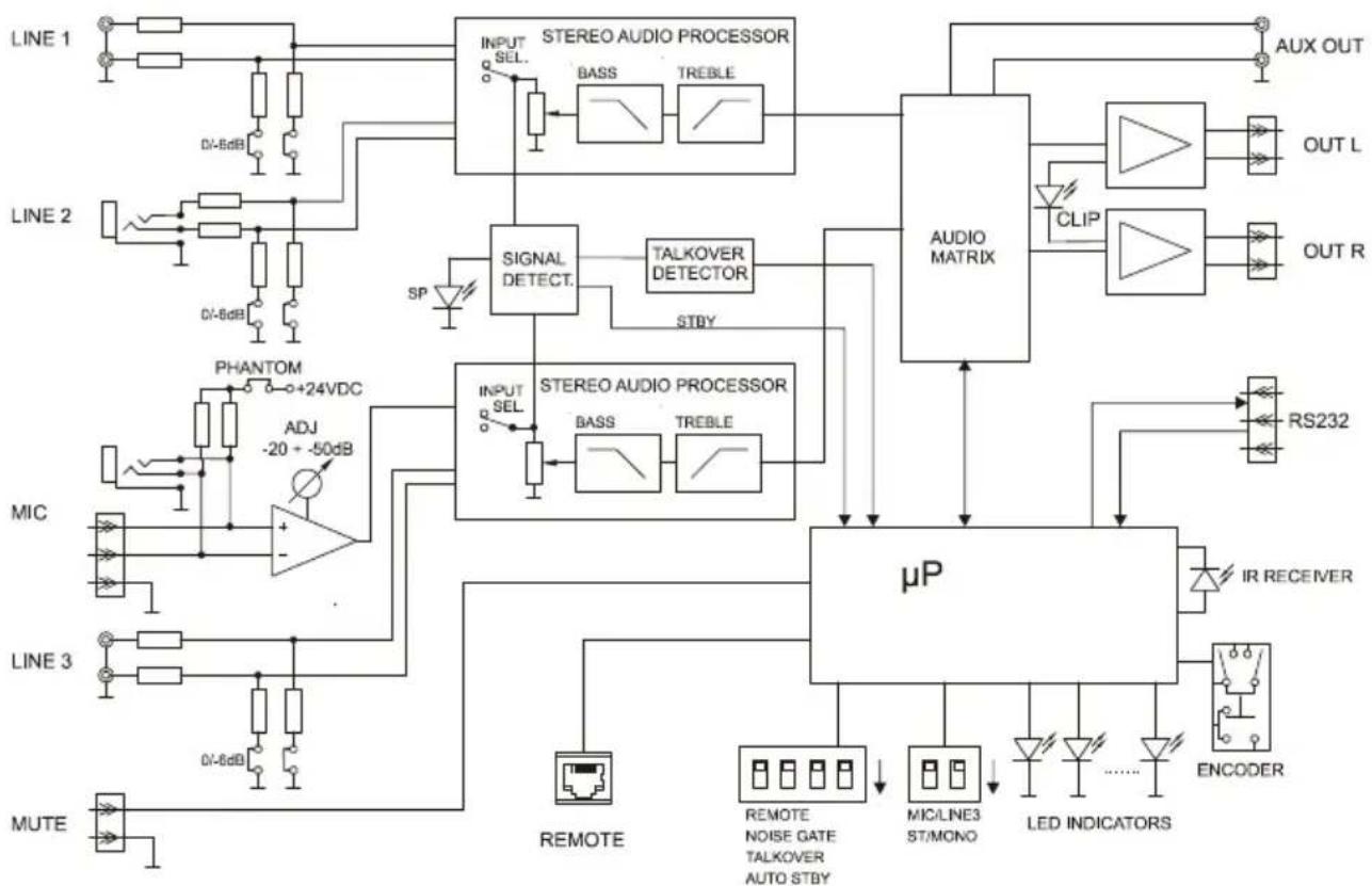
9. BLOCK DIAGRAM 5 1
10. CONFIGURATION DIAGRAM 52
1. IMPORTANT NOTE
Congratulations! You have acquired the result of painstaking design and manufacturing. Thank you for having chosen our CA120 micro amplifier.
In order to get the optimum operation and efficiency from your product, it is VERY IMPORTANT - before you plug anything - to read this manual very carefully and take seriously into account all considerations specified within it.
We strongly recommend that its maintenance be carried out by our Authorised Technical Services.
1.1. Compliance with international standards
The CA120 micro amplifier complies with the following international standards:
EN55103-1 Electromagnetic Compatibility.
Product family standard for audio, video, audio-visual and entertainment lighting control apparatus for professional use
Part 1: Emission
EN55103-2 Electromagnetic Compatibility.
Product family standard for audio, video, audio-visual and entertainment lighting control apparatus for professional use
Part 2: Immunity
EN60065 Audio, video and similar electronic apparatus. Safety requirements
Complying with the requirements of directives 73/23/EC and 2004/108/EC
2. INTRODUCTION
The CA120 is a very small stereo amplifier with numerous remotely controlled functions (RS-232 serial port, infrared receiver, 0-10 VDC remote control port), and is ideal for integrating audiovisual applications with other devices: educational classes, meeting rooms and multimedia presentations, business premises, etc.
Main characteristics:
- 2 × 60 W RMS @ 4 amplifier
Universal external power supply - AUTO STANDBY function: in the absence of an audio signal the unit automatically goes into STANDBY mode, minimising power consumption
- Lightweight, silent, high-performance amplifier (fan-free convection cooling)
- Suitable for stereo and parallel (mono)
- 1 switchable balanced mic / unbalanced line input, with high quality microphone preamplifier, phantom power supply, noise gate and "talkover" function or priority over the rest of input
- 2 stereo lines (not balanced)
2-band independent tone control (Bass, Treble) for the microphone / line 3 and line 1&2 input connection.
Auxiliary output for liaison with other amplifiers or external audio devices - Local control by digital rotary knob ("encoder")
- Remote control by infrared remote control
- Remote control by WPmVOL or WPmVOL-SR (0-10 VDC) wall panel
- RS-232 control port, compatible with EclerCOMM software (free) and control protocol CA-NET
MUTE port to silence the entire unit by closing external contact
3. INSTALLATION
3.1. Location and assembly
The CA120 is suitable for installation on a wall or under a surface (table, shelf, cupboard, etc.), thanks to its design and layout of its connectors, controls and LED indicator lights.
3.2. Mains connection
The amplifier is powered by alternating current through its external power source: 100-240 VAC and 50 - 60Hz
This apparatus must be earthed through its mains cable (earth resistance, Rg = 30 , or lower). The atmosphere should be as dry and dust free as possible. Do not expose the unit to rain or water splashes. Do not place liquid containers or incandescent objects like candles on top of the unit.

Should any work or connection / disconnection task be done, always disconnect the unit from the mains supply. There are no elements that can be manipulated by the user inside the amplifier.
To avoid buzzing, do not allow the power cable to intertwine with the shielded cables that transport the audio signal.
3.3. Audio input connections
The CA120 accepts two types of signals in its input channels:
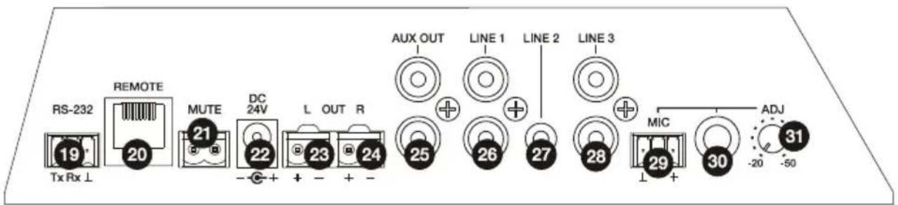
- Microphone (MIC): has a balanced Euroblock or jack type connection, ready to accept a signal level between -20dBV y -50dBV, with adjustable sensitivity with the ADJ control
NOTE: the microphone input has a phantom power supply to power condenser microphones, activated by internal bridge (see section 10. CONFIGURATION DIAGRAM).
- Line signals (LINE1, LINE2, LINE3): they have unbalanced minijack or double RCA type stereo connections. They are prepared for input of between -6dBV and 0dBV, with input sensitivity that can be adjusted by internal port (see section 10. CONFIGURATION DIAGRAM). You can connect signals from CD players, radio tuners, mixing consoles, media players, the audio outputs of PCs and tablets, etc. to these connections.
NOTE: Turntables CANNOT BE CONNECTED directly to this device because none of the inputs have an RIAA preamp.
The CA120 has the following operating modes according to the input sources selected as active:
LINE1: only LINE1 input is sent to the mix bus to be amplified and delivered to the L and R OUT outputs
LINE2: only LINE2 is sent to the mix bus to be amplified and delivered to the L and R OUT outputs
LINE3/MIC: only microphone (MIC) / line (LINE3) input is sent to the mix bus to be amplified and delivered to the OUT L and R outputs
LINE1 + LINE3/MIC: the LINE1 and LINE3/MIC inputs are mixed, amplified and delivered to the L and R OUT outputs. If the TALKOVER function is active, the

LINE3/MIC signal attenuates to that of the LINE1 when it exceeds the activation threshold
- LINE2 + LINE3/MIC: the LINE2 and LINE3/MIC inputs are mixed, amplified and delivered to the L and R OUT outputs. If the TALKOVER function is active, the LINE3/MIC signal attenuates to that of the LINE2 when it exceeds the activation threshold
Select one of the 5 work modes in special selection mode with the rotating knob on the front (see section 4.2. Special selection mode of active sources and adjusting settings for details of the full procedure).
3.4. Audio output connections
The amplified output (OUT L and R) have Euroblock connectors.
The connection cable that connects the CA120 connectors and the speakers should be good quality, with a suitable cross section and as short as possible.
The outputs can operate in stereo mode or mono (same signal L + R and both channels). These are selected using the micro switches STEREO-MONO on the rear panel (see section 7. DIAGRAM OF FUNCTIONS for more information).
Remember that the minimum work impedance for the amplifiers in mono or stereo mode is 4 . For correct operation of the CA120, under no circumstances must you work with impedance lower than specified above.
Additionally, the CA120 has an unamplified auxiliary output (AUX OUT) which makes it possible to connect it to amplifiers or with other external devices. The auxiliary output AUX OUT has a line level signal (0dBV) which is an unamplified replica of the signal delivered to the terminals OUTPUT L y R.
3.5. Remote control options
- REMOTE port: the RJ-45 REMOTE type connector allows the connection of a WPlVOL or WPlVOL-SR (control 0-10 VDC) wall control panel to adjust the general output volume and/or to select one of the five active work source modes (LINE1, LINE2, LINE3/MIC, LINE1 + LINE3/MIC, LINE2 + LINE3/MIC). The connection is made by a standard CAT5 cable between the WPlVOL or WPlVOL-SR wall panel and the REMOTE CA120 connector.
Because there is a CA120 WPM type control as well as other types of control (front knob, infrared control and serial port control) the most recent adjustments by any of these methods will prevail. For example, if an active source is selected and/or a volume adjustment is made using the WPMVOL-Sr wall panel connected to the REMOTE port, and then these settings are adjusted using the front control, the adjustment made with the frontal control will prevail. In this case, when the wall panel position is adjusted again, the CA120 will change to the values indicated, and so on and so forth.
- MUTE port: The MUTE connector makes it possible to connect a power free contact to totally silence the CA120 if an external device works on it (example: a emergencies and centralised evacuation warning system).
- RS-232 port: the serial communication port RS-232 allows remote management of the CA120 from a computer through the EclerCOMM software or CA-NET protocol from an external control system supporting this protocol. See the CA-NET protocol manual for detailed information on the connection and syntax of the commands supported. The connection has the following specifications:
Baud rate: 9600 (fixed, without auto negotiation)
Data bits: 8
。 Parity: None
o Stop bits: 1
Flow control: None
| WIRING RS-232 - DB9 | |
| RS-232 CA120 DB9 | |
| Tx Pin 2 (RxD) | |
| Rx Pin 3 (TxD) | |
| Gnd Pin 5 (Signal Gnd) | |
- Receiver IR: the built-in IR receiver gives general volume control of the CA120 and its MUTE ON / OFF function from the REVO-IR remote control included with the unit.
Start up the CA120 by connecting the equipment to an external power source to which the DC 24V connector of the CA120 has already been connected. The LED indicator ON/STBY immediately lights up on the front panel. We recommend you turn on all the devices in the following order: sound sources, mixer, equalisers, active filters and processors and, finally power amplifiers. Powering off should be done by following the exact reverse sequence. Following this order, the introduced noise due to turning on or switching off the devices will not affect those further on in the chain and will be inaudible.
The system defaults to volume adjustment mode. In this mode, the VOL/MUTE knob on the front panel acts on the general output volume of the CA120. This controller has a maximum of 64 steps between the unit's minimum and maximum volume. When turned, it will adjust the volume while the LED LEVEL light is flashing. When the controller is turned to the left or to the right, this flashes while the output volume increases or decreases. The light stops flashing when it reaches either end of the scale and it is no longer possible to increase or decrease the volume of the unit.
Quickly press the VOL/MUTE controller to activate/deactivate the mute function of the unit (MUTE ON/OFF). The MUTE LED lits when the mute function is activated.
If you adjust the volume using the infrared remote control, the LED LEVEL y MUTE visual indicators are exactly the same as those seen when adjusting these with the knobs on the front panel.

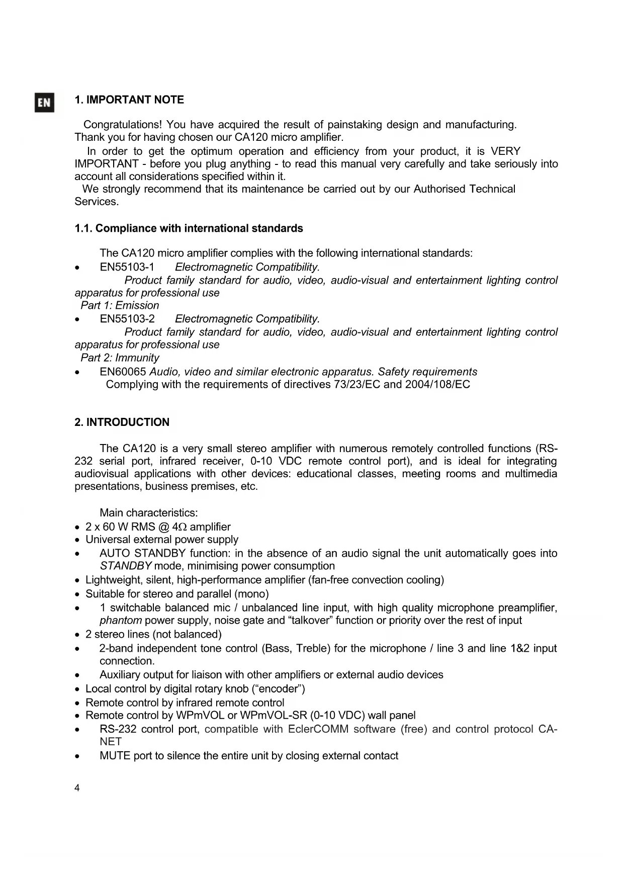
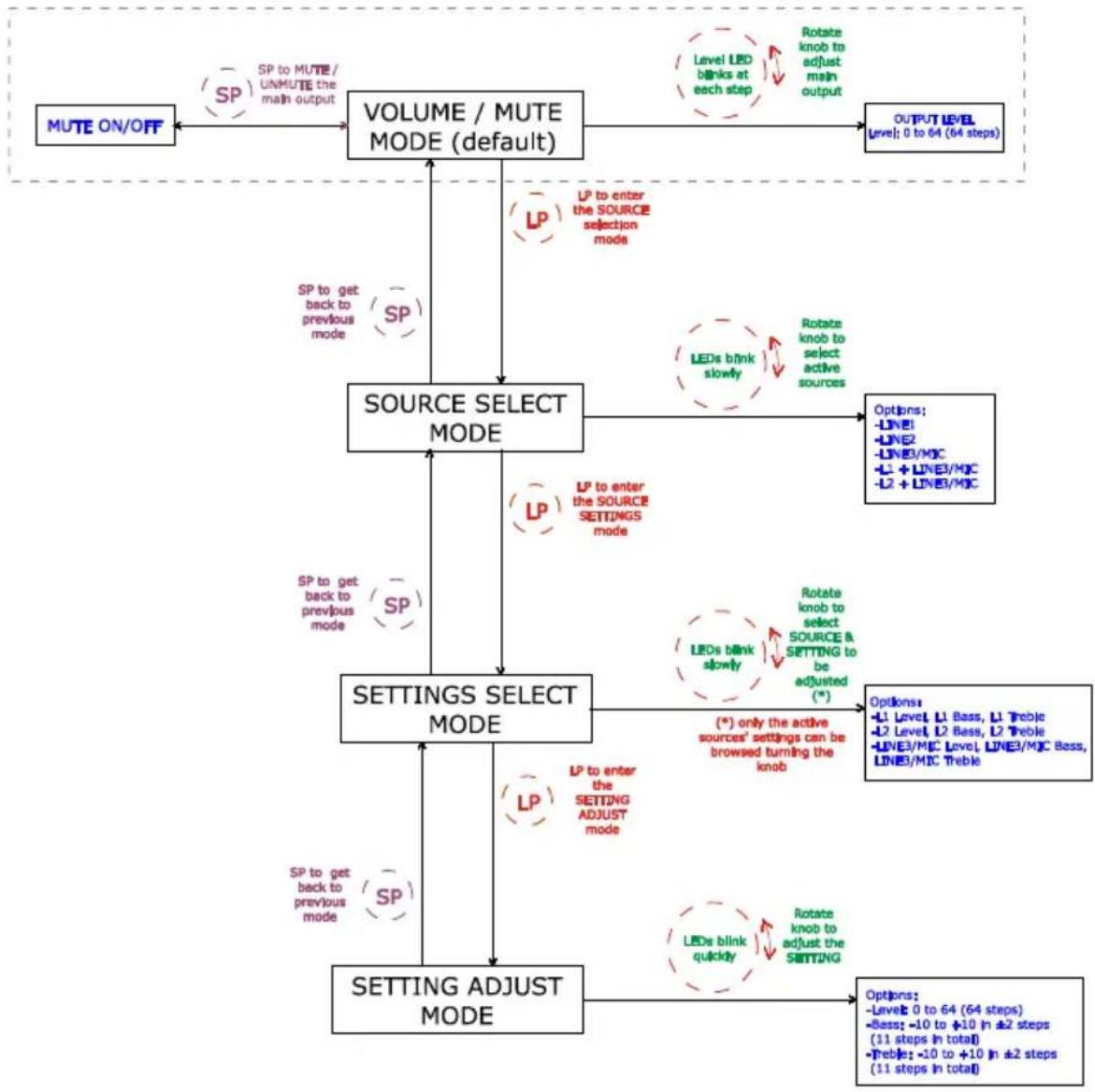
4.2. Special active source selection mode and setting adjustments
Use the knob on the front panel to access special modes for selecting active sources and adjusting levels and equalization (bass and treble). You can access these modes by holding in the knob for a certain time and then turning it. By adjusting the level of each source you can mix the signal from the microphone or line (LINE3/MIC) and another line (LINE1 or LINE2), and the result of this mix will be controlled by the general output volume of the unit together, in other words, respecting the relative levels set of each source.
The full procedure for accessing and operating in these special modes and the options available in each are set out in the following graph:
CA120 adjustments with front knob browser
SP: Short Press (press the VOL/MUTE knob briefly, less than 0,5 seconds)
LP: Long Press (press & hold the VOL/MUTE knob for more than 2,5 seconds)
Notes:
- If the device is in special mode for 10 seconds and the front knob is not touched, the equipment automatically reverts to VOL/MUTE mode.
- In tone control mode, when you turn the knob in either direction it flashes fast while the gain of the affected tone increases. When either end of the scale is reached (-10 o +10dB) or when it goes through the centre point (0dB) it flashes more slowly.
4.3.AUTO STANDBY Function
The AUTO STANDBY function (idle or low consumption mode) means you can install the CA120 in inaccessible places and leave the device connected to the mains power supply permanently because when no signal is detected, it automatically goes into standby mode, saving energy.
To enable AUTO STANDBY use the micro switch with the same name on the rear panel of the unit (see section 7. DIAGRAM OF FUNCTIONS). When activated, if there is no audio signal in any of the inputs (or the signal is very weak, below the activation threshold), the CA120 automatically goes into STANDBY mode, and the ON/STBY on the front panel of the device goes orange. When a valid audio signal is detected in any of the inputs, the CA120 leaves standby mode and starts operating normally again and the ON/STBY LED goes green.
When you enable AUTO STANDBY mode with the micro switch (position ON) one of two things happens:
a) There is NO audio signal in the inputs. Result: the amplifier immediately goes into AUTO STANDBY mode
b) There is an audio signal in the inputs. Result: the amplifier stays active
When the amplifier goes into AUTO STANDBY mode, all the LED indicators go out with the exception of ON/STBY. If the amplifier is in STANDBY mode and you turn the VOL/MUTE knob to adjust the volume or activate the MUTE function, the LED lights will come on for a short time then go out again. Remember that the first acting on the VOL/MUTE knob, this will only reset the LED indicators, and will not change any of the settings.
When the unit is a special mode (source selection or setting adjustment) the LED indicators will not go out even if the amplifier is in AUTO STANDBY mode.
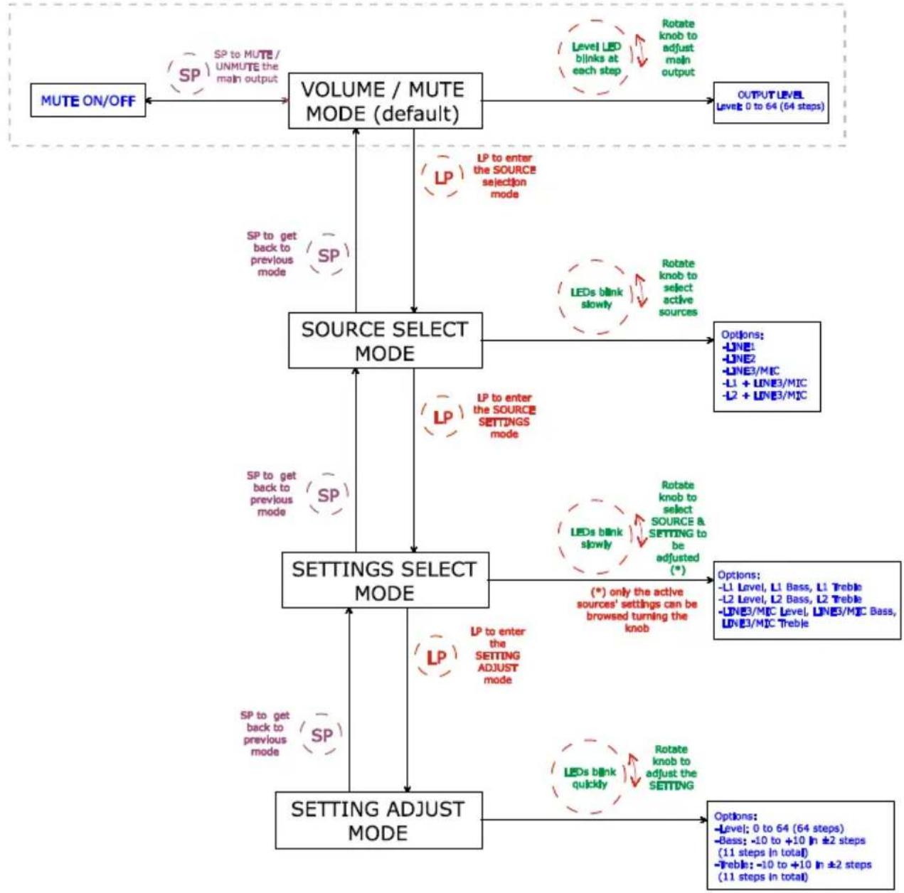
4.4. LED indicators
- SP: The signal presence or SP LED indicator shows that there is a signal in the amplifier input. This lights up when the input level reaches the established detection threshold.
- CLIP: The saturation or CLIP LED indicator comes on when the signal delivered to the speakers is close to the amplifier's clipping or saturation level. Input signals should be set to ensure the CLIP (saturation or cut off) indicators never stay on, but that they do so at most to the beat of the lowest sound frequencies. Otherwise the amplified signal will be distorted with low quality and low intelligibility.
Note: If the input signal is too high, the CLIP indicator lighting up very frequently over a short time interval (a few seconds), the amplifier may go into protection mode, being muted to return to normal operation in a short time
MUTE: This lights up when the MUTE function is active (silent mode)
- ON/STBY: the green light comes on when the equipment is in normal operating mode and it goes orange when it is in standby or low consumption mode (STANDBY).
LEVEL: This flashes when you adjust the general level of the device. It also lights up during special adjustment modes, input levels (see section 4.2. Special active source selection mode and setting adjustments)
BASS: This lights up during special adjustment modes bass frequencies (see section 4.2. Special active source selection mode and setting adjustments) - TREBLE: This lights up during special adjustment modes, treble frequencies (see section 4.2. Special active source selection mode and setting adjustments)
LINE1, LINE2, LINE3/MIC: These light up during special modes, selection of active sources and adjustments (see section 4.2. Special active source selection mode and setting adjustments)
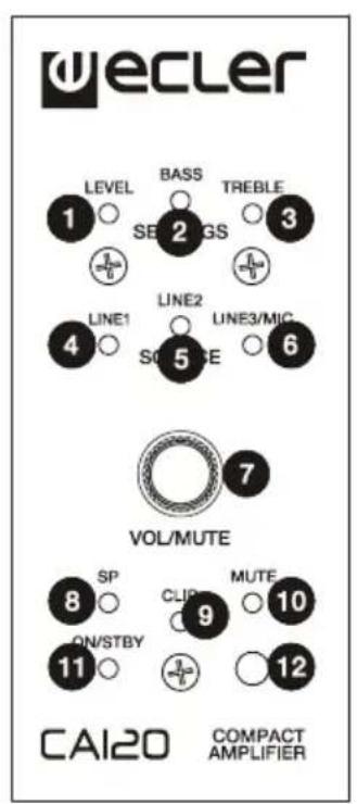
4.5. Micro switches on the rear panel
- REMOTE: Turn on (ON) the remote control from the WPmVOL or WPmVOL-SR wall panel connected to the REMOTE port.
- NOISE GATE: Turn on (ON) or turn off the noise gate function for the LINE3/MIC input. When this function is active the microphone input is muted whilst there is no signal above the function activation threshold, so the equipment rejects background noise captured by the microphone connected to it.
- TALKOVER: On or off according to the priority of the LINE3/MIC input over the line inputs (LINE1 or LINE2). When the TALKOVER function is on, the LINE3/MIC signal will attenuate the selected line (LINE 1 or 2) when the activation threshold set is reached.
- AUTO STANDBY: Switch the AUTO STANDBY function on (ON) or off. When the function is on, the CA120 will automatically go into STANDBY or low consumption mode in the absence of audio signals in its inputs.
STEREO/MONO (ST/MONO): Select the work mode of the amplified outputs of the unit:
ST:Work in stereo mode L/R
MONO: Work in MONO mode, both channels amplifying the L+R signal.
4.6. Lock mode

To switch the CA120 lock mode on or off hold in the VOL/MUTE control for 10 seconds from the VOL/MUTE mode. The LED SETTING indicators will flash 3 times to indicate that lock mode is now on. When in lock mode the device cannot be managed using the VOL/MUTE control (it will flash three times to show that it is in that mode when you turn the knob). This will protect the equipment from unwanted handling until it is restored to normal operation after holding the VOL/MUTE control in for a further 10 seconds (the LED SETTING indicators will flash twice to show that the lock mode is off).
Note: once lock mode is activated it will stay activated even when the equipment is turned off and on again. It will stay in lock mode until the VOL/MUTE control is held in for 10 seconds again.
4.7. Restore default settings and update firmware
If you would like to restore the CA120 to factory settings, follow this procedure:
- Unplug the equipment then press and hold the knob in.
- Plug back the unit without releasing the knob. The MUTE LED indicator will flash.
- Wait a few seconds and then switch the CA120 off again.
- The next time you turn it on, the factory settings will be in the memory.
Note: for instructions on how to update the unit's firmware, see the product web page at www.ecler.com, where you will find the update software utility and instructions on how to proceed.
5. CLEANING
The CA120 must not be cleaned with solvents or abrasive substances which may damage the prints. Clean using a cloth moistened in water and a neutral liquid detergent, then dry with a clean cloth. Under no circumstances allow water to enter any of the orifices in the equipment.
6. LIST OF FUNCTIONS
- LEVEL indicator light
- BASS indicator light
- TREBLE indicator light
- LINE1 indicator light
- LINE2 indicator light
- MIC indicator light
- VOL/MUTE knob
- SP input signal presence indicator light
- CLIP indicator light
- MUTE indicator light
- ON/STBY on or standby indicator light
- REMOTE, remote control receiver
- REMOTE micro switch
- NOISE GATE micro switch
- TALKOVER micro switch
- AUTO STANDBY micro switch
- MIC/LIN3 micro switch
- STEREO/MONO micro switch
- Remote control by protocol CA-NET, RS-232
20.RJ-45,REMOTE connector - MUTE remote control
- DC24V power connector
- OUT L amplified output
- OUT R amplified output
- AUX OUT
- RCA input line, LINE1
- Mini jack input line, LINE2
- RCA input line, LINE3
- Microphone input, MIC
- Microphone jack, MIC
- MIC input sensitivity setting
- Mute key
- Volume up key
- Volume down key
ES
1. NOTA IMPORTANTE
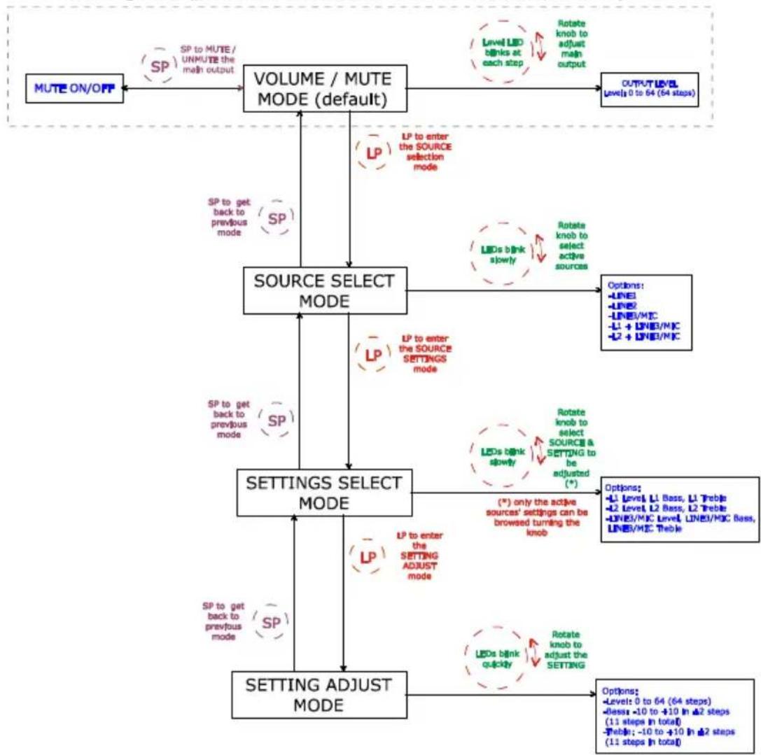
CA120 adjustments with front knob browser
SP: Short Press (press the VOL/MUTE knob briefly, less than 0,5 seconds)
LP: Long Press (press & hold the VOL/MUTE knob for more than 2,5 seconds)
Notas:
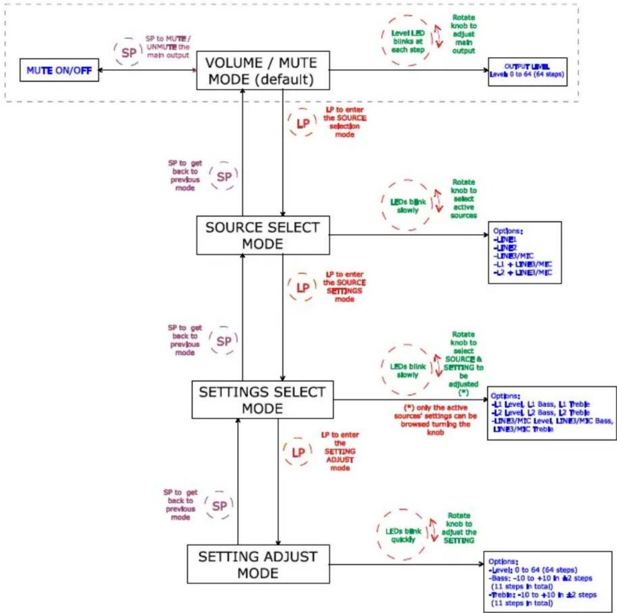
CA120 adjustments with front knob browser
SP: Short Press (press the VOL/MUTE knob briefly, less than 0,5 seconds)
LP: Long Press (press & hold the VOL/MUTE knob for more than 2,5 seconds)
Remarques :
Baudrate: 9600 (fest, ohne "autonegotiation")
Data bits: 8
Parity: None
o Stop bits: 1
Flow control: None
| KABELVERBINDUNG RS-232 - DB9 | |
| RS-232 CA120 DB9 | |
| Tx Pin 2 (RxD) | |
| Rx Pin 3 (TxD) | |
| Gnd Pin 5 (Signal Gnd) | |
CA120 adjustments with front knob browser
SP: Short Press (press the VOL/MUTE knob briefly, less than 0,5 seconds)
LP: Long Press (press & hold the VOL/MUTE knob for more than 2,5 seconds)
Hinweise:
Frequency response 15Hz - 30kHz (-3dB)
THD+Noise @ 1kHz Full Power SPEAKER OUT <0.15%
THD+Noise AUX OUT <0.02%
Channel crosstalk @ 1kHz >65dB
Inputs Sensitivity nom/Impedance LINE1
LINE2 0dBV (-6dBV^*) / >8k
LINE3 0dBV (-6dBV^*) / >8k
MICRO -20 to -50dBV/>1kΩ
CMRR MICRO(BAL) >65dB @1kHz
Outputs Level/Minimum Load AUX OUT
Tone control (LINE & MIC) BASS
100Hz ±10dB
-2dBV/10kΩ
TREBLE 6KHz
Signal Noise Ratio
LINE >85dB
Talkover
MIC
Microphone Noise Gate
TIME 2 Sec**
Phantom voltage
DEPTH -30dB**
RS-232
20-30 below max.**
+24VDC/10mA max.*
ANALOG REMOTE (0-10V. based)
BAUD RATE 9600 (fixed)
INFRARED REMOTE
DATA 8
PARITY NONE
Mains (Using supplied DC adapter)
STOP
FLOW
Power consumption (pink noise, 1/8 power @ 4ohm)
Volume & Input/preset**
Power consumption (pink noise, 1/3 power @ 4ohm)
selection
Power consumption Stand By (time 2 minutes)
Volume & Mute
Dimensions WxDxH
90-264VAC 47-63Hz
Weight
33VA/24W
Internally selectable *Software selectable
58VA/52W
<2.5W
160x210x48mm
950g
- BLOCK DIAGRAM 9. DIAGRAMA DE BLOQUES
- SCHEMA FONCTIONNEL 9. BLOCKSCHALTBILD
- CONFIGURATION DIAGRAM 10. DIAGRAMA DE CONFIGURACION
- SCHEMA DE CONFIGURATION 10. KONFIGURATIONSÜBERSICHT


- INTRODUCTION
- INSTALLATION
- IMPORTANT NOTE
- Compliance with international standards
- Location and assembly
- Mains connection
- Audio input connections
- Audio output connections
- Remote control options
- Special active source selection mode and setting adjustments
- CA120 adjustments with front knob browser
- Notes:
- 4.3.AUTO STANDBY Function
- LED indicators
- Micro switches on the rear panel
- Lock mode
- Restore default settings and update firmware
- CLEANING
- LIST OF FUNCTIONS
- NOTA IMPORTANTE
- Notas:
- Remarques :
- Hinweise:
Brand : Ecler
Model : CA120
Category : Receiver