FastResponse K1647 - Steam cleaner KOHLER - Free user manual and instructions
Find the device manual for free FastResponse K1647 KOHLER in PDF.
Download the instructions for your Steam cleaner in PDF format for free! Find your manual FastResponse K1647 - KOHLER and take your electronic device back in hand. On this page are published all the documents necessary for the use of your device. FastResponse K1647 by KOHLER.
USER MANUAL FastResponse K1647 KOHLER
WARNING: Risk of personal injury. Do not install the Steam Control User Interface outside the
steam enclosure. The User Interface must be installed within the enclosure to allow the sensors to regulate the temperature and control the flow of steam.
DANGER: Risk of electrocution. Disconnect the electricity to the working area at the main breaker
panel before performing these installation steps.
WARNING: Risk of personal injury. If you become uncomfortable while taking a steam bath, you
should power off the unit. Cool off with the shower, open the door, or exit the unit.
WARNING: Risk of allergic reaction. Before adding any oils, aromatic therapies, or skin care
products to the aromatherapy well, make sure they will not cause an allergic reaction to the user.
WARNING: Risk of personal injury. This steam bath may not be suitable for use if you are
pregnant, have a heart condition, have high blood pressure, have circulatory problems, are under the influence of alcohol, are taking drugs or are under the care of a physician. A steam bath can put undue stress on the body, as does any hot bath, shower, or sauna.
WARNING: Risk of personal injury. DO NOT consume alcoholic beverages or take
medications/drugs prior to or when using the steam bath. Alcohol and drugs affect mental judgement and inhibit bodily functions such as heartbeat and respiration, resulting in potentially dangerous effects.
WARNING: Risk of injury to children. Do not allow children to use this unit unless they are
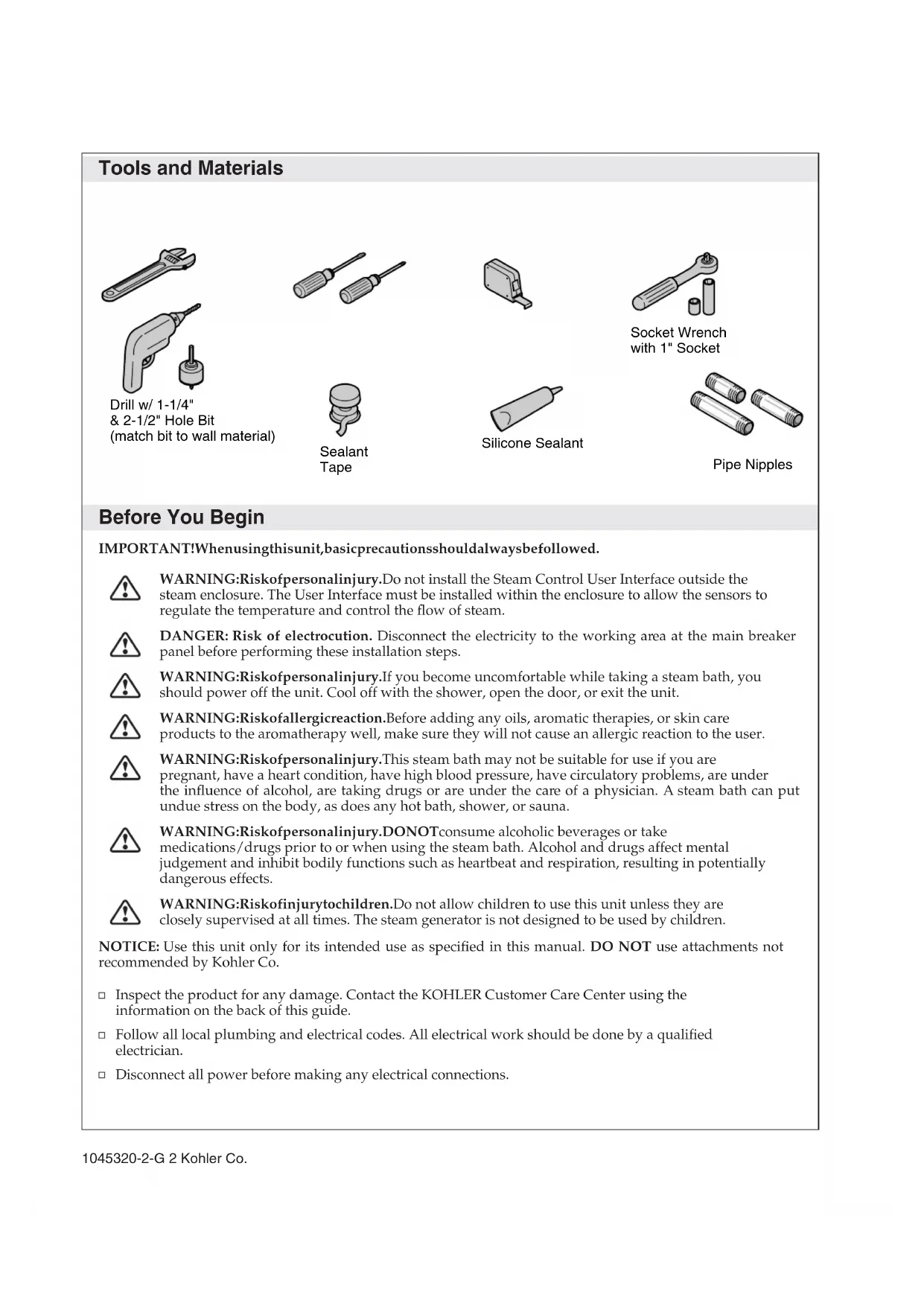
closely supervised at all times. The steam generator is not designed to be used by children. NOTICE: Use this unit only for its intended use as specified in this manual. DO NOT use attachments not recommended by Kohler Co. Inspect the product for any damage. Contact the KOHLER Customer Care Center using the information on the back of this guide. Follow all local plumbing and electrical codes. All electrical work should be done by a qualified electrician. Disconnect all power before making any electrical connections. Silicone Sealant Drill w/ 1-1/4" & 2-1/2" Hole Bit (match bit to wall material) Sealant Tape Socket Wrench with 1" Socket Pipe Nipples 1045320-2-G 2 Kohler Co.Before You Begin (cont.) Kohler Co. reserves the right to make revisions in the design of products without notice, as specified in the Price Book. Kohler Co. 3 1045320-2-GReview Layout
WARNING: Risk of personal injury. Do not install the Steam Control User Interface outside the
steam enclosure. The User Interface must be installed within the enclosure to allow the sensors to regulate the temperature and control the flow of steam.
WARNING: Risk of scalding. Do not locate the steam head near a seat or bench, as the steam head
is hot during operation and may scald the user if touched. NOTICE: It is recommended to locate the control kit and steam head on the same wall as the plumbing controls. For optimum performance, do not locate the control kit directly above the steam head. Locate the steam head 6″ (15.2 cm) above the floor and a minimum of 4-1/2″ (11.4 cm) from the threshold. The steam head should always be located as far away from the seating area as possible. Review the layout determined during the steam generator installation. See the steam generator installation guide for more information. Modules - Single Steam Head
(15.2 cm) 60" (152.4 cm) K-1687 11" (27.9 cm) 21" (53.3 cm) 21" (53.3 cm) Control Kit 4-1/2" (11.4 cm) 60" (152.4 cm) Drain End K-9486/K-9489 4-1/2" (11.4 cm) 21" (53.3 cm) 60" (152.4 cm) Drain End K-9488/K-9496 Steam Head Steam Head 21" (53.3 cm) Steam Head
(15.2 cm) Steam Head 21" (53.3 cm) Control Kit 60" (152.4 cm) 21" (53.3 cm) Steam Head
(15.2 cm) Control Kit 4-1/2" (11.4 cm) Drain End Steam Head 1045320-2-G 4 Kohler Co.Review Layout (cont.) Identify the model number of your shower module in the illustration. If necessary, consult the Homeowners Guide included with your shower module to verify the model number. If the dimensions for your particular model are not shown, refer to the ″Custom Shower Application″ illustration in the ″Prepare the Site″ section. Determine the location of the control kit and steam head based on the roughing-in dimensions illustrated. Dimensions given in the rough-in information are crucial for proper installation. Install the Steam Control User Interface inside the steam enclosure. Locate the control kit and steam head in the location indicated. All measurements are from the inside of the module. Custom Shower Applications Install the Steam Control User Interface inside the steam enclosure. The steam head should be located 6″ (15.2 cm) above the shower floor or 4-1/2″ (11.4 cm) above the threshold. Ensure clearance between the steam line and any surrounding surfaces. Kohler Co. 5 1045320-2-G1. Prepare the Site NOTE: This section continues the installation as described in the steam generator installation instructions. Refer to the steam generator installation instructions guide for more information, if required. NOTE: If two steam heads are required, ensure there is at least 12-1/2″ (31.8 cm) between the center of each hole. The steam heads do not need to be located in the same area.Install the finished wall material.Mark the temporary pipe nipple at the location of the finished wall surface.Remove the temporary pipe nipple from the elbow.Drill or cut a 2-1/2″ (6.4 cm) hole centered around the elbow in the wall. Wall Stud 2-1/2" (6.4 cm) 6" (15.2 cm) from Floor Provide clearance from wall. Mark the nipple even with finished wall. Temporary Nipple Wall Stud 1045320-2-G 6 Kohler Co.2. Install the Steam Head(s) NOTICE: Do not obstruct the steam head with shut-off valves, plugs, or caps. Subtract 1-1/4″ (3.2 cm) from the marked length to determine the appropriate nipple size. Choose a nipple length within 1/8″ of the appropriate nipple size. Apply thread sealant to the threads on one side of the nipple and thread that side into the steam head housing until hand-tight. Apply thread sealant to the threads on the other end of the nipple. Position the gasket around the steam head housing so that it will be between the finished wall and the steam head housing flange. Usea1″ socket to thread the steam head housing assembly into the elbow in the wall. Make sure the gasket is compressed and a good seal has been achieved around the edges of the steam head housing. Use an appropriate sealant to achieve a watertight seal if needed. Press the steam head assembly into the steam head housing with the aromatherapy well positioned on the top of the steam head. Steam Head Steam Housing 1/2" NPT Elbow Steam Head Lip Wall Aromatherapy Well Nipple Steam Housing Apply thread sealant. Apply thread sealant. Kohler Co. 7 1045320-2-G3. Install the Steam Control
WARNING: Risk of personal injury. Do not install the Steam Control User Interface outside the
steam enclosure. The User Interface must be installed within the enclosure to allow the sensors to regulate the temperature and control the flow of steam. Make sure that the power is turned off at the main breaker panel before proceeding. Locate the control pad on the wall 60″ (152.4 cm) from the floor. At the selected location, drill a hole 1-1/4″ (3.2 cm) in diameter. NOTICE: Do not pinch, nail, wedge, or use undue force when handling the control connector and the control pad wire. Any damage may result in control kit failure. If the control pad is not installed immediately, protect the control connector with tape or other shielding material. NOTICE: When installing the control kit, allow room in the control cable for a drip loop. The drip loop will discourage moisture from following the control cable to the steam generator. Pull the control connector from the steam generator through the drilled hole. Carefully plug the control connector to the control pad wire using the double-end female connector (provided). Restore the power at the main breaker panel. Turn on both water and power to the generator. Test the control pad to ensure it is functioning properly. Refer to the ″Using the Control Pad″ section. Apply a continuous bead of silicone sealant around the back edge of the control pad. Press the control pad firmly onto the wall. Apply a bead of silicone sealant around the outside edge of the control pad. Use tape to secure the control to the wall while the sealant cures. Allow the silicone sealant to cure for 24 hours before use. Back View Control Pad Control Connector Apply silicone sealant. Apply silicone sealant. 1-1/4" (3.2 cm) D. 60" (152.4 cm) to Floor 1045320-2-G 8 Kohler Co.4. Operate the Steam Control Steam Control Operation NOTE: The clock is always displayed on the display when the steam is not in use. Push the ″On/Off″ button to start the steam. When the button is pushed the green light on the ″On/Off″ button turns on. It remains on until the unit is turned off. The display reads ″On″ for the first three minutes of operation if the settings are not changed. The current temperature is then displayed until the target temperature is reached. Push the ″On/Off″ button again to stop the steam. The green light on the ″On/Off″ button turns off and the display reads ″Off″ for five seconds, then returns to the clock. NOTE: When turning the unit on, the steam duration and temperature settings will be based upon the previous user settings. The settings of a new control unit are 113°F (45°C) for 15 minutes. Steam Control Adjustment NOTE: Make sure the steam control unit is turned ON before making any of the following adjustments. Push the temperature button and the display flashes the previous setting. To adjust steam temperature, press the increase button to increase the temperature and the decrease button to decrease the temperature. The maximum allowed temperature is 125°F (52°C). The minimum operating temperature is 90°F (32°C). After five seconds, the flashing stops and ambient temperature is displayed as it changes to the target temperature. Push the timer button and the display flashes the previous setting. Press the increase or decrease buttons to adjust the setting up or down. After 5 seconds the flashing stops and the timer setting is displayed. If the increase or decrease buttons are not pushed the time will continue to count down. The minimum operating time is 10 minutes, the maximum operating time is 20 minutes. Push the clock button and the display flashes the current time of day setting. Press the increase or decrease buttons to adjust the clock. After five seconds, the flashing stops and the set time is displayed. Press the ″On/Off″ button to stop the steam and exit at any time. The display will read ″Off″ for five seconds and default to the clock. To toggle the temperature reading between Fahrenheit and Celsius, push and hold the temperature button for three seconds. Power Clean (K-1647 and K-1698 only) Increase Timer Decrease On/Off Temperature Clock Display Kohler Co. 9 1045320-2-GOperate the Steam Control (cont.)
WARNING: Risk of personal injury. Stay out of the showering area when the power clean function
is activated. NOTICE: Users will be automatically reminded to use power clean after 600 minutes of steam generator use. The display will read ″run″″PCLn″. The steam generator may be run three times before the cleaning function must be run. NOTE: When power clean is activated, water will typically discharge from the steam head. NOTE: The cleaning cycle must be completed before normal steam operation may be resumed. To activate the power clean function: Push the timer button, increase button, and decrease buttons at the same time for five seconds. The display will read ″PCLn,″″On,″ then count down the cycle time until the cleaning cycle is complete. The cleaning cycle may last up to 45 minutes and shuts off automatically when complete. NOTE: If electrical power to the steam generator is interrupted during the cleaning cycle, the cycle must be restarted when the electrical power is restored. 1045320-2-G 10 Kohler Co.Guide d’installation Kit de contrôle de vapeur Outils et matériels Avant de commencer IMPORTANT! Des précautions de base devraient toujours être observées lors de l’utilisation de cette unité.