
PLA3706056 - Compressor Powermate - Free user manual and instructions
Find the device manual for free PLA3706056 Powermate in PDF.

User questions about PLA3706056 Powermate
0 question about this device. Answer the ones you know or ask your own.
Ask a new question about this device
Download the instructions for your Compressor in PDF format for free! Find your manual PLA3706056 - Powermate and take your electronic device back in hand. On this page are published all the documents necessary for the use of your device. PLA3706056 by Powermate.
USER MANUAL PLA3706056 Powermate
WARNING: Read and understand all safety precautions in this manual before operating. Failure to comply with instructions in this manual could result in personal injury, property damage, and/or voiding of your warranty. The manufacturer WILL NOT be liable for any damage because of failure to follow these instructions.
The following information relates to protecting YOUR SAFETY and PREVENTING EQUIPMENT PROBLEMS. To help you recognize this information, we use the following symbols. Please read the manual and pay attention to these sections.
DANGER: - A POTENTIAL HAZARD THAT WILL CAUSE SERIOUS INJURY OR LOSS OF LIFE.
WARNING: - A POTENTIAL HAZARD THAT COULD CAUSE SERIOUS INJURY OR LOSS OF LIFE.
CAUTION: - A POTENTIAL HAZARD THAT MAY CAUSE MODERATE INJURY OR DAMAGE TO EQUIPMENT.
WARNING:
IMPORTANT SAFETY INSTRUCTIONS
| RISK OF FIRE OR EXPLOSION. | Never spray flammable liquids in a confined area. It is normal for the motor and pressure switch to produce sparks while operating. If sparks come into contact with vapors from gasoline or other solvents, they may ignite, causing fire or explosion. Always operate the compressor in a well-ventilated area. Do not smoke while spraying. Do not spray where sparks or flame are present. Keep compressor as far from spray area as possible. Store flammable materials in a secure location away from compressor. Equip the area of operation with a fire extinguisher. |
| RISK OF BURSTING. | Do not weld, drill or modify the air tank of this compressor. Welding or modifications on the air compressor tank can severely impair tank strength and cause an extremely hazardous condition. Welding or modifying the tank in any manner will void the warranty. If tank develops a leak, replace it immediately with a new tank or replace the entire compressor. |
| RISK OF ELECTRICAL SHOCK. | Never use an electric air compressor outdoors when it is raining or on a wet surface, as it may cause an electric shock. Failure to provide adequate grounding to this product could result in serious injury or death from electrocution. Make certain that the electrical circuit to which the compressor is connected provides proper electrical grounding, correct voltage and adequate fuse protection. |
| RISK OF INJURY. | This unit starts automatically. ALWAYS shut off the main power disconnect, and bleed all pressure from the system before servicing the compressor, and when the compressor is not in use. Do not use the unit with the shrouds or belt guard removed. Serious injury could occur from contact with moving parts. Stay alert and watch what you are doing when operating the compressor. Do not use the compressor while tired or under the influence of drugs or alcohol. |
| RISK OF BURSTING. | Check the manufacturer's maximum pressure rating for air tools and accessories. Compressor outlet pressure must be regulated so as to never exceed the maximum pressure rating of the tool. Relieve all pressure through the hose before attaching or removing accessories. Never use compressor to inflate small low pressure objects such as children's toys, footballs, basketballs, etc. |
| RISK OF BURNS. | High temperatures are generated by the pump and manifold. To prevent burns or other injuries, DO NOT touch the pump, manifold or transfer tube while the pump is running. Allow them to cool before handling or servicing. Keep children away from the compressor at all times. Do not reach around protective shrouds or attempt to maintenance until unit has been allowed to cool. |
| RISK TO BREATHING/INHALALATION HAZARD. | Always wear MSHA/NIOSH approved, properly fitting face mask or respirator and work in a well ventilated area when using tools that generate dust. Some dust created by power sanding, grinding, drilling and other construction activities contains chemicals known (to the State of California) to cause cancer, birth defects or other reproductive harm. Some examples of these chemicals are:· lead from lead-based paints· crystalline silica from bricks and cement and other masonry products· arsenic and chromium from chemically treated lumber. |
IMPORTANT SAFETY INSTRUCTIONS
| RISK TO BREATHING. | Be certain to read all labels when you are spraying paints or toxic materials, and follow the safety instructions provided on the label or safety sheets for the materials you are spraying. Use a MSHA/NIOSH approved respirator mask if there is a chance of inhaling anything you are spraying. Read all instructions and be sure that your respirator mask will protect you. Work in an area with good cross ventilation. |
| RISK OF EYE INJURY. | Always wear ANSI Z87.1 approved safety goggles when using an air compressor. Never point any nozzle or sprayer toward a person, animal or any part of the body. Equipment can cause serious injury if the spray penetrates the skin. |
| RISK OF BURSTING. | •Do not adjust the tank safety valve for any reason. Doing so voids all warranties. The safety valve has been pre-set at the factory for the maximum pressure of this unit. Personal injury and/or property damage may result if the relief valve is tampered with.•Do not use plastic or pvc pipe for compressed air. Use only galvanized steel pipe and fittings for compressed air distribution lines. |
| RISK OF FIRE. | Unattended operation of this compressor could result in personal injury or property damage. To reduce the risk of fire, do not allow the compressor to operate unattended. Always disconnect electrical power by turning the pressure switch to off and drain the tank daily or after each use. |
| RISK TO BREATHING. | Air obtained directly from the compressor should never be used to supply air for human consumption. The air stream may contain carbon monoxide, toxic vapors, or solid particles from tank. Breathing these contaminant's can cause serious injury or death. In order to use air produced by this compressor for breathing, suitable filters and in-line safety equipment must be properly installed. In-line filters and safety equipment must be properly installed. In-line filters and safety equipment used in conjunction with the compressor must be capable of treating air to all applicable local and federal codes prior to human consumption. |
| RISK OF INJURY. | Always operate the compressor in a stable secure position to prevent accidental movement of the unit. |
| RISK TO HEARING. | Always wear hearing protection when using an air compressor. Failure to do so may result in hearing loss. |
| NOTE: ELECTRICAL WIRING. | Refer to the air compressor's serial label for the unit's voltage and amperage requirements. Ensure that all wiring is done by a licensed electrician, in accordance with the National Electrical code. |
| ! | WARNING: CONTAINS LEAD. May be harmful if eaten or chewed. May generate dust containing lead. Wash hands after use. Keep out of reach of children. |
| ! | WARNING: This product can expose you to chemicals including Lead, which is known to the State of California to cause cancer and birth defects or other reproductive harm. For more information go to www.P65Warnings.ca.gov. |
CAUTION:
| Drain the moisture from the tank on a daily basis. A clean, dry tank will help prevent corrosion. |
| Pull the tank safety valve ring daily to ensure that the valve is functioning properly, and to clear the valve of any possible obstructions. |
| To provide proper ventilation for cooling, the compressor must be kept a minimum of 12 inches (31 cm) from the nearest wall, in a well-ventilated area. Restricting any of the compressor ventilation openings will cause overheating and could cause fire, never place objects against or on top of compressor. |
| Fasten the compressor down securely if transporting is necessary. Pressure must be released from the tank before transporting. |
| Protect the air hose and interconnect cord from damage and puncture. Inspect them weekly for weak or worn spots, and replace if necessary. |
| Risk of electric shock or injury - Use indoors only. |
| On oil-lubed compressors, oil can leak or spill and could result in fire or breathing hazard. Oil leaks will damage paint, carpet or other surfaces in vehicles or trailers. Always place the compressor on a protective mat when transporting to protect against damage to vehicle from leaks. Remove compressor from vehicle immediately upon arrival at your destination. |
| To prevent damage to tank and compressor on stationary models, the tank must be shimmied so the pump base is level within 1/8" to distribute oil properly. All feet must be supported, shimmering where necessary, prior to attaching to the floor. Fasten all feet to floor. We also recommend the use of vibration pads (094-0137) under tank feet. |
GLOSSARY OF TERMS
CFM: Cubic feet per minute; a unit of measure of air flow.
PSI: Pounds per square inch; a unit of measure of air pressure.
Cut-in pressure: While the motor is off, air tank pressure drops as you continue to use your accessory. When the tank pressure drops to factory set low pressure point, the motor will restart automatically. The low pressure at which the motor automatically restarts is called "cut-in" pressure.
Cut-out pressure: When an air compressor is turned on and
begins to run, air pressure in the air tank begins to build. It builds to the factory set high pressure point before the motor automatically shuts off, protecting your air tank from pressure higher than its capacity. The high pressure at which the motor shuts off is called "cut-out" pressure.
Well-ventilated: Means of providing fresh air in exchange for dangerous exhaust or vapors.
Dedicated circuit: An electrical circuit reserved for the exclusive use of the air compressor.
OVERVIEW
BASIC AIR COMPRESSOR COMPONENTS
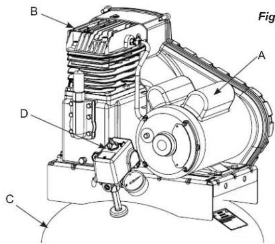
The basic components of the air compressor are the electric motor, pump, pressure switch and tank (see Fig. 1).
The electric motor (see A) powers the pump.
The pump (see B) compresses the air and discharges it into the tank.
The tank (see C) stores the compressed air.
The pressure switch (see D) shuts down the motor when the tank reaches a pre-set "cut-out" pressure. As compressed air is used and the tank drops to a pre-set "cut-in" pressure, the switch restarts the motor automatically, and the pump resumes compressing air.
ASSEMBLY
ASSEMBLING THE COMPRESSOR

This compressor was shipped with oil in the pump crankcase. Check oil before operating the air compressor, see Check Oil under Maintenance.
- Unpack the air compressor. Inspect the unit for damage. If the unit has been damaged in transit, contact the carrier and complete a damage claim. Do this immediately because there are time limitations to damage claims.
The carton should contain:
-
air compressor - operator/parts manual
-
Check the compressor's serial label to ensure that you have received the model ordered, and that it has the required pressure rating for its intended use.
- Locate the compressor according to the following guidelines:
a. For optimum performance, locate the compressor close to the power panel, as specified in ELECTRICAL POWER REQUIREMENTS, and as close as possible to the place where the air will be used. This ensures maximum power to the compressor and maximum air pressure to the tool. If both of these conditions cannot be met, it is better to locate the compressor close to the power panel, and use a longer air hose or distribution line to reach the usage area.
b. The flywheel side of the compressor must be at least 12 inches (31 cm) from any wall or obstruction, in a clean, well-ventilated area, to ensure sufficient air
flow and cooling.
c. In cold climates, locate the compressor in a heated building. This will reduce problems with lubrication, motor starting and freezing of water condensation.
d. Remove the compressor from the shipping pallet and place it on the floor or a hard, level surface. The compressor must be level to ensure proper lubrication of the pump and good drainage of the moisture in the tank.
CAUTION: The shipping pallet is not designed as a base for an operating compressor. Operating the compressor while it is on the pallet will void your warranty.
e. To prevent damage to tank and pump, the tank must be shimmed so the pump is level within 1/8" per lineal foot
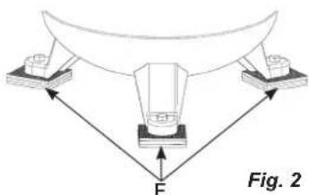
Fig. 2
- Connect an air hose or distribution line (not included) to the compressor.
TYPICAL INSTALLATION
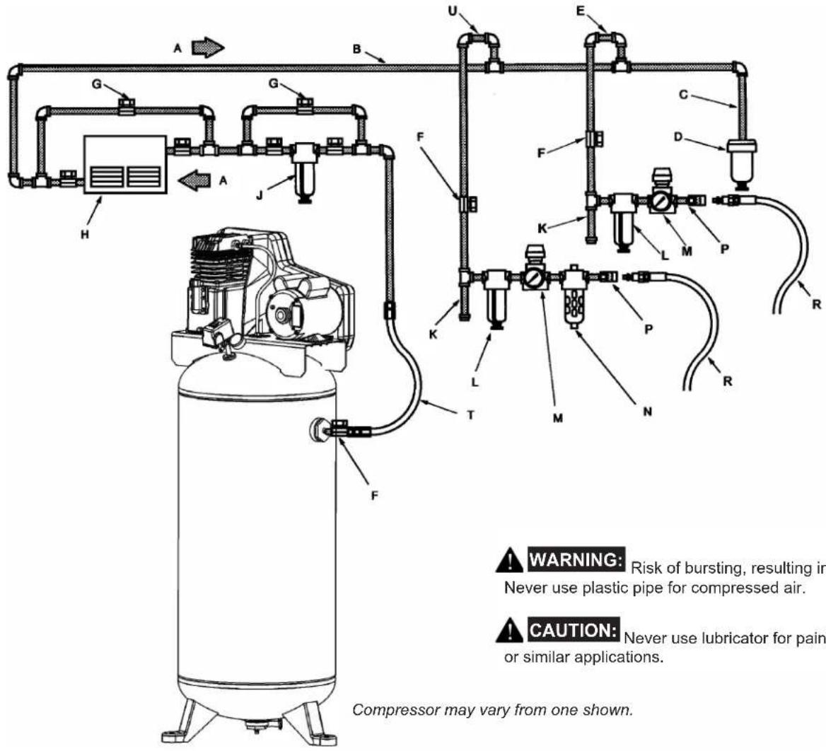
A Air flow
B Feeder line
C Drain leg
D Moisture trap with drain
E Non-lubricated supply line
F 1/4 turn valve
G Bypass
H Air dryer or aftercooler
J Line filter
K Drip tee with drain
L Air/water filter with petcock
M Regulator
N Lubricator
P Quick coupler
R Air hose to tool
T Flexible air line
U Lubricated supply line
Air dryers and after coolers
An air dryer or aftercooler is installed directly in the air line.
To remove this moisture, run the main air line downhill to a moisture trap and drain. Air/water filters should also be installed in the positions shown.
Air pressure regulation
The air pressure gauge on the pressure switch measures air pressure inside the tank, not pressure in the air line. Install an air regulator in the drop line for each tool, to regulate air pressure to that tool. Never exceed the maximum pressure rating of the tool.
Air lubrication
Install an air lubricator only for those tools requiring lubrication. Do not use a lubricator for paint spraying or similar applications. The oil will contaminate the paint and ruin the job.
Shut-off valves
Install shut-off valves in each drop line, to isolate the tool and its accessories for servicing. You can also install a bypass line around an accessory.
Moisture removal and air filtration
As the air cools, moisture will condense in the lines. This moisture must be removed before it reaches the tool being used.
COMPRESSOR CONTROLS
Main Power Disconnect
Install a main power disconnect switch in the power line to the compressor, near the compressor's location. It is operated manually, but when it is in the ON position, the compressor will start up or shut down automatically based on air demand. ALWAYS operate this switch to OFF when the compressor is not being used.
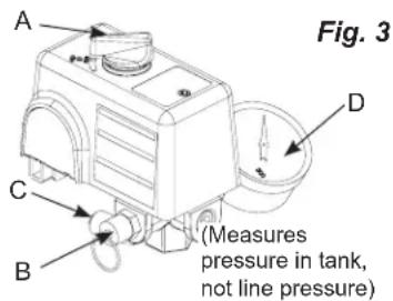
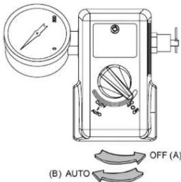
Pressure switch (see A)
This switch turns on the compressor. It is operated manually, but when in the ON position, it allows the compressor to start up or shut down automatically, without warning, upon air demand. ALWAYS set this switch to OFF when the compressor is not being used.
WARNING: For your safety, tank pressure is preset within the switch and must never be tampered with.
This switch must not be adjusted by the operator; doing so will void the warranty. The pressure switch controls the level of air pressure in the tank by automatically starting and stopping the motor, as required to maintain the factory preset pressure level.
The pressure switch also automatically bleeds pressure from the pump head when the pump stops. This feature eliminates back pressure in the pump, ensuring easier starting. Tank Safety Valve (see B)
Used to allow tank pressure to escape into the atmosphere. If the pressure switch does not shut off the compressor at its "cutout" pressure setting, the safety valve will protect against high
pressure by releasing tank pressure at its factory set pressure (slightly higher than the pressure switch "cut-out" setting). To operate manually, pull the ring on the valve to relieve air pressure in the tank.
Pressure Release Valve (see C)
The pressure release valve (located on the bottom of the pressure switch), is designed to release compressed air from the compressor head and outlet tube when the compressor reaches "cut-out" or is shut off. The pressure valve allows the motor to restart freely. When the motor stops running, air will be heard escaping from this valve for a few seconds. No air should be heard leaking when the motor is running or after brief release after reaching "cut-out" pressure.
Tank Pressure Gauge (see D)
This gauge measures the pressure level of the air stored in the tank. It is not adjustable by the operator, and does not indicate line pressure.
ELECTRICAL POWER REQUIREMENTS
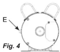
MOTOR RESET SWITCH
WARNING: Ensure that all guards and shrouds are in place before pressing the reset switch to restart the motor.
If the motor shuts down because of overload, wait 10-15 minutes so the motor can cool down, then press (NEVER force) the reset switch (see E) to restart the motor (see Fig.4).
ELECTRICAL WIRING
Refer to the air compressor's serial label for the unit's voltage and amperage requirements. Ensure that all wiring is done by a licensed electrician, in accordance with the National Electrical Code. Use electrical conduit to protect the wiring.
MAIN POWER PANEL
For best performance and reliable starting, the air compressor must be installed on a dedicated circuit, as close as possible to the electrical power panel. Provide circuit breaker or fuse protection at your main power panel. Use time delay fuses on the circuit, because the compressor will momentarily draw several times its specified amperage when first started.
MAIN POWER DISCONNECT SWITCH
Install a main power disconnect switch in the line from the panel to the compressor. The main power disconnect switch must be located near the compressor, for ease of use and safety. When turned OFF, the main power disconnect switch shuts off all
power to the compressor. When it is turned ON, the compressor will start and stop automatically, controlled by the pressure switch.
LOW VOLTAGE PROBLEMS
Low voltage will cause difficult starting or an overload. Low voltage can be caused by a low supply voltage from the local power company, other equipment running on the same line, or inadequate wiring. If any other electrical devices are drawing from the compressor's circuit, it may fail to start.
Low voltage to the compressor can be caused by a supply wire of insufficient gauge for the distance between the compressor and the power source. The longer the distance, the larger the wire gauge (lower the number) must be, to overcome the inherent voltage loss caused by the wire resistance. Refer to the National Electrical Code to determine proper wire size for your circuit.
If the wiring is not adequate, the input voltage will drop by 20 to 40 volts at startup. Low voltage or an overloaded circuit can result in sluggish starting that causes the circuit breaker to trip, especially in cold conditions.
GROUNDING INSTRUCTIONS
This product must be connected to a grounded, metallic, permanent wiring system, or an equipment - grounding terminal or lead on the product.
OPERATING INSTRUCTIONS
BREAK-IN OF THE PUMP
NOTE: The pump is shipped with break-in oil which should be changed after the first 8 hours of operation.
- Make sure the power is connected at the power panel.
- Check the oil level in the pump (see "Checking the Oil" in the maintenance section).
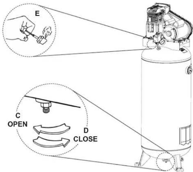
- Open the petcock (see C).

CAUTION: Escaping air and moisture can propel debris that may cause eye injury. Wear safety goggles when opening petcock.
- Turn ON the main power disconnect switch. Turn the pressure switch to the AUTO position (see B). The motor should start. Allow the compressor to run for 30 minutes, to break in the internal parts.
NOTE: After about 30 minutes, if the unit does not operate properly, SHUT DOWN IMMEDIATELY, and contact a qualified service center. DO NOT return the unit to the store where it was purchased. - After about 30 minutes, turn the pressure switch to the OFF position (see A).
- Shut OFF the main power disconnect.
- Close the petcock (see D). Turn in the clockwise direction.
- Turn ON the main power disconnect switch. Turn the pressure switch to the AUTO position. The compressor will start and fill the tank to the cut-out pressure and stop.
NOTE: As compressed air is used, the pressure switch will restart the motor automatically to supply more compressed air to the tank.
DAILY START-UP
- Check the oil level in the pump (see "Checking the Oil" in the maintenance section).
- Make sure the main power disconnect switch is shut OFF.
- Close the tank petcock (see D).
- Turn ON the main power disconnect switch. Turn the pressure switch to the AUTO position (see B). The pump will start filling the tank with air. When the air pressure in the tank reaches the level preset at the factory, the pressure switch will turn off the electric motor. As air is used and the pressure level in the tank drops, the pressure switch will start the motor and the pump will begin refilling the tank.

WARNING:
High temperatures are generated
by the pump. To prevent burns or other injuries, DO NOT touch the pump or transfer tube while the pump is running. Allow it to cool before handling or servicing. Keep children away from the compressor times.
NOTE: If the unit does not operate properly, SHUT DOWN IMMEDIATELY, and contact a qualified service center.
COLD WEATHER STARTING
In cold weather check that the air filters are clean.
NOTE: Use synthetic blend, non-detergent air compressor oil.
Open the petcock (C) to depressurize the tank to zero PSI before starting. If the compressor will not start, relocate it in a warmer location.
SHUTDOWN
- Turn the pressure switch to the OFF position (see A).
- Shut OFF the main power disconnect switch.
- Reduce pressure in the tank through the outlet hose. You can also pull the tank safety valve ring (see E) and keep it open to relieve pressure in the tank

CAUTION: Escaping air and moisture can propel debris that may cause eye injury. Wear safety goggles when opening petcock.
- Open the petcock (see C) to allow moisture to drain from the tank.
MAINTENANCE
MAINTENANCE

WARNING:
This unit starts automatically.
ALWAYS shut off the main power disconnect, and bleed all pressure from the system before servicing the compressor, and when the compressor is not in
use. Do not use the unit with the shrouds or belt guard removed. Serious injury could occur from contact with moving parts.
Regular maintenance will ensure trouble-free operation. Your electric powered air compressor represents high-quality engineering and construction; however, even high-quality machinery requires periodic maintenance. The items listed below should be inspected on a regular basis.
DRAINING THE TANK
Drain the moisture from the tank (for instructions, see "Shutdown" in the operating instructions section).

WARNING:
WARNING: Condensation will accumulate in the tank. To prevent corrosion of the tank from the inside, this moisture must be drained at the end of every workday. Wear protective eyewear.
CHECKING THE OIL
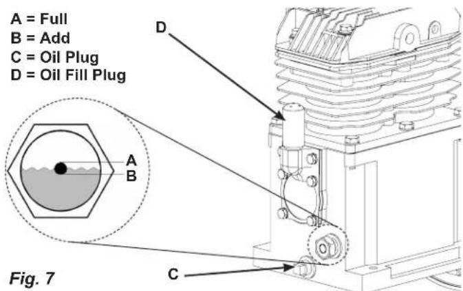
Check the level of oil in the pump with the sight glass. The pump oil level must be between A and B. Do not overfill or underfill.
NOTE: Use full synthetic, non-detergent air compressor oil.
CHANGING THE OIL
Remove the oil plug (C) and drain the oil until it slows to a drip, then close. Unscrew the oil fill plug (D) and add compressor oil (16 oz. (473ml) ) until it is between full (A) and add (B). Replace the oil fill plug. Never overfill or under fill the pump.
NOTE: Use full synthetic, non-detergent air compressor oil.
DRIVE BELT TENSION ADJUSTMENT
NOTE: Drive belt tensioning and pulley alignment are done at the same time. They are discussed separately for clarity.

WARNING:
This unit starts automatically.
ALWAYS shut off the main power disconnect, and bleed all pressure from the system before servicing the compressor, and when the compressor is not in
use. Do not use the unit with the shrouds or belt
guard removed. Serious injury could occur from contact with moving parts.
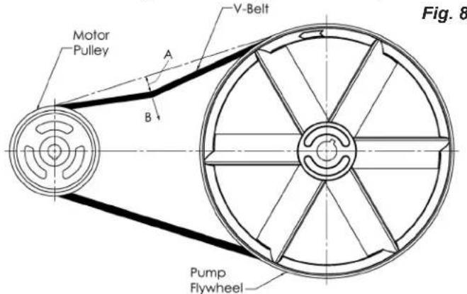
Proper belt tension and pulley alignment must be maintained for maximum drive efficiency and belt life. The correct tension exists if a deflection (see A) of 1 / 2 (13mm) occurs by placing 10 lbs. (4.6kg) of force see B) midway between the motor pulley and the pump flywheel (See Fig.8). This deflection can be adjusted by the following procedure. The pulley should be carefully aligned with the flywheel, and all setscrews should be kept tight.
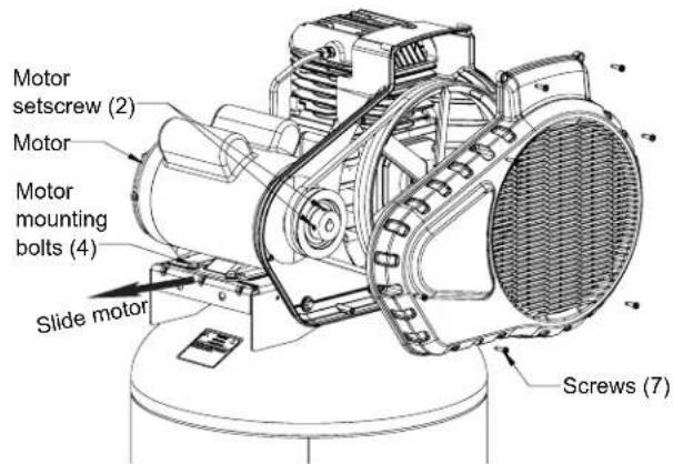
- Remove the front of the beltguard by removing the screws using a Torx T25 bit.
- Loosen the motor mounting bolts.
- Shift the motor to the point where the correct deflection exists (A & B).
- Retighten the motor mounting bolts to 130-180 in.-lbs.
- Check to ensure that the tension remained correct
- Reinstall the belt guard. All moving parts must be guarded.
PULLEY ALIGNMENT
NOTE: Drive belt tensioning and pulley alignment are done at the same time. They are discussed separately for clarity.

WARNING:
This unit starts automatically.
ALWAYS shut off the main power disconnect, and bleed all pressure from the system before servicing the compressor, and when the compressor is not in Do not use the unit with the shrouds or belt I removed. Serious injury could occur from act with moving parts.
MAINTENANCE
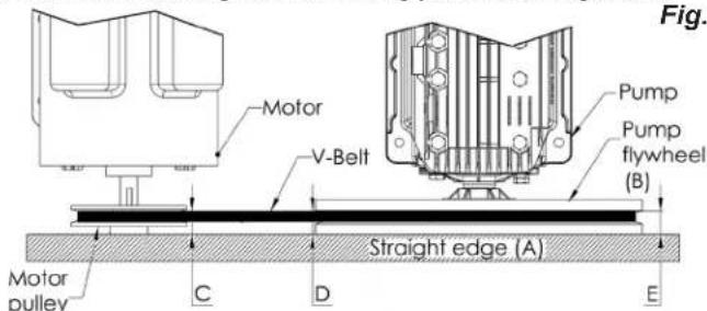
NOTE: Once the motor pulley has been moved from its factory set location, the grooves of the flywheel and pulley must be aligned to within 1/16 to prevent excessive belt wear.
To check pulley alignment, remove the belt guard and place a straightedge (see A) against the pump flywheel (see B) (See Fig. 9). Measure and record the distance from the straightedge to the edge of the drive belt at point C. Then measure the distance from the straightedge to the edge of the drive belt again at points D and E. Both distances should be the same as at point C. If D or E are different from C, there is a misalignment which must be corrected before the compressor is run. To correct a pulley misalignment, use the following procedure.
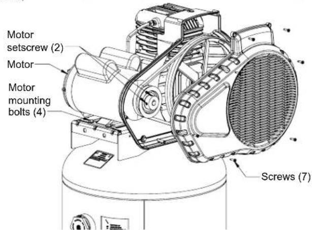
- Remove the front of the belt guard by removing the screws using a Torx T25 bit.
- Loosen the motor mounting bolts.
- Loosen the setscrews on the motor pulley.
- Align the motor pulley with the pump flywheel (C-D-E must be equal).
- Retighten the motor pulley setscrews.
- Adjust the proper belt tension.
- Retighten the motor mounting bolts to 130-180 in.-lbs.
- Reinstall the belt guard. All moving parts must be guarded.
DRIVE BELT REPLACEMENT
WARNING:
This unit starts automatically.
ALWAYS shut off the main power disconnect, and bleed all pressure from the system before servicing the compressor, and when the compressor is not in do not use the unit with the shrouds or belt removed. Serious injury could occur from act with moving parts.
- Remove the front of the belt guard by removing the screws using a Torx T25 bit.
-
Loosen the motor mounting bolts.
-
Shift the motor towards the pump to the point where the belt can be easily removed and installed.
- Remove and replace belt. NOTE: The belt must be centered over the grooves on the flywheel and motor pulley.
- Shift the motor back to the point where the correct deflection exists (see "Drive Belt Tension Adjustment").
- Retighten the motor mounting bolts to 130-180 in.-lbs.
- Check to ensure that the tension remained correct.
- Reinstall the belt guard. All moving parts must be guarded.
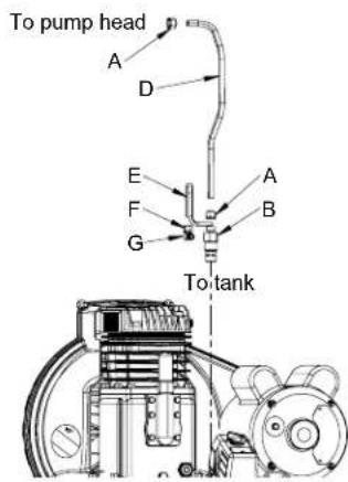
TO REPLACE OR CLEAN CHECK VALVE

WARNING:
This unit starts automatically.
ALWAYS shut off the main power disconnect, and bleed all pressure from the system before servicing the compressor, and when the compressor is not in Do not use the unit with the shrouds or belt I removed. Serious injury could occur from act with moving parts.
- Shut OFF the main power disconnect. Relieve all the air pressure from the tank (refer to "Shutdown" in Operating Instructions). Make sure the compressor has cooled down before servicing.
- Using the appropriately sized wrench, loosen the compression nuts (A) on the check valve
(B) and pump head
(C). Remove the transfer tube (D). - Using the appropriately sized wrench, loosen the compression nut (F) from the connector (G), located on the side of the check valve. Remove the bleeder tube (E).
- Making note of the orientation for reassembly, unscrew the check valve from the tank (counterclockwise) using the appropriately sized wrench.
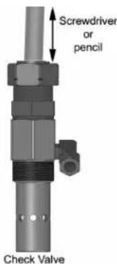
- Using a pencil or screwdriver, carefully push the valve disc up and down. If the valve disc does not move freely up and down, the check valve needs to be cleaned or replaced.
- Clean the check valve with warm soapy water and make sure to dry thoroughly before reinstalling. If the disc valve still does not move freely up and down, it will need to be replaced.
- Apply thread sealant to the check valve threads and reinstall into the tank by turning clockwise. Make sure it is the same orientation as when it was removed.
- Replace the bleeder tube and tighten compression nut.
MAINTENANCE
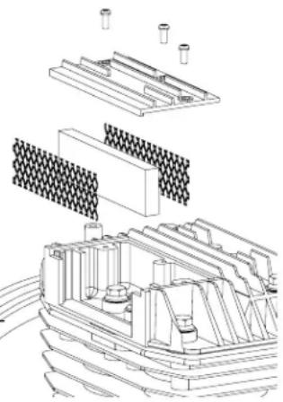
CLEANING THE AIR FILTERS
WARNING:
Hot surfaces. Risk of burn. Tubes,

pump head, and surrounding parts are very hot, do not touch. Allow compressor to cool prior to servicing.
A dirty air filter will not allow the compressor to operate at full capacity. Keep the air filter clean at all times.
- Ensure Auto/Off switch is in the OFF Position.
- Allow unit to cool.
- Remove the 3 phillips screws from the pump head.
- Remove the small plate, being careful not to drop anything on the exposed valves.
- Carefully lift out the air filter and screens. NOTE: The screen edges are sharp.
- Place cleaned or new air filter between the screens and ins
- Place the plate back onto the pump head, insert the screws, tighten the screws.
CAUTION:
Risk of unsafe operation. Do not operate
without air filter.
CHECKING THE RELIEF VALVE
Pull the tank safety valve daily to ensure that it is operating properly and to clear the valve of any possible obstructions.
TESTING FOR LEAKS
Check that all connections are tight. A small leak in any of the hoses, transfer tubes, or pipe connections will substantially reduce the performance of your air compressor. If you suspect a leak, spray a small amount of soapy water around the area of the suspected leak with a spray bottle. If bubbles appear, repair or replace the faulty component. Do not over tighten any connections.
STORAGE
Before storing the compressor for a prolonged period, use an air blow gun to clean all dust and debris from the compressor. Disconnect the power cord and coil it up. Pull the tank safety valve to release all pressure from the tank. Drain all moisture from the tank. Clean the filter elements and filter housings; replace the elements if necessary. Drain the oil from the pump crankcase and replace it with new oil. Cover the entire unit to protect it from moisture and dust.
SERVICE INTERVAL
| Perform the following maintenance at the intervals indicated below. | Daily or after each use | Monthly or Every 50 Hours | 1 Year or 200 Hours | After first 8 hours and then every 500 operating hours |
| Inspect air filters (clean or replace as necessary) | ● | |||
| Check pump oil level | ● | |||
| Change pump oil (Use full synthetic, non-detergent air compressor oil.) | ● | |||
| Operate the tank safety valve | ● | |||
| Check belt tension | ● | |||
| Drain tank | ● | |||
| Check and tighten all bolts (do not over tighten) | ● |
TROUBLESHOOTING
Note: Troubleshooting problems may have similar causes and solutions.
| PROBLEM | POSSIBLE CAUSE SOLUTION | |
| Excessive current draw trips circuit breaker or motor reset switch | Low voltage/motor overload Check Drive belt tension too tight Readjust belt tension. Restricted air passages Inspect and replace transfer tubes or the check valve, (see "To replace or clean check valve" in the maintenance section). | that power supply is adequate and that compressor is on a dedicated circuit. |
| Seized pump Contact a qualified service center. | ||
| Compressor stalls Low voltage | Air leaks | Tighten or replace leaking fittings or connections. Do not overtighten. |
| Leaking valves Contact a qualified service center. | ||
| Restricted air intake Clean or replace air filter element(s). | ||
| Blown gaskets Contact a qualified service center. | ||
| Worn piston rings or cylinder Contact a qualified service center. | ||
| Compressor pump knocking | Loose motor pulley or pump flywheel | Retighten pulley and flywheel. Check alignment. |
| Low oil level in pump crankcase Keep oil at proper level at all times. | ||
| Excess carbon on valves or top of piston | Contact a qualified service center. | |
| Oil in discharge air | Worn piston rings or cylinder | Contact a qualified service center. |
| Restricted air intake Clean or replace the air filter element(s). | ||
| Oil level too high | Reduce to proper level. | |
| Overheating | Poor ventilation | Relocate compressor to an area with cool, dry, well circulated air, at least 12 in. from nearest wall. |
| Dirty cooling surfaces | Clean all cooling surfaces thoroughly. | |
| Restricted air passages Inspect and replace transfer tubes or the check valve, (see "To replace or clean check valve" in the maintenance section). | ||
| Excessive belt wear | Pulleys out of alignment | Realign pulley with compressor flywheel. |
| Improper belt tension | Readjust. | |
| Pulleys wobbles | Replace the pulley and check for a damaged crankshaft or flywheel. | |
| Compressor won't start in cold temperatures | Too much back pressure in tank Open petcock when starting motor. | |
| 40W oil in crankcase | Use full synthetic, non-detergent air compressor oil. | |
| Compressor too cold | Move compressor to a warmer location. | |
| Air leaking through pleeder valve after compressor shuts off | Dirty or defective check valve. | Replace or clean the check valve (see "To replace or clean check valve" in the maintenance section). |
TABLE DES MATIÈRES
CONSIGNES DE SECURITÉ
| CONSIGNES DE SECURITÉ | 12-13 | SPECIFICATIONS DE L'ALIMENTATION |
| GLOSSÀIRE DES TERMES | 14 | ÉLECTRIQUES |
| VUE D'ENSEMBLE | 14 | MODE D'EMPLOI |
| ASSEMBLAGE | 14 | ENTRETIEN |
| INSTALLATION TYPIQUE | 15 | ENTRETIEN PÉRIODIQUE |
| COMMANDES DU COMPRESSEUR | 16 | DéPANNAGE |
El aire y la humedad queSEOSEOSEOSEOSEOSEOSEOSEOSEOSEOSEOSEOSEOSEOSEOSEOSEOSEOSEOSEOSEOSEOSEOSEOSEOSEOSEOSEOSEOSEOSEOSEOSEOSEOSEOSEOSEOSEOSEOSEOSEOSEOSEOSEOSEOSEOSEOSEOSEOSEOSEOSEOSEOSEOSEOSEOSEOSEOSEOSEOSEOSEOSEOSEOSEOSEOSEOSEOSEOSEOSEOSEOSEOSEOSEOSEOSEOSEOSEOSEOSEOSEOSEOSEOSEOSEOSEOSEOSEOSEOSEOSEOSEOSEOSEOSEOSEOSEOSEOSEO SEOEOEEOEOEOEOEOEOEOEOEOEOEOEOEOEOEOEOEOEOEOEOEOEOEOEOEOEOEOEOEOEOEOEOEOEOEOEOEOEOEOEOEOEOEOEOEOEOEOEOEOEOEOEOEOEOEOEOEOEOEOEOEOEOEOEOEOEOEOEOEOEOEOEOEOEOEOEOEOEOEOEOEOEOEOEOEOEOEOEOEOEOEOEOEOEOEOEOEOEOEOEOOO
Replacement parts and service are available from your nearest authorized Service Center. If the need arises, contact Product Service as listed at right.
When consulting with a Service Center or Product Service, refer to the model number and serial number located on the serial label of the compressor. Proof of purchase is required for all transactions and a copy of your sales receipt may be requested.
Record the model number, serial number, and date purchased in the spaces provided below. Retain your sales
Model No.
Serial No.
receipt and this manual for future reference.
When needing service, please contact the nearest authorized Service Center or call:
PRODUCT SERVICE
In U.S.A. or Canada
Toll-Free
Fax
1-888-895-4549
1-507-723-5013
Date Purchased, la date d'achat, la fecha de compra
PIECES ET RÉPARATIONS
Sanborn Mfg., Division of MAT Industries, LLC.
118 West Rock Street
Made in the USA of domestic and global components.
©2019 - 2020 Sanborn Mfg.
A Division of MAT Industries, LLC.
Springfield, MN 56087
1-888-895-4549
www.matoemparts.com