CX6500E - Generator Powermate - Free user manual and instructions
Find the device manual for free CX6500E Powermate in PDF.


| Product Type | Portable Generator |
| Brand | Powermate |
| Model | CX6500E |
| Rated Power (AC) | 6,500 watts (120/240 V) |
| Starting Power | 8,125 watts |
| Rated AC Voltage | 120/240 V |
| Frequency | 60 Hz |
| Phase | Single Phase |
| Appliance Weight | 91.6 kg (202 lb) |
| Fuel Tank Capacity | 26.5 liters (7 US gallons) |
| Fuel Type | Unleaded gasoline (87 octane min., up to 10% ethanol) |
| Engine Oil Capacity | 1.1 liter (1.1 quart) |
| Recommended Oil Type | SAE 30 (summer), 10W-30 (all season), 5W-30 synthetic (winter) |
| Engine Displacement | 420 cc |
| Starting Type | Manual (recoil starter) and Electric (battery) |
| Power Outlets | 1x double 120V 20A (GFCI), 1x twist-lock NEMA L14-30R 120/240V 30A |
| Circuit Breakers | Toggle circuit breakers on outlets |
| Runtime at Half Load | 9.75 hours |
| Low Oil Shutdown System | Yes, built-in sensor |
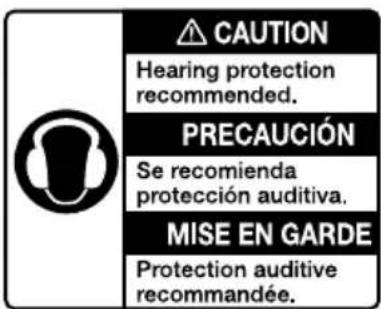
| Sound Level | Hearing protection recommended |
| Warranty | Consult manual for details |
Frequently Asked Questions - CX6500E Powermate
User questions about CX6500E Powermate
0 question about this device. Answer the ones you know or ask your own.
Ask a new question about this device
Download the instructions for your Generator in PDF format for free! Find your manual CX6500E - Powermate and take your electronic device back in hand. On this page are published all the documents necessary for the use of your device. CX6500E by Powermate.
USER MANUAL CX6500E Powermate
natural_image
Technical line drawing of a portable gas generator with wheels and control panel (no text or symbols)MODEL:
SERIAL:
DATE PURCHASED:

WARNING
This product is not intended to be used in a critical life support application. Failure to adhere to this warning could result in death or serious injury. (000209a)
Register your Powermate product at:
www.powermate.com
1-800-445-1805
Section 1 Introduction and Safety 1
Introduction 1
Safety Rules 1
Safety Symbols and Meanings ..... 1
Exhaust and Location Hazards ..... 2
Electrical Hazards 3
Fire Hazards 3
Standards Index 3
Section 2 General Information and
Setup 4
Know Your Generator 5
Emissions 5
Connection Plugs 6
Remove Contents from Carton ..... 6
Assembly 7
Battery Cable Connection (electric start only) 8
Add Engine Oil 8
Fuel 9
Section 3 Operation .... 10
Operation and Use Questions ..... 10
Before Starting Engine 10
Prepare Generator for Use ...... 10
Grounding the Generator When In Use 10
Know Generator Limits 11
Transporting/Tipping of the Unit .... 11
Starting Pull Start Engines 12
Starting Electric Start Engines ..... 12
Generator Shut Down 12
Low Oil Level Shutdown System ... 12
Section 4 Maintenance and
Troubleshooting ....13
Maintenance 13
Maintenance Schedule 13
Preventive Maintenance ....13
Engine Maintenance ....13
Battery Replacement (if applicable) 15
Inspect Muffler and Spark Arrester 15
Valve Clearance 16
Storage 16
Troubleshooting 17
Notes 19
WARNING
California Proposition 65. Engine exhaust and some of its constituents are known to the state of California to cause cancer, birth defects, and other reproductive harm. (00004)
(000004)
WARNING
California Proposition 65. This product contains or emits chemicals known to the state of California to cause cancer, birth defects, and other reproductive harm. (000005)
Section 1 Introduction and Safety
Introduction
Thank you for purchasing a Powermate product. This unit has been designed to provide high-performance, efficient operation, and years of use when maintained properly.

WARNING
Consult Manual. Read and understand manual completely before using product. Failure to completely understand manual and product could result in death or serious injury. (000100a)
If any section of the manual is not understood, contact your nearest Independent Authorized Service Dealer (IASD), or contact Powermate Customer Service at 1-800-445-1805, or www.powermate.com with any questions or concerns.
The owner is responsible for proper maintenance and safe use of the equipment. Before operating, servicing or storing this generator:
- Study all warnings in this manual and on the product carefully.
- Become familiar with this manual and the unit before use.
- Refer to the Assembly section of the manual for instructions on final assembly procedures. Follow the instructions completely.
Save these instructions for future reference. ALWAYS supply this manual to any individual that will use this machine.
THE INFORMATION CONTAINED HEREIN WAS BASED ON MACHINES IN PRODUCTION AT THE TIME OF PUBLICATION. POWERMATE RESERVES THE RIGHT TO MODIFY THIS MANUAL AT ANY TIME.
Safety Rules
The manufacturer cannot anticipate every possible circumstance that might involve a hazard. The warnings in this manual, and on tags and decals affixed to the unit are, therefore, not all inclusive. If using a procedure, work method or operating technique that the manufacturer does not specifically recommend, verify that it is safe for others. Also make sure the procedure, work method or operating technique utilized does not render the equipment unsafe.
Throughout this publication, and on tags and decals affixed to the generator, DANGER, WARNING, CAUTION and NOTE blocks are used to alert personnel to special instructions about a particular operation that may be hazardous if performed incorrectly or carelessly. Observe them carefully. Their definitions are as follows:
DANGER
Indicates a hazardous situation which, if not avoided, will result in death or serious injury.
(000001)
WARNING
Indicates a hazardous situation which, if not avoided, could result in death or serious injury.
(000002)
CAUTION
Indicates a hazardous situation which, if not avoided, could result in minor or moderate injury.
(000003)
NOTE: Notes contain additional information important to a procedure and will be found within the regular text of this manual.
These safety warnings cannot eliminate the hazards that they indicate. Common sense and strict compliance with the special instructions while performing the action or service are essential to preventing accidents.
Safety Symbols and Meanings
DANGER
Using a generator indoors CAN KILL YOU IN MINUTES. Generator exhaust contains carbon monoxide. This is a poison you cannot see or smell.

NEVER use inside a home or garage, EVEN IF doors and windows are open.

Only use OUTSIDE and far away from windows, doors, and vents.
000657

DANGER
Asphyxiation. Running engines produce carbon monoxide, a colorless, odorless, poisonous gas.
Carbon monoxide, if not avoided, will result in death or serious injury. (000103)
- If you start to feel sick, dizzy, or weak after the generator has been running, move to fresh air IMMEDIATELY. See a doctor, as you could have carbon monoxide poisoning.

DANGER
The exhaust system must be properly maintained. Do not alter or modify the exhaust system as to render it unsafe or make it noncompliant with local codes and/or standards. Failure to do so will result in death or serious injury. (000179a)

DANGER
Electrocution. Water contact with a power source, if not avoided, will result in death or serious injury.
(000104)

DANGER
Electrocution. Turn utility and emergency power supplies to OFF before connecting power source and load lines. Failure to do so will result in death or serious injury. (000116)
WARNING
Equipment and property damage. Do not alter construction of, installation, or block ventilation for generator. Failure to do so could result in unsafe operation or damage to the generator. (000146)

WARNING
Asphyxiation. Always use a battery operated carbon monoxide alarm indoors and installed according to the manufacturer's instructions. Failure to do so could result in death or serious injury. (000178a)
!WARNING
Equipment and property damage. Do not operate unit on uneven surfaces, or areas of excessive moisture, dirt, dust or corrosive vapors. Doing so could result in death, serious injury, property and equipment damage. (000250)

WARNING
Moving Parts. Keep clothing, hair, and appendages away from moving parts. Failure to do so could result in death or serious injury. (000111)

WARNING
Hot Surfaces. When operating machine, do not touch hot surfaces. Keep machine away from combustables during use. Hot surfaces could result in severe burns or fire. (000108)
WARNING
Do not insert any object through the air cooling slots. Generator can start at any time and could result in death, serious injury, and unit damage. (000142)
WARNING
Risk of injury. Do not operate or service this machine if not fully alert. Fatigue can impair the ability to service this equipment and could result in death or serious injury. (000215)
WARNING
Injury and equipment damage. Do not use generator as a step. Doing so could result in falling, damaged parts, unsafe equipment operation, and could result in death or serious injury. (000216)
WARNING
Equipment damage. Do not attempt to start or operate a unit in need of repair or scheduled maintenance. Doing so could result in serious injury, death, or equipment failure or damage. (000291)
000406
- For safety reasons, it is recommended that the maintenance of this equipment be performed by an IASD. Inspect the generator regularly, and contact the nearest IASD for parts needing repair or replacement.
Exhaust and Location Hazards

DANGER
Asphyxiation. Running engines produce carbon monoxide, a colorless, odorless, poisonous gas. Carbon monoxide, if not avoided, will result in death or serious injury. (000103)

DANGER
The exhaust system must be properly maintained. Do not alter or modify the exhaust system as to render it unsafe or make it noncompliant with local codes and/or standards. Failure to do so will result in death or serious injury. (000179a)
WARNING
Equipment and property damage. Do not alter construction of, installation, or block ventilation for generator. Failure to do so could result in unsafe operation or damage to the generator. (000146)

WARNING
Asphyxiation. Always use a battery operated carbon monoxide alarm indoors and installed according to the manufacturer's instructions. Failure to do so could result in death or serious injury. (000178a)
- If you start to feel sick, dizzy, or weak after the generator has been running, move to fresh air IMMEDIATELY. See a doctor, as you could have carbon monoxide poisoning.
Electrical Hazards

DANGER
Electrocution. Contact with bare wires, terminals, and connections while generator is running will result in death or serious injury. (000144)

DANGER
Electrocution. Water contact with a power source, if not avoided, will result in death or serious injury. (000104)

DANGER
Electrocution. In the event of electrical accident, immediately shut power OFF. Use non-conductive implements to free victim from live conductor. Apply first aid and get medical help. Failure to do so will result in death or serious injury. (000145)
WARNING
Accidental Start-up. Disconnect the negative battery cable, then the positive battery cable when working on unit. Failure to do so could result in death or serious injury. (000130)
- The National Electric Code (NEC) requires the frame and external electrically conductive parts of the generator be properly connected to an approved earth ground. Local electrical codes may also require proper grounding of the generator. Consult with a local electrician for grounding requirements in the area.
- Use a ground fault circuit interrupter in any damp or highly conductive area (such as metal decking or steel work).
Fire Hazards

ADANGER
Explosion and Fire. Fuel and vapors are extremely flammable and explosive. Add fuel in a well ventilated area. Keep fire and spark away. Failure to do so will result in death or serious injury.(000105)

DANGER
Do not overfill fuel tank. Fill to 1/2 in. of top of tank to allow for fuel expansion. Overfilling may cause fuel to spill onto engine causing fire or explosion, which will result in death or serious injury. (000166)
WARNING
Do not insert any object through the air cooling slots. Generator can start at any time and could result in death, serious injury, and unit damage. (000142)

WARNING
Fire risk. Fuel and vapors are extremely flammable. Do not operate indoors. Doing so could result in death, serious injury, or property or equipment damage. (000281)

WARNING
Explosion and fire risk. Do not smoke near unit. Keep fire and spark away. Failure to do so could result in death, serious injury, or property or equipment damage. (000282)

WARNING
Explosion and fire risk. Do not smoke while refueling unit. Failure to do so could result in death, serious injury, or property or equipment damage. (000284)
- Wipe up any fuel or oil spills immediately. Verify that no combustible materials are left on or near the generator. Keep the area surrounding the generator clean and free from debris and keep a clearance of five (5) feet on all sides to allow for proper ventilation of the generator.
- Do not operate the generator if connected electrical devices overheat, if electrical output is lost, if engine or generator sparks or if flames or smoke are observed while unit is running.
- Keep a fire extinguisher near the generator at all times.
Standards Index
- National Fire Protection Association (NFPA) 70: The NATIONAL ELECTRIC CODE (NEC) available from www.nfpa.org
- National Fire Protection Association (NFPA) 5000: BUILDING CONSTRUCTION AND SAFETY CODE available from www.nfpa.org
- International Building Code available from www.iccsafe.org
- Agricultural Wiring Handbook available from www.rerc.org, Rural Electricity Resource Council P.O. Box 309 Wilmington, OH 45177-0309
- ASAE EP-364.2 Installation and Maintenance of Farm Standby Electric Power available from www.asabe.org, American Society of Agricultural & Biological Engineers 2950 Niles Road, St. Joseph, MI 49085
This list is not all inclusive. Check with the Authority Having Jurisdiction (AHJ) for any local codes or standards which may be applicable to your jurisdiction.
Section 2 General Information and Setup
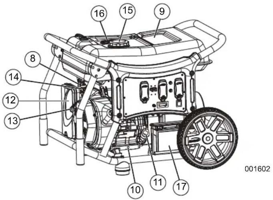
Figure 2-1. Features and Controls
TABLE 1. Generator Components
1 120 Volt AC, 20 Amp GFCI Duplex Receptacle
2 120 Volt AC, 30 Amp Locking
Receptacle (NEMA L5-30) (CX8000E only)
3 120/240 Volt AC, 30 Amp Locking Receptacle (NEMA L14-30R)
4 Circuit Breakers (AC)
5 Off/On/Start Switch
6 Hour Meter
7 Ground Terminal
8 Choke Lever
9 Fuel Tank
10 Oil Drain
11 Oil Fill
12 Air Cleaner
13 Recoil Handle
14 Fuel Shutoff Valve
15 Fuel Cap
16 Fuel Gauge
17 Battery

Figure 2-2. CX6500E Control Panel

Figure 2-3. CX8000E Control Panel
Know Your Generator

WARNING
Consult Manual. Read and understand manual completely before using product. Failure to completely understand manual and product could result in death or serious injury. (000100a)
Replacement owner's manuals are available at www.powermate.com.
Emissions
The United States Environmental Protection Agency (US EPA) (and California Air Resources Board (CARB), for engines/equipment certified to California standards) requires that this engine/equipment complies with exhaust and evaporative emissions standards. Locate the emissions compliance decal on the engine to determine applicable standards. For emissions warranty information, please reference the included emissions warranty. It is important to follow the maintenance specifications in the manual to ensure that the engine complies with the applicable emissions standards for the duration of the product's life.
TABLE 2. Product Specifications
| 6.5 kW / 8.0 kW Generator Specifications | |
| Rated Power 6500 Watt** / 8000 Watt** | |
| Surge Power 8125 Watt** / 10000 Watt** | |
| Rated AC Voltage (6.5 and 8.0 kW) 120/240 | |
| Rated AC Load6.5 kW8.0 kW | 54.2 / 27.1 Amps**66.6 / 33.3 Amps** |
| Rated Frequency 60 Hz @ 3600 RPM | |
| Phase Single Phase | |
| Unit Weight6.5 kW8.0 kW | 202 lbs. (91.6 kg)219 lbs. (99.2 kg) |
| ** Operating Temperature Range: -18 deg. C (0 deg. F) to 40 Deg. C (104 Deg. F). When operated above 25 deg. C (77 deg. F) there may be a decrease in power.** Maximum wattage and current are subject to, and limited by, such factors as fuel Btu content, ambient temperature, altitude, engine condition, etc. Maximum power decreases about 3.5% for each 1,000 feet above sea level; and will also decrease about 1% for each 6°C (10°F) above 16°C (60°F) ambient temperature. | |
| 6.5 kW / 8.0 kW Engine Specifications | |
| Displacement 420 cc / 445 cc | |
| Spark Plug Part No. 0J00620106 | |
| Spark Plug Type F7TC or Equivalent | |
| Spark Plug Gap 0.028-0.031 inch or (0.7-0.8 mm) | |
| Gasoline Capacity 26.5 L (7.0 U.S. gallons) | |
| Oil Type | See chart in Add Engine Oil. |
| Oil Capacity 1.1 L (1.1 qt.) | |
| Run Time at 50% Load 9.75 Hours / 9.4 Hours | |
| * Go to www.powermate.com or contact an IASD for replacement parts. | |
Connection Plugs
120 VAC, 20 Amp, GFCI Duplex Receptacle
The 120 Volt outlet is overload protected by a 20 Amp push-to-reset circuit breaker. See Figure 2-4. Each receptacle will power 120 Volt AC, single phase, 60 Hz electrical loads requiring up to 2400 watts (2.4 kW) or 20 Amps of current. Use only high quality, well-insulated, 3-wire grounded cord sets rated for 125 Volts at 20 Amps (or greater).
NOTE: Limit length of extension cords to fifteen feet, or less, to prevent voltage drop and overheating of wires.

natural_image
Pure electrical circuit lines without any symbols000203
Figure 2-4. 120 VAC, 20 Amp, GFCI Duplex Receptacle NEMA 5-20R
120/240 VAC, 30 Amp Receptacle
Use a NEMA L14-30 plug with this receptacle (rotate to lock/unlock). Connect a suitable 4-wire grounded cord set to plug and desired load. The cord set should be rated 250 Volts AC at 30 Amps (or greater). See Figure 2-5.
- CX6500E: Use this receptacle to operate 120 Volt AC, 60 Hz, single phase loads requiring up to 3240 Watts (3.2 kW) of power at 27 Amps or 240 Volt AC, 60 Hz, single phase loads requiring up to 6480 watts (6.4 kW) of power at 27 Amps. The outlet is protected by two 27 Amp 2-pole connected toggle circuit breakers.
- CX8000E: Use this receptacle to operate 120 Volt AC, 60 Hz, single phase loads requiring up to 3600 watts (3.6 kW) of power at 30 Amps or 240 Volt AC, 60 Hz, single phase loads requiring up to 7200 watts (7.2 kW) of power at 30 Amps. The outlet is protected by two 30 Amp push-to-reset circuit breakers.

natural_image
Circular diagram with four black curved segments arranged in a cross pattern (no text or symbols)000204
Figure 2-5. 120/240 VAC, 30 Amp Receptacle NEMA L14-30R
120 VAC, 30 Amp Receptacle
Use a NEMA L5-30 plug with this receptacle (rotate to lock/unlock). Connect a suitable 3-wire cord set to the plug and to desired load. The cord set should be rated for 125 Volts AC at 30 Amps (or greater). See Figure 2-6.
Use this receptacle to operate 120 Volt AC, 60Hz, single phase loads requiring up to 3600 watts (3.6kW) of power at 30 Amps. The outlet is protected by a 30 Amp push-to-reset circuit breaker.

natural_image
Circular diagram with three curved black segments, no text or symbols present000844
Figure 2-6. 120 VAC, 30 Amp Receptacle
NEMA L5-30
Remove Contents from Carton
- Open carton completely by cutting each corner from top to bottom.
- Remove and verify carton contents prior to assembly. Carton contents should contain the following:
TABLE 3. Accessories
| Item Qty. | |
| Main Unit 1 | |
| Owner's Manual 1 | |
| Liter SAE Oil 1 | |
| Oil Funnel 1 | |
| Wheel (1) 2 | |
| Handle (2) 2 | |
| Hardware Bag Qty. | |
| Axle Pin (3) | 2 |
| Foot Spacer (4) | 2 |
| Rubber Feet (5) | 2 |
| M12 x 4mm Flat Washer (6) | 2 |
| M12 x 1.5mm Flat Washer (7) | 2 |
| M8 Flat Washer (8) | 2 |
| M8 x 50 Bolt (9) | 2 |
| M8 x 80 Bolt (10) | 2 |
| M8 Nyloc Nut (11) | 4 |
| Cotter Pin (12) | 2 |
| Handle Grip (13) | 2 |
| Tool Kit Qty. | |
| 5mm Hex Key | 1 |
| 10 x 13mm Wrench | 1 |
| Spark Plug Wrench with Rod | 1 |
- Call Powermate Customer Service at 1-800-445-1805 with the unit model and serial number for any missing carton contents.
- Record model, serial number, and date of purchase on front cover of this manual.
Assembly

WARNING
Consult Manual. Read and understand manual completely before using product. Failure to completely understand manual and product could result in death or serious injury. (000100a)
Call Powermate Customer Service at 1-800-445-1805 for any assembly issues or concerns. Please have model and serial number available.
The following tools are required to install the accessory kit.
• See Table 3: Accessories (Tool Kit)
NOTE: The wheels are not intended for over-the-road use.
See Figure 2-7.
Install wheels as follows:
- Slide axle pin (3) through wheel (1), M12 x 4mm flat washer (6), and frame.
- Install M12 x 1.5mm flat washer (7) and insert cotter pin (12) through axle (4). Bend tabs (of cotter pins) outward to lock into place.
Install frame foot assembly as follows:
-
Slide M8 flat washer (8), rubber foot (5), foot spacer (4) onto M8 x 80 bolt (10).
-
Align through holes in frame rail and secure with M8 nyloc nut (11).
Install handle as follows:
- Slide M8 x 50 bolt (9) through handle bracket and handle (2). Secure with M8 nyloc nut (11).

Figure 2-7. Wheel, Handle and Foot Assembly
Battery Cable Connection (electric start only)

CAUTION
Do not make battery connections in reverse. Doing so will result in equipment damage.
(000167)
The unit has been shipped with the battery cables disconnected.
You will need two 8mm box wrenches to connect the battery cables. See Figure 4-5.
-
Cut off cable ties securing battery cables and remove red cover from battery terminal.
-
First, connect the red cable to the positive (+) battery terminal with the bolt and nut supplied.
-
Make sure connections are secure and slide rubber boot over the positive (+) battery terminal and connection hardware.
-
Connect the black cable to the negative (-) battery terminal with the bolt and nut supplied. Slide rubber boot over the negative (-) battery terminal and connection hardware.
-
Make sure all connections are secure.
NOTE: If the battery is unable to start the engine, charge it with an appropriate 12V charger or manually start the generator and let run until charged.
Add Engine Oil
CAUTION
Engine damage. Verify proper type and quantity of engine oil prior to starting engine. Failure to do so could result in engine damage.
(000135)
-
Place generator on a level surface.
-
Verify oil fill area is clean.
-
Remove oil fill cap and wipe dipstick clean. See Figure 2-8.

natural_image
Illustration of a mechanical tool with a rotating arrow and component, no text or symbols present000115
Figure 2-8. Remove Dipstick
- Add recommended engine oil. Climate determines proper engine oil viscosity. See chart to select correct viscosity.
NOTE: Use petroleum based oil (supplied) for engine break-in before using synthetic oil.

000399
NOTE: Some units have more than one oil fill location. It is only necessary to use one oil fill point.
- Thread dipstick into oil filler neck. Oil level is checked with dipstick fully installed.
- See Figure 2-9. Remove dipstick and verify oil level is within safe operating range.

natural_image
Technical line drawing of a mechanical component with threaded end and textured base (no text or symbols)000116
Figure 2-9. Safe Operating Range
- Install oil fill cap/dipstick and hand-tighten.
Fuel

DANGER
Explosion and Fire. Fuel and vapors are extremely flammable and explosive. Add fuel in a well ventilated area. Keep fire and spark away. Failure to do so will result in death or serious injury. (000105)

DANGER
Do not overfill fuel tank. Fill to 1/2 in. of top of tank to allow for fuel expansion. Overfilling may cause fuel to spill onto engine causing fire or explosion, which will result in death or serious injury. (000166)
(000166)
Fuel requirements are as follows:
- Clean, fresh, unleaded gasoline.
• Minimum rating of 87 octane/87 AKI (91 RON). - Up to 10% ethanol (gasohol) is acceptable (where available; non-ethanol-premium fuel is recommended).
• DO NOT use E85.
• DO NOT use a gas oil mix. -
DO NOT modify engine to run on alternate fuels. Stabilize fuel prior to storage.
-
Verify unit is OFF and cooled for a minimum of two minutes prior to fueling.
- Place unit on level ground in a well ventilated area.
- Clean area around fuel cap and remove cap slowly.
- Slowly add recommended fuel. Do not fill above red fuel indicator (A). See Figure 2-10.
- Install fuel cap.

000206
Figure 2-10. Add Recommended Fuel
NOTE: Allow spilled fuel to evaporate before starting unit.
IMPORTANT NOTE: It is important to prevent gum deposits from forming in fuel system parts such as the carburetor, fuel hose or tank during storage. Alcohol-blended fuels (called gasohol, ethanol or methanol) can attract moisture, which leads to separation and formation of acids during storage. Acidic gas can damage the fuel system of an engine while in storage. To avoid engine problems, the fuel system should be emptied before storage of 30 days or longer. See the Storage section. Never use engine or carburetor cleaner products in the fuel tank as permanent damage may occur.
Section 3 Operation
Operation and Use Questions
Call Powermate Customer Service at 1-800-445-1805 with questions or concerns about equipment operation and maintenance.
Before Starting Engine
- Verify engine oil level is correct.
- Verify fuel level is correct.
- Verify unit is secure on level ground, with proper clearance and is in a well ventilated area.
Prepare Generator for Use

DANGER
Asphyxiation. Running engines produce carbon monoxide, a colorless, odorless, poisonous gas. Carbon monoxide, if not avoided, will result in death or serious injury. (000103)

DANGER
The exhaust system must be properly maintained. Do not alter or modify the exhaust system as to render it unsafe or make it noncompliant with local codes and/or standards. Failure to do so will result in death or serious injury. (000179a)

WARNING
Risk of fire. Do not use generator without spark arrestor installed. Failure to do so could result in death or serious injury. (000118a)

WARNING
Asphyxiation. Always use a battery operated carbon monoxide alarm indoors and installed according to the manufacturer's instructions. Failure to do so could result in death or serious injury. (000178a)

WARNING
Risk of Fire. Hot surfaces could ignite combustibles, resulting in fire. Fire could result in death or serious injury. (000110)

WARNING
Hot Surfaces. When operating machine, do not touch hot surfaces. Keep machine away from combustibles during use. Hot surfaces could result in severe burns or fire. (000108)
CAUTION
Equipment and property damage. Disconnect electrical loads prior to starting or stopping unit. Failure to do so could result in equipment and property damage. (000136)
Grounding the Generator When In Use
The generator is equipped with a terminal for the connection of a grounding electrode system. NEC Article 250.34 (A) does not require the frame of the generator to be connected to a grounding electrode system when the generator only supplies power to cord and plug connected equipment through the receptacles on the generator.
When the generator supplies power to a 3 pole manual transfer switch or distribution panel boards for temporary power, a grounding electrode system shall be installed and connected to the grounding electrode terminal on the generator. See NEC 250.30, 250.34 and 250.52 for clarification. See Figure 3-1.
• Neutral Bonded to Frame

Figure 3-1. Grounding the Generator
Special Requirements
Review all Federal or State Occupational Safety and Health Administration (OSHA) regulations, local codes, or ordinances that apply to the intended use of the generator.
Consult a qualified electrician, electrical inspector, or the local agency having jurisdiction:
• In some areas, generators are required to be registered with local utility companies.
- If the generator is used at a construction site, there may be additional regulations which must be observed.
Connecting the Generator to a Building Electrical System
When connecting directly to a building electrical system, it is recommended that a manual transfer switch be used. Connections for a portable generator to a building electrical system must be made by a qualified electrician and in strict compliance with all national and local electrical codes and laws.
Know Generator Limits
Overloading a generator can result in damage to the generator and connected electrical devices. Observe the following to prevent overload:
- Add up the total wattage of all electrical devices to be connected at one time. This total should NOT be greater than the generator's wattage capacity.
- The rated wattage of lights can be taken from light bulbs. The rated wattage of tools, appliances, and motors can be found on a data label or decal affixed to the device.
- If the appliance, tool, or motor does not give wattage, multiply volts times ampere rating to determine watts (volts x amps = watts).
- Some electric motors, such as induction types, require about three times more watts of power for starting than for running. This surge of power lasts only a few seconds when starting such motors. Make sure to allow for high starting wattage when selecting electrical devices to connect to the generator:
- Figure the watts needed to start the largest motor.
- Add to that figure the running watts of all other connected loads.
The Wattage Reference Guide is provided to assist in determining how many items the generator can operate at one time.
NOTE: All figures are approximate. See data label on appliance for wattage requirements.
Table 3. Wattage Reference Guide
| Device Running | Watts |
| *Air Conditioner (12,000 Btu) 1700 | |
| *Air Conditioner (24,000 Btu) 3800 | |
| *Air Conditioner (40,000 Btu) 6000 | |
| Battery Charger (20 Amp) 500 | |
| Belt Sander (3") 1000 | |
| Chain Saw 1200 | |
| Circular Saw (6-1/2") 800 to 1000 | |
| *Clothes Dryer (Electric) 5750 | |
| *Clothes Dryer (Gas) 700 | |
| *Clothes Washer 1150 | |
| Coffee Maker | 1750 |
| *Compressor (1 HP) 2000 | |
| *Compressor (3/4 HP) | 1800 |
| *Compressor (1/2 HP) | 1400 |
| Curling Iron | 700 |
| *Dehumidifier | 650 |
| Disc Sander (9") | 1200 |
| Edge Trimmer | 500 |
| Electric Blanket | 400 |
| Electric Nail Gun 1200 | |
| Electric Range (per element) | 1500 |
| Electric Skillet | 1250 |
| *Freezer | 700 |
| *Furnace Fan (3/5 HP) | 875 |
| *Garage Door Opener | 500 to 750 |
| Hair Dryer 1200 | |
| Hand Drill | 250 to 1100 |
| Hedge Trimmer | 450 |
| Impact Wrench | 500 |
| Iron | 1200 |
| *Jet Pump | 800 |
| Lawn Mower | 1200 |
| Light Bulb | 100 |
| Microwave Oven 700 to 1000 | |
| *Milk Cooler | 1100 |
| Oil Burner on Furnace | 300 |
| Oil Fired Space Heater (140,000 Btu) | 400 |
| Oil Fired Space Heater (85,000 Btu) | 225 |
| Oil Fired Space Heater (30,000 Btu) | 150 |
| *Paint Sprayer, Airless (1/3 HP) | 600 |
| Paint Sprayer, Airless (hand-held) | 150 |
| Radio | 50 to 200 |
| *Refrigerator | 700 |
| Slow Cooker | 200 |
| *Submersible Pump (1-1/2 HP) | 2800 |
| *Submersible Pump (1 HP) | 2000 |
| *Submersible Pump (1/2 HP) | 1500 |
| *Sump Pump 800 to 1050 | |
| *Table Saw (10") | 1750 to 2000 |
| Television | 200 to 500 |
| Toaster | 1000 to 1650 |
| Weed Trimmer | 500 |
| * Allow 3 times the listed watts for starting these devices. | |
Transporting/Tipping of the Unit
Do not store or transport the unit at an angle greater than 15 degrees.
Starting Pull Start Engines

WARNING
Recoil Hazard. Recoil could retract unexpectedly. Kickback could result in death or serious injury.
(000183)
CAUTION
Equipment and property damage. Disconnect electrical loads prior to starting or stopping unit. Failure to do so could result in equipment and property damage.
(000136)
- Unplug all electrical loads from the unit's receptacles before starting engine.
- Place generator on a level surface.
- See Figure 3-2. Open the fuel shut-off valve (A).
- Turn engine OFF/ON/START switch (B) to ON. See Figure 3-2.

Figure 3-2. Engine Controls
- Slide engine choke (C) to Full CHOKE position (left). See Figure 3-3.

Figure 3-3. Choke Position
- See Figure 3-2. Firmly grasp recoil handle (D) and pull slowly until increased resistance is felt. Pull rapidly up and away.
- When engine starts, move choke lever to 1/2 CHOKE position until engine runs smoothly, then fully into ON position. If engine falters, move choke back to 1/2-CHOKE position until engine runs smoothly, then to ON position.
NOTE: If engine fires, but does not continue to run, move choke lever to Full CHOKE and repeat starting instructions.
IMPORTANT NOTE: Do not overload generator or individual panel receptacles. These outlets are overload protected with push-to-reset circuit breakers. If amperage rating of any circuit breaker is exceeded, that breaker opens and electrical output to that receptacle is lost. Read Know Generator Limits carefully.
Starting Electric Start Engines
CAUTION
Equipment and property damage. Disconnect electrical loads prior to starting or stopping unit. Failure to do so could result in equipment and property damage.
(000136)
- Unplug all electrical loads from the unit's receptacles before starting the engine.
- Place generator on a level surface.
- Open the fuel shut-off valve. See Figure 3-2.
- Move engine choke knob outward to Full Choke. See Figure 3-3.
- Turn and hold OFF/ON/START switch in the START position. When engine starts, release the switch to the ON position.
- When engine starts, move choke knob to 1/2 choke position until engine runs smoothly, then fully to ON position. If engine falters, move choke knob back to 1/2 choke position until engine runs smoothly, then move to ON position.
Generator Shut Down
CAUTION
Equipment and property damage. Disconnect electrical loads prior to starting or stopping unit. Failure to do so could result in equipment and property damage.
(000136)
- Shut off all loads and unplug electrical loads from generator panel receptacles.
- Let engine run at no-load for several minutes to stabilize internal temperatures of engine and generator.
- Move OFF/ON/START switch to OFF.
- Close fuel valve.
NOTE: Under normal conditions, close fuel valve and allow generator to run carburetor bowl out of fuel. For emergencies, switch to Stop.
Low Oil Level Shutdown System
The engine is equipped with a low oil level sensor that shuts down the engine automatically when the oil level drops below a specified level. The engine will not run until the oil has been filled to the proper level.
If the engine shuts down and there is sufficient fuel, check engine oil level.
Section 4 Maintenance and Troubleshooting
Maintenance
Regular maintenance will improve performance and extend engine/equipment life. The manufacturer recommends that all maintenance work be performed by an Independent Authorized Service Dealer (IASD). Regular maintenance, replacement or repair of the emissions control devices and systems may be performed by any repair shop or person of the owner's choosing. However, to obtain emissions control warranty service free of charge, the work must be performed by an IASD. See the emissions warranty.
NOTE: Call Powermate Customer Service at 1-800-445-1805 with questions about component replacement.
Maintenance Schedule
Follow maintenance schedule intervals, whichever occurs first according to use.
NOTE: Adverse conditions will require more frequent service.
NOTE: All required service and adjustments should be each season as detailed in the following chart.
| At Each Use |
| Check engine oil level |
| Every 100 Hours or Every Season* |
| Change oil ‡ |
| Change fuel filter |
| Every Season |
| Replace spark plug |
| Check valve clearance*** |
| Every 200 Hours or Every Season |
| Inspect/clean air filter** |
| ‡ Change oil after first 30 hours of operation, then every season.* Change oil and oil filter every month when operating under heavy load or in high temperatures.** Clean more often under dirty or dusty operating conditions. Replace air filter parts if they cannot be adequately cleaned.*** Check valve clearance and adjust if necessary after first 50 hours of operation and every 100 hours thereafter. |
Preventive Maintenance
Dirt or debris can cause improper operation and equipment damage. Clean generator daily or before each use. Keep area around and behind muffler free from combustible debris. Inspect all cooling air openings on generator.
WARNING
Do not insert any object through the air cooling slots. Generator can start at any time and could result in death, serious injury, and unit damage.
(000142)
- Use a damp cloth to wipe exterior surfaces clean.
- Use a soft bristle brush to loosen caked on dirt, oil, etc.
- Use a vacuum to pick up loose dirt and debris.
- Low pressure air (not to exceed 25 psi) may be used to blow away dirt. Inspect cooling air slots and openings on generator. These openings must be kept clean and unobstructed.
NOTE: DO NOT use a garden hose to clean generator. Water can enter engine fuel system and cause problems. If water enters generator through cooling air slots, some water will be retained in voids and crevices of rotor and stator winding insulation. Water and dirt buildup on generator internal windings will decrease insulation resistance of windings.
Engine Maintenance
!WARNING
Accidental start-up. Disconnect spark plug wires when working on unit. Failure to do so could result in death or serious injury.
(000141)
Engine Oil Recommendations
To maintain the product warranty, the engine oil should be serviced in accordance with the recommendations of this manual. For your convenience, maintenance kits designed and intended for use on this product are available from the manufacturer that include engine oil, oil filter, air filter, spark plug(s), a shop towel and funnel. These kits can be obtained from an Independent Authorized Service Dealer (IASD).

other
| Temperature Range of Expected Use | Phase Label | | ---------------------------------- | ----------- | | -20 to 0 | 10W-30 | | 0 to 32 | 10W-30 | | 32 to 60 | 5W-30 | | 60 to 100 | SAE 30 |000399
Inspect Engine Oil Level

WARNING
Risk of burns. Allow engine to cool before draining oil or coolant. Failure to do so could result in death or serious injury.
(000139)
Inspect engine oil level prior to each use, or every 8 hours of operation.
- Place generator on a level surface.
- Clean area around oil fill.
- See Figure 4-1. Remove oil fill cap and wipe dipstick clean.

natural_image
Illustration of a hand holding a tool with a curved arrow indicating rotation (no text or symbols)000115
Figure 4-1. Engine Oil Fill
- Screw dipstick into filler neck. Remove dipstick and verify oil level is within safe operating range. See Figure 4-2.

natural_image
Technical line drawing of a mechanical component with threaded end and threaded shaft (no text or symbols)000116
Figure 4-2. Safe Operating Range
- Add recommended engine oil as necessary.
- Install oil fill cap and hand-tighten.
NOTE: Some units have more than one oil fill location. It is only necessary to use one oil fill point.
Change Engine Oil
WARNING
Accidental start-up. Disconnect spark plug wires when working on unit. Failure to do so could result in death or serious injury.
(000141)
When using generator under extreme, dirty, dusty conditions, or in extremely hot weather, change oil more frequently.
NOTE: Don't pollute. Conserve resources. Return used oil to collection centers.
Change oil while engine is still warm from running, as follows:
- Place generator on a level surface.
- Disconnect the spark plug wire from the spark plug and place the wire where it cannot contact spark plug.
-
Clean area around oil fill, and oil drain plug.
-
Remove oil fill cap.
- Remove oil drain plug and drain oil completely into a suitable container.
- Install oil drain plug and tighten securely.
- Slowly pour oil into oil fill opening until oil level is within safe operating range. DO NOT overfill.
- Install oil fill cap, and hand-tighten.
- Wipe up any spilled oil.
- Properly dispose of oil in accordance with all applicable regulations.
Air Filter
Engine will not run properly and may be damaged if run with a dirty air filter. Service air filter more frequently in dirty or dusty conditions.
To service air filter:
- See Figure 4-3. Turn knob (A) and remove air filter cover.
- Wash in soapy water. Squeeze filter dry in clean cloth (DO NOT TWIST).
- Clean air filter cover before re-installing it.
NOTE: To order a new air filter, contact the nearest authorized service center at 1-888-436-3722.

natural_image
Technical line drawing of a mechanical device with labeled component A (no text or symbols beyond label)000379
Figure 4-3. Air Filter Assembly
Service Spark Plug
To service spark plug:
- Clean area around spark plug.
- Remove and inspect spark plug.
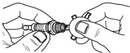
- Inspect electrode gap with wire feeler gauge and reset spark plug gap to 0.028-0.031 in (0.7-0.8 mm). See Figure 4-4.
natural_image
Illustration of hands assembling a mechanical component (no text or symbols visible)000211
Figure 4-4. Spark Plug
NOTE: Replace spark plug if electrodes are pitted, burned or porcelain is cracked. Use ONLY recommended replacement plug. See Specifications.
- Install spark plug finger tight, and tighten an additional 3/8 to 1/2 turn using spark plug wrench.
Battery Replacement (if applicable)
NOTE: The battery shipped with the generator has been fully charged. A battery may lose some charge when not in use for prolonged periods of time.
WARNING
Accidental Start-up. Disconnect the negative battery cable, then the positive battery cable when working on unit. Failure to do so could result in death or serious injury. (000130)

WARNING
Risk of burns. Batteries contain sulfuric acid and can cause severe chemical burns. Wear protective gear when working with batteries. Failure to do so could result in death or serious injury. (000138a)

CAUTION
Do not make battery connections in reverse. Doing so will result in equipment damage.
(000167)
See Figure 4-5.
- Disconnect negative (-) battery terminal FIRST (black wire).
- Disconnect positive (+) battery terminal SECOND (red wire).

001796
Figure 4-5. Battery Connection
- Install new battery. Install hold down bracket and tighten.
- Connect positive (+) battery terminal (red wire) FIRST (red wire). Slide rubber boot over connection hardware.
- Connect negative (-) battery terminal (black wire) SECOND.
- Slide rubber boot over connection hardware.
WARNING
Environmental Hazard. Always recycle batteries at an official recycling center in accordance with all local laws and regulations. Failure to do so could result in environmental damage, death or serious injury. (000228)
Inspect Muffler and Spark Arrester
NOTE: It is a violation of California Public Resource Code, Section 4442, to use or operate the engine on any forest-covered, brush-covered, or grass-covered land unless the exhaust system is equipped with a spark arrester, as defined in Section 4442, maintained in effective working order. Other states or federal jurisdictions may have similar laws.
Contact original equipment manufacturer, retailer, or dealer to obtain a spark arrester designed for exhaust system installed on this engine.
NOTE: Use ONLY original equipment replacement parts.
Inspect muffler for cracks, corrosion, or other damage. Remove spark arrester, if equipped, inspect for damage or carbon blockage. Replace parts as required.
Inspect Spark Arrester Screen (CARB models)

!WARNING
Hot Surfaces. When operating machine, do not touch hot surfaces. Keep machine away from combustibles during use. Hot surfaces could result in severe burns or fire. (000108)
-
See Figure 4-6. Loosen screw and remove retainer clamp (A) and retainer (B).
-
Remove retainer screw (C) from muffler outlet tube.
- Remove screen (D) and replace if torn, perforated or otherwise damaged. If screen is not damaged, clean with commercial solvent.
- Replace screen and retainer, secure with screw.
- Install clamp.
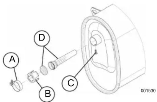
Figure 4-6. Spark Arrestor Screen
Valve Clearance
IMPORTANT NOTE: If uncomfortable about doing this procedure, or the proper tools are not available, take generator to the nearest service center to have valve clearance adjusted.
Check valve clearance after the first fifty-hours of operation. Adjust as necessary.
- Intake — 0.15 ± 0.02mm (cold), (0.006" ± 0.001" inches)
- Exhaust — 0.20 ± 0.02mm (cold) (0.008" ± 0.001" inches)
Storage
General

DANGER
Explosion and Fire. Fuel and vapors are extremely flammable and explosive. Store fuel in a well ventilated area. Keep fire and spark away. Failure to do so will result in death or serious injury. (000143)

WARNING
Risk of Fire. Verify machine has properly cooled before installing cover and storing machine. Hot surfaces could result in fire. (000109)
It is recommended to start and run the generator for 30 minutes, every 30 days. If this is not possible, refer to the following list to prepare unit for storage.
- DO NOT place a storage cover on a hot generator. Allow unit to cool to room temperature before storage.
-
DO NOT store fuel from one season to another unless properly treated.
-
Replace fuel container if rust is present. Rust in fuel will cause fuel system problems.
- Cover unit with a suitable protective, moisture resistant cover.
- Store unit in a clean and dry area.
• Always store generator and fuel away from heat and ignition sources.
Prepare Unit for Storage
Fuel stored over 30 days can go bad and damage fuel system components. Keep fuel fresh, use fuel stabilizer.
If fuel stabilizer is added to fuel system, prepare and run engine for long term storage. Run engine for 10-15 minutes to circulate stabilizer throughout fuel system. Adequately prepared fuel can be stored up to 24 months.
NOTE: If fuel has not been treated with fuel stabilizer, it must be drained into an approved container. Run engine until it stops from lack of fuel. Use of fuel stabilizer in fuel storage container is recommended to keep fuel fresh.
- Change engine oil.
- Remove spark plug.
- Pour tablespoon (5-10cc) of clean engine oil or spray a suitable fogging agent into cylinder.

WARNING
Vision Loss. Eye protection is required to avoid spray from spark plug hole when cranking engine. Failure to do so could result in vision loss. (000181)
- Pull starter recoil several times to distribute oil in cylinder.
- Install spark plug.
- Pull recoil slowly until resistance is felt. This will close valves so moisture cannot enter engine cylinder. Gently release recoil.
- Disconnect negative (-) battery terminal FIRST (black wire).
- Disconnect positive (+) battery terminal SECOND (red wire).
- Remove battery from generator.
- Charge the battery.
- Clean the battery and store in a dry clean environment.
Change Oil
Change engine oil before storage. See Change Engine Oil.
Troubleshooting
| PROBLEM CAUSE | CORRECTION | |
| Engine is running, but AC output is not available. | 1. Circuit breaker OPEN.2. Poor connection or defective cord set.3. Connected device is bad.4. Fault in generator.5. GFCI receptacle is OPEN (if equipped). | 1. Reset circuit breaker.2. Check and repair.3. Connect another device that is in good condition.4. Contact IASD.5. Correct ground fault and press reset button on GFCI receptacle (if equipped). |
| Engine runs well at no-load, but bogs when load is applied. | 1. Short circuit in a connected load.2. Generator is overloaded.3. Engine speed is too slow.4. Shorted generator circuit.5. Dirty fuel filter. | 1. Disconnect shorted electrical load.2. See Know Generator Limits.3. Contact IASD.4. Contact IASD.5. Replace fuel filter. |
| Engine will not crank. 1. 10 | Amp fuse has melted open.2. Battery weak or dead. | 1. Replace fuse.2. Charge or replace battery. |
| Engine will not start; or starts and runs rough. | 1. Off/On/Start Switch is OFF.2. Fuel shut-off is OFF.3. Dirty air filter.4. Out of fuel.5. Stale fuel.6. Dirty fuel filter.7. Spark plug wire not connected to spark plug.8. Bad spark plug.9. Water in fuel.10. Overchoking.11. Low oil level.12. Excessive rich fuel mixture.13. Intake valve stuck open or closed.14. Engine lost compression. | 1. Turn Off/On/Start Switch ON.2. Turn fuel shut-off ON.3. Clean or replace air filter.4. Fill fuel tank.5. Drain fuel tank and fill with fresh fuel.6. Replace fuel filter.7. Connect wire to spark plug.8. Replace spark plug.9. Drain fuel tank; fill with fresh fuel.10. Set choke to no choke position.11. Fill crankcase to correct level.12. Contact IASD.13. Contact IASD.14. Contact IASD. |
| Engine shuts down during operation. | 1. Out of fuel.2. Dirty fuel filter.3. Low oil level.4. Fault in engine. | 1. Fill fuel tank.2. Replace fuel filter.3. Fill crankcase to correct level.4. Contact IASD. |
| Engine lacks power. 1. Load is too high.2. Dirty air filter.3. Dirty fuel filter.4. Engine needs to be serviced. | 1. Reduce load (see Know Generator Limits).2. Clean or replace air filter.3. Dirty fuel filter.4. Contact IASD. | |
| Engine surges or stumbles. | 1. Choke is opened too soon.2. Carburetor is running too rich or too lean.3. Dirty fuel filter. | 1. Set choke to halfway position until engine runs smoothly.2. Contact IASD.3. Dirty fuel filter. |
| No battery charge DC output. | 1. Battery posts corroded.2. Bad battery cable.3. Defective battery.4. Bad receptacle. | 1. Clean battery posts.2. Replace cable.3. Check battery condition.Replace if defective.4. Contact IASD. |
Notes
Powermate®
Part No. 10000001769 Rev. B 05/17/16
©2016 Powermate All rights reserved.
Specifications are subject to change without notice.
No reproduction allowed in any form without prior
written consent from Powermate.
Powermate, LLC
S45 W29290 Hwy. 59
Waukesha, WI 53189
1-800-445-1805
www.powermate.com
Generadores portátiles CX6500E y CX8000E
natural_image
Technical line drawing of a portable gas generator with wheels and control panel (no text or symbols)MODELO:
SERIE:
FECHA DE COMPRA:

ADVERTENCIA
Hearing protection recommended.
PRECAUCIÓN
natural_image
Pure electrical circuit lines without any symbols000203
natural_image
Circular diagram with concentric rings and four black curved segments arranged in a cross pattern (no text or symbols)000204
Figura 2-5. Tomacorriente de 120/240 VCA, 30 A NEMA L14-30R
Tomacorriente de 120 VCA, 30 A
natural_image
Circular diagram with three curved arrows forming a loop (no text or symbols)000844
Figura 2-6. Tomacorriente de 120 VCA, 30 A NEMA L5-30
natural_image
Illustration of a hand turning a valve with a curved arrow indicating rotation (no text or symbols)natural_image
Technical line drawing of a mechanical component with threaded end and textured base (no text or symbols)natural_image
Illustration of a mechanical device with a rotating arrow and a boat (no text or symbols)natural_image
Technical line drawing of a mechanical connector or connector assembly (no text or symbols)natural_image
Technical line drawing of a mechanical component with labeled section A (no text or symbols beyond label)000379
natural_image
Illustration of hands assembling a mechanical component (no text or symbols visible)000211
Figura 4-4. Bujía
natural_image
Technical line drawing of a portable gas generator with wheels and control panel (no text or symbols)MODÈLE :
NO DE SÉRIE : ____
DATE D'ACHAT : ____

AVERTISSEMENT
natural_image
Pure electrical circuit lines without any symbolsnatural_image
Circular diagram with four black curved segments arranged in a cross pattern (no text or symbols)000204
Figure 2-5. Prise de courant NEMA L14-30R, de 120/240 V c.a., 30 A
natural_image
Circular diagram with three curved black segments and a central arrow, no text or symbols present.000844
Figure 2-6. Prise de courant NEMA L5-30 de 120 V c.a., 30 A
natural_image
Illustration of a mechanical device with a rotating arrow and component, no text or symbols presentnatural_image
Technical line drawing of a mechanical component with threaded end and threaded shaft (no text or symbols)natural_image
Illustration of a hand holding a tool with a circular arrow indicating rotation (no text or symbols)natural_image
Technical line drawing of a mechanical component with threaded end and textured base (no text or symbols)natural_image
Technical line drawing of a mechanical device with pipes and housing (no text or symbols)000379
natural_image
Illustration of hands assembling a mechanical component (no text or symbols visible)000211
- WARNING
- Section 1 Introduction and Safety 1
- Section 2 General Information and
- Setup 4
- Section 3 Operation .... 10
- Section 4 Maintenance and
- Troubleshooting ....13
- Section 1 Introduction and Safety
- Introduction
- Safety Rules
- DANGER
- CAUTION
- Safety Symbols and Meanings
- !WARNING
- Exhaust and Location Hazards
- Electrical Hazards
- Fire Hazards
- ADANGER
- Standards Index
- Know Your Generator
- Emissions
- Connection Plugs
- VAC, 20 Amp, GFCI Duplex Receptacle
- 120/240 VAC, 30 Amp Receptacle
- VAC, 30 Amp Receptacle
- Remove Contents from Carton
- Assembly
- Battery Cable Connection (electric start only)
- Add Engine Oil
- Fuel
- Section 3 Operation
- Operation and Use Questions
- Before Starting Engine
- Prepare Generator for Use
- Grounding the Generator When In Use
- Special Requirements
- Connecting the Generator to a Building Electrical System
- Know Generator Limits
- Transporting/Tipping of the Unit
- Starting Pull Start Engines
- Starting Electric Start Engines
- Generator Shut Down
- Low Oil Level Shutdown System
- Section 4 Maintenance and Troubleshooting
- Maintenance
- Maintenance Schedule
- Preventive Maintenance
- Engine Maintenance
- Engine Oil Recommendations
- Inspect Engine Oil Level
- Change Engine Oil
- Air Filter
- Service Spark Plug
- Battery Replacement (if applicable)
- See Figure 4-5.
- Inspect Muffler and Spark Arrester
- Inspect Spark Arrester Screen (CARB models)
- Valve Clearance
- Storage
- General
- Prepare Unit for Storage
- Change Oil
- Notes
- Powermate®
- Generadores portátiles CX6500E y CX8000E
- ADVERTENCIA
- PRECAUCIÓN
- Tomacorriente de 120 VCA, 30 A
- AVERTISSEMENT
Brand : Powermate
Model : CX6500E
Category : Generator