N8000MI - Intercom TOA - Free user manual and instructions
Find the device manual for free N8000MI TOA in PDF.

User questions about N8000MI TOA
0 question about this device. Answer the ones you know or ask your own.
Ask a new question about this device
Download the instructions for your Intercom in PDF format for free! Find your manual N8000MI - TOA and take your electronic device back in hand. On this page are published all the documents necessary for the use of your device. N8000MI by TOA.
USER MANUAL N8000MI TOA
MULTI INTERFACE UNIT N-8000MI
natural_image
Line drawing of a rectangular electronic device with ports and ventilation slots (no text or symbols)TABLE OF CONTENTS
- SAFETY PRECAUTIONS ...... 2
- GENERAL DESCRIPTION .... 5
- FEATURES 5
- SPECIFICATIONS 6
- SYSTEM CONFIGURATION EXAMPLE ..... 7
- NOMENCLATURE AND FUNCTIONS ..... 8
Front 8
Rear 8 - INSTALLATION 9
7.1. Equipment Rack Mounting 9
7.2. Desk-Top Installation 11
7.3. Wall Mounting 11
- WIRING 12
8.1. Connection Diagram 12
8.2. Type of Cable 15
8.3. Connector Connection 15
- ACCESSORIES 16
1. SAFETY PRECAUTIONS
- Before installation or use, be sure to carefully read all the instructions in this section for correct and safe operation.
- Be sure to follow all the precautionary instructions in this section, which contain important warnings and/or cautions regarding safety.
• After reading, keep this manual handy for future reference.
Safety Symbol and Message Conventions
Safety symbols and messages described below are used in this manual to prevent bodily injury and property damage which could result from mishandling. Before operating your product, read this manual first and understand the safety symbols and messages so you are thoroughly aware of the potential safety hazards.

WARNING
Indicates a potentially hazardous situation which, if mishandled, could result in death or serious personal injury.
When Installing the Unit
- Do not expose the unit to rain or an environment where it may be splashed by water or other liquids, as doing so may result in fire or electric shock.
- Use the unit only with the voltage specified on the unit. Using a voltage higher than that which is specified may result in fire or electric shock.
- Do not cut, kink, otherwise damage nor modify the power supply cord. In addition, avoid using the power cord in close proximity to heaters, and never place heavy objects -- including the unit itself -- on the power cord, as doing so may result in fire or electric shock.
- Avoid installing or mounting the unit in unstable locations, such as on a rickety table or a slanted surface. Doing so may result in the unit falling down and causing personal injury and/or property damage.
- Install the unit only in a location that can structurally support the weight of the unit and the mounting bracket. Doing otherwise may result in the unit falling down and causing personal injury and/or property damage.
When the Unit is in Use
- Should the following irregularity be found during use, immediately switch off the power, disconnect the power supply plug from the AC outlet and contact your nearest TOA dealer. Make no further attempt to operate the unit in this condition as this may cause fire or electric shock.
- If you detect smoke or a strange smell coming from the unit.
- If water or any metallic object gets into the unit
- If the power supply cord is damaged (exposure of the core, disconnection, etc.)
-
If it is malfunctioning (no tone sounds.)
-
To prevent a fire or electric shock, never open nor remove the unit case as there are high voltage components inside the unit. Refer all servicing to your nearest TOA dealer.
- Do not touch a plug during thunder and lightning, as this may result in electric shock.

CAUTION
Indicates a potentially hazardous situation which, if mishandled, could result in moderate or minor personal injury, and/or property damage.
When Installing the Unit
- Never plug in nor remove the power supply plug with wet hands, as doing so may cause electric shock.
- When unplugging the power supply cord, be sure to grasp the power supply plug; never pull on the cord itself. Operating the unit with a damaged power supply cord may cause a fire or electric shock.
- Do not block the ventilation slots in the unit's cover. Doing so may cause heat to build up inside the unit and result in fire.
-
Be sure to follow the instructions below when rack-mounting the unit. Failure to do so may cause a fire or personal injury.
-
Install the equipment rack on a stable, hard floor. Fix it with anchor bolts or take other arrangements to prevent it from falling down.
- To rack-mount the unit, use the supplied rack mounting hardware.
- When connecting the unit's power cord to an AC outlet, use the AC outlet with current capacity allowable to the unit.
When the Unit is in Use
- Do not place heavy objects on the unit as this may cause it to fall or break which may result in personal injury and/or property damage. In addition, the object itself may fall off and cause injury and/or damage.
- Do not stand or sit on, nor hang down from the unit as this may cause it to fall down or drop, resulting in personal injury and/or property damage.
This device is a Class I product.
Connect the supplied power cord only to the AC outlet with a ground terminal. Doing otherwise may result in electric shock.
CONSEILS DE SÉCURITÉ
The N-8000MI is a multi interface unit designed for use with TOA's packet intercom system (IP network-compatible intercom system) that employs the packet audio technology*. Connecting the multi interface to a local area network permits the ideal system for in-house or wide-area information transmission applications, such as paging, periodical broadcasts, and background music broadcasts, to be built between the multi interface and IP intercom exchange or other multi interface unit. The contact bridge function can be realized through contact input and output control.
* Technology related to audio transmission over a network.
Warning
This is a class A product. In a domestic environment this product may cause radio interference in which case the user may be required to take adequate measures.
DESCRIPTION GÉNÉRALE
- N-8000MI units can be distributed over a data communications network.
- Can be connected to an existing local area network (LAN) or wide-area network (WAN). The unit can also be easily connected to fiber-optic networks without restrictions on operating distance.
- The dedicated software program enables centralized control with a personal computer.
- System maintenance (verifying operation log and Line supervision) can also be performed with a personal computer and Internet browser.
- Can be connected to the Exchange of the EXES-2000 or EXES-6000 Intercom System by a tie-line, or the PBX exchange via the OD (out-band-dialing) trunk.
- The unit can interlock with an electronic lock system or CCTV surveillance system by way of contact input/output control function.
CARACTÉRISTIQUES
Connectable to LAN: Maximum 192 (a total of Exchanges and Multi Interface Units)
Speech Link Capacity 2 links
Speech (through the PBX or tie-line): Maximum 2 links
Audio input: Maximum 2 links
Audio output: Maximum 2 links
Note
The above links can be simultaneously used.
(Refer to the table in the next page.)
Simultaneous access capacity for paging links
Multicast paging: Maximum 2 links
Unicast paging: 1 link
Paging Zones: Maximum 384 (With 192 Multi Interface Units)
Paging Zone Via Network: Maximum 191 (Multicast paging), Maximum 16 (Unicast paging)
BGM Input: Maximum 8 channels (Number of inputs per exchange)
PBX Interface: Maximum 384 (When 192 Multi Interface Units are connected)
Tie-line Interface: Maximum 384 (When 192 Multi Interface Units are connected)
External Contact Output: Maximum 384 (When 192 Multi Interface Units are connected)
External Contact Input: Maximum 384 (When 192 Multi Interface Units are connected)
System Settings: Personal computer setting using a dedicated software program (over LAN)
(Network Related)
Voice Delay Time: 80 or 320 ms, selectable
Connection Delay Time: Maximum 1 second (When multicast paging is made to 191 zones)
Usage Bandwidth: Maximum 2.08 Mbps (one way)/When 16 Unicast paging are made
Maximum 130 kbps (two-way)/one call
5. SYSTEM CONFIGURATION EXAMPLE
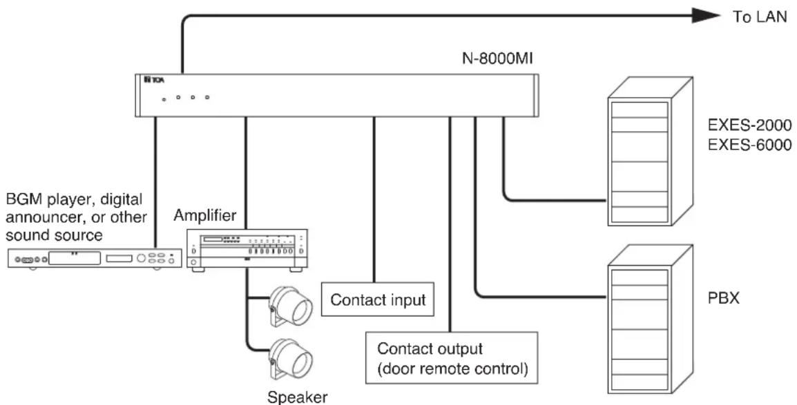
flowchart
graph TD
    A["BGM player, digital announcer, or other sound source"] --> B["Amplifier"]
    B --> C["N-8000MI"]
    C --> D["To LAN"]
    C --> E["EXES-2000 EXES-6000"]
    C --> F["PBX"]
    C --> G["Contact input"]
    G --> H["Speaker"]
    G --> I["Contact output (door remote control)"]
Having 2 channels each for audio input and output, and 16 contacts each for control input and output, the N-8000MI performs the following interface functions*.
- Tie-line interface for connection with the EXES-2000 and EXES-6000 systems.
- PBX interface for connection with the PBX via the OD trunk.
- PA paging interface for connection with PA equipment
- External input broadcast interface for connection with a music player (chime unit) or paging microphone irrespective of with or without remote control function.
- Interface to control an indicator or external equipment such as a CCTV's switcher using relay contacts.
The N-8000MI also features Network interface for connection with an IP intercom exchange or other multi interface unit.
* The interface functions can be combined in the following 9 patterns.
6. NOMENCLATURE AND FUNCTIONS
[Front]
![TOA N8000MI - [Front] - 1](/content/2026/03/525192/images/cc6902ba5dd77e5c45533a9baeb18587cf19da98e711d374ac067fefb53d60ce.jpg)
text_image
①②③④⑤ TOA RESET LNK/ACT STATUS POWER 00-05-F9-FF-00-00 MULTI INTERFACE UNIT N=8000M1. Reset key [RESET]
Pressing this key reactivates the exchange.
2. LNK/ACT indicator [LNK/ACT] (Green)
Lights when connected to a network, and flashes while transmitting or receiving data.
3. Status indicator [STATUS] (Red)
Continuously lights while data is written to an internal storage medium (FlashMemory). Flashes if there is a failure.
4. Power indicator [POWER] (Green)
Lights when power is supplied to the unit.
5. MAC address
This is the address ^*1 used by the unit. Since the relationship of each exchange location to its MAC address is established when setting the network attributes, keep track of this relationship for later use.
*1 The inherent address assigned to each network component, expressed in 12-digit hexadecimal notation.
[Rear]
![TOA N8000MI - [Rear] - 1](/content/2026/03/525192/images/408fff5ab822ee21b1d2ffab698e6b65c950b253c7d2ee2a6d0c9cbdf0fdb7f3.jpg)
text_image
SIGNAL GND 1-8 C 9-16 C CONTACT IN CONTACT OUT EXTERNAL SIGNAL CH1 CH2 AUDIO CTRL AUDIO CTRL CH1 CH2 AUDIO CTRL AUDIO CTRL CH1 CH2 V F TX RX TX RX PBX F MULTI INTERFACE UNIT model N=8000MI TOA Corporation MADE IN JAPAN ⑥ ⑦ ⑧ ⑨ ⑩ ⑪ ⑫ ⑬ ⑭ ⑬ ⑭ ⑮ ⑯ ⑰ ⑱ ⑲6. Functional earth terminal [SIGNAL GND]
Be sure to ground this terminal unless the unit connects to a PBX.
Note: This terminal is not for protective earth.
7. AC inlet
Connects the supplied power cord.
8. Cord clamp
Pass the power cord through this clamp to ensure that the plug does not pull out when the unit is mounted to a wall. (Refer to p. 11)
9. Contact input terminals [CONTACT IN]
No-voltage make contact inputs.
Short-circuit current: 10 mA, Open-circuit voltage: 12 V
10. Contact output terminals [CONTACT OUT]
Relay contact outputs.
Withstand voltage: 24 V DC, Control current: Maximum 0.5 A
11. Audio input level controls [EXTERNAL SIGNAL 1, 2]
Use these controls to adjust the audio input
levels for channels 1 and 2 according to the input sources.
12. Audio input terminal [AUDIO IN]
Includes audio inputs (maximum 0 dB ^*2 , over 10 kΩ, balanced) and contact inputs (no-voltage make contact, short-circuit current: 10 mA, open-circuit voltage: 12 V).
13. Audio output terminal [AUDIO OUT]
Includes audio outputs (maximum 0 dB ^*2 , under 600 , balanced) and control outputs (relay contact withstand voltage: 24 V DC, control current: maximum 0.5 A).
14. PBX interface terminal [PBX IF]
Connects to the Exchange of the EXES-2000 or EXES-6000 system by a tie-line, or the PBX exchange via the OD (out-band-dialing) trunk.
15. Network connection terminal [10/100M]
Connects to a 10BASE-T- or 100BASE-TX-compatible network. (Ethernet RJ45 jack)
$$ ^ {* 2} 0 \mathrm{dB} = 1 \mathrm{V} $$
7. INSTALLATION
The N-8000MI can be installed in any of three ways: Equipment rack mounting, Desk-top installation, and Wall mounting.
7.1. Equipment Rack Mounting
The N-8000MI can be mounted on the CR-273 or CR-413 or standard EIA 19" Equipment rack.
For the CR-273 and CR-413 Equipment rack assembly, read the installation manual supplied with the rack.
Note
When installing the N-8000MI, lay the equipment rack down face-up to do installation work safely.
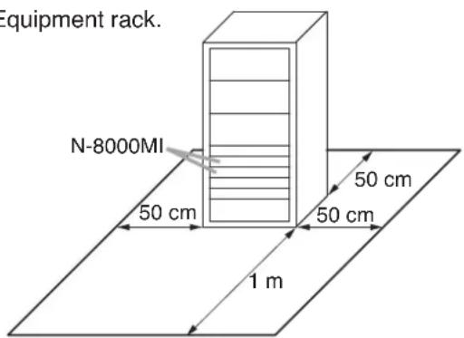
7.1.1. Setting space
For maintenance works, allow much space between the wall and Equipment rack.
text_image
Equipment rack. N-8000MI 50 cm 50 cm 50 cm 1 m7.1.2. Caution when installing the unit

CAUTION
Do not block the ventilation slots in the unit's cover. Doing so may cause heat to build up inside the unit and result in fire.
Do not stack up 3 units or more. If 2 or more units are mounted in the Equipment rack, be sure to mount the perforated panel of 1 U size (PF-013B) or more above and below every 2 units.
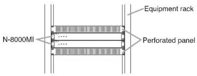
text_image
N-8000MI Equipment rack Perforated paneltext_image
N-8000MI Rack mounting bracket (accessory) Patte de montage (accessoire) Tapping screw 3 x 8 (accessory) Vis-taraud 3 x 8 (accessoire) 2 1Step 1. Install the rack-mounting bracket to the N-8000MI.
Step 2. Mount the N-8000MI on the Equipment rack.
Rack mounting screw 5 x 12 with plain washer (accessory)
When installing the N-8000MI on a desk, secure the supplied plastic feet to the unit's Machine screw M4 x 20 bottom using the supplied tapping screws. (accessory) Vis de mécanique M4 x 20
Step 1. Install the supplied wall-mounting bracket to the N-8000MI using 4 removed screws from the case.
Step 2. Mount the N-8000MI on the wall. Notes
- Use appropriate screws for the construction of wall.
- Wood screws 3.5 x 20 are supplied with the N-8000MI.
- The socket-outlet shall be installed near the equipment and shall be easily accessible.
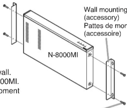
text_image
Wall mounting (accessory) Pattes de mon (accessoire) N-8000MI wall. 00MI. pementWall mounting bracket (accessory) Pattes de montage mural (accessoire)
Protect against disconnection (Power supply plug)
Unlock cord clamp and run the power supply cord through it.
Note
Keep the cable length between a power supply plug and cord clamp as short as possible.
Wood screw 3.5 x 20 (accessory)
8.1. Connection Diagram
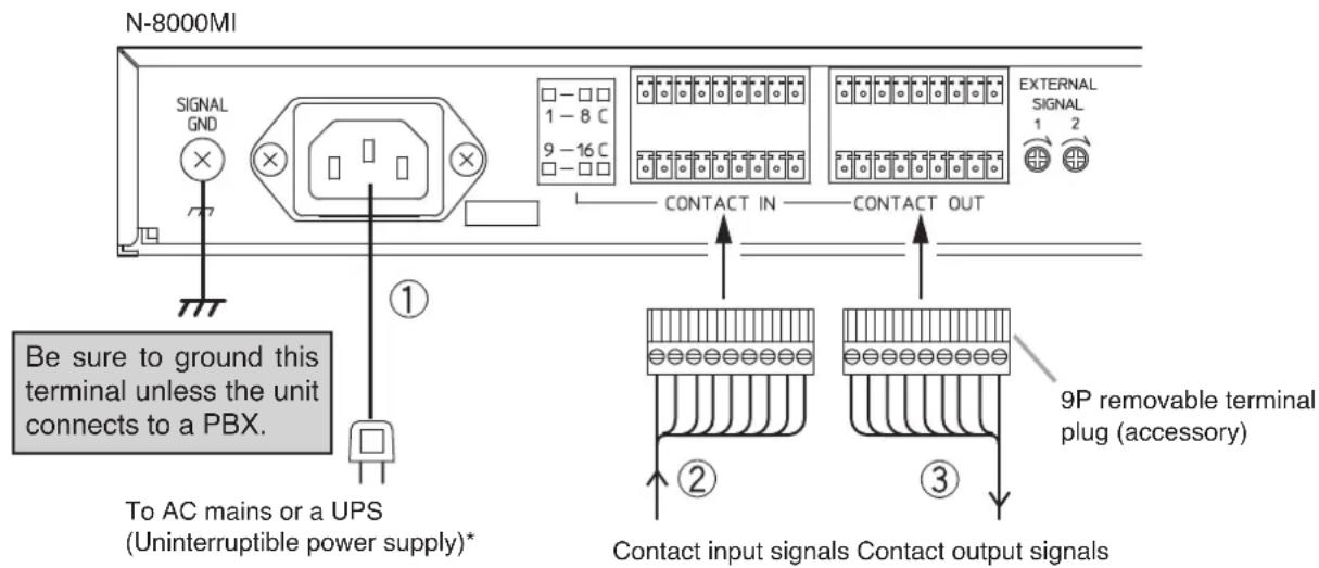
text_image
N-8000MI SIGNAL GND 1 - 8 C 9 - 16 C □ - □ □ □ - □ □ □ - □ □ CONTACT IN CONTACT OUT Be sure to ground this terminal unless the unit connects to a PBX. To AC mains or a UPS (Uninterruptible power supply)* ① ② ③ 9P removable terminal plug (accessory) Contact input signals Contact output signalsNote
If there is a danger of lightning strikes, insert an appropriate surge arrester into the power line.
[General description of connection]
For cables, refer to p. 15.
1. Power supply connection
Connect the supplied power supply cord to AC Mains or a UPS (Uninterruptible power supply).
About power supply cord handling
The supplied power supply cord is designed for exclusive use with the N-8000MI. Use the supplied power supply cord only with the N-8000MI.
2. Contact input terminal connection
(Refer to p. 15, "Connector Connection.")
[Specification of no-voltage make contact input]
Short-circuit current: 10 mA
Open-circuit voltage: 12 V
3. Contact output terminal connection
Contact output terminals have no polarity. (Refer to p. 15, "Connector Connection.")
[Specification of relay contact output]
Withstand voltage: 24 V DC
Control current: Max. 0.5 A
* Select an appropriate UPS taking into consideration the total power consumption of all system components and the required backup time, and also the requirement that the UPS should employ the on-line power system.
Reference
Multi Inertface Unit: Maximum 19 W.
8-Port 10M/100M Switching Hub: 10 W (Differs depending on products.)
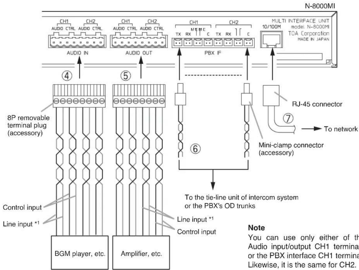
text_image
N-8000MI CH1 CH2 CH1 CH2 CH1 CH2 AUDIO CTRL AUDIO CTRL AUDIO IN AUDIO OUT PBX IF MULTI INTERFACE UNIT model N-8000MI TOA Corporation MADE IN JAPAN ④ ⑤ 8P removable terminal plug (accessory) Control input Line input *1 BGM player, etc. Amplifier, etc. Line input *1 Control input To network RJ-45 connector Mini-clamp connector (accessory) To the tie-line unit of intercom system or the PBX's OD trunks Note You can use only either of the Audio input/output CH1 termina or the PBX interface CH1 termina Likewise, it is the same for CH2.Note
You can use only either of the Audio input/output CH1 terminals or the PBX interface CH1 terminal. Likewise, it is the same for CH2.
*1 Connect the Line input cables in a way as shown below according to the type of connected unit's input or output.
- Connecting to a balanced input or output

text_image
N-8000MI { Hot (H) } Connected Unit Cold (C) Earth (E)- Connecting to an unbalanced input or output

text_image
N-8000MI { Hot (H) } Connected Unit Earth (E)4. Audio input terminal connection
Audio input terminals have no polarity.
(Refer to p. 16, "Terminal plug connection.")
[Specification of auidio input]
Max. 0 dB ^2 , over 10 kΩ, balanced
[Specification of control input]
No-voltage make contact
Short-circuit current: 10 mA
Open-circuit voltage: 12 V
5. Audio output terminal connection
Audio output terminals have no polarity.
(Refer to p. 16, "Terminal plug connection.")
[Specification of audio output]
Max. 0 dB ^*2 , under 600 Ω, balanced
[Specification of control output]
Relay contact
Withstand voltage: 24 V DC
Control current: Max. 0.5 A
6. PBX interface terminal connection
Differs depending on the connections to the Exchange of the EXES-2000 or EXES-6000 by a tie-line, or to the PBX exchange via the OD (out-band-dialing) trunk.
(Refer to p. 15, "Connector Connection.")
7. Network connection
Can be connected to a network of 10BASE-T/100BASE-TX in auto-sensing.
Use a UTP category 5 straight-through cable for this connection.
*2 0 dB = 1 V
[Connecting to the PBX's OD trunk]
Connect the PBX's transmitting line to the unit's RX terminal, and the PBX's receiving line to the TX terminal. Also connect the PBX's M (Mouth) line to the unit's E (Ear) terminal, and the PBX's E line to the M terminal.
![TOA N8000MI - [Connecting to the PBX's OD trunk] - 1](/content/2026/03/525192/images/05147c5b4cec5b7945c1e43b17e6d8217769617c58df1fdb6baac2e8bd298457.jpg)
text_image
CH1 TX RX C M E CH2 N-8000MI's PBX interface terminal To PBX's ground point To PBX OD trunk's M and E lines To PBX OD trunk's transmitting line (T2) To PBX OD trunk's receiving line (R2) To PBX's ground point To PBX OD trunk's M and E lines To PBX OD trunk's transmitting line (T1) To PBX OD trunk's receiving line (R1) 2 channelsNote
Do not ground the Functional earth terminal (No. 6 on p. 8) in this PBX connection.
[Connecting to the Intercom's Tie-Line Unit]
Connect the intercom's transmitting line to the unit's RX terminal, and the receiving line to the TX terminal.
![TOA N8000MI - [Connecting to the Intercom's Tie-Line Unit] - 1](/content/2026/03/525192/images/e30b3ce974d7e4e078957f37d22d99cca39cbe80a74ce90f87b0f928bb1ee05c.jpg)
text_image
CH1 CH2 TX RX C M E TX RX C M E N-8000MI's PBX interface terminal To Intercom's transmitting line (T1) To Intercom's transmitting line (T2) To Intercom's receiving line (R1) To Intercom's receiving line (R2) 2 channels8.2. Type of Cable
The types of cables are to be determined according to the following conditions.
- Twisted pair wires (such as those used for electronic push-button telephone) are to be used for wiring to the audio input/output terminals and PBX interface terminal.
- UTP category 5 Straight through cables with RJ45 connector are to be used for wiring the equipments connected to IP network.
- The number of cables pairs laid should be determined considering the possibility of future expansion of the system.
- Outdoor wires should be used where wiring passes through inaccessible areas such as ceilings or under floors where the maintenance is not performed. Indoor wires may also be used, however, in case where there is no risk of deterioration due to exposure to heat, etc.
Note
Specifications related to each junction are as follows.
Mini-clamp connector (PBX interface terminal)
Conductor diameter: 0.4 – 0.65 mm (AWG22 – 26), Solid wire
Outside diameter: 1.05 mm or below
Removable terminal plug (Control input/output terminals and audio input/output terminals)
Conductor diameter: 0.5 – 2 mm (AWG12 – 24), Solid wire/Stranded wire
8.3. Connector Connection
Mini-clamp connectors for PBX interface terminals and removable terminal plugs for line input and output terminals are supplied with the N-8000MI.
Perform each connector connection as follows.
8.3.1. Mini-clamp connector connection
Step 1. Cut off two-cable ends in equal length, and insert them securely to a cover section (transparent side) of the mini-clamp connector.
Note
Insert the cable without stripping the cable jacket. For cables, refer to the above section, Type of Cable.
Cover (transparent side)
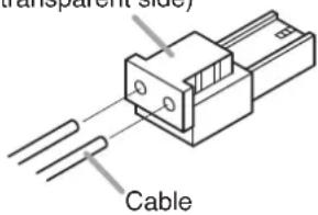
text_image
Transparent Side CableStep 2. With a pair of pliers, lightly pinch the mini-clamp cover and, after ensuring that the cable is securely inserted, firmly squeeze on the cover.
Note
Squeeze on the mini-clamp cover until it is correctly locked.
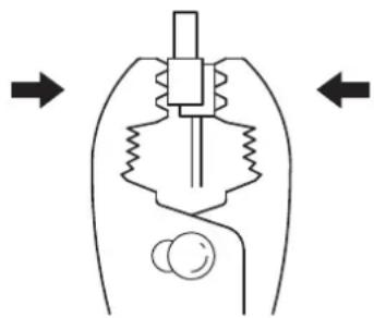
natural_image
Diagram of a mechanical device with internal components and directional arrows (no text or labels)Step 3. Insert the wired plug into the N-8000MI's socket until it locks into place.
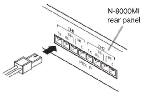
text_image
N-8000MI rear panel CH1 TX RX SR C TX RX SR I CH2 PBX F8.3.2. Terminal plug connection
Step 1. Strip a cable jacket of approx. 7 mm from the cable end.
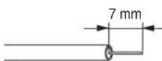
For cables, refer to p. 15, "Type of Cable."
Note
Do not solder plate on exposed inner cables when using a stranded wire.
Step 2. Loosen the terminal screws and insert the cables.
Step 3. Tighten the terminal screws securely. Notes
- Tug lightly on the cable to be sure that it does not pull free. If the cable pulls free, loosen the terminal screw again and reconnect from Step 2.
- Use the screwdriver appropriate to the screws tightened into the terminal plug.
Step 4. Insert the wired terminal plug into the terminal block.
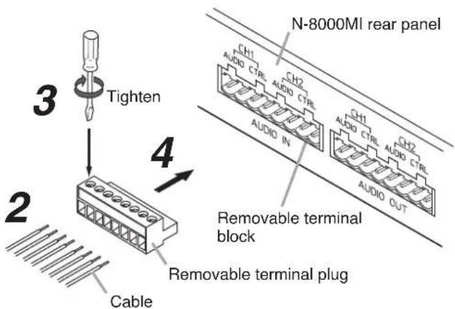
text_image
3 Tighten N-8000MI rear panel 4 2 Cable Removable terminal block Removable terminal plug9. ACCESSORIES
AC power cord (2 m) 1
CD ^* 1
Removable terminal plug (9 pins) 4
Removable terminal plug (8 pins) 2
Mini-clamp connector (2 pins) 10
Plastic foot 4
Machine screw M4 x 20 4
Rack mounting bracket 2
Tapping screw 3 x 8 8
Rack mounting screw 5 x 12 with plain washer ..... 4
Wall mounting bracket 2
Wood screw 3.5 x 20 4
* Contains the N-8000 setting software program and the N-8000 series instruction manual. The Setup Launcher is automatically started when the supplied CD-ROM is inserted into the PC's drive.
Note
If your PC's CD drive is not compatible with the AutoRun function, the setup guide is not automatically started even when the CD is inserted. Use either "Explorer" or "My Computer" to execute the following files, or use [Start -Run] in the Task Bar and enter the following command.
For example, when placing the CD in the "d" drive, -d:\index.html
Version update information
- Download our TOA Products Data, web site (https://www.toa-products.com/international/) to get the up-to-date version for N-8000 software, firmware, and Instruction manuals.
- The software version number can be confirmed using the Help menu.
- The current firmware version can be confirmed on the system management screen displayed when the browser establishes the connection to the Multi Interface Unit.
- The instruction manual version number can be confirmed by checking the preparation date (month and year) shown at the lower right corner of the last page.
Example: Prepared in November 2004: 200411