
DA-250FH CU - Microphone TOA - Free user manual and instructions
Find the device manual for free DA-250FH CU TOA in PDF.


| Product Type | Dynamic Microphone |
| Polar Pattern | Cardioid |
| Frequency Response | 50 Hz – 15 kHz |
| Impedance | 600 ohms |
| Sensitivity | -56 dB (1V/Pa at 1 kHz) |
| Connector | 3-pin XLR |
| Dimensions | 50 mm diameter, 180 mm length |
| Weight | 300 g |
| Material | Die-cast metal body |
| On/Off Switch | Yes, with locking function |
| Cable | Not included (XLR cable required) |
| Application | Public address, speech, live performance |
| Accessories Included | Microphone clip, carrying case |
| Cleaning | Wipe with dry cloth; avoid moisture |
| Safety | Do not drop or expose to extreme temperatures |
| Repairability | Replacement capsule available; contact TOA service |
Frequently Asked Questions - DA-250FH CU TOA
User questions about DA-250FH CU TOA
0 question about this device. Answer the ones you know or ask your own.
Ask a new question about this device
Download the instructions for your Microphone in PDF format for free! Find your manual DA-250FH CU - TOA and take your electronic device back in hand. On this page are published all the documents necessary for the use of your device. DA-250FH CU by TOA.
USER MANUAL DA-250FH CU TOA
Note: The figure shows the DA-250F.
An all-pole mains switch with a contact separation of at least 3 mm (0.12") in each pole shall be incorporated in the electrical installation of the building.
Thank you for purchasing TOA's Multichannel Power Amplifier.
Please carefully follow the instructions in this manual to ensure long, trouble-free use of your equipment.
TABLE OF CONTENTS
- IMPORTANT SAFETY INSTRUCTIONS ...... 3
- SAFETY PRECAUTIONS 4
- GENERAL DESCRIPTION ...... 6
- FEATURES 6
- HANDLING PRECAUTIONS ...... 6
-
INSTALLATION PRECAUTIONS ...... 7
-
NOMENCLATURE AND FUNCTIONS
Front 8
Rear 9
- SETTINGS AND CONNECTIONS
8.1. Switch Settings and Speaker Connections ...... 10
-
REMOVABLE TERMINAL PLUG CONNECTION 12
-
INPUT SENSITIVITY AND HIGH-PASS FILTER ON/OFF SETTINGS .... 13
-
PROTECTION OPERATION LIST 14
-
TAMPER-PROOF CAP ATTACHMENT 14
-
CLEANING THE FILTER 15
-
BLOCK DIAGRAMS
14.1. DA-250F 16
14.2. DA-250FH 17
-
DIMENSIONAL DIAGRAM 18
-
SPECIFICATIONS
16.1. DA-250F CU 19
16.2. DA-250FH CU 20
1. IMPORTANT SAFETY INSTRUCTIONS
- Read these instructions.
- Keep these instructions.
- Heed all warnings.
- Follow all instructions.
- Do not use this apparatus near water.
- Clean only with dry cloth.
- Do not block any ventilation openings. Install in accordance with the manufacturer's instructions.
- Do not install near any heat sources such as radiators, heat registers, stoves, or other apparatus (including amplifiers) that produce heat.
- Do not defeat the safety purpose of the polarized or grounding-type plug. A polarized plug has two blades with one wider than the other. A grounding type plug has two blades and a third grounding prong. The wide blade or the third prong are provided for your safety. If the provided plug does not fit into your outlet, consult an electrician for replacement of the obsolete outlet.
- Protect the power cord from being walked on or pinched particularly at plugs, convenience receptacles, and the point where they exit from the apparatus.
- Only use attachments/accessories specified by the manufacturer.
- Use only with the cart, stand, tripod, bracket, or table specified by the manufacturer, or sold with the apparatus. When a cart is used, use caution when moving the cart/apparatus combination to avoid injury from tip-over.

- Unplug this apparatus during lightning storms or when unused for long periods of time.
- Refer all servicing to qualified service personnel. Servicing is required when the apparatus has been damaged in any way, such as power-supply cord or plug is damaged, liquid has been spilled or objects have fallen into the apparatus, the apparatus has been exposed to rain or moisture, does not operate normally, or has been dropped.
FCC REQUIREMENTS
Note: This equipment has been tested and found to comply with the limits for a Class A digital device, pursuant to part 15 of the FCC Rules. These limits are designed to provide reasonable protection against harmful interference when the equipment is operated in a commercial environment. This equipment generates, uses, and can radiate radio frequency energy and, if not installed and used in accordance with the instruction manual, may cause harmful interference to radio communications. Operation of this equipment in a residential area is likely to cause harmful interference in which case the user will be required to correct the interference at his own expense.
- Reorient or relocate the receiving antenna.
- Increase the separation between the equipment and receiver.
- Connect the equipment into an outlet on a circuit different from that to which the receiver is connected.
-
Consult the dealer or an experienced radio/TV technician for help.
-
This Class A digital apparatus complies with Canadian ICES-003.
- Cet appareil numérique de la classe A est conforme à la norme NMB-003 du Canada.
2. SAFETY PRECAUTIONS
- Before installation or use, be sure to carefully read all the instructions in this section for correct and safe operation.
- Be sure to follow all the precautionary instructions in this section, which contain important warnings and/or cautions regarding safety.
• After reading, keep this manual handy for future reference.
Safety Symbol and Message Conventions
Safety symbols and messages described below are used in this manual to prevent bodily injury and property damage which could result from mishandling. Before operating your product, read this manual first and understand the safety symbols and messages so you are thoroughly aware of the potential safety hazards.

WARNING
Indicates a potentially hazardous situation which, if mishandled, could result in death or serious personal injury.

CAUTION
Indicates a potentially hazardous situation which, if mishandled, could result in moderate or minor personal injury, and/or property damage.

WARNING
When Installing the Unit
- Do not expose the unit to rain or an environment where it may be splashed by water or other liquids, as doing so may result in fire or electric shock.
- Use the unit only with the voltage specified on the unit. Using a voltage higher than that which is specified may result in fire or electric shock.
- Do not cut, kink, otherwise damage nor modify the power supply cord. In addition, avoid using the power cord in close proximity to heaters, and never place heavy objects -- including the unit itself -- on the power cord, as doing so may result in fire or electric shock.
- Be sure to replace the unit's terminal cover after connection completion. Because the voltage of up to 140 V is applied to the high impedance speaker terminals, never touch these terminals to avoid electric shock. (DA-250FH only)
- External wiring connected to the terminals marked with requires installation by an instructed person. (DA-250FH only)
- The apparatus shall be connected to a mains socket outlet with a protective earthing connection.
When the Unit is in Use
- Should the following irregularity be found during use, immediately turn off this unit's power switch, disconnect the power supply plug from the AC outlet and contact your nearest TOA dealer. Make no further attempt to operate the unit in this condition as this may cause fire or electric shock.
- If you detect smoke or a strange smell coming from the unit.
- If water or any metallic object gets into the unit
· If the unit falls, or the unit case breaks -
If the power supply cord is damaged (exposure of the core, disconnection, etc.)
· If it is malfunctioning (no tone sounds.) -
To prevent a fire or electric shock, never open nor remove the unit case as there are high voltage components inside the unit. Refer all servicing such as modification inside the unit to qualified service personnel.
- Do not place cups, bowls, or other containers of liquid or metallic objects on top of the unit. If they accidentally spill into the unit, this may cause a fire or electric shock.
- Do not insert nor drop metallic objects or flammable materials in the ventilation slots of the unit's cover, as this may result in fire or electric shock.
- Do not touch a plug during thunder and lightning, as this may result in electric shock.

CAUTION
When Installing the Unit
- Never plug in nor remove the power supply plug with wet hands, as doing so may cause electric shock.
- When unplugging the power supply cord, be sure to grasp the power supply plug; never pull on the cord itself. Operating the unit with a damaged power supply cord may cause a fire or electric shock.
- When moving the unit, be sure to remove its power supply cord from the wall outlet. Moving the unit with the power cord connected to the outlet may cause damage to the power cord, resulting in fire or electric shock. When removing the power cord, be sure to hold its plug to pull.
- Avoid installing the unit in humid or dusty locations, in locations exposed to the direct sunlight, near the heaters, or in locations generating sooty smoke or steam as doing otherwise may result in fire or electric shock.
- To avoid electric shocks, be sure to first turn off this unit's power switch when connecting speakers.
- The unit is designed exclusively to be mounted in an equipment rack. Be sure to follow the instructions below when rack-mounting the unit. Failure to do so may cause a fire or personal injury.
- Install the equipment rack on a stable, hard floor. Fix it with anchor bolts or take other arrangements to prevent it from falling down.
- Be sure to use the screws with a diameter of over 5 mm (0.2") and length of over 12 mm (0.47") to mount the unit.
- When connecting the unit's power cord to an AC outlet, use the AC outlet with current capacity allowable to the unit.
When the Unit is in Use
- With the High-pass filter jumper socket kept to the OFF position (factory preset), operating the unit for long periods of time while the Peak indicator is illuminated due to excessive input signal may damage the connected speakers, possibly resulting in fire. Operating the unit with the High-pass filter jumper socket set to the ON position may decrease the possibility of speaker damage or fire due to excessive input signal.
- Make sure to set all input level controls to ∞ (infinity) position before power is switched on. Loud noise produced when power is switched on with any of those controls set to the position other than ∞ position can impair hearing.
- Do not operate the unit for an extended period of time with the sound distorting. Doing so may cause the connected speakers to heat, resulting in a fire.
- Contact your TOA dealer as to the cleaning. If dust is allowed to accumulate in the unit over a long period of time, a fire or damage to the unit may result.
- If dust accumulates on the power supply plug or in the wall AC outlet, a fire may result. Clean it periodically. In addition, insert the plug in the wall outlet securely.
- Turn off this unit's power switch, and unplug the power supply plug from the AC outlet for safety purposes when cleaning or leaving the unit unused for 10 days or more. Doing otherwise may cause a fire or electric shock.

The lighting flash with arrowhead symbol, within an equilateral triangle, is intended to alert the user to the presence of uninsulated "dangerous voltage" within the product's enclosure that may be of sufficient magnitude to constitute a risk of electric shock to persons.
3. GENERAL DESCRIPTION
TOA's DA-250F and DA-250FH Multichannel Power Amplifiers feature high power handling capabilities and durability. The DA-250F is configured with 250 W x 4 channels (4 Ω output) and 170 W x 4 channels (8 Ω output), and the DA-250FH features a 250 W x 4 channels (70 V line, 19.6 Ω output) configuration.
Besides, each model's output is made available for bridge connection, allowing it to be used as a stereo amplifier of 500 W (8 Ω for DA-250F, 140 V line 39.2 Ω for DA-250FH) x 2 channels or a 3-channel amplifier of 500 W (8 Ω) + 250 W (4 Ω) x 2 channels for DA-250F, 500 W (140 V line, 39.2 Ω) + 250 W (70 V line, 19.6 Ω) x 2 channels for DA-250FH.
Their wide range of applications include stores and permanent sound systems.
4. FEATURES
- 1U rack mounting size*.
- Low power consumption and light weight.
- An input signal to Channel 1 can be routed to all channels, and the output level adjusted using the input level control for each channel.
• Electronically-balanced inputs. - Input terminals employ removable terminal blocks to provide maximum connection ease.
- Equipped with the LED indicators that show the input/output status, etc.
- Built-in protection circuitry disconnects the power amplifier's output from the load when a short circuit, overload, or unusual temperature rise occurs.
* 1U size = 44.5 mm or 1.75" (reference size)
5. HANDLING PRECAUTIONS
- Keep the input cable away from the output cable. If installed close to each other, oscillation could occur.
- To avoid unit failures, never connect outputs of two or more channels in parallel.
- Only connect speakers with an impedance equal to or greater than those specified. Connecting speakers with a smaller impedance than specified could cause damage to the unit.
- Periodically clean the filter located inside the ventilation panel on the unit's front panel. If the filter becomes clogged, heat will become trapped inside the enclosure.
- Install the unit in locations where the temperature is between -10 and +40°C (14°F and 104°F) and the moisture is less than 90% RH (no dew condensation must be formed).
- To clean, be sure to first turn off this unit's power switch, then wipe with a dry cloth. When the unit gets very dirty, use a cloth damped in a neutral cleanser. Never use benzene, thinner, alcohol, or chemically-treated cleaning cloth because such volatile liquids could deform or discolor the unit.
6. INSTALLATION PRECAUTIONS

CAUTION
Rack mounting screws are not supplied with the unit.
Be sure to use the screws with a diameter of over 5 mm (0.2") and length of over 12 mm (0.47") to mount the unit.
Failure to do so may cause personal injury.
- The supplied power supply cord is designed for exclusive use with this unit. Never use it with other equipment.
- When mounting the unit in an equipment rack, the inside of the rack must be sufficiently ventilated. To achieve sufficient ventilation, remove all panels on the rear of the rack.
- When mounting the unit in the rack, also mount a Perforated Panel larger than 1U in size*:
(1) at the top and the bottom of the rack, and
(2) above and below every 5 units.

- Robust structure is one of the unit's main features. However, if the strength is particularly needed when installing the unit in the rack, use a supporting runner for the safety purposes.
* 1U size = 44.5 mm or 1.75" (reference size)
7. NOMENCLATURE AND FUNCTIONS
[Front]

Note: The figure shows the DA-250F.
1. Power switch [ON/OFF]
Turning this switch on causes the amplifier to function, and turning it off causes the amplifier to cease function.
Note: The unit is not completely disconnected from the power supply even if this Power switch is turned off.
2. Power indicator [POWER]
Lights blue when the Power switch (1) is turned on.
3. Input level controls
[CH 1/BRIDGE 1, CH 2, CH 3/BRIDGE 2, CH 4]
Adjust the input level of each channel.
Turn the control clockwise to increase the input level and counterclockwise to decrease the level.
When a bridge connection is made
- When Channels 1 and 2 are bridge-connected (BRIDGE 1 ON/OFF switch (9) is set to ON), the CH 1/BRIDGE 1 level control adjusts the input levels of Channels 1 and 2. In this event, the CH 2 level control cannot be used.
- When Channels 3 and 4 are bridge-connected (BRIDGE 2 ON/OFF switch (9) is set to ON), the CH 3/BRIDGE 2 level control adjusts the input levels of Channels 3 and 4. In this event, the CH 4 level control cannot be used.
4. Ventilation panel (Air Vent)
A filter is located inside the ventilation panel. To clean the filter, remove the ventilation panel. (See p. 15; Cleaning the Filter.)
5. Indicators [INPUT, OUTPUT, PEAK, PROTECT]
The indicators are as follows from left to right:
- Input indicator [INPUT]
Lights green regardless of the input level control setting when an input signal level exceeds about -20 dB.
- Output indicator [OUTPUT]
Lights yellow when an output level exceeds about 1 W at an 8 Ω load (DA-250F) or 19.6 Ω load (DA-250FH).
- Peak indicator [PEAK]
Lights red when an output signal clips (distortion occurs).
Note
When the Peak indicator lights, turn the input level control (3) counterclockwise until its light extinguishes or decrease the input signal level of the connected external device.
Operating the unit while the Peak indicator remains lit may cause the protection circuitry to be activated.
• Protection indicator [PROTECT]
Lights red when the protection circuitry is activated. (See p. 14; Protection Operation List.) When the power is switched on, this indicator lights for about 2 seconds and then extinguishes.
[Rear]
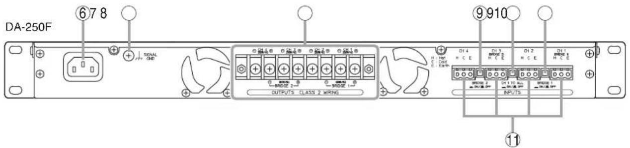
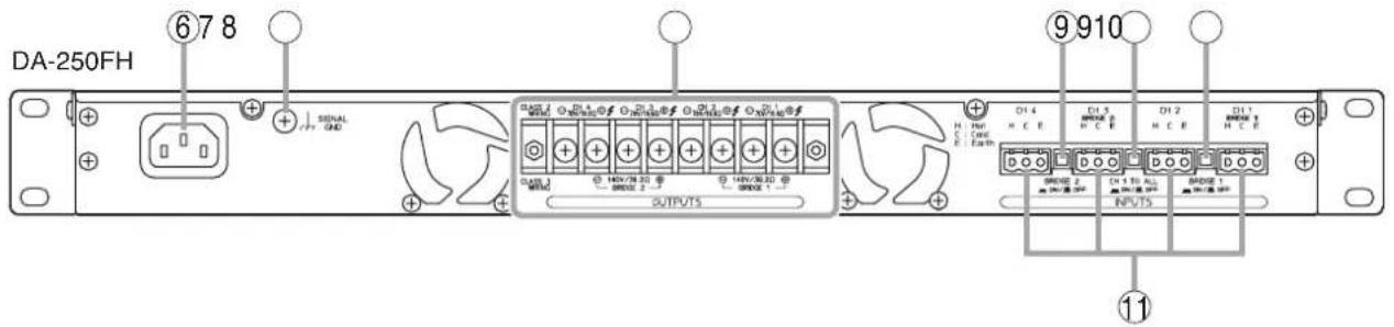
6. AC inlet
Connect the supplied power cord to this inlet.
The socket-outlet shall be installed near the equipment and the plug (disconnecting device) shall be easily accessible.
7. Functional ground terminal [SIGNAL GND]
Hum noise may be generated when external equipment is connected to the unit. Connecting this terminal to the functional ground terminal of the external equipment may reduce the hum noise.
Note
This terminal is not for protective ground.
8. Speaker output terminals (with a terminal cover)
Connect speaker cables to these terminals.
9. BRIDGE ON/OFF switches
[BRIDGE 1, BRIDGE 2, ON / OFF]
Used when bridge-connecting the unit's Channels 1 and 2, and Channels 3 and 4.
(See p. 10; Settings and Connections.)
- 4-channel output mode Set both BRIDGE 1 and 2 switches to OFF. (factory-preset)
- 3-channel output mode Set either BRIDGE 1 or 2 switches to ON. When bridge-connecting Channels 1 and 2, set BRIDGE 1 switches to ON, and BRIDGE 2 switches to ON when bridge-connecting Channels 3 and 4.
- 2-channel output mode Set both BRIDGE 1 and 2 switches to ON.
Note
Be sure to first turn off the Power switch (1) when changing these switch settings.
10. CH1 mode ON/OFF switch
[CH 1 TO ALL, ON/OFF]
Setting this switch to ON transmits the Channel 1 input signal to all channels. (CH1 to All ch mode) Note that output signal levels can be individually adjusted with each channel's Input level control (3).
Setting this switch to OFF (factory-preset) transmits each channel's input signal to each corresponding channel. (Each ch mode)
Note
Be sure to first turn off the Power switch (1) when changing this switch setting.
11. Input terminals [INPUTS]
Electronically-balanced inputs of 3-pin removable terminal block type.
(H: Hot, C: Cold, E: Earth)
8. SETTINGS AND CONNECTIONS
![[Rear panel] CH 1 mode ON/OFF switch BRIDGE 1 ON/OFF switchBRIDGE 2 ON/ Speaker output terminals (with a terminal cover) Input terminals](/content/2026/06/1249356/images/6d3723b0d476db6950ec836bf271becdf7d898902a3edaa62c1f5f734052d7c2.jpg)
Note: The figure shows the DA-250F.
Step 1. Turn off this unit's Power switch.
Step 2. Set the BRIDGE ON/OFF switches and CH 1 mode ON/OFF switch.
Step 3. Connect the sound source equipment to the Input terminals.
Note: Refer to p. 12 for the removable terminal plug connection.
Step 4. Connect speakers to the Speaker output terminals.
4-1. Unscrew the output terminal cover.
4-2. Strip 10 mm (0.39") of insulative jacket from the end of the speaker cable, as shown in the figure at right.
4-3. Connect speaker cables to the output terminals.
4-4. Replace the output terminal cover in place.


WARNING
Be sure to replace the unit's terminal cover after connection completion. Because high voltage is generated at the speaker output terminals, never touch these terminals to avoid electric shock. (DA-250FH only)
8.1. Switch Settings and Speaker Connections
[4 inputs - 4 outputs] (factory-preset)

| Switch | Setting |
| BRIDGE 1 | OFF |
| BRIDGE 2 | OFF |
| CH 1 mode | OFF |
Speaker output terminals

[1 input - 4 outputs]
![graph TD CH1 --> CH11["Ch1"] CH1 --> CH2["Ch2"] CH1 --> CH3["Ch3"] CH1 --> CH4["Ch4"] CH2 --> CH3 CH3 --> CH4 CH4 --> Output1["Output"] CH11 --> A1["A1"] CH2 --> A2["A2"] CH3 --> A3["A3"] CH4 --> A4["A4"]](/content/2026/06/1249356/images/fe66daa4ff9146bf463b3ecd97a389ace3316974b96595fe969c2d2e8ed66a28.jpg)
| Switch | Setting |
| BRIDGE 1 | OFF |
| BRIDGE 2 | OFF |
| CH 1 mode | ON |
Speaker output terminals

[2 inputs - 2 outputs]
![graph TD CH1 --> A["Switch"] CH1 --> B["Ch1 Block"] CH1 --> C["Ch2 Block"] CH1 --> D["Speaker"] CH2 --> E["Switch"] CH2 --> F["Ch2 Block"] CH2 --> G["Ch3 Block"] CH2 --> H["Ch4 Block"] CH3 --> I["Switch"] CH3 --> J["Ch3 Block"] CH3 --> K["Ch4 Block"] CH4 --> L["Switch"] CH4 --> M["Ch4 Block"]](/content/2026/06/1249356/images/ebca23b6d86065aef177622b7b615ec261201d805783694b1bc2f53a69f0e553.jpg)
| Switch | Setting |
| BRIDGE 1 | ON |
| BRIDGE 2 | ON |
| CH 1 mode | OFF |
Speaker output terminals

[1 input - 2 outputs]

| Switch | Setting |
| BRIDGE 1 | ON |
| BRIDGE 2 | ON |
| CH 1 mode | ON |
Speaker output terminals

[3 inputs - 3 outputs (1)]

| Switch | Setting |
| BRIDGE 1 | OFF |
| BRIDGE 2 | ON |
| CH 1 mode | OFF |
Speaker output terminals

[3 inputs - 3 outputs (2)]

| Switch | Setting |
| BRIDGE 1 | ON |
| BRIDGE 2 | OFF |
| CH 1 mode | OFF |
Speaker output terminals

[1 input - 3 outputs (1)]

| Switch | Setting |
| BRIDGE 1 | OFF |
| BRIDGE 2 | ON |
| CH 1 mode | ON |
Speaker output terminals

[1 input - 3 outputs (2)]

| Switch | Setting |
| BRIDGE 1 | ON |
| BRIDGE 2 | OFF |
| CH 1 mode | ON |
Speaker output terminals

9. REMOVABLE TERMINAL PLUG CONNECTION
Cautions
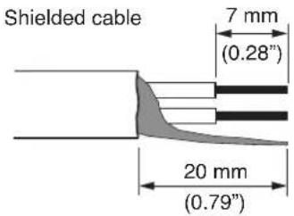
- Be sure to use shielded cables for audio signal lines.
- Avoid soldering cable conductor, as contact resistance may increase when the cable is tightened and the solder is crushed, possibly resulting in an excessive rise in joint temperatures.
- Use cables of AWG 12 – 24.
Cable end treatment
Connector connections
Step 1. Loosen the terminal screw, then insert the cable.
Step 2. Retighten the terminal screw. (Pull on the cable to ensure it is securely connected.)

Tip
Recommended slotted screwdriver type: Screwdriver with blade that is 3 mm (0.12") in width

10. INPUT SENSITIVITY AND HIGH-PASS FILTER ON/OFF SETTINGS
The Input sensitivity can be set to +4 dB (factory-preset) or -10 dB for each channel.
Besides, only the DA-250FH employs the High-pass filter on each channel, which can be set to "ON" or "OFF."
CAUTION
These servicing instructions are for use by qualified personnel only. To avoid electric shock, do not perform any servicing other than that contained in the operating instructions unless you are qualified to do so. Refer all servicing to qualified service personnel.
Step 1. Remove this unit's power plug from an AC outlet.
Step 2. Unscrew 8 screws securing the top cover of the unit, then detach it.
Step 3. Change the jumper socket position to "+4 dB" or "-10 dB" for the Input sensitivity as illustrated below.
When a bridge connection is made;
Set the input sensitivity with the CH1 jumper socket when Channels 1 and 2 are bridge-connected. Similarly, set the input sensitivity with the CH3 jumper socket when Channels 3 and 4 are bridge-connected. (Input sensitivity settings for the CH2 and CH4 are disabled.)
![Input sensitivity setting [When set to +4 dB] (Factory-preset) Jumper socket -10 dB/+4 dB Input Sensitivity [When set to -10 dB] Jumper socket -10 dB/+4 dB Input Sensitivity 2 Viewed from top with the top cover detached. Front panel CH1 CH2 CH3 CH4 3 High-pass filter setting (DA-250FH only) [When se…](/content/2026/06/1249356/images/2e835ce06904e9f3b985b96cca5964c91b241ef9e7c3edbb0e99a1984afb8d3d.jpg)
Step 4. Change the jumper socket position to "ON" or "OFF" for the High-pass filter as illustrated above. (DA-250FH only)
ON position: High-pass filter ON (-12 dB/oct, cut off frequency 50 Hz)
OFF position: High-pass filter OFF

CAUTION
With the High-pass filter jumper socket kept to the OFF position (factory preset), operating the unit for long periods of time while the Peak indicator is illuminated due to excessive input signal may damage the connected speakers, possibly resulting in fire.
Operating the unit with the High-pass filter jumper socket set to the ON position may decrease the possibility of speaker damage or fire due to excessive input signal.
When a bridge connection is made;
Perform the same setting for the channels to be used (Channels 1 and 2, or Channels 3 and 4).
Operating the unit with the different setting may cause unit failure.
Step 5. Replace the detached top cover.
11. PROTECTION OPERATION LIST
| Failure Protection | Operation Indicator Remedy Recovery | |||
| Overcurrent due to overload | Current limiter activated when impedance drops below the specified value. | Peak indicator lights. | Remove overload. | Connecting a correct load automatically restores normal operation. |
| Short circuit Current limiter activated.Load is disconnected. | Protection indicator lights. | Check speakers and lines for short circuit. | Turn off this unit's Power switch. Correct the load, then turn on the power. | |
| Temperature rise at power amp.heat sink (over 110°C or 230°F) | Load disconnected. Protection indicator lights. | Check the unit for correct ventilation and overload. | Operation automatically returns to normal when the temperature decreases. | |
| Temperature rise inside the unit (over 80°C or 176°F) | Built-in amplifier unit that caused the failure halted. | Four indicators of the corresponding channel extinguish. | ||
| Abnormal DC voltage output | Load disconnected. Protection indicator lights. | Contact the TOA dealer where the unit was purchased. | ||
12. TAMPER-PROOF CAP ATTACHMENT
To protect the input level control from accidental operation, it is recommended to replace the control knob with the supplied tamper-proof cap as illustrated.

Tamper-proof cap (accessory)
13. CLEANING THE FILTER
Step 1. Turn off this unit's Power switch.
Step 2. Remove the ventilation panel as shown in the figure.
Step 3. Detach the filter inside the ventilation panel.
Step 4. Clear the filter of dust.
Step 5. Replace the filter and ventilation panel.

14. BLOCK DIAGRAMS
14.1. DA-250F
![graph TD subgraph CH1_INPUT A["CH1 INPUT"] --> B["CH1"] B --> C["CH1"] C --> D["CH2 INPUT"] D --> E["CH2"] E --> F["CH3 INPUT"] F --> G["CH3"] G --> H["CH4 INPUT"] H --> I["CH4"] end subgraph CH1_Sensitivity_Jumper J["CH1 sensitivity selection jumper (+4 dB/-10 dB)"] --> K["+4 dB"] K --> L["-10 dB"]…](/content/2026/06/1249356/images/fc2c71669238f681df94209cc2ee1c2e071fdfdf574070ffa6c542c9edc45c9f.jpg)
![graph TD subgraph CH1_INPUT A["CH E"] B["CH 1 INPUT"] C["CH 2 INPUT"] D["CH 3 INPUT"] E["CH 4 INPUT"] end subgraph CH1-level_control F["CH 1 input level control"] --> G["+4 dB -10 dB"] H["CH 2 input level control"] --> I["+4 dB -10 dB"] J["CH 3 input level control"] --> K["+4 dB -10 dB"] L["CH 4 inp…](/content/2026/06/1249356/images/3d6a21eb0bc45b15888d0a7d04246481f74374904fc36d4d4b595f706c639897.jpg)
15. DIMENSIONAL DIAGRAM
Unit: mm (inches)

16. SPECIFICATIONS
16.1. DA-250F CU
| Power Source | 120 V AC, 50/60 Hz |
| Amplification system | Class D |
| Power Consumption | 200 W (based on UL/CSA standards)1300 W (rated output 4 Ω x 4)850 W (rated output 8 Ω x 4) |
| Input | 4 circuits, +4 dB* (1.23 V, input level control in maximum position),10 kΩ, electronically-balanced, removable terminal block (3 pins)CH 1 mode ON/OFF switch (ON: CH 1 to All ch, OFF: Each ch) |
| Rated Output | 4 channels: 250 W x 4 (4 Ω), 170 W x 4 (8 Ω)2 channels (BRIDGE): 500 W x 2 (8 Ω)M4 screw terminal, distance between barriers: 8.8 mm (0.35") |
| Frequency Response | 20 – 20,000 Hz (±1 dB) |
| Total Harmonic Distortion | 0.1% (1 kHz), 0.3% (20 – 20,000 Hz) |
| Protection Circuit | Protection against excessive current flow due to overload,short circuit, unusual DC voltage output,temperature rise at power amp. heat sink (over 110°C or 230°F),temperature rise inside the unit (over 80°C or 176°F) |
| S/N Ratio | 100 dB (A-weighted) |
| Crosstalk | 70 dB (A-weighted) |
| LED Indicator | Power (blue) x 1, Input (green) x 4, Output (yellow) x 4, Peak (red) x 4,Protect (red) x 4 |
| Cooling | Forced air cooling |
| Operating Temperature | -10°C to +40°C (14°F to 104°F) |
| Operating Humidity | Under 90% RH (no condensation) |
| Finish | Panel: Aluminum, black, alumiteCase: Plated steel sheet |
| Dimensions | 482. (w) x 44 (h) x 401.8 (d) mm (18.98" x 1.73" x 15.82") |
| Weight | 6.6 kg (14.55 lb) |
* 0 dB = 0.775 V
Note: The design and specifications are subject to change without notice for improvement.
- Accessories
Power cord (2 m or 6.56 ft) .... 1
Removable terminal plug (3 pins) 4
Tamper-proof cap 4
16.2. DA-250FH CU
| Power Source | 120 V AC, 50/60 Hz |
| Amplification system | Class D |
| Power Consumption | 200 W (based on UL/CSA standards)1200 W (rated output 70 V line, 19.6 Ω x 4) |
| Input | 4 circuits, +4 dB* (1.23 V, input level control in maximum position),10 kΩ, electronically-balanced, removable terminal block (3 pins)CH 1 mode ON/OFF switch (ON: CH 1 to All ch, OFF: Each ch) |
| Rated Output | 4 channels: 250 W x 4 (70 V line, 19.6 Ω)2 channels (BRIDGE): 500 W x 2 (140 V line, 39.2 Ω)M4 screw terminal, distance between barriers: 8.8 mm (0.35") |
| Frequency Response | 20 – 20,000 Hz (±1 dB): HPF OFF50 – 20,000 Hz (-3 dB, +1 dB): HPF ON(selectable with the inner jumper) |
| Total Harmonic Distortion | 0.1% (1 kHz), 0.3% (20 – 20,000 Hz): HPF OFF0.1% (1 kHz), 0.3% (100 – 20,000 Hz): HPF ON |
| Protection Circuit | Protection against excessive current flow due to overload,short circuit, unusual DC voltage output,temperature rise at power amp. heat sink (over 110°C or 230°F),temperature rise inside the unit (over 80°C or 176°F) |
| S/N Ratio | 100 dB (A-weighted) |
| Crosstalk | 70 dB (A-weighted) |
| LED Indicator | Power (blue) x 1, Input (green) x 4, Output (yellow) x 4, Peak (red) x 4,Protect (red) x 4 |
| Cooling | Forced air cooling |
| Operating Temperature | -10°C to +40°C (14°F to 104°F) |
| Operating Humidity | Under 90% RH (no condensation) |
| Finish | Panel: Aluminum, black, alumiteCase: Plated steel sheet |
| Dimensions | 482. (w) x 44 (h) x 401.8 (d) mm (18.98" x 1.73" x 15.82") |
| Weight | 6.6 kg (14.55 lb) |
* 0 dB = 0.775 V
Note: The design and specifications are subject to change without notice for improvement.
- Accessories
Power cord (2 m or 6.56 ft) .... 1
Removable terminal plug (3 pins) 4
Tamper-proof cap 4
- TABLE OF CONTENTS
- IMPORTANT SAFETY INSTRUCTIONS
- FCC REQUIREMENTS
- SAFETY PRECAUTIONS
- SAFETY SYMBOL AND MESSAGE CONVENTIONS
- WARNING
- CAUTION
- WHEN INSTALLING THE UNIT
- WHEN THE UNIT IS IN USE
- GENERAL DESCRIPTION
- FEATURES
- HANDLING PRECAUTIONS
- INSTALLATION PRECAUTIONS
- NOMENCLATURE AND FUNCTIONS
- POWER SWITCH [ON/OFF]
- POWER INDICATOR [POWER]
- INPUT LEVEL CONTROLS
- WHEN A BRIDGE CONNECTION IS MADE
- VENTILATION PANEL (AIR VENT)
- INDICATORS [INPUT, OUTPUT, PEAK, PROTECT]
- INPUT INDICATOR [INPUT]
- OUTPUT INDICATOR [OUTPUT]
- PEAK INDICATOR [PEAK]
- NOTE
- PROTECTION INDICATOR [PROTECT]
- AC INLET
- FUNCTIONAL GROUND TERMINAL [SIGNAL GND]
- SPEAKER OUTPUT TERMINALS (WITH A TERMINAL COVER)
- BRIDGE ON/OFF SWITCHES
- [BRIDGE 1, BRIDGE 2, ON / OFF]
- CH1 MODE ON/OFF SWITCH
- [CH 1 TO ALL, ON/OFF]
- INPUT TERMINALS [INPUTS]
- SETTINGS AND CONNECTIONS
- SWITCH SETTINGS AND SPEAKER CONNECTIONS
- REMOVABLE TERMINAL PLUG CONNECTION
- CAUTIONS
- CONNECTOR CONNECTIONS
- INPUT SENSITIVITY AND HIGH-PASS FILTER ON/OFF SETTINGS
- PROTECTION OPERATION LIST
- TAMPER-PROOF CAP ATTACHMENT
- CLEANING THE FILTER
- BLOCK DIAGRAMS
- DA-250F
- DIMENSIONAL DIAGRAM
- SPECIFICATIONS
- DA-250F CU
- ACCESSORIES
- DA-250FH CU
Brand : TOA
Model : DA-250FH CU
Category : Microphone