PRO3650RH - Fridge Sub-Zero - Free user manual and instructions
Find the device manual for free PRO3650RH Sub-Zero in PDF.
User questions about PRO3650RH Sub-Zero
0 question about this device. Answer the ones you know or ask your own.
Ask a new question about this device
Download the instructions for your Fridge in PDF format for free! Find your manual PRO3650RH - Sub-Zero and take your electronic device back in hand. On this page are published all the documents necessary for the use of your device. PRO3650RH by Sub-Zero.
USER MANUAL PRO3650RH Sub-Zero
PRO Series Refrigeration
Installation Guide
SPECIFICATIONS, INSTALLATION, AND MORE

Contents
3 PRO Series Refrigeration
4 Opening Dimensions
6 Electrical
7 Plumbing
7 Preparation
8 Anti-Tip Bracket
10 Placement
11 Water Line
11 Alignment
13 Completion
Features and specifications are subject to change at any time without notice. Visit subzero.com/specs for the most up-to-date information.
Important Note
To ensure this product is installed and operated as safely and efficiently as possible, take note of the following types of highlighted information throughout this guide:
IMPORTANT NOTE highlights information that is especially important.
CAUTION
Indicates a situation where minor injury or product damage may occur if instructions are not followed.
WARNING
States a hazard that may cause serious injury or death if precautions are not followed.
IMPORTANT NOTE: Throughout this guide, dimensions in parentheses are millimeters unless otherwise specified.
IMPORTANT NOTE: Save these instructions for the local electrical inspector.
Product Information
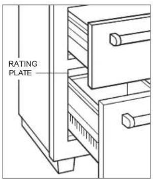
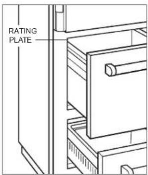
Important product information, including the model and serial number, are listed on the product rating plate. The rating plate is located inside the cabinet, attached to the left interior wall of the bottom drawer for 36" (914) models and the top drawer for 48" (1219) models. Refer to the illustrations below.
If service is necessary, contact Sub-Zero Factory Certified Service with the model and serial number. For the name of the nearest Sub-Zero Factory Certified Service or for questions regarding the installation, visit the Product Support section of our website, subzero.com, or call Sub-Zero Customer Care at 800-222-7820.
text_image
RATING PLATERating plate location—36" models
text_image
RATING PLATERating plate location—48" models
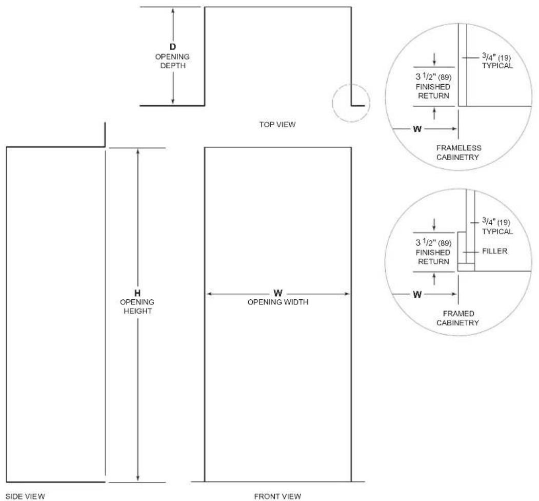
Opening Dimensions
STANDARD | FLUSH INSTALLATION
text_image
D OPENING DEPTH TOP VIEW 3 1/2" (89) FINISHED RETURN 3/4" (19) TYPICAL W FRAMELESS CABINETRY H OPENING HEIGHT W OPENING WIDTH 3 1/2" (89) FINISHED RETURN 3/4" (19) TYPICAL FILLER W FRAMED CABINETRY SIDE VIEW FRONT VIEWNOTE: 3 ^1/2 (69) finished returns will be visible and should be finished to match cabinetry.
STANDARD OPENING
WHD
| 36" Model | 35 12 " (902) | 83 34 " (2127) | 24" (610) |
| 48" Model | 47 12 " (1206) | 83 34 " (2127) | 24" (610) |
For standard installations, the face frame will extend 2" (51) beyond cabinetry.
FLUSH OPENING W H D
| 36" Model | 36" (914) | 84 18 " (2137) | 26" (660) |
| 48" Model | 48" (1219) | 84 18 " (2137) | 26" (660) |
For flush installations, the face frame will be flush with surrounding cabinetry.
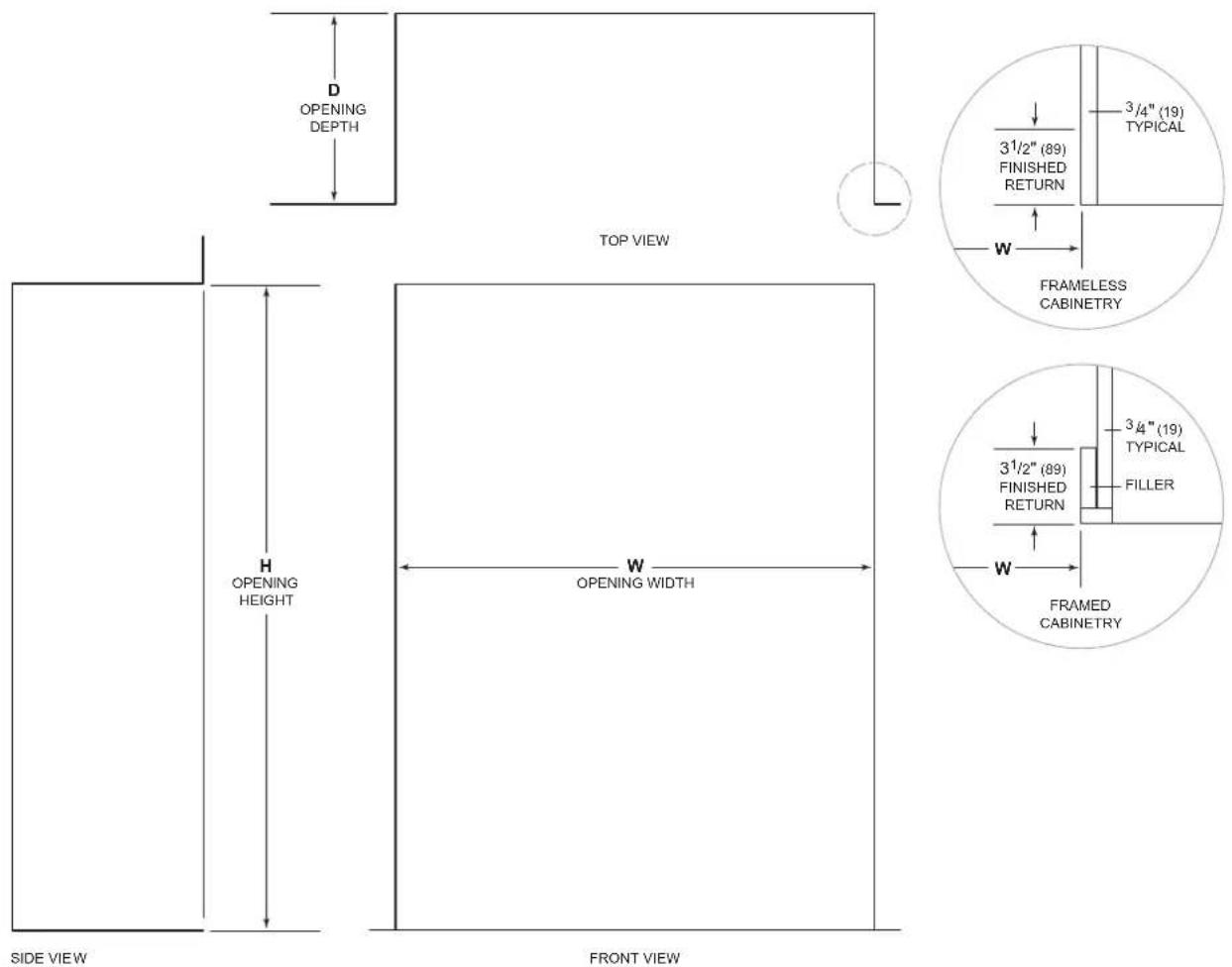
Opening Dimensions
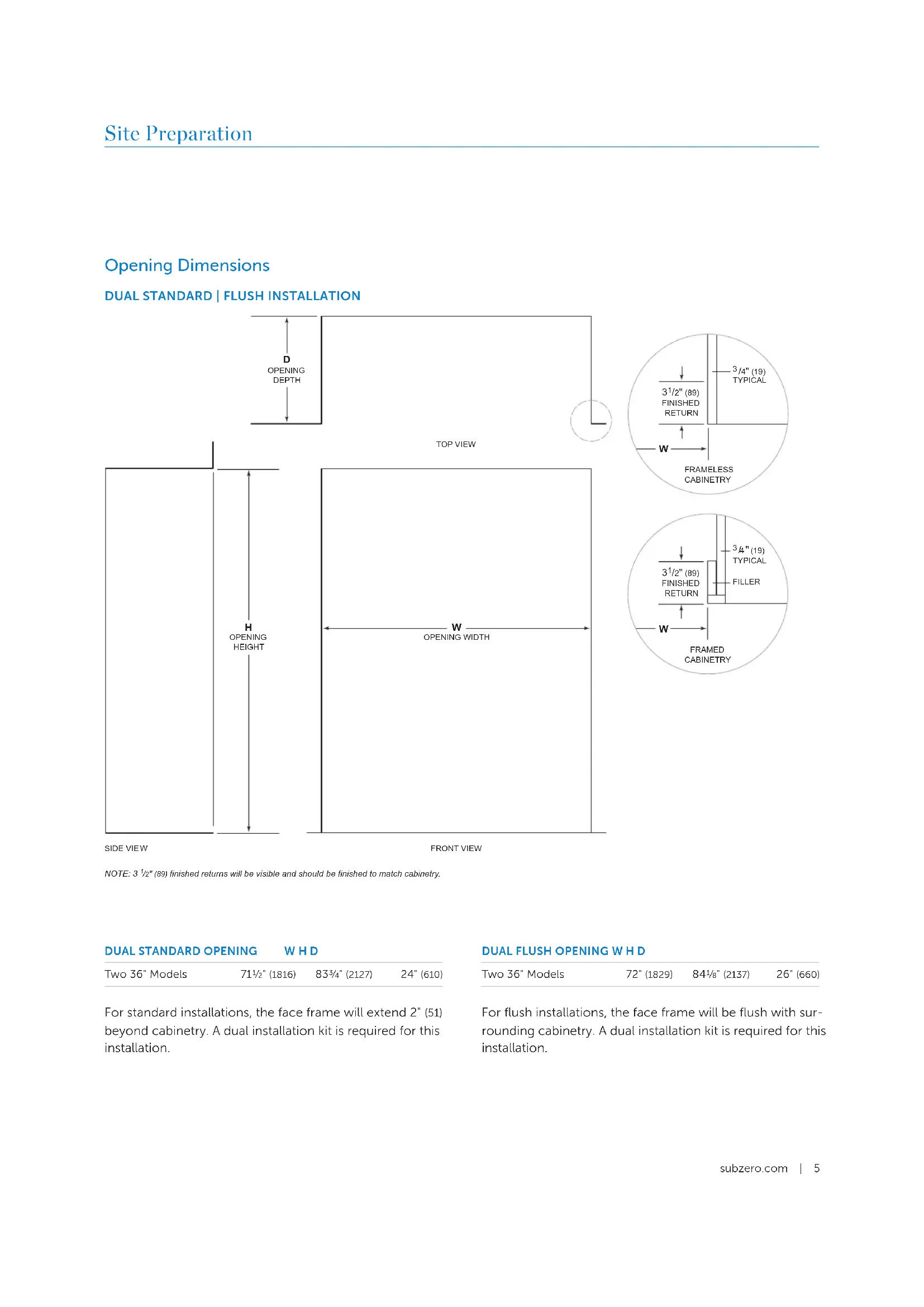
DUAL STANDARD | FLUSH INSTALLATION
text_image
D OPENING DEPTH TOP VIEW 3½" (89) FINISHED RETURN 3/4" (19) TYPICAL W FRAMELESS CABINETRY H OPENING HEIGHT W OPENING WIDTH 3½" (89) FINISHED RETURN 3/4" (19) TYPICAL FILLER W FRAMED CABINETRY SIDE VIEW FRONT VIEWNOTE: 3 ^1/2 (69) finished returns will be visible and should be finished to match cabinetry.
DUAL STANDARD OPENING W H D
| Two 36" Models | 71 12 " (1816) | 83 34 " (2127) | 24" (610) |
For standard installations, the face frame will extend 2" (51) beyond cabinetry. A dual installation kit is required for this installation.
DUAL FLUSH OPENING W H D
| Two 36" Models | 72" (1829) | 84 18 " (2137) | 26" (660) |
For flush installations, the face frame will be flush with surrounding cabinetry. A dual installation kit is required for this installation.
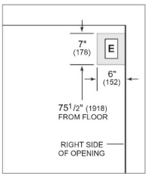
Electrical Requirements
Installation must comply with all applicable electrical codes.
Locate the electrical supply within the shaded area shown in the illustration below. A separate circuit servicing only this appliance is required. A ground fault circuit interrupter (GFCI) is not recommended and may cause interruption of operation.
ELECTRICAL REQUIREMENTS
Electrical Supply 115 VAC, 60 Hz
Service 15 amp dedicated circuit
Receptacle 3-prong grounding-type
text_image
7" (178) E 6" (152) 75½" (1918) FROM FLOOR RIGHT SIDE OF OPENINGElectrical supply location
CAUTION
The outlet must be checked by a qualified electrician to be sure it is wired with the correct polarity. Verify the outlet is properly grounded.
WARNING
If the supply cord is damaged, it must be replaced by the manufacturer, its service agent or similarly qualified persons in order to avoid a hazard.
WARNING
Do not use an extension cord, two-prong adapter, or remove the power cord ground prong.
WARNING
Do not locate multiple portable socket-outlets or portable power supplies at the rear of the appliance.
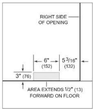
Plumbing Requirements
Installation must comply with all applicable plumbing codes.
Locate the water supply line within the shaded area shown in the illustration below. Connect the water supply line to the house supply with an easily accessible shut-off valve. Do not use self-piercing valves. The water supply line must not interfere with the installation of the anti-tip bracket.
A reverse osmosis system can be used provided there is constant water pressure of 35–120 psi (2.4–8.3 bar) supplied to the unit at all times. In this application, the water filtration system must be bypassed by removing the filter. A copper line is not recommended for this application.
PLUMBING REQUIREMENTS
| Water Supply 1/4" OD copper, braided |
| stainless steel, or PEX tubing |
Pressure 35–120 psi (2.4–8.3 bar)
Excess Line for Connection 36" (914)
text_image
RIGHT SIDE —— OF OPENING 6" 5 3/16" (152) (132) 3" (76) AREA EXTENDS 1/2" (13) FORWARD ON FLOORWater supply location
Preparation
Uncrate the unit, and inspect for damage. Remove the wood base, and discard the shipping bolts and brackets. Remove and recycle packing materials. Do not discard the kickplate, anti-tip bracket, and hardware.
Completely retract the front leveling legs to allow the unit to be moved into position. The front and rear leveling legs can be adjusted from the front once the unit is in position.
Remove the drain pan from the base of the unit to avoid damage and to allow for proper placement of the appliance dolly.
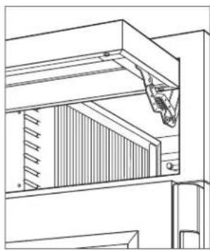
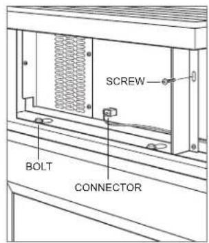
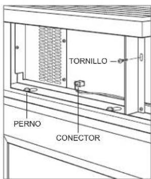
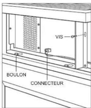
The grille assembly should be removed prior to moving the unit. To remove, rotate the bottom of the grille upward. Disconnect the network cable, then remove the center mounting screw. Loosen the three grille bolts from the grille, then pull the grille forward. Refer to the illustrations below.
natural_image
Architectural line drawing of a window frame structure with diagonal bracing and wall panels (no text or symbols)Lift grille
text_image
SCREW BOLT CONNECTORGrille removal
Preparation
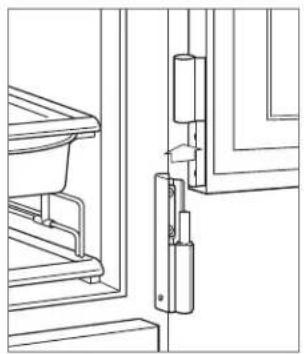
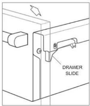
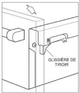
Doors and drawers can be removed for ease of installation. Door and drawer removal is not required. To remove a door, refer to the illustration below. To remove a drawer, pull the drawer out to full-extension. Apply forward pressure to the front of the drawer slide, and pull up and back on the drawer handle. Refer to the illustration below.
natural_image
Technical line drawing of a door frame assembly with no visible text or symbolsDoor removal
text_image
DRAWER SLIDEDrawer removal
Anti-Tip Bracket
WARNING
To prevent the unit from tipping forward, the anti-tip bracket must be installed.
WARNING
To avoid a hazard due to instability of the appliance, it must be fixed in accordance with the instructions.
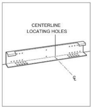
Use the centerline locating holes to position the anti-tip bracket in the center of the opening. The bracket must be positioned 24" (610) from the front of the opening to the back of the bracket. This depth will increase to 26" (660) for a flush installation. Failure to properly position the anti-tip bracket will prevent proper engagement.
text_image
CENTERLINE LOCATING HOLESAnti-tip bracket
Anti-Tip Bracket
Use all anti-tip bracket hardware as instructed for wood or concrete floors.
IMPORTANT NOTE: For wood or concrete floor applications, if the #12 screws do not hit a wall stud or wall plate, use the #8 screws and #12 washers with the wall anchors.
IMPORTANT NOTE: In some installations the subflooring or finished floor may necessitate angling the screws used to fasten the anti-tip bracket to the back wall.
ANTI-TIP HARDWARE
| 1 Anti-tip bracket |
| 12 #12 x 2 12 " pan head screws |
| 3 38 "-16 x 3 34 " wedge anchors |
| 12 #12 flat washers |
| 3 #8-18 x 1 14 " truss head screws |
| 3 Nylon Zip-it® wall anchors |
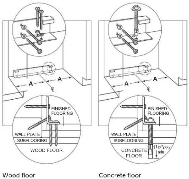
WOOD FLOOR APPLICATION
After properly locating the anti-tip bracket in the opening, drill pilot holes 316 " (5) diameter maximum in the wall studs or wall plate. Use the #12 screws and washers to secure the bracket. Verify the screws penetrate through the flooring material and into the wall studs or wall plate a minimum of 34 " (19). Refer to the chart and illustration below.
CONCRETE FLOOR APPLICATION
After properly locating the anti-tip bracket in the opening, drill pilot holes 316 " (5) diameter maximum in the wall studs or wall plate. Drill 38 " (10) diameter holes into the concrete a minimum of 112 " (38) deep. Use the #12 screws and washers to secure the bracket to the wall, and use the 38 " wedge anchors to secure the bracket to the floor. Verify the screws penetrate the wall studs or wall plate a minimum of 34 " (19). Refer to the chart and illustration below.
ANTI-TIP BRACKET PLACEMENT A
| 36" Model 17 34 " (451) |
| 48" Model 23 34 " (603) |
Anti-Tip Bracket
CONCRETE WEDGE ANCHOR INSTALLATION
1 Drill a 38 " (10) diameter hole any depth exceeding the minimum embedment. Clean the hole or drill additional depth to accommodate the drill fines.
2 Assemble the washer and nut flush with the end of anchor to protect threads. Drive the anchor through the material to be fastened until the washer is flush with the surface material.
3 Expand the anchor by tightening the nut 3–5 turns past hand-tight position or to 25 foot-pounds of torque.
WARNING
Verify there are no electrical wires or plumbing in the area which the screws could penetrate.
CAUTION
Always wear safety glasses and use other necessary protective devices or apparel when installing or working with anchors.
Anchors are not recommended for use in lightweight masonry material such as block or brick, or for use in new concrete which has not had sufficient time to cure. The use of core drills is not recommended to drill holes for the anchors.
Placement
CAUTION
Before moving the unit into position, secure doors and drawers closed, and protect any finished flooring.
Use an appliance dolly to move the unit near the opening.
If the unit has been on its back or side, it must stand upright for a minimum of 24 hours before connecting power.
Plug the power cord into the grounded outlet, and roll the unit into position. Verify the anti-tip bracket is properly engaged.
WARNING
When positioning the appliance, ensure the supply cord is not trapped or damaged.
Water Line
Approximately 3' (.9 m) of 14 " plastic tubing is connected to the unit with a preassembled 14 " compression connection under the unit. The water line fitting connection kit, provided with the unit, contains a 14 " compression union fitting for connection to the household water line.
Purge the water line prior to final connection to the unit. This will remove any debris that may be present in the tubing from installing the new water line.
Place the sleeve and nut on the water line, and fasten to the connection at the end of the tubing. Do not over tighten. Check all water line fittings for leaks. Verify the drain pan can be installed and removed without interference with the water line.
IMPORTANT NOTE: If a reverse osmosis system is used, it is recommended the water filtration system be bypassed by removing the filter.
IMPORTANT NOTE: Water lines cannot be exposed to freezing temperatures.
WARNING
Connect to potable water supply only.
Alignment
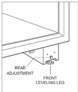
LEVELING
Once the unit is in position, turn the front leveling legs clockwise to adjust the height. The rear height adjustment can be made from the front of the roller base. Using a 38 " socket, turn the 38 " hex bolt clockwise to raise the unit or counterclockwise to lower. Use the lowest torque setting when using a power drill. Do not turn the rear leveling legs by hand. Refer to the illustration below.
When the unit is properly leveled, door and drawer adjustments are less likely to be necessary.
IMPORTANT NOTE: Level the unit to the floor, not the surrounding cabinetry. This could affect the operation of the unit, such as door closing.
WARNING
To reduce the possibility of the unit tipping forward, the front leveling legs must be in contact with the floor.
text_image
REAR ADJUSTMENT FRONT LEVELING LEGLeveling
Alignment
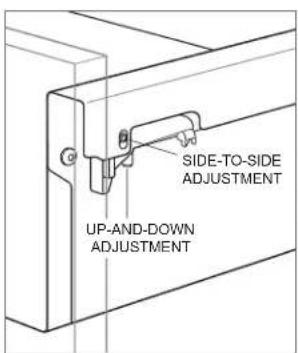
DOOR ADJUSTMENT
The doors are adjustable in and out, up and down, and side to side. In-and-out and up-and-down adjustments are made on the door. Side-to-side adjustments are made on the cabinet hinges. To make any adjustments, remove the door and hinge pins. Refer to the illustration below.
In-and-Out and Up-and-Down Adjustment:
1 Place the door on a protected work surface, then loosen the two upper hinge mounting screws.
2 Remove the two lower hinge mounting screws, then remove the lower hinge.
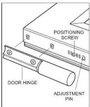
3 Remove the positioning screw from the bottom of the door, then use the adjustment pin to make up-and-down and in-and-out adjustments. Refer to the illustration below. Each vertical hole location adjusts the door 132 " (1). The slotted holes allow for in-and-out adjustment.
4 Once the adjustments are made, install and tighten the positioning screw.

text_image
HINGE PINDoor removal
text_image
POSITIONING SCREW DOOR HINGE ADJUSTMENT PINDoor adjustment
Side-to-Side Adjustment:
1 Loosen the two mounting screws on the upper and/or lower cabinet hinge. Refer to the illustration below.
2 Use an Allen wrench to rotate the adjustment screw.
3 Verify the hinge is parallel to the side of the unit, then tighten the mounting screws.
4 Install the hinge pins and door, then verify the door alignment.

text_image
HINGE SCREW ADJUSTMENT SCREWCabinet hinge adjustment
Alignment
DRAWER ADJUSTMENT
Up-and-Down Adjustment:
1 Use a hex wrench to turn the up-and-down adjustment screw counterclockwise to raise and clockwise to lower. Refer to the illustration below.
Side-to-Side Adjustment:
1 Use a hex wrench to turn the adjustment screw. Refer to the illustration below.
2 Both drawer slides must be adjusted equally to achieve movement. For example, if the right slide adjustment screw rotated clockwise, rotate the left slide screw equally counterclockwise.
Tilt Adjustment:
1 Loosen the side and the bottom, center screws. Refer to the illustration below.
2 Remove the screw from the corner of the drawer that is out of adjustment.
3 Move the drawer front in or out by hand.
4 Install the screw into the bottom of the drawer. Each hole location adjusts the door in or out by 132 " (1).
5 Tighten the side and bottom, center screws.
text_image
SIDE-TO-SIDE ADJUSTMENT UP-AND-DOWN ADJUSTMENTDrawer adjustment

text_image
LOOSEN LOOSEN REMOVEDrawer tilt adjustment
Completion
ANCHORING
After the unit has been leveled and door and drawer adjustment completed, anchor the unit to the opening to ensure a proper fit and secure installation.
To Anchor the Unit:
1 Loosen the mounting bracket screws at the top of the unit, then slide the mounting brackets to the side until they contact the sides of the opening. Install additional blocking if necessary. Refer to the illustration below.
2 Secure the brackets with the anchoring screws provided, then tighten the mounting bracket screws.

text_image
ANCHORING SCREWS BRACKET SCREWSAnchoring
Completion
Install the grille assembly and check for proper fit. Reconnect the network cable. Refer to page 7. Attach the network cable to the grille using the cable ties provided.
Reinstall the drain pan and verify it is in the proper position.
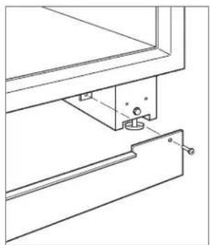
Install the kickplate using the screws to attach it to the brackets on the inside of each roller base. Refer to the illustration below. The kickplate must be removable for service. The floor cannot interfere with removal.
Install the leg covers.
For initial start up, touch and hold Ⓐ POWER on either external touch display, located on the grille.
natural_image
Technical line drawing of a mechanical assembly with mounting bracket and bracket (no text or symbols)Kickplate installation
WATER FILTER BYPASS
If the water filtration system will not be used, it can be bypassed by removing the water filter.
To Remove the Water Filter:
1 To access the water filter, rotate the bottom of the grille upward.
2 To remove the filter, rotate counterclockwise one-quarter turn, then pull out. Refer to the illustration below.
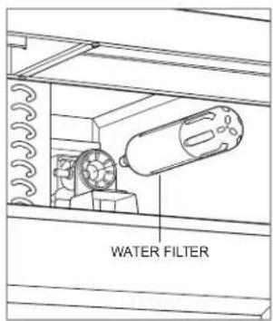
text_image
WATER FILTERWater filter removal
Completion
90° DOOR STOP
The door(s) of all models open to 135°. For installations where the door opening must be limited, an optional 90° door stop kit is available through an authorized Sub-Zero dealer. For local dealer information, visit the find a showroom section of our website, subzero.com.
WARNING
Follow all city and state laws when storing, recycling, or discarding unused refrigerators and freezers.
Sub-Zero, Sub-Zero & Design, Sub-Zero & Snowflake Design, Dual Refrigeration, The Living Kitchen, Great American Kitchens The Fine Art of Kitchen Design, Wolf, Wolf & Design, Wolf Gourmet, W & Design, red colored knobs, Cove, and Cove & Design are registered trademarks and service marks of Sub-Zero Group, Inc. and its subsidiaries. All other trademarks are property of their respective owners in the United States and other countries.
Contenido
natural_image
Architectural line drawing of a window frame with wooden beams and a hanging object (no text or symbols)Levante la rejilla
text_image
TORNILLO PERNO CONECTORnatural_image
Technical line drawing of a door frame assembly with no visible text or symbolstext_image
AFLOJAR AFLOJAR RETIRARnatural_image
Technical line drawing of a mechanical assembly with mounting bracket and bracket (no text or symbols)natural_image
Architectural line drawing of a cabinet or shelf with structural ribs and a door, showing no text or symbols.Grille de gauche
text_image
VIS BOULON CONNECTEURnatural_image
Technical line drawing of a door frame assembly with no visible text or symbolsRetrait de la porte
text_image
GLISSIÈRE DE TIROIRRetrait du tiroir
Support antibasculement
AVERTISSEMENT
natural_image
Technical line drawing of a mechanical assembly with mounting bracket and bracket (no text or symbols)Installation de la plaque de protection