
3714 - Measuring tool MILWAUKEE - Free user manual and instructions
Find the device manual for free 3714 MILWAUKEE in PDF.
User questions about 3714 MILWAUKEE
0 question about this device. Answer the ones you know or ask your own.
Ask a new question about this device
Download the instructions for your Measuring tool in PDF format for free! Find your manual 3714 - MILWAUKEE and take your electronic device back in hand. On this page are published all the documents necessary for the use of your device. 3714 by MILWAUKEE.
USER MANUAL 3714 MILWAUKEE
natural_image
Technical line drawing of a mechanical device with no visible text or symbolsCat. No. / No de Cat.
3714
DUAL SLOPE ROTARY LASER RECEIVER RÉCEPTEUR DE LASER ROTATIF DOUBLE PENTE RECEPTOR DE LÁSER GIRATORIO DE DOBLE PENDIENTE

WARNING To reduce the risk of injury, user must read and understand operator's manual.
Read and understand all instructions. Failure to follow all instructions
listed below, may result in electric shock, fire and/or serious personal injury. Save all warnings and instructions for future reference.
- Save these instructions - This operator's manual contains important safety and operating instructions.
WORK AREA SAFETY
- Ensure adequate safeguards at the work site (e.g., surveying site when measuring on roads, construction sites, etc.).
- Avoid dangerous environments. Avoid extended exposure to rain, snow, damp or wet locations. Do not use in the presence of explosive atmospheres (gaseous fumes, dust or flammable materials).
PERSONAL SAFETY
- Do not allow persons unfamiliar with the tool, these safety instructions, and the tool's operator's manual to operate the tool. This tool can be dangerous in the hands of untrained users.
- Do not overreach. Keep proper footing and balance at all times. This enables better control of the tool in unexpected situations.
BATTERY USE AND CARE
WARNING
Read and understand all instructions. Failure to follow all instruc-
tions may result in electric shock, fire and/c serious personal injury. Save these instructions.
- This tool is designed to be powered by AA batteries properly inserted into the tool. Do not attempt to use with any other voltage or power supply. Do not use zinc-carbon batteries.
- Chemical Burn Hazard. A new or used battery can cause severe internal burns and lead to death in as little as 2 hours if swallowed or enters the body. Keep away from children. If you think batteries may have been swallowed or entered the body, seek immediate medical attention.
- Do not mix new and used batteries. Do not mix brands (or types within brands) of batteries.
- Do not mix rechargeable and non-rechargeable batteries.
- Install batteries according to polarity (+/- diagrams. Do not install batteries backwards. Batteries can explode or leak.
- Do not crush, drop, damage, or expose batteries to high temperature. Under abusive conditions, liquid may be ejected from the battery, avoid contact. If contact accidentally occurs, flush with water. If liquid contacts eyes, additionally seek medical help.
- Do not incinerate or dismantle batteries. Properly dispose of used batteries immediately.
SPECIFIC SAFETY RULES FOR ROTARY LASER RECEIVER
- The device conforms to the most stringent requirements of the relevant Electromagnetic Compatibility (EMC) Standards and Regulations. Yet, the possibility of causing interference in other devices cannot be totally excluded.
CAUTION
Use of controls or adjustments or performance of procedures other
than those specified herein may result in hazardous radiation exposure.
- Be sure to power off instrument after use. When instrument will not be used for a long period, place it in storage after removing batteries. - Watch out for erroneous results if the tool is defective or if it has been dropped, misused or modified. - Do not dispose of tool or batteries together with household waste material! Tool and batteries that have reached the end of their life must be collected separately and returned to an environmentally compatible recycling facility.
Always use common sense and be cautious when using tools. It is not possible to anticipate every situation that could result in a dangerous outcome. Do not use this tool if you do not understand these operating instructions or you feel the work is beyond your capability; contact Milwaukee Tool or a trained professional for additional information or training.
- Maintain labels and nameplates. These carry important information. If unreadable or missing, contact a MILWAUKEE service facility for a free replacement.
FC
Federal Communications Commission
Pursuant to part 15.21 of the FCC Rules, you are cautioned that changes or modifications not expressly approved by the party responsible for compliance could void your authority to operate the product.
This equipment has been tested and found to comply with the limits for a Class B digital device, pursuant to Part 15 of the FCC Rules. These limits are designed to provide reasonable protection against harmful interference in a residential installation. This equipment generates, uses and can radiate radio frequency energy and, if not installed and used in accordance with the instructions, may cause harmful interference to radio communications. However, there is no guarantee that interference will not occur in a particular installation. If this equipment does cause harmful interference to radio or television reception, which can be determined by turning the equipment off and on, the user is encouraged to try to correct the interference by one or more of the following measures:
- Reorient or relocate the receiving antenna.
- Increase the separation between the equipment and receiver.
- Connect the equipment into an outlet on a circuit different from that to which the receiver is connected.
- Consult the dealer or an experienced radio/TV technician for help.
This device complies with part 15 of the FCC Rules and ISED-Canada's license exempt RSS standards. Operation is subject to the following two conditions: 1) This device may not cause harmful interference, and 2) This device must accept any interference received, including interference that may cause undesired operation.
CAT. NO. 3714
3 V= AAx2 LR6/15A
SER.
Contains FCC ID: SQGBL654
Contains IC: 3147A-BL654

DUAL SLOPE ROTARY LASER RECEIVER
Milwaukee Tool, Brookfield, WI 53005 USA
This device complies with part 15 of the FCC Rules.
Operation is subject to the following two conditions:
-
This device may not cause harmful interference.
-
This device must accept any interference received, including interference that may cause undesired operation

text_image
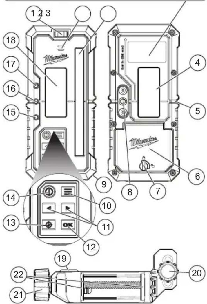
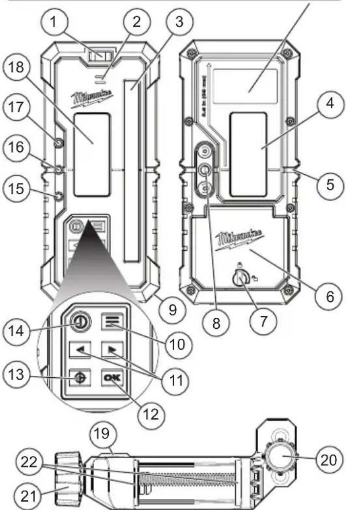
Technical diagram of a device with numbered components and labeled parts, including a zoomed-in view of the internal panel.-
Bubble Level
-
Speaker
-
Sensor
-
Back LCD screen
-
Center line
-
Battery door
-
Battery door turn lock
-
Clamp connection feature
-
Wrist strap attachment
-
Menu button
-
Arrow buttons
-
OK button
-
Grade match button
-
Power button
-
High indicator LED
-
Center indicator LED
-
Low indicator LED
-
Front LCD screen
-
Surface vial
-
Clamp attachment knob
-
Clamping knob
-
Clamp jaws
VoltsV

Direct Current

Read Operator's Manual


OK Button

Lock

Unlock
SPECIFICATIONS
Cat. No....3714
Volts....3 V (2xAA) IEC LR6/ANSI 15A
Module/FCC ID......BL654/SQGBL654
Reception Angle 70°
Wavelength Compatibility 620 - 690 nm
Detection Range.... 15' up to 4000'
Receiving Area ±2.4"
Volume≥95 dBa
Altitude....<6560'
Pollution Degree....2
Ingress Protection....IP67
(Battery component not included)
Drop Rating 2 m
Center Indication (From Top).... 3.5"
Auto Shut-off....15 min
(No button presses or laser detection)
Run Time 40 hrs
Clamp Weight....0.4 lbs
Clamp Width 2.5"
Maximum Relative Humidity (RH) 80%
for up to 88°F
Decreasing Linearly Relative Humidity (RH) ..... 50%
at 104^
Recommended Ambient
Storage Temperature ....-13°F to 140°F
Operating Temperature ...... -4°F to 122°F
Recommended Compatible
Laser Cat. No. 3704-20
NOTE: Distance, laser power, and other environmental factors such as temperature, precipitation, or ambient light conditions may negatively impact product accuracy and range.
ASSEMBLY
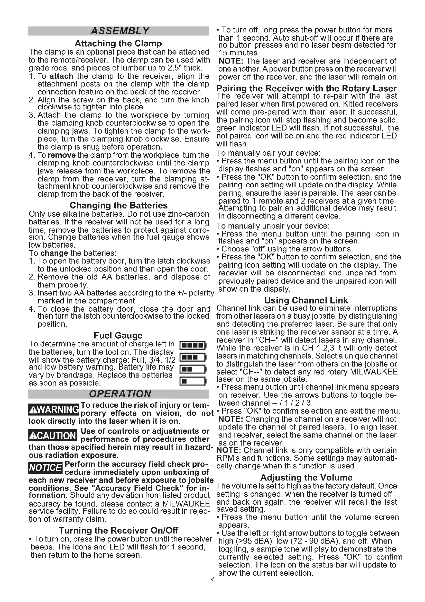
Attaching the Clamp
The clamp is an optional piece that can be attached to the remote/receiver. The clamp can be used with grade rods, and pieces of lumber up to 2.5" thick.
- To attach the clamp to the receiver, align the attachment posts on the clamp with the clamp connection feature on the back of the receiver.
- Align the screw on the back, and turn the knob clockwise to tighten into place.
- Attach the clamp to the workpiece by turning the clamping knob counterclockwise to open the clamping jaws. To tighten the clamp to the workpiece, turn the clamping knob clockwise. Ensure the clamp is snug before operation.
- To remove the clamp from the workpiece, turn the clamping knob counterclockwise until the clamp jaws release from the workpiece. To remove the clamp from the receiver, turn the clamping attachment knob counterclockwise and remove the clamp from the back of the receiver.
Changing the Batteries
Only use alkaline batteries. Do not use zinc-carbon batteries. If the receiver will not be used for a long time, remove the batteries to protect against corrosion. Change batteries when the fuel gauge shows low batteries.
To change the batteries:
- To open the battery door, turn the latch clockwise to the unlocked position and then open the door.
- Remove the old AA batteries, and dispose of them properly.
- Insert two AA batteries according to the +/- polarity marked in the compartment.
- To close the battery door, close the door and then turn the latch counterclockwise to the locked position.
Fuel Gauge
To determine the amount of charge left in the batteries, turn the tool on. The display will show the battery charge: Full, 3/4, 1/2 and low battery warning. Battery life may vary by brand/age. Replace the batteries as soon as possible.
OPERATION
⚠ WARNING To reduce the risk of injury or temporary effects on vision, do not look directly into the laser when it is on.
ACAUTION Use of controls or adjustments or performance of procedures other than those specified herein may result in hazardous radiation exposure.
NOTICE Perform the accuracy field check procedure immediately upon unboxing of each new receiver and before exposure to jobsite conditions. See "Accuracy Field Check" for information. Should any deviation from listed product accuracy be found, please contact a MILWAUKEE service facility. Failure to do so could result in rejection of warranty claim.
Turning the Receiver On/Off
- To turn on, press the power button until the receiver beeps. The icons and LED will flash for 1 second, then return to the home screen.
- To turn off, long press the power button for more than 1 second. Auto shut-off will occur if there are no button presses and no laser beam detected for 15 minutes.
NOTE: The laser and receiver are independent of one another. A power button press on the receiver will power off the receiver, and the laser will remain on.
Pairing the Receiver with the Rotary Laser The receiver will attempt to re-pair with the last paired laser when first powered on. Kitted receivers will come pre-paired with their laser. If successful, the pairing icon will stop flashing and become solid. green indicator LED will flash. If not successful, the not paired icon will be on and the red indicator LED will flash.
To manually pair your device:
- Press the menu button until the pairing icon on the display flashes and "on" appears on the screen.
- Press the "OK" button to confirm selection, and the pairing icon setting will update on the display. While pairing, ensure the laser is pairable. The laser can be paired to 1 remote and 2 receivers at a given time. Attempting to pair an additional device may result in disconnecting a different device.
To manually unpair your device:
- Press the menu button until the pairing icon in flashes and "on" appears on the screen.
- Choose "off" using the arrow buttons.
- Press the "OK" button to confirm selection, and the pairing icon setting will update on the display. The receiver will be disconnected and unpaired from previously paired device and the unpaired icon will show on the dispaly.
Using Channel Link
Channel link can be used to eliminate interruptions from other lasers on a busy jobsite, by distinguishing and detecting the preferred laser. Be sure that only one laser is striking the receiver sensor at a time. A receiver in "CH--" will detect lasers in any channel. While the receiver is in CH 1,2,3 it will only detect lasers in matching channels. Select a unique channel to distinguish the laser from others on the jobsite or select "CH--" to detect any red rotary MILWAUKEE laser on the same jobsite.
- Press menu button until channel link menu appears on receiver. Use the arrows buttons to toggle between channel -- / 1 / 2 / 3.
- Press "OK" to confirm selection and exit the menu.
NOTE: Changing the channel on a receiver will not update the channel of paired lasers. To align laser and receiver, select the same channel on the laser as on the receiver.
NOTE: Channel link is only compatible with certain RPM's and functions. Some settings may automatically change when this function is used.
Adjusting the Volume
The volume is set to high as the factory default. Once setting is changed, when the receiver is turned off and back on again, the receiver will recall the last saved setting.
- Press the menu button until the volume screen appears.
- Use the left or right arrow buttons to toggle between high (>95 dBA), low (72 - 90 dBA), and off. When toggling, a sample tone will play to demonstrate the currently selected setting. Press "OK" to confirm selection. The icon on the status bar will update to show the current selection.
Setting the Units of Measure
- Press the menu button until the units screen appears.
- Choose from the measurement options by using the left or right arrow buttons; millimeters, inches (decimal), inches (fractions), and tenths of feet (decimal) using the arrow buttons.
- Press the "OK" button, and the measurement setting will update in the direct read out.
Setting the Accuracy
- Press the menu button until the accuracy screen appears.
- Choose from the accuracy settings below of: ultra fine, fine, medium, coarse and ultra coarse.
- Press the "OK" button to confirm selection, and the accuracy setting will update in the direct read out.
| Receiver Accuracy | |||||
| mm | in. (Dec.) | in. (Frac.) | ft. | Accuracy Levels(1= Ultra-Fine5= Ultra-Coarse) | Levels |
| 0.5 | 0.02 1/32 | 0.001 Level 1 | |||
| 1 | 0.04 1/16 | 0.003 Level 2 | |||
| 2 | 0.08 1/8 0 | 0.006 Level 3 | |||
| 3 | 0.12 1/4 0 | 0.010 Level 4 | |||
| 5 | 0.2 1/2 0.0 | 16 Level 5 | |||
Center Lock
Center lock feature is only compatible with certain RPM's and accuracy settings and is not compatible with channel link. Some settings may automatically change when this function is being used.
- Place the paired receiver in the desired location.
NOTE: The receiver must be aligned with the X or Y axis of the rotary laser. For best results, use the iron sight on top of the laser to align directly with the receiver sensor. - Press the grade match button on the receiver. Select the center lock (crosshair with lock icon) using the left or right arrow buttons and press the "OK" button to continue.
- Use the arrow keys to select the desired axis. NOTE: Ensure the laser is aligned and in range of the receiver being used.
- The laser will begin to search for the receiver.
- Once the center is found the laser beam will move with the receiver. Up or down indicators and number readout will appear while the laser adjusts in real-time.
NOTE: Ensure to not move the receiver too fast or out of range, this may create an error, and the process will have to be repeated. If not found, the red LED will show on the receiver and "not found" error will appear on the laser/remote. Press the "OK" button, and the laser and remote will go to the main menu, and the laser will start the self-leveling procedure. After the laser is leveled, press the grade match button on the receiver and try steps 1 - 4 again until the center is found.
Grade Match
Grade match is for checking the rise or fall of the ground between two elevations without complex calculations needed. Grade match feature is only compatible with certain RPM's and accuracy settings and is not compatible with channel link. Some settings may automatically change when this function is being used.
- Place the paired receiver in the desired location. NOTE: The receiver must be aligned with the X or Y axis of the rotary laser. For best results, use the iron sight on top of the laser to align directly with the receiver sensor.
- Press the grade match button on the receiver, and press the "OK" button to continue.
- Use the arrow keys to select the desired axis. NOTE: Ensure the laser is aligned and in range of the receiver being used.
- Press the "OK" button to confirm the selection and begin the grade match function. The laser will begin to search for the receiver. Once the laser is detected on the center of the receiver, the direct readout and arrow segments and green indicator LED will flash green to indicate success. The measured grade will be displayed on the laser and remote. If failed, the red indicator LED will flash. Repeat steps above to try again.
Direct Readout and Arrow Indicators
If a laser is sensed, the direct readout, arrow indicators, and indicator LEDs will illuminate to guide the user in moving the receiver to align the laser with the center. If no laser is detected, the LEDs, and arrow indicator will remain off, and the direct readout will show no value and display "- - -".
- High LED indicator (blue) - Move the receiver location up until on center.
- On center LED indicator (green) - The line being detected from the laser is on center.
- Low LED indicator (red) - Move the receiver location down until on center.
NOTE: If the laser leaves the sensor, the up or down arrow segments will begin to cycle, indicating the direction that the laser was last detected.
Other Receiver Modes
- Sleep Icon - Indicates that the laser is asleep and must be woken up before grade match or center lock can be initiated.
- CAL Icon - Will appear on the receiver when laser is using it for calibration.
Troubleshooting
- Ensure batteries are inserted correctly according to the +/- polarity marked in the compartment.
- Replace batteries that may be at the end of life.
- Ensure the tool's internal temperature is within specified operating ranges. If stored in excessive heat or cold, allow at least 2 hours to acclimate to ambient temperature before turning on the tool.
- If the receiver screen pauses for a long period of time, press and hold the power button for 15 seconds or remove the batteries to reset.
- If attempting grade match and both center lock and grade match icons flash at the same time, this is an indication that the function cannot be completed. Check pairing status and review laser for any warnings that must be cleared before proceeding.
Pairing Failure:
- Ensure the receiver is powered on, within the distance range and in pairing mode.
- Avoid artificial overhead lighting on the receiver sensor.
- Avoid the laser projecting a beam onto the receiver sensor during pairing.
- Avoid transmitting devices.
- Place the laser on a stable surface during pairing to prevent interruption from bump alarms. For best results, pair in the horizontal orientation.
- The no connection error may appear on laser if your devices are not paired. Try repeating the pairing steps in the "Pairing the Receiver with the Rotary Laser" section.
If problem persists, please contact an authorized MILWAUKEE service center for support.
ACCURACY FIELD CHECK
NOTICE Perform the accuracy field check procedure immediately upon unboxing of each receiver and before exposure to jobsite conditions. See "Accuracy Field Check" for information. Should any deviation from listed product accuracy be found, please contact an authorized MILWAUKEE service center. Failure to do so could result in rejection of warranty claim.
Influences on Accuracy
Sunlight or other extreme lighting conditions can adversely impact accuracy. For best results, use indoors or avoid direct sunlight. Abusive treatment of the laser level receiver, such as excessive impacts from drops, can lead to deviations in product accuracy. Therefore, it is recommended to conduct the Field Check procedure after any impact or before completing any critical jobs. For best results, use MILWAUKEE Lasers.
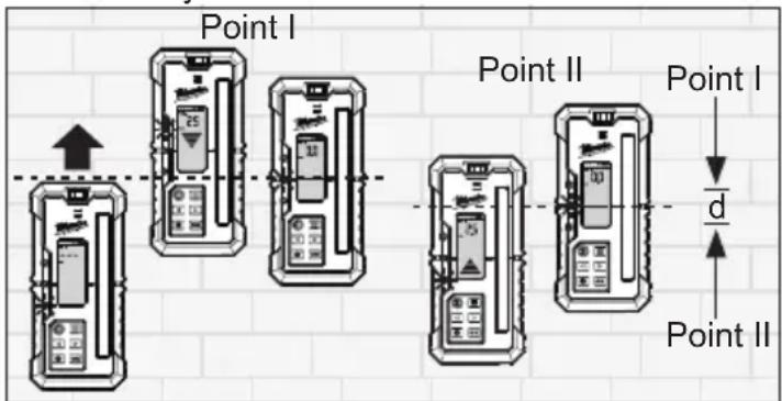
Receiver Accuracy Check Procedure
- Set up a compatible laser 30' using a flat wall.
- Ensure the laser source is self-leveled and perpendicular to the wall.
- Place the receiver flat on a wall directly in front of the laser source and slightly below the projected laser line.
- Keeping the bottom of the receiver parallel with the ground, raise the receiver past the center mark until the down arrow appears on the LCD screen.
- Lower the receiver until the center line appears.
- Mark a line on the wall – Point "I".
- Continue to lower the receiver until the up arrow appears.
- Raise the receiver until the center line appears.
- Mark a line on the wall – Point "II".
- Measure the distance between Point "I" and Point "II" – divide by 2. After completion, compare this to the receiver accuracy table in the "Setting Accuracy" section.
text_image
Point I Point II Point I d/d Point IIMAINTENANCE
⚠ WARNING To reduce the risk of injury, always remove the battery before performing any maintenance. Never disassemble the tool.
Maintain Laser Receiver
Maintain tools. If damaged, have the tool repaired by an authorized MILWAUKEE service center before use. Accidents may be caused by poorly maintained tools.
⚠ WARNING To reduce the risk of personal injury and damage, never immerse your tool in liquid or allow a liquid to flow inside them.
Cleaning
Clean dust and debris from any vents. Keep tool clean, dry and free of oil or grease. Use only mild soap and a damp cloth to clean, since certain cleaning agents and solvents are harmful to plastics and other insulated parts. Some of these include gasoline, turpentine, lacquer thinner, paint thinner, chlorinated cleaning solvents, ammonia and household detergents containing ammonia. Never use flammable or combustible solvents around tools.
Cleaning the Sensor Window
Always wear eye protection. Blow off any loose particles with clean compressed air. Carefully wipe the surface with a cotton swab moistened with water.
Repairs
For repairs, return the tool, battery pack and charger to the nearest authorized service center.
ACCESSORIES
WARNING Use tools only with specifically designated accessories. Use of any other accessories may create risk of injury.
SERVICE - UNITED STATES
1-800-SAWDUST (1.800.729.3878)
Monday-Friday, 7:00 AM - 6:30 PM CST
or visit www.milwaukeetool.com
Contact Corporate After Sales Service Technical Support with technical, service/repair, or warranty questions.
Email: metproductsupport@milwaukeeetool.com
Become a Heavy Duty Club Member at www.milwaukeetool.com to receive important notifications regarding your tool purchases.
SERVICE - CANADA
Milwaukee Tool (Canada) Ltd
1.877.948.2360
Monday-Friday, 7:00 AM - 4:30 PM CST
or visit www.milwaukeeetool.ca
LIMITED WARRANTY USA&CANADA
This MILWAUKEE power tool* is warranted to the original purchaser from an authorized MILWAUKEE distributor only to be free from defects in material and workmanship. Subject to certain exceptions, MILWAUKEE will repair or replace any part on this power tool which, after examination, is determined by MILWAUKEE to be defective in material or workmanship for a period of two (2) years after the date of purchase unless otherwise noted. Return of the power tool to a MILWAUKEE factory Service Center location or MILWAUKEE Authorized Service Station, freight prepaid and insured, is required. A copy of the proof of purchase should be included with the return product. This warranty does not apply to damage that MILWAUKEE determines to be from repairs made or attempted by anyone other than MILWAUKEE authorized personnel, misuse, alterations, abuse, normal wear and tear, lack of maintenance, or accidents.
Normal Wear: Many power tools need periodic parts replacement and service to achieve best performance. This warranty does not cover repair when normal use has exhausted the life of a part including, but not limited to, chucks, brushes, cords, saw shoes, blade clamps, o-rings, seals, bumpers, driver blades, pistons, strikers, lifters, and bumper cover washers. *This warranty does not cover battery packs or all power tools. Refer to the separate and distinct warranties available for those products.
The warranty period for the LED in the LED Work Light (49-24-0171) and the LED Upgrade Bulb (49-81-0090) is the lifetime of the product subject to the limitations above. If during normal use the LED or LED Upgrade Bulb fails, the part will be replaced free of charge.
Warranty Registration is not necessary to obtain the applicable warranty on a MILWAUKEE power tool product. The manufacturing date of the product will be used to determine the warranty period if no proof of purchase is provided at the time warranty service is requested.
ACCEPTANCE OF THE EXCLUSIVE REPAIR AND REPLACEMENT REMEDIES DESCRIBED HEREIN IS A CONDITION OF THE CONTRACT FOR THE PURCHASE OF EVERY MILWAUKEE PRODUCT. IF YOU DO NOT AGREE TO THIS CONDITION, YOU SHOULD NOT PURCHASE THE PRODUCT. IN NO EVENT SHALL MILWAUKEE BE LIABLE FOR ANY INCIDENTAL, SPECIAL, CONSEQUENTIAL, OR PUNITIVE DAM - AGES, OR FOR ANY COSTS, ATTORNEY FEES, EXPENSES, LOSSES OR DÉLAYS ALLEGED TO BE AS A CONSEQUENCE OF ANY DAMAGE TO, FAILURE OF, OR DEFECT IN ANY PRODUCT INCLUDING, BUT NOT LIMITED TO, ANY CLAIMS FOR LOSS OF PROFITS. SOME STATES DO NOT ALLOW THE EXCLUSION OR LIMITATION OF INCIDENTAL OR CONSEQUENTIAL DAMAGES, SO THE ABOVE LIMITATION OR EXCLUSION MAY NOT APPLY TO YOU. THIS WARRANTY IS EXCLUSIVE AND IN LIEU OF ALL OTHER EXPRESS WARRANTIES, WRITTEN OR ORAL. TO THE EXTENT PERMITTED BY LAW, MILWAUKEE DISCLAIMS ANY IMPLIED WARRANTIES, INCLUDING WITHOUT LIMITATION ANY IMPLIED WARRANTY OF MERCHANTABILITY OR FITNESS FOR A PARTICULAR USE OR PURPOSE; TO THE EXTENT SUCH DISCLAIMER IS NOT PERMITTED BY LAW, SUCH IMPLIED WARRANTIES ARE LIMITED TO THE DURATION OF THE APPLICABLE EXPRESS WARRANTY AS DESCRIBED ABOVE. SOME STATES DO NOT ALLOW LIMITATIONS ON HOW LONG AN IMPLIED WARRANTY LASTS, SO THE ABOVE LIMITATION MAY NOT APPLY TO YOU, THIS WARRANTY GIVES YOU SPECIFIC LEGAL RIGHTS, AND YOU MAY ALSO HAVE OTHER RIGHTS WHICH VARY FROM STATE TO STATE.
This warranty applies to product sold in the U.S.A. and Canada only. Please consult the 'Service Center Search' in the Parts & Service section of MILWAUKEE's website www.milwaukeeetool.com or call 1.800.SAWDUST (1.800.729.3878) to locate your nearest service facility for warranty and non-warranty service on a MILWAUKEE power tool.
RÈGLES DE SÉCURITÉ GÉNÉRALES RELATIVES AUX OUTILS ÉLECTRIQUES
AVERTISSEMENT
Milwaukee Tool, Brookfield, WI 53005 USA
This device complies with part 15 of the FCC Rules.
Operation is subject to the following two conditions:
-
This device may not cause harmful interference.
-
This device must accept any interference received, including interference that may cause undesired operation

text_image
Technical diagram of a device with numbered components and labeled parts, including a zoomed-in view of the internal panel.Milwaukee Tool (Canada) Ltd 1.877.948.2360
Monday-Friday, 7:00 AM - 4:30 PM CST
www.milwaukeetool.ca
GARANTIE LIMITÉE - AUX ÉTATS-UNIS ET AU CANADA
Milwaukee Tool, Brookfield, WI 53005 USA
This device complies with part 15 of the FCC Rules. Operation is subject to the following two conditions:
- This device may not cause harmful interference.
- This device must accept any interference received, including interference that may cause undesired operation

text_image
1 2 3 4 5 6 7 8 9 10 11 12 13 14 15 16 17 18 70kV/200MHz 70kV/200MHz 20 21 22 19Volts....3 V (2xAA) IEC LR6/ANSI 15A
Módulo/FCC ID....BL654/SQGBL654
Lunes a Viernes (9am a 6pm)
