ABS850 - Industrial vacuum cleaner Holzmann - Free user manual and instructions
Find the device manual for free ABS850 Holzmann in PDF.
User questions about ABS850 Holzmann
0 question about this device. Answer the ones you know or ask your own.
Ask a new question about this device
Download the instructions for your Industrial vacuum cleaner in PDF format for free! Find your manual ABS850 - Holzmann and take your electronic device back in hand. On this page are published all the documents necessary for the use of your device. ABS850 by Holzmann.
USER MANUAL ABS850 Holzmann
13.1 Intended Use....22
13.2 Security instructions 23
13.3 Remaining risk factors 24
14 ASSEMBLY 25
14.1 Delivery content....25
14.2 Workplace requirements.... 25
14.3 Power supply 25
14.4 Assembly....26
15 OPERATION 28
15.1 Operation instructions.... 28
15.2 Connection of dust collector to machine.... 28
15.3 Switch unit....28
16 MAINTENANCE 29
16.1 Maintenance plan....29
16.1.1 Change of dust collector bag 29
16.2 Cleaning 30
16.3 Disposal 30
17 TROUBLE SHOOTING 30
18 PRÉFACE (FR) 31
19 TECHNIQUE 32
EN CE-CONFORM: This product complies with EC-directives
EN READ THE MANUAL! Read the user and maintenance manual carefully and get familiar with the controls in order to use the machine correctly and to avoid injuries and machine defects.
EN ATTENTION! Ignoring the safety signs and warnings applied on the machine as well as ignoring the security and operating instructions can cause serious injuries and even lead to death.
EN Protective clothing!
EN Stop and pull out the power plug before any break and engine maintenance!
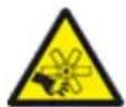
EN Warning of rotating parts!
FR Attention aux parties rotatives!
EN Protect from moisture!
EN Fire, naked flame and smoking forbidden!
FR Hautement inflammable!
CZ Vysoce hořlavé!
text_image
Labeled diagram of a water spray device with numbered components from 1 to 6
text_image
Labeled diagram of a mechanical device with numbered parts including a black component, frame, and various assembly parts.natural_image
Three-panel image showing a hand operating a mechanical lever system, with no visible text or symbols.natural_image
Close-up of hands using a tool to adjust or install a component (no visible text or symbols)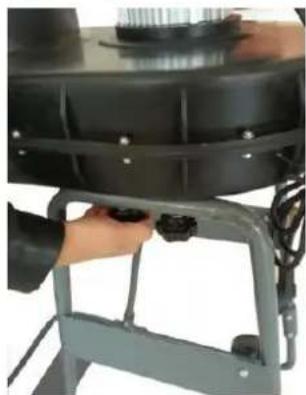
natural_image
Close-up of a hand adjusting a black cylindrical component mounted on a metal frame (no visible text or symbols)
natural_image
Close-up of a hand using a tool to press or install a small metallic component on a dark metal surface (no visible text or symbols)
natural_image
Close-up of a mechanical component with metallic brackets and mounting base, shown from two angles (no visible text or symbols)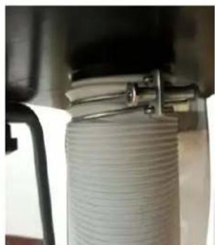
natural_image
Close-up of a coiled white cylindrical component mounted under a mechanical bracket (no visible text or symbols)7 BETRIEB
natural_image
Close-up of a yellow industrial control panel with red and green buttons, no visible text or symbolsNOT-AUS-Schalter:
natural_image
Close-up of a yellow and red plastic component mounted on a black base (no text or symbols visible)8 WARTUNG

ACHTUNG
This manual contains information and important instructions for the installation and correct use of the dust collector ABS 850.
Following the usual commercial name of the device (see cover) is substituted in this manual with the name "machine".
This manual is part of the product and shall not be stored separately from the product. Save it for later reference and if you let other people use the product, add this instruction manual to the product.

Please read and obey the security instructions!
Before first use read this manual carefully. It eases the correct use of the product and prevents misunderstanding and damages of product and the user's health.
Due to constant advancements in product design, construction pictures and content may diverse slightly. However, if you discover any errors, inform us please.
Technical specifications are subject to changes!
Please check the product contents immediately after receipt for any eventual transport damage or missing parts.
Claims from transport damage or missing parts must be placed immediately after initial product receipt and unpacking before putting the product into operation.
Please understand that later claims cannot be accepted anymore.
Copyright
© 2016
This document is protected by international copyright law. Any unauthorized duplication, translation or use of pictures, illustrations or text of this manual will be pursued by law. Court of jurisdiction is the Landesgericht Linz or the competent court for 4170 Haslach, Austria!
Customer service contact
| ABS 850 | |
| 1 | Switch-unit |
| 2 | Chip bag |
| 3 | Dust hose |
| 4 | Fan wheel housing |
| 5 | Motor |
| 6 | Dust bag |
12.2 Delivery content
| ABS 850 | |
| 1 | Bag clamps |
| 2 | Chip bag |
| 3 | Dust bag |
| 4 | Fan wheel housing with motor |
| 5 | Dust hose |
| 6 | Clamp parts |
| 7 | Lower bracket |
| 8 | Bottom panel and side panel |
| 9 | Side bracket |
| 10 | Hardware |
text_image
Labeled diagram of a mechanical device with numbered components from 1 to 6
text_image
Labeled diagram of a mechanical device with numbered parts including a central circular component, frame, and various components.12.3 Technical details
| Motor power S1 (100%) / S6 (40%) | 0,75kW / 1,05kW |
| Chip bag | ∅ 280mm / 900mm |
| Dust bag | ∅ 360mm / 670mm |
| Chip bag volume | 40l |
| Dust collector plug | ∅ 100mm |
| Dust hose length | 2m |
| Collector power | 850m3/h |
| Hypotension | 800Pa |
| Fan wheel diameter | ∅ 230mm |
| Machine dimension (LxWxH) | 740x420x1540mm |
| Weight | 23kg |
| Sound power level LPA | 78dB(A) k: 3dB(A) |
| Sound pressure level LWA | 76,6dB(A) k: 3dB(A) |
13 SAFETY
13.1 Intended Use
The machine must only be used for its intended purpose! Any other use is deemed to be a case of misuse.
To use the machine properly you must also observe and follow all safety regulations, the assembly instructions, operating and maintenance instructions lay down in this manual.
All people who use and service the machine have to be acquainted with this manual and must be informed about the machine's potential hazards.
It is also imperative to observe the accident prevention regulations in force in your area.
The same applies for the general rules of occupational health and safety.
The machine is used for:
Extract of wood dust, wood and plastic chips.
Any manipulation of the machine or its parts is a misuse, in this case HOLZMANN-MASCHINEN and its sales partners cannot be made liable for ANY direct or indirect damage.
Even when the machine is used as prescribed it is still impossible to eliminate certain residual risk factors.

WARNING
- Inflammable gases (e.g. paint or varnish mist) must not be extracted.
- Polyethylene dust bags must be a minimum thickness of 0,2mm!
- When using bags made of other materials the mechanical strength must be the same!
- Refer the user manual of the connected woodworking machine!
Ambient conditions
The machine may be operated:
humidity
max. 70%
temperature
+5°C to +40°C (+41°F to +104°F)
The machine shall not be operated outdoors or in wet or damp areas.
The machine shall not be operated in areas exposed to increased fire or explosion hazard.
Prohibited use
- The operation of the machine outside the stated technical limits described in this manual is forbidden.
• The use of the machine not according with the required dimensions is forbidden. - The use of the machine not being suitable for the use of the machine and not being certified is forbidden.
- Any manipulation of the machine and parts is forbidden.
- The use of the machine for any purposes other than described in this user-manual is forbidden.
• The unattended operation on the machine during the working process is forbidden! - It is not allowed to leave the immediate work area during the work is being performed.
13.2 Security instructions
Missing or non-readable security stickers have to be replaced immediately!
The locally applicable laws and regulations may specify the minimum age of the operator and limit the use of this machine!
To avoid malfunction, machine defects and injuries, read the following security instructions!

- Keep your work area dry and tidy! An untidy work area may cause accidents. Avoid slippery floor.
• Make sure the work area is lighted sufficiently
- Do not overload the machine

- Always stay focused when working. Reduce distortion sources in your working environment. The operation of the machine when being tired, as well as under the influence of alcohol, drugs or concentration influencing medicaments is forbidden.
• Work in a well ventilated area!
• Respectively trained people only and only one person shall operate the machine.
- Do not allow other people, particularly children, to touch the machine or the cable.
- Keep them away from your work area.
• Make your workshop childproof.
- Make sure there is nobody present in the dangerous area. The minimum safety distance is 2m

- Use personal safety equipment: dust mask when working with the machine.
- Never leave the machine running unattended! Before leaving the working area switch the machine off and wait until the machine stops.
• Always disconnect the machine prior to any actions performed at the machine.
- Avoid unintentional starting
- Do not use the machine with damaged switch
- The plug of an electrical tool must strictly correspond to the socket. Do not use any adapters together with earthed electric tools
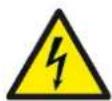
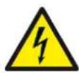
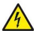
- Each time you work with an electrically operated machine, caution is advised! There is a risk of electric shock, fire, cutting injury;
- Protect the machine from dampness (causing a short circuit)
- Use power tools and machines never in the vicinity of flammable liquids and gases (danger of explosion)
- Check the cable regularly for damage
- When working with the machine outdoors, use extension cables suitable for outdoor use

- Do not use the cable to carry the machine
- Protect the cable from heat, oil and sharp edges
- Avoid body contact with earthed
- FIRE HAZARD:


Especially the aspiration of lightly flammable materials like gases, liquids, metal dust or chippings, solvents, hot ashes, cigarette waste ... is strictly forbidden!
- Do not insert any objections into the dust collector hood and keep hand away from the dust collector hood when machine is connected to power supply.
- Regularly check the dust collector hood for debris and clean it if necessary.
- Do not dismount the protective fence in the dust collector hood. It is a security component and must be left in place.
13.3 Remaining risk factors
Despite of correct and proper use and maintenance there remain some residual risk factors:
Hazard of injury or machine damage due to undetected machine defect
To minimize this risk, check the machine prior to every operation for loose screws and connections. Check the motor noise, the collector tubes, filter bag, dust collector bag and impeller for eventual damage. Damaged parts have to be replaced immediately, no operation of the machine in the meantime!
Hazard of electric shock
Undetected malfunctions in the power supply and/or the connected wood working machine might result in electric shock when touching the machine. Ensure proper electric installation, and let it check periodically by a trained electrician.
Danger due to unintended machine start-up
Eliminate this risk by disconnecting the machine before you perform any checks or activities on the machine.
Hazard of inhaling toxic wood dust
Especially wood dust arising from chemically treated wood and/or lacquer/paint are harmful when inhaled. Therefore let the dust settle for 10 Minutes before you change the dust collector bag and wear a suitable breathing mask if required.
14 ASSEMBLY
14.1 Delivery content
Please check the product contents immediately after receipt for any eventual transport damage or missing parts. Claims from transport damage or missing parts must be placed immediately after initial machine receipt and unpacking before putting the machine into operation. Please understand that later claims cannot be accepted anymore.
14.2 Workplace requirements
The workplace has to fulfill the requirements.
The ground has to be even, in level and hard. It must be suitable at least to weight it with double weight per square meter than the machines net weight.
The chosen workplace must have access to a suitable electric supply net hat complies with the machines requirements.
14.3 Power supply
ATTENTION
When working with non-grounded machines:
Severe injury or even death may arise though electrocution!
Therefore: The machine must be operated at a grounded power socket
The connection of the machine to the electric power supply and the following checks have to be carried out by a respectively trained electrician only.
-
The electronic connection of the machine is designated for operation with a grounded power socket!
-
The connector plug may not be manipulated.
-
The mains supply must be secured with 10A:
-
If the connector plug doesn't fit or if it is defect, only qualified electricians may modify or re-new it!
-
The grounding wire should be held in green-yellow.
-
A damaged cable has to be exchanged immediately!
-
Make sure that a possible extension cord is in good condition and suitable for the transmission of power. An undersized cord reduces the transmission of power and heats up.
-
A damaged cable must be replaced immediately

NOTICE
Operation is only allowed with safety switch against stray current (RCD max. stray current of 30mA)

NOTICE
Use only permitted extension cable with cross-section the one in the following table declared.
| Voltage | Extension | Cross-section |
| 220 V-240 V50 Hz | <27 m | 1,5 mm^2 |
| <44 m | 2,5 mm^2 | |
| <70 m | 4,0 mm^2 | |
| <105 m | 6,0 mm^2 |
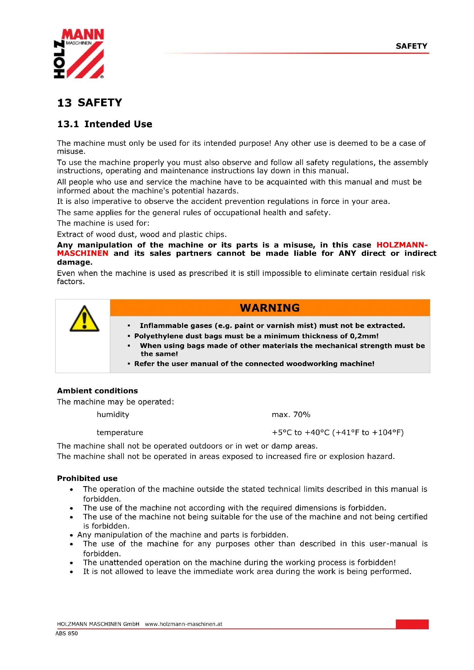
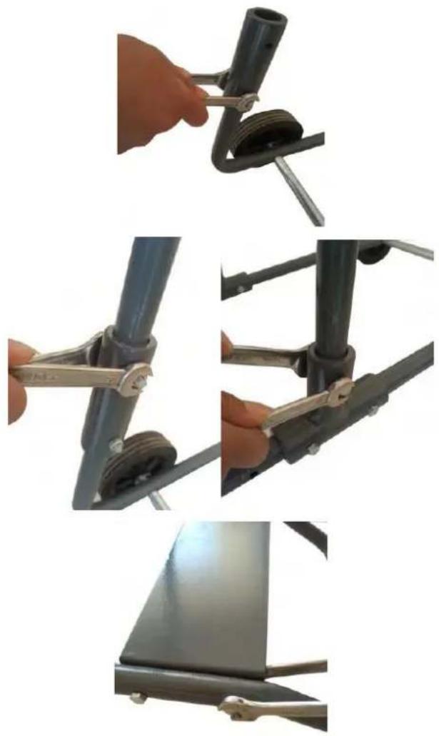
14.4 Assembly
- Place the lower bracket on the floor and loose the bolts M6x35mm on the connector.
- Set side bracket into the connector, use the bolt M6x35mm thread the hole and tighten them.
- Install the bottom panel on the lower bracket
natural_image
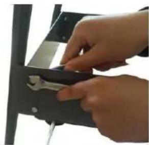
Three-panel image showing a hand operating a mechanical lift tool, with no visible text or symbols.- Install the side panel on the side brackets.
- Using 4 knobs to install the fan wheel housing on the side brackets.
- Install the bag support on the fan wheel housing.
- Set the bag on the fan wheel housing and tighten the bag clamp, then hang the filter bag on the bag support
- Set the hose on the fan wheel housing and tighten the hose clamp
natural_image
Close-up of hands using a tool to adjust or install a component (no visible text or symbols)
natural_image
Close-up of a hand adjusting a black cylindrical component mounted on a metal frame (no visible text or symbols)
natural_image
Close-up of a hand using a tool to press or install a small metallic component on a dark metal surface (no visible text or symbols)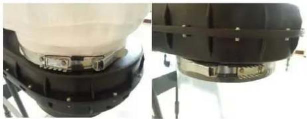
natural_image
Two views of a mechanical device with black and white components, mounted on stands (no visible text or symbols)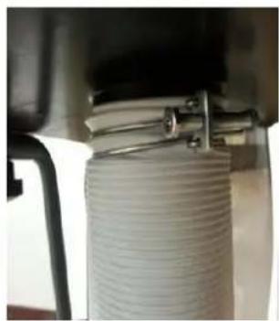
natural_image
Close-up of a coiled white cable or hose component mounted on a mechanical fixture (no visible text or symbols)15 OPERATION
Device to be operated in a perfect state only. Inspect the device visually every time it is to be used. Check in particular the safety equipment, electrical controls, electric cables and screwed connection for damage and if tightened properly. Replace any damaged parts before operating the device.
15.1 Operation instructions
 | WARNING |  |
| Perform all machine settings with the machine being disconnected from the power supply! |

HINWEIS
- Place the machine next to the woodworking machine in a way that it will not interfere with your work!
- Start to work with the woodworking machine only until the dust collector has reached full speed!
15.2 Connection of dust collector to machine
Dust collector plug ABS 850: ∅ 100mm
Ensure dust collector tubes to be composed of hardly inflammable material and antistatic.
The total distance between dust collector hood of the ABS 3000/4000/5000 and machine dust collector hood shall not exceed 10 meters.
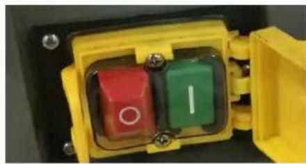
15.3 Switch unit
On-off-switch:
Press green button (I): turn on
Press red button (0): turn off
EMERGENCY-switch:
The flap of the switch unit must always be opened during operation!
For emergencies push on the red cap. The machine switched off immediately!
natural_image
Close-up of a yellow electrical switch with red and green buttons, no visible text or symbols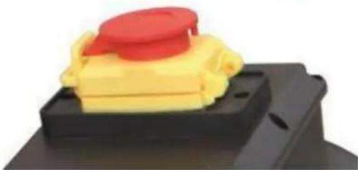
natural_image
Close-up of a yellow plastic component with a red cap on top, placed on a black base (no text or symbols visible)16 MAINTENANCE

ATTENTION
Don't clean or do maintenance on the machine while it is still connected to the power supply:
Damages to machine and injuries might occur due to unintended switching on of the machine!
Therefore: Switch the machine off and disconnect it from the power supply be-fore any maintenance works or cleaning is carried out
The machine does not require extensive maintenance. If malfunctions and defects occur, let it be serviced by trained persons only.
Before first operation as well as later on every 100 operation hours you should lubricate all connecting parts (if required, remove beforehand with a brush all swarfs and dust).
Check regularly the condition of the security stickers. Replace them if required.
Check regularly the condition of the machine.
The good condition and perfect adjustment of the guiding rollers is essential for a smooth band guidance and a clean cut.
Store the machine in a closed, dry location.
NOTICE
Clean your machine regularly after every usage – it prolongs the machines lifespan and is a prerequisite for a safe working environment.
Repair jobs shall be performed by respectively trained professionals only!
16.1 Maintenance plan
- Clean regularly the filter bag to ensure its filter capacity.
- You should check the dust collector hood regularly for deposits that cumulate especially on the protective fence and clean if necessary. Failure to do so will result in lower suction capacity and motor overload.
- Do not dismount the protective fence, it is a security component.
16.1.1 Change of dust collector bag
Empty dust collector bags when they are 60-70% full.
Switch the dust collector off and let the dust settle at least for 10 minutes.
Disconnect the dust collector from the power supply.
Do not use a dust collector bag twice.
Use solely certified dust collector bags, which match with the technical specifications, especially ∅ and height, of the dust collector
16.2 Cleaning
After each workshift the machine has to be cleaned. Remove chips etc. with a suitable tool. Do not remove them by hand (cutting injury!). Remove dust as well.

NOTICE
The usage of certain solutions containing ingredients damaging metal surfaces as well as the use of scrubbing agents will damage the machine surface! Clean the machine surface with a wet cloth soaked in a mild solution
16.3 Disposal
Do not dispose the machine in residual waste. Contact your local authorities for information regarding the available disposal options. When you buy at your local dealer for a replacement unit, the latter is obliged to exchange your old.

17 TROUBLE SHOOTING
BEFORE YOU START WORKING FOR THE ELIMINATION OF DEFECTS, DISCONNECT THE MACHINE FROM THE POWER SUPPLY.
| Trouble | Possible cause | Solution |
| The magnetic support has no magnetic force | Switch defective | Repair switch |
| Power supply is off | Repair power supply | |
| Fuse is defectivet | Change fuse | |
| Electric contactor is defective | Repair or change electric contactor | |
| Dust emerges from | Leaking or blocked connections | Check connectionRemove blockages |
| Dust bag or filter bag is defective or incorrectly installed | Check bagsChange defective bags | |
| Loud noise in the fan wheel housing | Extracting of a big part | Switch of the machine, disconnect the machine and remove the part |
| Loosen fan wheel | Tighten the fan wheel |
MANY POTENTIAL SOURCES OF ERROR CAN BE CLEARED BY THE EXPERTLY CONNECTION TO THE ELECTRICITY GRID.

NOTICE
Should you in necessary repairs not able to properly to perform or you have not the prescribed training for it always attract a workshop to fix the problem.
18 PRÉFACE (FR)
Cher Client,
text_image
Labeled diagram of a mechanical device with numbered components from 1 to 6
text_image
Labeled diagram of a mechanical device with numbered parts including a central circular component, frame, and various components.natural_image
Three-panel image showing a hand operating a mechanical lift tool, with separate views of the same components (no text or symbols visible)natural_image
Close-up of hands using a tool to adjust or install a metal component (no visible text or symbols)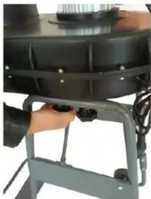
natural_image
Close-up of a person adjusting a black cylindrical device mounted on a metal frame (no visible text or symbols)
natural_image
Close-up of a hand using a tool to press a small metallic component on a dark surface (no text or symbols visible)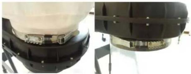
natural_image
Close-up of two mechanical components with black and white surfaces, mounted on stands (no visible text or symbols)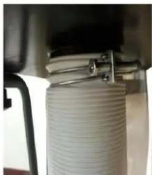
natural_image
Close-up of a coiled white cylindrical object with metal clamps, mounted under a mechanical frame (no visible text or symbols)22 UTILISATION
natural_image
Close-up of a yellow industrial electrical switch with red and green buttons (no text or symbols visible)BOUTON D'ARRET D'URGENCE:
natural_image
Close-up of a yellow plastic component with a red cap on top, mounted on a black base (no text or symbols visible)23 ENTRETIEN

ATTENTI ON
text_image
Labeled diagram of a spray gun with numbered components from 1 to 6
text_image
Labeled diagram of a mechanical device with numbered parts including a central component, frame, and various assembly parts.27 BEZPEČNOST
27.1 Učel použiti
natural_image
Three-panel image showing a hand operating a metal frame with a tool, alongside a close-up of the same mechanical component (no text or symbols visible)natural_image
Three-panel image showing a hand operating a mechanical device with a tool, no visible text or symbols.
natural_image
Close-up of a mechanical component with black and white parts, mounted on a stand (no visible text or symbols)
natural_image
Close-up of a coiled white cylindrical component mounted under a mechanical bracket (no visible text or symbols)29 PROVOZ
natural_image
Close-up of a yellow electrical switch with red and green buttons, no visible text or symbolsNOUZOVÝ vypínač:
natural_image
Close-up of a yellow plastic component with a red lid, mounted on a black base (no text or symbols visible)30 ÚDRŽBA

POZOR
text_image
Labeled diagram of a spray gun with numbered components from 1 to 6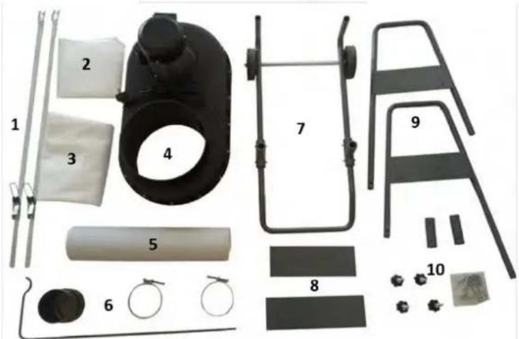
text_image
Labeled diagram of a mechanical device with numbered parts including a black component, frame, and various assembly pieces.34 SICUREZZA
34.1 Uso conforme previsto
natural_image
Three-panel image showing a hand operating a mechanical lever with a tool, alongside a close-up of the lever assembly (no text or symbols visible)natural_image
Three-panel image showing a hand operating a mechanical device with a tool, no visible text or symbols.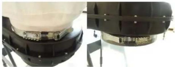
natural_image
Close-up of two mechanical components with metallic brackets and mounting hardware (no visible text or symbols)
natural_image
Close-up of a coiled white cylindrical component mounted under a mechanical bracket (no visible text or symbols)36 USO
natural_image
Close-up of a yellow industrial control panel with red and green buttons, no visible text or symbolsnatural_image
Close-up of a yellow plastic component with a red lid, mounted on a black base (no text or symbols visible)37 MANUTENZIONE

ATTENZIONE
text_image
Labeled diagram of a mechanical device with numbered components from 1 to 6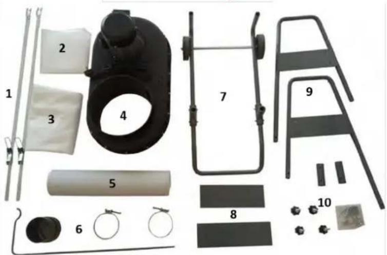
text_image
Labeled diagram of a mechanical device with numbered components for assembly or maintenance reference.41 VEILIGHEID
41.1 Reglementaire toepassing
natural_image
Three-panel image showing a hand operating a mechanical lever with a tool, alongside a close-up of the lever mechanism (no text or symbols visible)natural_image
Close-up of hands using a pliers to adjust or install a small component (no visible text or symbols)
natural_image
Close-up of a hand adjusting a black cylindrical component mounted on a metal frame (no visible text or symbols)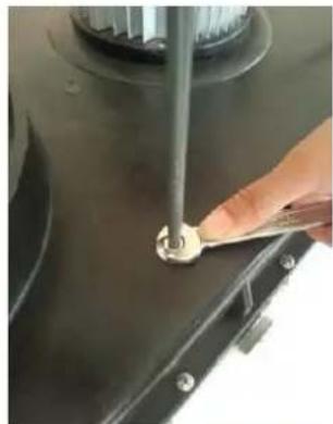
natural_image
Close-up of a hand using a tool to press or install a small metallic component on a dark metal surface (no visible text or symbols)
natural_image
Close-up of a black mechanical component with metallic fittings, mounted on a stand (no visible text or symbols)
natural_image
Close-up of a coiled white cylindrical component mounted under a mechanical bracket (no visible text or symbols)43 BEDRIJF
natural_image
Close-up of a yellow industrial control panel with red and green buttons, no visible text or symbolsNOODSTOP-schakelaar:
natural_image
Close-up of a yellow plastic component with a red cap on top, placed on a black base (no text or symbols visible)44 ONDERHOUD

OPGELET
text_image
PE M MAIN SWITCH 1 O C PE47 ERSATZTEILE / SPARE PARTS
With original HOLZMANN spare parts you use parts that are attuned to each other shorten the installation time and elongate your products lifespan.
IMP OR TAN T
The installation of other than original spare parts voids the warranty!
So you always have to use original spare parts
When you place a spare parts order please use the service formular you can find in the last chapter of this manual. Always take a note of the machine type, spare parts number and partname. We recommend to copy the spare parts diagram and mark the spare part you need.
You find the order address in the preface of this operation manual.
text_image
Exploded view diagram of a portable air conditioner with numbered parts for identification| NO. | DESCRIPTION | NO. | DESCRIPTION |
| 1 | Power cord | 27 | Rear plate |
| 2 | Pan head screw M4x55mm | 28 | Bracket A |
| 3 | Switch box | 29 | Bracket B |
| 4 | Motor | 30 | Bracket C |
| 5 | Tapping screw ST4.2x10mm | 31 | Bracket C-1 |
| 6 | Switch | 32 | Nut M6 |
| 7 | Flat washer 8mm | 33 | Hex. head bolts M6x35mm |
| 8 | Spring washer 8mm | 34 | Mitre joint A |
| 9 | Hex. head bolts M8x20mm | 35 | Hex. head bolts M6x35mm |
| 10 | Turbo fan | 36 | Mitre joint B |
| 11 | Spacer, turbo fan | 37 | Nut M6 |
| 12 | Allen screw M6x20mm (LH) | 38 | Sub-plate |
| 13 | Hose clamp | 39 | Collector bag |
| 14 | Hose | 40 | Bag clamp |
| 15 | Hose clamp | 41 | Collector bottom |
| 16 | Outlet | 42 | Knob M8x40mm |
| 17 | Flat washer 12mm | 43 | Flat washer 8mm |
| 18 | Wheel | 44 | Collector cover |
| 19 | Flat washer 12mm | 45 | Nut M4 |
| 20 | Cotter pin 3.2x14 | 46 | Spring washer 4mm |
| 21 | Wheel shaft | 47 | Flat washer 4mm |
| 22 | Hex. head bolts M6x35mm | 48 | Pan head screw M4x20mm |
| 23 | Connect plate | 49 | Filter bag |
| 24 | Nut M6 | 50 | Filter bag support |
| 25 | Nut M6 | 51 | Bag clamp |
| 26 | Hex. head bolts M6x12mm |
48 EU-KONFORMITÄTSERKLÄRUNG/CE-CERTIFICATE OF CONFORMITY

Inverkehrbringer / Distributor
Hereby we declare that the above mentioned machines meet the essential safety and health requirements of the above stated EC directives. Any manipulation or change of the machine not being explicitly authorized by us in advance renders this document null and void.
Please consult our troubleshooting section for initial problem solving. Feel free to contact your HOLZMANN reseller or us for Customer Support!
Warranty claims based on your sales contract with your HOLZMANN retailer, including your statutory rights, shall not be affected by this guarantee declaration. HOLZMANN-MASCHINEN grants guarantee according to following conditions:
A) The guarantee covers the correction of deficiencies to the tool/product, at no charge, if it can be verified adequately that the deficiencies were caused by a material or manufacturing fault.
B) The guarantee period lasts 12 months, and is reduced to 6 months for tools in commercial use. The guarantee period begins from the time the new tool is purchased from the first end user. The starting date is the date on the original delivery receipt, or the sales receipt in the case of pickup by the customer.
C) Please lodge your guarantee claims to your HOLZMANN reseller you acquired the claimed tool from with following information:
Original Sales receipt and/or delivery receipt
Service form (see next page) filed, with a sufficient deficiency report
for spare part claims: a copy of the respective exploded drawing with the required spare parts being marked clear and unmistakable.
D) The Guarantee handling procedure and place of fulfillment is determined according to HOLZMANNs sole discretion in accordance with the HOLZMANN retail partner. If there is no additional Service contract made including on-site service, the place of fulfillment is principally the HOLZMANN Service Center in Haslach, Austria.
Transport charges for sending to and from our Service Center are not covered in this guarantee.
E) The Guarantee does not cover:
- Wear and tear parts like belts, provided tools etc., except to initial damage which has to be claimed immediately after receipt and initial check of the product.
- Defects in the tool caused by non-compliance with the operating instructions, improper assembly, insufficient power supply, improper use, abnormal environmental conditions, inappropriate operating conditions, overload or insufficient servicing or maintenance.
- Damages being the causal effect of performed manipulations, changes, additions made to the product.
- Defects caused by using accessories, components or spare parts other than original HOLZMANN spare parts.
- Slight deviations from the specified quality or slight appearance changes that do not affect functionality or value of the tool.
- Defects resulting from a commercial use of tools that - based on their construction and power output - are not designed and built to be used within the frame of industrial/commercial continuous load.
F) Claims other than the right to correction of faults in the tool named in these guarantee conditions are not covered by our guarantee.
G) This guarantee is voluntary. Therefore Services provided under guarantee do not lengthen or renew the guarantee period for the tool or the replaced part.
SERVICE
After Guarantee and warranty expiration specialist repair shops can perform maintenance and repair jobs. But we are still at your service as well with spare parts and/or product service. Place your spare part / repair service cost inquiry by filing the SERVICE form on the following page and send it:
via Mail to info@holzmann-maschinen.at
or via Fax to: +43 7289 71562 4
51 GARANTIE ET SERVICE
We observe the quality of our delivered products in the frame of a Quality Management policy.
Your opinion is essential for further product development and product choice. Please let us know about your:
- Impressions and suggestions for improvement.
- experiences that may be useful for other users and for product design
- Experiences with malfunctions that occur in specific operation modes
We would like to ask you to note down your experiences and observations and send them to us via FAX, E-Mail or by post:
Please describe amongst others in the problem: What has cause the problem/defect, what was the last activity before you noticed the problem/defect? For electrical problems: Have you had checked you electric supply and the machine already by a certified electrician;
3. Bitte beachten
Additional information
INCOMPLETELY FILLED SERVICE FORMS CANNOT BE PROCESSED! FOR GUARANTEE CLAIMS PLEASE ADD A COPY OF YOUR ORIGINAL SALES / DELIVERY RECEIPT OTHERWISE IT CANNOT BE ACCEPTED. FOR SPARE PART ORDERS PLEASE ADD TO THIS SERVICE FORM A COPY OF THE RESPECTIVE EXPLODED DRAWING WITH THE REQUIRED SPARE PARTS BEING MARKED CLEARLY AND UNMISTAKABLE. THIS HELPS US TO IDENTIFY THE REQUIRED SPARE PARTS FASTLY AND ACCEL- ERATES THE HANDLING OF YOUR INQUIRY.