YSTSW215 - Speakers YAMAHA - Free user manual and instructions
Find the device manual for free YSTSW215 YAMAHA in PDF.
| Product Type | Active subwoofer |
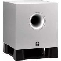
| Brand and Model | YAMAHA YST-SW215 |
| Technology | Advanced YST (Active Servo Technology), QD-Bass (Quad Dispersion Bass) |
| Speaker | 20 cm cone woofer (JA2165) with magnetic shielding |
| Amplifier Power | 120 W (100 Hz, 5 ohms, 10% THD) |
| Frequency Response | 28 Hz – 160 Hz (-10 dB) |
| Power Supply | 100-240 V AC, 50/60 Hz (depending on model) |
| Power Consumption | 95 W (operation), 0.5 W (standby) |
| Controls and Adjustments | Volume, HIGH CUT (40-140 Hz), B.A.S.S. (Music/Movie), Phase (NORM/REV), auto standby (AUTO STANDBY HIGH/LOW/OFF) |
| Connections | Line inputs (INPUT2) and speaker inputs/outputs (INPUT1/OUTPUT) |
| Special Features | Auto standby, voltage selector (on some models) |
| Cleaning | Use a clean, dry cloth. Do not use chemical solvents. |
| Safety | Do not open the enclosure, do not expose to rain or moisture, leave at least 20 cm of space around for ventilation. |
| Supplied Accessories | Non-slip pads |
| Repairability | No user-serviceable parts. Contact a YAMAHA authorized service center. |
Frequently Asked Questions - YSTSW215 YAMAHA
User questions about YSTSW215 YAMAHA
0 question about this device. Answer the ones you know or ask your own.
Ask a new question about this device
Download the instructions for your Speakers in PDF format for free! Find your manual YSTSW215 - YAMAHA and take your electronic device back in hand. On this page are published all the documents necessary for the use of your device. YSTSW215 by YAMAHA.
USER MANUAL YSTSW215 YAMAHA
- Explanation of Graphical Symbols
The lightning flash with arrowhead symbol, within an equilateral triangle, is intended to alert you to the presence of uninsulated "dangerous voltage" within the product's enclosure that may be of sufficient magnitude to constitute a risk of electric shock to persons.

The exclamation point within an equilateral triangle is intended to alert you to the presence of important operating and maintenance (servicing) instructions in the literature accompanying the appliance.
WARNING
TO REDUCE THE RISK OF FIRE OR ELECTRIC SHOCK, DO NOT EXPOSE THIS APPLIANCE TO RAIN OR MOISTURE.
IMPORTANT
Please record the serial number of this system in the space below.
Model:
Serial No.:
The serial number is located on the rear of the main unit.
Retain this Owner's Manual in a safe place for future reference.
1 Read these instructions.
2 Keep these instructions.
3 Heed all warnings.
4 Follow all instructions.
5 Do not use this apparatus near water.
6 Clean only with dry cloth.
7 Do not block any ventilation openings. Install in accordance with the manufacturer's instructions.
8 Do not install near any heat sources such as radiators, heat registers, stoves, or other apparatus (including amplifiers) that produce heat.
9 Do not defeat the safety purpose of the polarized or grounding-type plug. A polarized plug has two blades with one wider than the other. A grounding type plug has two blades and a third grounding prong. The wide blade or the third prong are provided for your safety. If the provided plug does not fit into your outlet, consult an electrician for replacement of the obsolete outlet.
10 Protect the power cord from being walked on or pinched particularly at plugs, convenience receptacles, and the point where they exit from the apparatus.
11 Only use attachments/accessories specified by the manufacturer.
12 Use only with the cart, stand, tripod, bracket, or table specified by the manufacturer, or sold with the apparatus. When a cart is used, use caution when moving the cart/ apparatus combination to avoid injury from tip-over.

13 Unplug this apparatus during lightning storms or when unused for long periods of time.
14 Refer all servicing to qualified service personnel. Servicing is required when the apparatus has been damaged in any way, such as power-supply cord or plug is damaged, liquid has been spilled or objects have fallen into the apparatus, the apparatus has been exposed to rain or moisture, does not operate normally, or has been dropped.
- Be sure to allow spaces of at least 20 cm above, behind and on both sides of the unit.
- Do not place the following objects on the unit: A vessel with water in it. If the vessel falls by vibrations and water spills, it may cause damage to the unit, and/or you may get an electric shock.
FCC INFORMATION (for US customers)
1 IMPORTANT NOTICE : DO NOT MODIFY THIS UNIT!
This product, when installed as indicated in the instructions contained in this manual, meets FCC requirements. Modifications not expressly approved by Yamaha may void your authority, granted by the FCC, to use the product.
2 IMPORTANT : When connecting this product to accessories and/or another product use only high quality shielded cables. Cable/s supplied with this product MUST be used. Follow all installation instructions. Failure to follow instructions could void your FCC authorization to use this product in the USA.
3 NOTE : This product has been tested and found to comply with the requirements listed in FCC Regulations, Part 15 for Class “B” digital devices. Compliance with these requirements provides a reasonable level of assurance that your use of this product in a residential environment will not result in harmful interference with other electronic devices.
This equipment generates/uses radio frequencies and, if not installed and used according to the instructions found in the users manual, may cause interference harmful to the operation of other electronic devices.
Compliance with FCC regulations does not guarantee that interference will not occur in all installations. If this product is found to be the source of interference, which can be determined by turning the unit “OFF” and “ON”, please try to eliminate the problem by using one of the following measures:
Relocate either this product or the device that is being affected by the interference.
Utilize power outlets that are on different branch (circuit breaker or fuse) circuits or install AC line filter/s.
In the case of radio or TV interference, relocate/reorient the antenna. If the antenna lead-in is 300 ohm ribbon lead, change the lead-in to coaxial type cable.
If these corrective measures do not produce satisfactory results, please contact the local retailer authorized to distribute this type of product. If you can not locate the appropriate retailer, please contact Yamaha Electronics Corp., U.S.A. 6660 Orangethorpe Ave, Buena Park, CA 90620.
The above statements apply ONLY to those products distributed by Yamaha Corporation of America or its subsidiaries.
We Want You Listening For A Lifetime
YAMAHA and the Electronic Industries Association's Consumer Electronics Group want you to get the most out of your equipment by playing it at a safe level. One that lets the sound come through loud and clear without annoying blaring or distortion – and, most importantly, without affecting your sensitive hearing.
Since hearing damage from loud sounds is often undetectable until it is too late, YAMAHA and the Electronic Industries Association's Consumer Electronics Group recommend you to avoid prolonged exposure from excessive volume levels.

CAUTION: Read this before operating your unit
Please read the following operating precautions before use. YAMAHA will not be held responsible for any damage and/or injury caused by not following the cautions below.
- To assure the finest performance, please read this manual carefully. Keep it in a safe place for future reference.
- Install this unit in a cool, dry, clean place - away from windows, heat sources, sources of excessive vibration, dust, moisture and cold. Avoid sources of humming (transformers, motors). To prevent fire or electrical shock, do not expose this unit to rain or water.
- Never open the cabinet. If something drops into the set, contact your dealer.
- The voltage to be used must be the same as that specified on the rear panel. Using this unit with a higher voltage than specified is dangerous and may cause a fire and/or electric shock.
- To reduce the risk or fire or electric shock, do not expose this unit to rain or moisture.
- Do not use force on switches, controls or connection wires. When moving the unit, first disconnect the power plug and the wires connected to other equipments. Never pull the wires themselves.
- When not planning to use this unit for a long period (ie., vacation, etc.), disconnect the AC power plug from the wall outlet.
- To prevent lightning damage, disconnect the AC power plug when there is an electric storm.
- Since this unit has a built-in power amplifier, heat will radiate from the rear panel. Place the unit apart from the walls, allowing at least 20cm of space above, behind and on both sides of the unit to prevent fire or damage. Furthermore, do not position with the rear panel facing down on the floor or other surfaces.
- Do not cover the rear panel of this unit with a newspaper, a tablecloth, a curtain, etc. in order not to obstruct heat radiation. If the temperature inside the unit rises, it may cause fire, damage to the unit and/or personal injury.
-
Do not place the following objects on this unit: Glass, china, small metallic etc.
If glass etc. falls by vibrations and breaks, it may cause bodily injury.
A burning candle etc.
If the candle falls by vibrations, it may cause fire and bodily injury.
A vessel with water in it
If the vessel falls by vibrations and water spills, it may cause damage to the speaker, and/or you may get an electric shock. -
Do not place this unit where foreign objects such as water drips might fall. It might cause a fire, damage to this unit, and/or personal injury.
- Never put a hand or a foreign object into the YST port located on the right side of this unit. When moving this unit, do not hold the port as it might cause personal injury and/or damage to this unit.
- Never place a fragile object near the YST port of this unit. If the object falls or drops by the air pressure, it may cause damage to the unit and/or personal injury.
- Never open the cabinet. It might cause an electric shock since this unit uses a high voltage. It might also cause personal injury and/or damage to this unit.
- When using a humidifier, be sure to avoid condensation inside this unit by allowing enough spaces around this unit or avoiding excess humidification. Condensation might cause a fire, damage to this unit, and/or electric shock.
- Super-bass frequencies reproduced by this unit may cause a turntable to generate a howling sound. In such a case, move this unit away from the turntable.
- This unit may be damaged if certain sounds are continuously outputted at high volume level. For example, if 20 Hz-50 Hz sine waves from a test disc, bass sounds from electronic instruments, etc. are continuously outputted, or when the stylus of a turntable touches the surface of a disc, reduce the volume level to prevent this unit from being damaged.
- If you hear distorted noise (i.e., unnatural, intermittent “rapping” or “hammering” sounds) coming from this unit, reduce the volume level. Extremely loud playing of a movie soundtrack’s low frequency, bass-heavy sounds or similarly loud popular music passages can damage this speaker system.
- Vibration generated by super-bass frequencies may distort images on a TV. In such a case, move this unit away from the TV set.
- Do not attempt to clean this unit with chemical solvents as this might damage the finish. Use a clean, dry cloth.
- Be sure to read the “TROUBLESHOOTING” section regarding common operating errors before concluding that the unit is faulty.
- Secure placement or installation is the owner's responsibility. YAMAHA shall not be liable for any accident caused by improper placement or installation of speakers.
• VOLTAGE SELECTOR
(For China, Korea and General models)
The voltage selector switch on the rear panel of this unit must be set for your local main voltage BEFORE plugging this unit into the AC main supply. Voltages are 110/120/220/240 V AC, 50/60 Hz.
Standby mode
When this unit is turned off by pressing the STANDBY/ON button on the front panel, this unit consumes a small amount of power. This state is called the standby mode. This unit's power supply is completely cut off from the AC line only when the POWER switch on the rear panel is set in the OFF position or the AC power cord is disconnected.
This unit features a magnetically shielded design, but there is still a chance that placing it too close to a TV set might impair picture color. Should this happen, move this unit away from the TV set.
For U.K. customers
If the socket outlets in the home are not suitable for the plug supplied with this appliance, it should be cut off and an appropriate 3 pin plug fitted. For details, refer to the instructions described below.
Note: The plug severed from the mains lead must be destroyed, as a plug with bared flexible cord is hazardous if engaged in a live socket outlet.
SPECIAL INSTRUCTIONS FOR U.K. MODEL
IMPORTANT:
THE WIRES IN MAINS LEAD ARE COLOURED IN ACCORDANCE WITH THE FOLLOWING
CODE:
Blue: NEUTRAL
Brown: LIVE
As the colours of the wires in the mains lead of this apparatus may not correspond with the coloured markings identifying the terminals in your plug, proceed as follows: The wire which is coloured BLUE must be connected to the terminal which is marked with the letter N or coloured BLACK. The wire which is coloured BROWN must be connected to the terminal which is marked with the letter L or coloured RED. Making sure that neither core is connected to the earth terminal of the three pin plug.
For Canadian Customers
To prevent electric shock, match wide blade of plug to wide slot and fully insert.
This Class B digital apparatus complies with
Canadian ICES-003.
CONTENTS
CAUTION ....1
FEATURES 3
SUPPLIED ACCESSORIES....3
PLACEMENT 4
CONNECTIONS 5
☐Connecting to line output (pin jack) terminals of the amplifier 5
②Connecting to speaker output terminals of the amplifier 8
Connecting to the INPUT1/ OUTPUT terminals of the subwoofer ....12
Plug in the subwoofer to the AC outlet .....12
CONTROLS AND THEIR FUNCTIONS .... 13
AUTOMATIC POWER-SWITCHING
FUNCTION 15
ADJUSTING THE SUBWOOFER
BEFORE USE 16
Frequency characteristics ....17
ADVANCED YAMAHA ACTIVE SERVO
TECHNOLOGY 18
TROUBLESHOOTING 19
SPECIFICATIONS ....20
FEATURES
- This subwoofer system employs Advanced Yamaha Active Servo Technology which Yamaha has developed for reproducing higher quality super-bass sound. (Refer to page 18 for details on Advanced Yamaha Active Servo Technology.) This super-bass sound adds a more realistic, theater-in-the-home effect to your stereo system.
- This subwoofer can be easily added to your existing audio system by connecting to either the speaker terminals or the line output (pin jack) terminals of the amplifier.
- For the effective use of the subwoofer, the subwoofer's super-bass sound should be matched to the sounds of your main speakers. You can create the best sound quality for various listening conditions by using the HIGH CUT control and the PHASE switch.
- The Automatic power-switching function saves you the trouble of pressing the STANDBY/ON button to turn the power on and off.
- You can select bass effect suitable for the source by using the B.A.S.S. button.
QD-Bass
TECHNOLOGY
QD-Bass Technology
QD-Bass (Quatre Dispersion Bass) technology uses square, pyramid-shaped reflective plates to radiate the sound in four horizontal directions.
SUPPLIED ACCESSORIES
After unpacking, check that the following parts are contained.
Non-skid pads
PLACEMENT
A
flowchart
graph TD
    A["Square"] --> B["Arrow to bottom"]
    C["Square"] --> D["Arrow to top"]
    E["Square"] --> F["Arrow to bottom"]
B
flowchart
graph TD
    A["Square"] --> B{Loop}
    B --> C["Square"]
    B --> D["Square"]
    C --> E["Loop"]
    D --> E
    E --> F["Square"]
C
flowchart
graph TD
    A[" "] --> C[" "]
    B[" "] --> C[" "]
    C --> D[" "]
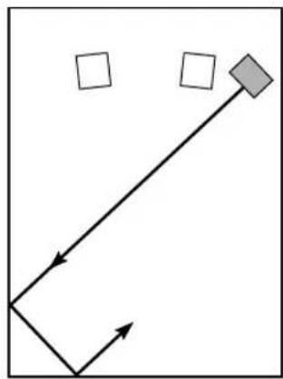
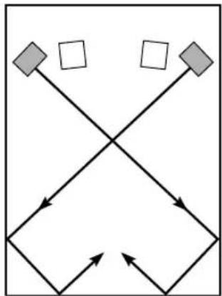
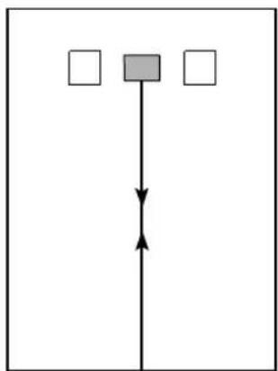
( : subwoofer, : main speaker)
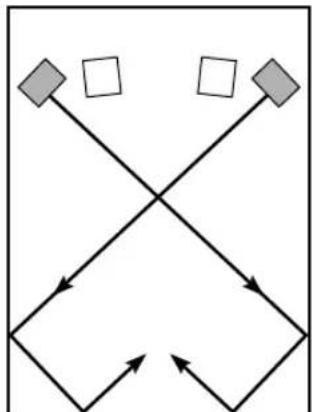
One subwoofer will have a good effect on your audio system, however, the use of two subwoofers is recommended to obtain more effect.
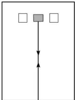
If using one subwoofer, it is recommended to place it on the outside of either the right or the left main speaker. (See fig. A) If using two subwoofers, it is recommended to place them on the outside of each main speaker. (See fig. B) The placement shown in fig. is also possible, however, if the subwoofer system is placed directly facing the wall, the bass effect may die because the sound from it and the sound reflected by the wall may cancel out each other. To prevent this from happening, face the subwoofer system at an angle as in fig. A: .
Note
There may be a case that you cannot obtain enough superbass sounds from the subwoofer when listening in the center of the room. This is because “standing waves” have been developed between two parallel walls and they cancel the bass sounds.
In such a case, face the subwoofer obliquely to the wall. It also may be necessary to break up the parallel surfaces by placing bookshelves etc. along the walls.
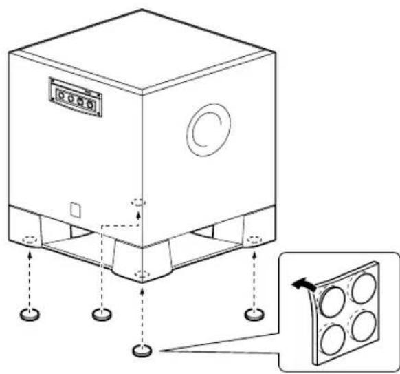
Use the non-skid pads
Put the provided non-skid pads at the four corners on the bottom of the subwoofer to prevent the subwoofer from moving by vibrations etc.
natural_image
Technical line drawing of a rectangular industrial machine with mounting holes and a side panel inset showing four circular components (no text or symbols)CONNECTIONS
Choose one of the following two connecting methods that is more suitable for your audio system.
■Choose 1 pages 5-7) if your amplifier has line output (pin jack) terminal(s)
■Choose ② (pages 8-11) if your amplifier has no line output (pin jack) terminal
Caution: Unplug the subwoofer and other audio/video components before making connections.
Notes
- All connections must be correct, that is to say L (left) to L, R (right) to R, “+” to “+” and “−” to “−”. Also, refer to the owner’s manual of your component to be connected to the subwoofer.
- After all connections are completed, plug in the subwoofer and other audio/video components.
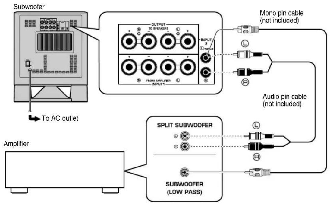
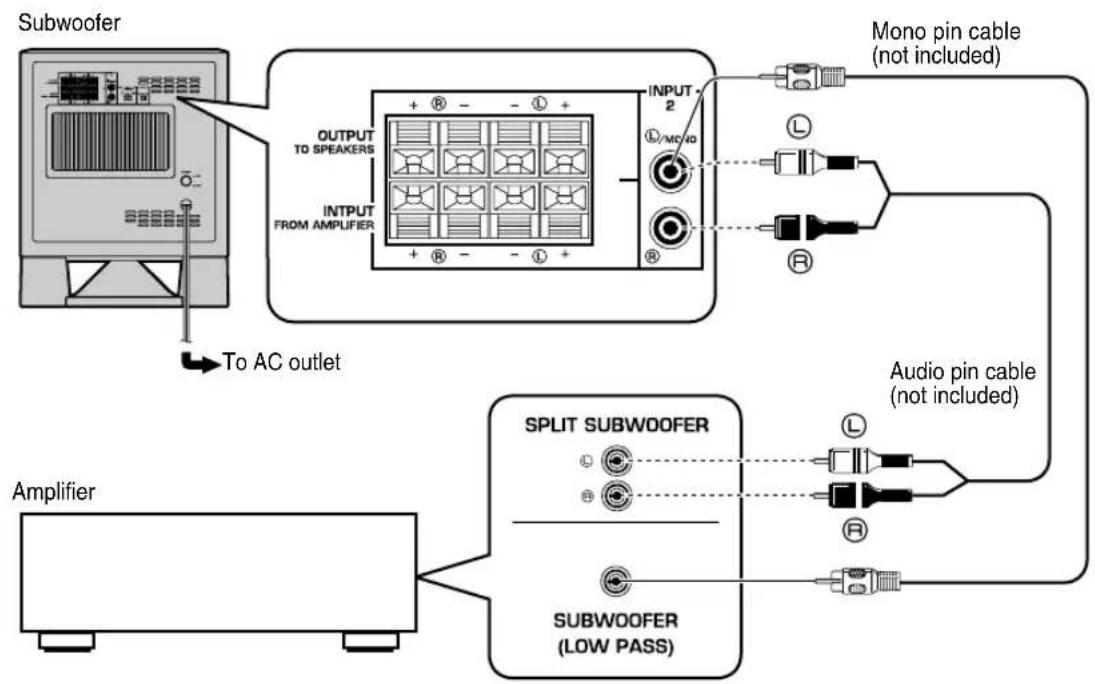
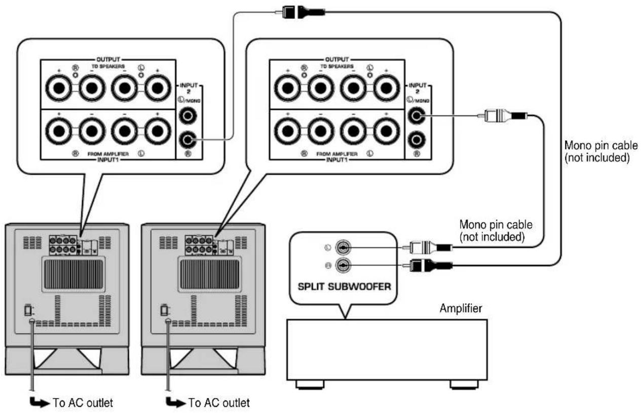
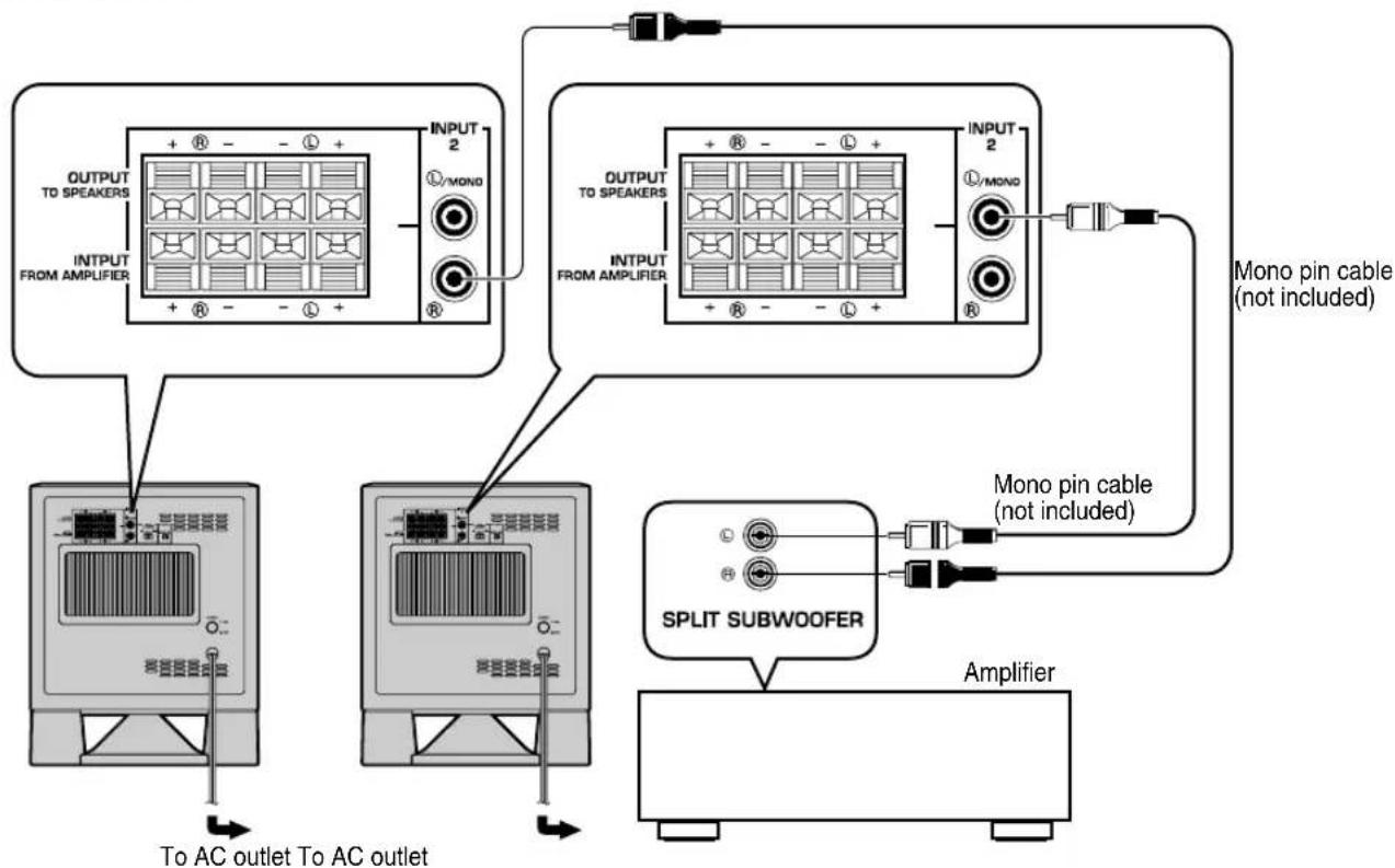
1 Connecting to line output (pin jack) terminals of the amplifier
- To connect with a YAMAHA DSP amplifier (or AV receiver), connect the SUBWOOFER (or LOW PASS etc.) terminal on the rear of the DSP amplifier (or AV receiver) to the Ⓐ/MONO INPUT2 terminal of the subwoofer.
- When connecting the subwoofer to the SPLIT SUBWOOFER terminals on the rear of the DSP amplifier, be sure to connect the Ⓐ/MONO INPUT2 terminal to the “L” side and the Ⓡ INPUT2 terminal to the “R” side of the SPLIT SUBWOOFER terminals.
Notes
- Some amplifiers have line output terminals labeled PRE OUT. When you connect the subwoofer to the PRE OUT terminals of the amplifier, make sure that the amplifier has at least two sets of PRE OUT terminals. If the amplifier has only one set of PRE OUT terminals, do not connect the subwoofer to the PRE OUT terminals. Instead, connect the subwoofer to the speaker output terminals of the amplifier. (Refer to pages 8-11.)
- When connecting to a monaural line output terminal of the amplifier, connect the Ⓛ/MONO INPUT2 terminal.
- When connecting to line output terminals of the amplifier, other speakers should not be connected to the OUTPUT terminals on the rear panel of the subwoofer. If connected, they will not produce sound.
■Using one subwoofer
flowchart
graph TD
    A["Amplifier"] --> B["SPLIT SUBWOOFER"]
    B --> C["Output to Speaker 1"]
    C --> D["Mono pin cable (not included)"]
    C --> E["Audio pin cable (not included)"]
    B --> F["Subwoofer (LOW PASS)"]
    style A fill:#f9f,stroke:#333
    style B fill:#ccf,stroke:#333
    style C fill:#cfc,stroke:#333
    style D fill:#fcc,stroke:#333
    style E fill:#cff,stroke:#333
    style F fill:#ffc,stroke:#333
flowchart
graph TD
    A["Subwoofer"] --> B["OUTPUT TO SPEAKERS"]
    A --> C["INPUT FROM AMPLIFIER"]
    B --> D["INPUT 2 L/MC/ID"]
    C --> D
    D --> E["Mono pin cable (not included)"]
    D --> F["Audio pin cable (not included)"]
    G["Amplifier"] --> H["SPLIT SUBwoofer"]
    H --> I["SUBwoofer (LOW PASS)"]
    I --> J["To AC outlet"]
■ Using two subwoofers
flowchart
graph TD
    A["OUTPUT TO SPEAKERS INPUT 1"] --> B["COMPROM"]
    C["OUTPUT TO SPEAKERS INPUT 2"] --> D["COMPROM"]
    E["OUTPUT TO SPEAKERS INPUT 3"] --> F["COMPROM"]
    G["COMPROM"] --> H["AMPIFIER"]
    I["COMPROM"] --> J["SPLIT SUBWOOFER"]
    K["COMPROM"] --> L["AMPIFIER"]
    M["Multi-pin cable (not included)"] --> N["Output to Speaker"]
    O["Multi-pin cable (not included)"] --> P["Output to Subwoofer"]
flowchart
graph TD
    A["OUTPUT TO SPEAKERS"] --> B["INPUT FROM AMPLIFIER"]
    C["OUTPUT TO SPEAKERS"] --> D["INPUT FROM AMPLIFIER"]
    E["SPLIT SUBWOOFER"] --> F["Amplifier"]
    B --> G["To AC outlet To AC outlet"]
    D --> H["To AC outlet To AC outlet"]
    I["Mono pin cable (not included)"] --> J["INPUT 2"]
    K["Mono pin cable (not included)"] --> L["INPUT 2"]
    style A fill:#f9f,stroke:#333
    style C fill:#f9f,stroke:#333
    style E fill:#f9f,stroke:#333
    style K fill:#f9f,stroke:#333
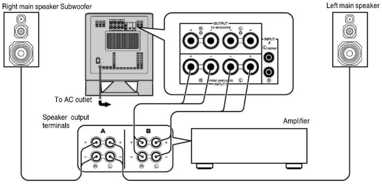
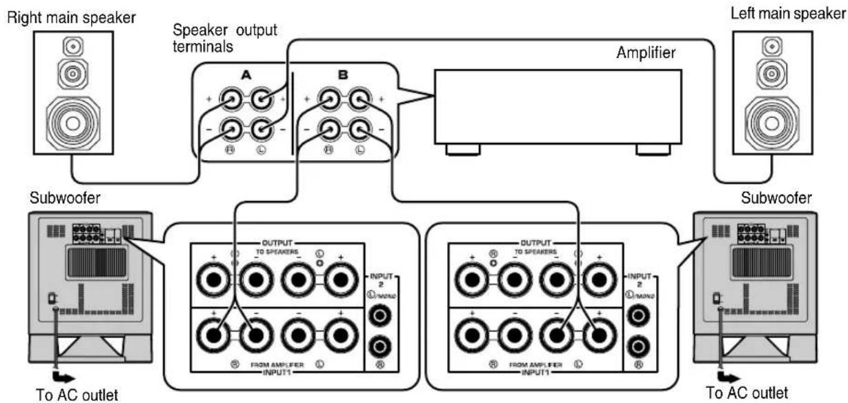
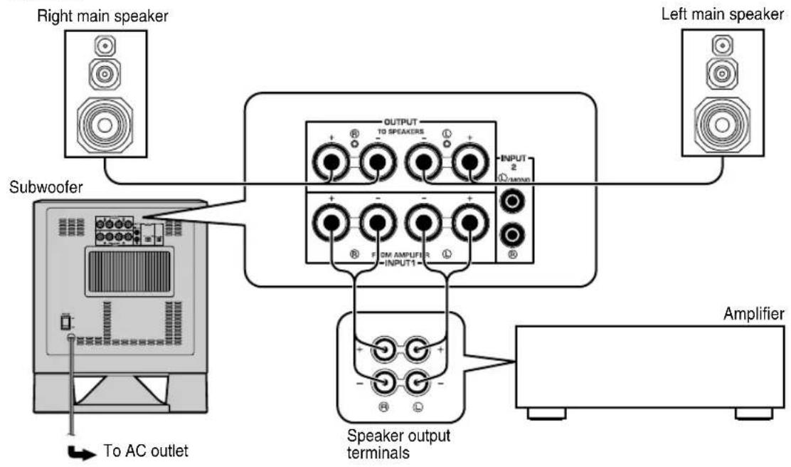
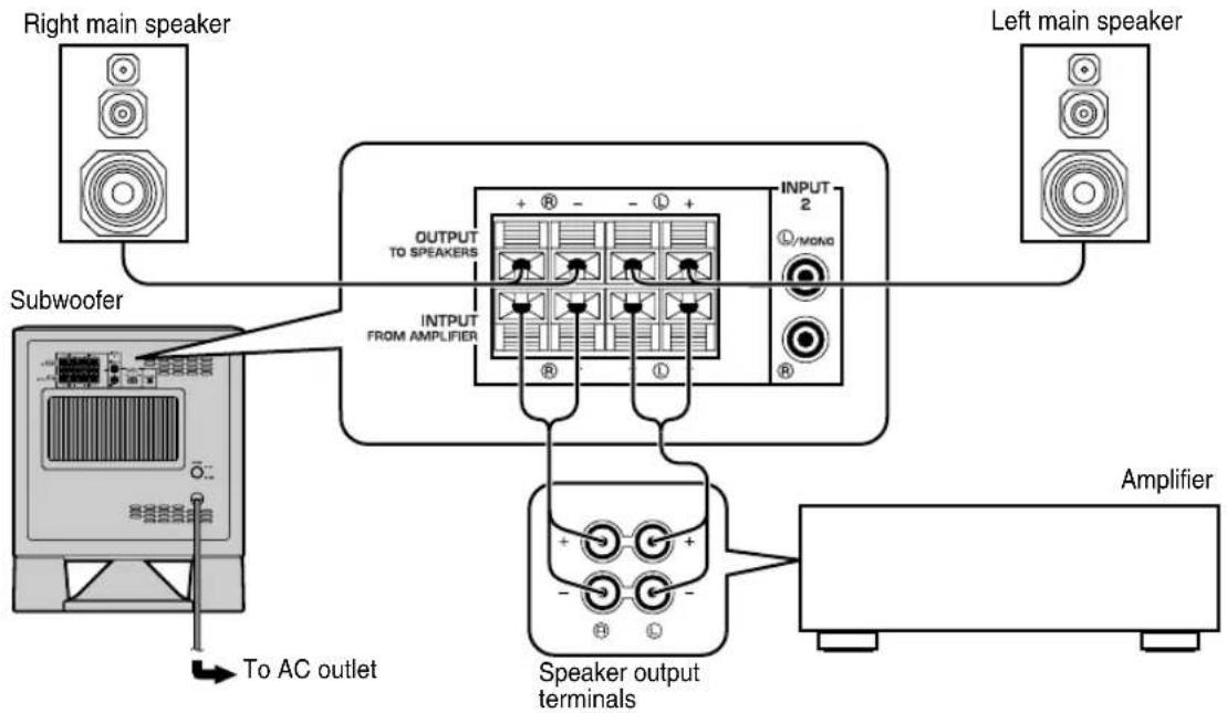
2 Connecting to speaker output terminals of the amplifier
Select this method if your amplifier has no line output (pin jack) terminal.
If your amplifier has two sets of main speaker output terminals and both terminals can output sound signals simultaneously.
- Connect one set of main speaker output terminals of the amplifier to the INPUT1 terminals of the subwoofer, and connect the other set of main speaker output terminals of the amplifier to the main speakers.
- Set the amplifier so that both sets of main speaker output terminals output sound signals simultaneously.
Note
- If your amplifier has only one set of main speaker output terminals, see page 10.
■ Using one subwoofer (with speaker cables)
flowchart
graph TD
    A["Right main speaker Subwoofer"] -->|To AC outlet| B["Speaker output terminals"]
    B --> C["Speaker output terminals A and B"]
    C --> D["Amplifier"]
    D --> E["Left main speaker"]
    style A fill:#f9f,stroke:#333
    style E fill:#bbf,stroke:#333
    style B fill:#ccf,stroke:#333
    style C fill:#cfc,stroke:#333
    style D fill:#fcc,stroke:#333
flowchart
graph TD
    A["Right main speaker"] --> B["Speaker output terminals"]
    C["Left main speaker"] --> D["Speaker output terminals"]
    B --> E["To AC outlet"]
    D --> F["Speaker output terminals"]
    E --> G["Subwoofer"]
    F --> H["Subwoofer"]
    G --> I["OUTPUT TO SPEAKERS"]
    G --> J["INPUT FROM AMPLIFIER"]
    H --> K["INPUT 2 L/MONG"]
    I --> L["Amplifier"]
    J --> L
    style A fill:#f9f,stroke:#333
    style C fill:#f9f,stroke:#333
    style D fill:#f9f,stroke:#333
    style G fill:#ccf,stroke:#333
    style H fill:#ccf,stroke:#333
    style I fill:#ccf,stroke:#333
    style J fill:#ccf,stroke:#333
    style K fill:#ccf,stroke:#333
    style L fill:#ccf,stroke:#333
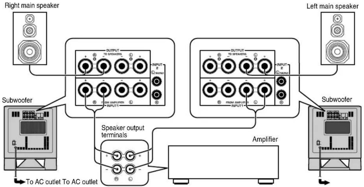
■ Using two subwoofers (with speaker cables)
flowchart
graph TD
    A["Right main speaker"] --> B["Speaker output terminals"]
    B --> C["Amplifier"]
    C --> D["Left main speaker"]
    E["Subwoofer"] --> F["OUTPUT TO SPEAKERS INPUT1"]
    F --> G["OUTPUT TO SPEAKERS INPUT2"]
    G --> H["To AC outlet"]
    I["Subwoofer"] --> J["OUTPUT TO SPEAKERS INPUT1"]
    J --> K["OUTPUT TO SPEAKERS INPUT2"]
    K --> L["To AC outlet"]
flowchart
graph TD
    A["Right main speaker"] --> B["Speaker output terminals"]
    B --> C["Amplifier"]
    C --> D["Left main speaker"]
    E["Subwoofer"] --> F["OUTPUT TO SPEAKERS INPUT FROM AMPUFER"]
    F --> G["OUTPUT TO SPEAKERS INPUT FROM AMPUFER"]
    G --> H["To AC outlet"]
    I["Left main speaker"] --> J["Amplifier"]
    J --> K["Output to AC outlet"]
    style A fill:#f9f,stroke:#333
    style E fill:#f9f,stroke:#333
    style I fill:#f9f,stroke:#333
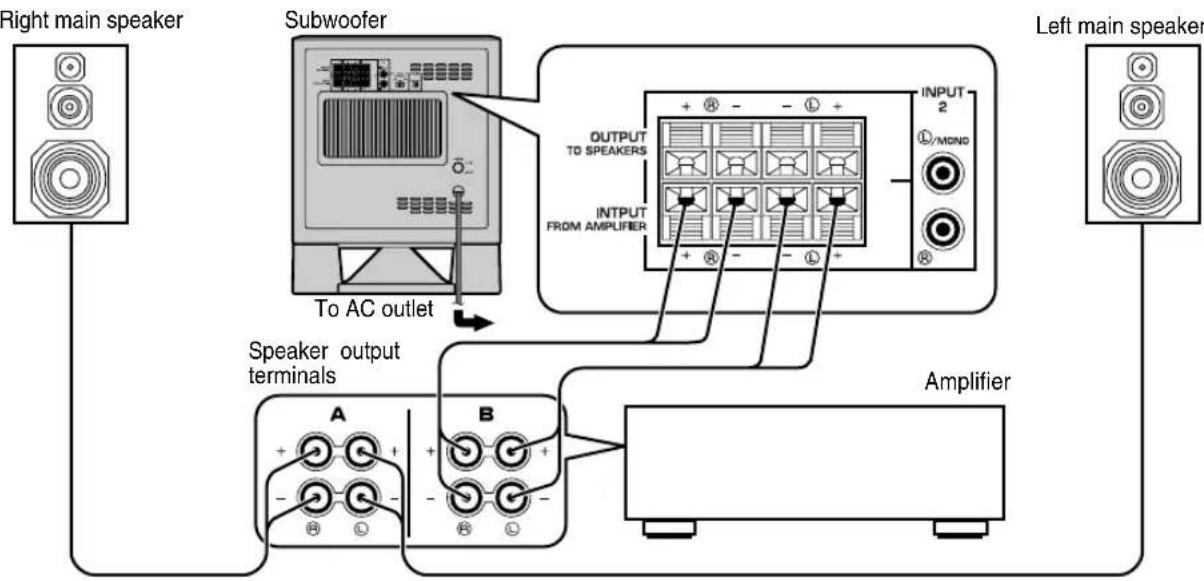
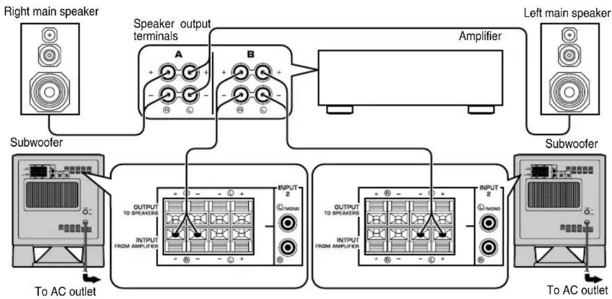
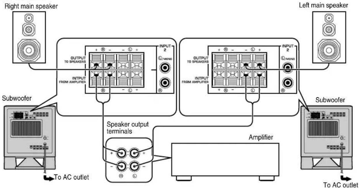
If your amplifier has only one set of main speaker output terminals.
Connect the speaker output terminals of the amplifier to the INPUT1 terminals of the subwoofer, and connect the OUTPUT terminals of the subwoofer to the main speakers.
■ Using one subwoofer (with speaker cables)
flowchart
graph TD
    A["Right main speaker"] --> B["Subwoofer"]
    C["Left main speaker"] --> B
    B --> D["Speaker output terminals"]
    D --> E["Amplifier"]
    style A fill:#f9f,stroke:#333
    style C fill:#f9f,stroke:#333
    style B fill:#ccf,stroke:#333
    style D fill:#cfc,stroke:#333
    style E fill:#fcc,stroke:#333
flowchart
graph TD
    A["Right main speaker"] --> B["Subwoofer"]
    C["Left main speaker"] --> D["Speaker output terminals"]
    E["Speaker output terminals"] --> F["Amplifier"]
    B --> G["OUTPUT TO SPEAKERS"]
    B --> H["INPUT FROM AMPLIFIER"]
    G --> I["+ - - +"]
    H --> J["+ - - +"]
    I --> K["OUTPUT TO SPEAKERS"]
    J --> L["OUTPUT FROM AMPLIFIER"]
    K --> M["INPUT 2 /MOND"]
    L --> N["INPUT 2 /MOND"]
    M --> O["To AC outlet"]
■ Using two subwoofers (with speaker cables)
flowchart
graph TD
    A["Right main speaker"] --> B["OUTPUT TO SPEAKERS"]
    B --> C["INPUT 2"]
    C --> D["Subwoofer"]
    D --> E["Speaker output terminals"]
    E --> F["To AC outlet To AC outlet"]
    G["Left main speaker"] --> H["OUTPUT TO SPEAKERS"]
    H --> I["INPUT 2"]
    I --> J["Subwoofer"]
    J --> K["Speaker output terminals"]
    K --> L["To AC outlet To AC outlet"]
    M["Amplifier"] --> N["Speaker output terminals"]
    N --> O["To AC outlet To AC outlet"]
flowchart
graph TD
    A["Right main speaker"] --> B["OUTPUT TO SPEAKERS"]
    B --> C["INPUT 2 /MOND"]
    C --> D["OUTPUT TO SPEAKERS"]
    D --> E["INPUT 2 /MOND"]
    E --> F["Left main speaker"]
    G["Subwoofer"] --> H["Speaker output terminals"]
    H --> I["Amplifier"]
    I --> J["To AC outlet"]
    K["To AC outlet"] --> L["Speaker output terminals"]
    L --> M["Amplifier"]
Connecting to the INPUT1/OUTPUT terminals of the subwoofer
For connection, keep the speaker cables as short as possible. Do not bundle or roll up the excess part of the cables. If the connections are faulty, no sound will be heard from the subwoofer or the speakers, or both of them. Make sure that the + and - polarity markings of the speaker cables are observed and set correctly. If these cables are reversed, the sound will be unnatural and lack bass.
Caution
Do not let the bare speaker wires touch each other, because this could damage the subwoofer or the amplifier, or both of them.
■Before connecting
Remove the insulation coating at the extremity of each speaker cable by twisting the coating off.

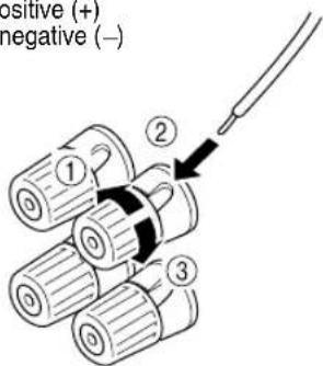
■How to connect:
①Loosen the terminal's knob, as shown in the figure.
②Insert the bare wire.
③Tighten the knob.
④Test the firmness of the connection by pulling lightly on the cable at the terminal.
Red: positive (+)
Black: negative (−)
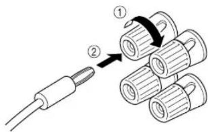
U.S.A., Canada and Australia models only
Banana Plug convection are also possible.
①Tighten the terminal knob.
②Simply insert the banana plug into the terminal.
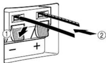
①Press and hold the terminal's tab, as shown in the figure.
②Insert the bare wire.
③Release your finger from the tab to allow it to lock securely on the cable's wire end.
④Test the firmness of the connection by pulling lightly on the cable at the terminal.
Red: positive (+)
Black: negative (−)
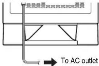
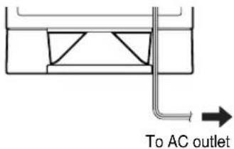
Plug in the subwoofer to the AC outlet
After all connections are completed, plug in the subwoofer and other audio/video components to the AC outlet.
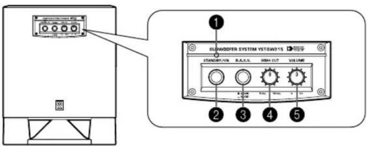
CONTROLS AND THEIR FUNCTIONS
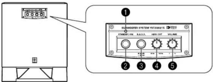
Front panel
Front panel
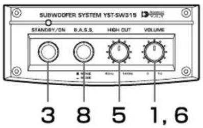
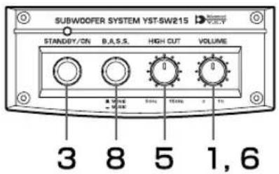
①Power indicator
Lights up in green while the subwoofer is on.
Lights up in red while the subwoofer is set in the standby mode by the operation of the automatic power-switching function.
Goes off when the subwoofer is set in the standby mode.
②STANDBY/ON button
Press this button to turn on the power when the POWER switch is set in the ON position. (The power indicator lights up in green.)
Press again to set the subwoofer in the standby mode. (The power indicator goes off.)
Standby mode
The subwoofer is still using a small amount of power in this mode.
③B.A.S.S. (Bass Action Selector System) button
When this button is pressed in to the MUSIC position, the bass sound in audio software is well reproduced.
By pressing the button again so that it pops out at the MOVIE position, the bass sound in video software is well reproduced.

MOVIE

MUSIC
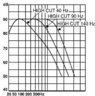
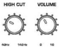
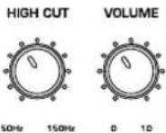
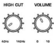
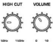
④ HIGH CUT control
Adjusts the high frequency cut off point.
Frequencies higher than the frequency selected by this control are all cut off (and no output).
* One graduation of this control represents 10 Hz.
⑤VOLUME control
Adjusts the volume level. Turn the control clockwise to increase the volume, and counterclockwise to decrease the volume.
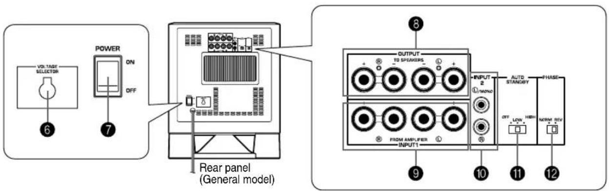
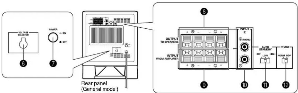
⑥ VOLTAGE SELECTOR switch
(China, Korea and General models only)
If the preset setting of the switch is incorrect, set the switch to the proper voltage (110V, 120V, 220V or 240V) of your area.
Consult your dealer if you are unsure of the correct setting.
WARNING
Be sure to unplug the subwoofer before setting the VOLTAGE SELECTOR switch correctly.
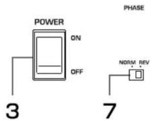
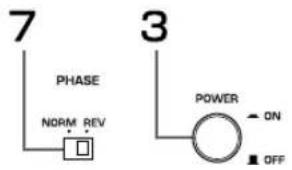
⑦ POWER switch
Normally, set this switch to the ON position to use the subwoofer. In this state, you can turn on the subwoofer or turn the subwoofer into the standby mode by pressing the STANDBY/ON button. Set this switch to the OFF position to completely cut off the subwoofer's power supply from the AC line.
⑧ OUTPUT (TO SPEAKERS) terminals
Can be used for connecting to the main speakers.
Signals from the INPUT1 terminals are sent to these terminals.
(Refer to "CONNECTIONS" for details.)
⑨ INPUT1 (FROM AMPLIFIER) terminals
Used to connect the subwoofer with the speaker terminals of the amplifier.
(Refer to "CONNECTIONS" for details.
⑩INPUT2 terminals
Used to input line level signals from the amplifier.
(Refer to "CONNECTIONS" for details.)
11 AUTO STANDBY (HIGH/LOW/OFF) switch
This switch is originally set to the OFF position. By setting this switch to the HIGH or LOW position, the subwoofer's automatic power-switching function operates as described on page 15. If you do not need this function, leave this switch in the OFF position.
* Make sure to change the setting of this switch only when the subwoofer is set in the standby mode by pressing the STANDBY/ON button.
⑫PHASE switch
Normally this switch is to be set to the REV (reverse) position. However, according to your speaker systems or the listening condition, there may be a case when better sound quality is obtained by setting this switch to the NORM (normal) position. Select the better position by monitoring the sound.
AUTOMATIC POWER-SWITCHING FUNCTION
If the source being played is stopped and the input signal is cut off for 7 to 8 minutes, the subwoofer automatically switches to the standby mode. (When the subwoofer switches to the standby mode by the automatic power-switching function, the power indicator lights up in red.)
When you play a source again, the power of the subwoofer turns on automatically by sensing audio signals input to the subwoofer.
This function operates by sensing a certain level of low frequency input signal. Usually set the AUTO STANDBY switch to the LOW position. However, if this function does not operate smoothly, set the switch to the HIGH position. In the HIGH position, the power will turn on even with a low level of input signal. But please be aware that the subwoofer may not switch to the standby mode when there is an extremely low input signal.
* The power might turn on unexpectedly by sensing noise from other appliances. If that occurs, set the AUTO STANDBY switch to the OFF position and use the STANDBY/ON button to switch the power between on and to the standby mode manually.
This function detects the low-frequency components below 200 Hz of the input signals (i.e., the explosion in the action movie, the sound of the bass guitar or the bass drum, etc.).
* The minutes required to switch the subwoofer to the standby mode might change by sensing noise from other appliances.
This function is available only when the power of the subwoofer is on (by pressing the STANDBY/ON button).
ADJUSTING THE SUBWOOFER BEFORE USE
Before using the subwoofer, adjust the subwoofer to obtain the optimum volume and tone balance between the subwoofer and the main speakers by following the procedures described below.
1 Set the VOLUME control to minimum (0).
2 Turn on the power of all the other components.
3 Make sure that the POWER switch is set to the ON position, then press the STANDBY/ON button to turn on the subwoofer.
* The Power indicator lights up in green.
4 Play a source containing low-frequency components and adjust the amplifier's volume control to the desired listening level.
5 Adjust the HIGH CUT control to the position where the desired response can be obtained.
Normally, set the control to the level a little higher than the main speaker's rated minimum reproducible frequency*.
* The main speaker's rated minimum reproducible frequency can be looked up in the speakers' catalog or owner's manual.
6 Increase the volume gradually to adjust the volume balance between the subwoofer and the main speakers. Normally, set the control to the level where you can obtain a little more bass effect than when the subwoofer is not used. If the desired response cannot be obtained, adjust the HIGH CUT control and the VOLUME control again.
7 Set the PHASE switch to the position which gives you the better bass sound.
Normally, set the switch to the REV (reverse) position. If the desired response cannot be obtained, set the switch to the NORM (normal) position.
8 Select "MOVIE" or "MUSIC" according to the played source.
MOVIE:
When a movie type source is played, the low-frequency effects are enhanced to allow the listeners enjoy more powerful sound. (The sound will be thicker and deeper.)
MUSIC:
When an ordinary music source is played, the excessive low-frequency components are cut off to make the sound clearer. (The sound will be lighter and reproduces the melody line more clearly.)
- Once the volume balance between the subwoofer and the main speakers is adjusted, you can adjust the volume of your whole sound system by using the amplifier's volume control.
However, if you change the main speakers to others, you must make this adjustment again.
- For adjusting the VOLUME control, the HIGH CUT control and the PHASE switch, refer to “Frequency characteristics” on page 17.
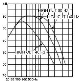
Frequency characteristics
This subwoofer's frequency characteristics
line
| Frequency | High Cut 40 Hz (dB) | High Cut 90 Hz (dB) | High Cut 140 Hz (dB) | | --------- | ------------------- | ------------------- | -------------------- | | 20 | 85 | 85 | 85 | | 50 | 90 | 88 | 88 | | 100 | 92 | 86 | 86 | | 200 | 93 | 84 | 84 | | 500 | 92 | 82 | 82 | | 1000 | 88 | 78 | 78 | | 2000 | 82 | 72 | 72 | | 5000 | 75 | 65 | 65 | | 10000 | 68 | 58 | 58 | | 20000 | 60 | 52 | 52 | | 50000 | 52 | 48 | 48 |
line
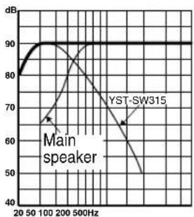
| Frequency | High Cut 90 Hz (dB) | High Cut 140 Hz (dB) | High Cut 40 Hz (dB) | | --------- | ------------------- | -------------------- | ------------------- | | 20 | 70 | 70 | 70 | | 50 | 85 | 85 | 65 | | 100 | 90 | 88 | 60 | | 200 | 90 | 88 | 55 | | 500 | 90 | 88 | 50 |The figures below show the optimum adjustment of each control and the frequency characteristics when this subwoofer is combined with a typical main speaker system.
■EX.1 When combined with a 4" or 5" (10 cm or 13 cm) acoustic suspension, 2 way system main speakers
PHASE :
Set to the
REV(reverse) position
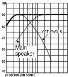
line
| Frequency | Main speaker | YST-SW315 | | --------- | ------------ | --------- | | 20 | 80 | 80 | | 50 | 85 | 75 | | 100 | 90 | 70 | | 200 | 90 | 65 | | 500 | 90 | 50 |
PHASE :
Set to the
REV(reverse) position
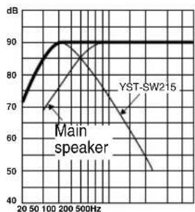
line
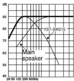
| Frequency | Main speaker (dB) | YST-SW215 (dB) | | --------- | ----------------- | -------------- | | 20 | 70 | 70 | | 50 | 75 | 75 | | 100 | 85 | 80 | | 200 | 90 | 85 | | 500 | 90 | 70 |■EX.2 When combined with an 8" or 10" (20 cm or 25 cm) acoustic suspension, 2 way system main speakers
PHASE :
Set to the
REV(reverse) position
line
| Frequency | Main speaker | YST-SW315 | | --------- | ------------ | --------- | | 20 | 80 | 80 | | 50 | 85 | 85 | | 100 | 90 | 90 | | 200 | 85 | 85 | | 500 | 70 | 70 | | 1000 | 60 | 60 | | 2000 | 50 | 50 | | 5000 | 45 | 45 |
PHASE :
Set to the
REV(reverse) position
line
| Frequency | Main speaker (dB) | YST-SW215 (dB) | | --------- | ----------------- | -------------- | | 20 | 70 | - | | 50 | 80 | - | | 100 | 90 | - | | 200 | 90 | - | | 500 | 90 | - |ADVANCED YAMAHA ACTIVE SERVO TECHNOLOGY
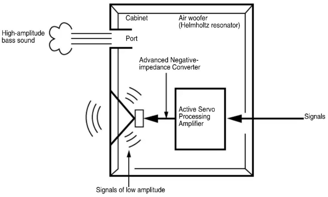
The theory of Yamaha Active Servo Technology has been based upon two major factors, the Helmholtz resonator and negative-impedance drive. Active Servo Processing speakers reproduce the bass frequencies through an “air woofer”, which is a port or opening in the speaker’s cabinet. This opening is used instead of, and performs the functions of, a woofer in a conventionally designed speaker system. Thus, signals of low amplitude within the cabinet can, according to the Helmholtz resonance theory, be outputted from this opening as waves of great amplitude if the size of the opening and the volume of the cabinet are in the correct proportion to satisfy a certain ratio.
In order to accomplish this, moreover, the amplitudes within the cabinet must be both precise and of sufficient power because these amplitudes must overcome the “load” presented by the air that exists within the cabinet.
Thus it is this problem that is resolved through the employment of a new design in which the amplifier supplies special signals. If the electrical resistance of the voice coil could be reduced to zero, the movement of the speaker unit would become linear with respect to signal voltage. To accomplish this, a special negative-impedance output-drive amplifier for subtracting output impedance of the amplifier is used.
By employing negative-impedance drive circuits, the amplifier is able to generate precise, low-amplitude, low-frequency waves with superior damping characteristics. These waves are then radiated from the cabinet opening as high-amplitude signals. The system can, therefore, by employing the negative-impedance output drive amplifier and a speaker cabinet with the Helmholtz resonator, reproduce an extremely wide range of frequencies with amazing sound quality and less distortion.
The features described above, then, are combined to be the fundamental structure of the conventional Yamaha Active Servo Technology.
Our new Active Servo Technology, Advanced Yamaha Active Servo Technology, adopted Advanced Negative Impedance Converter (ANIC) circuits, which allows the conventional negative impedance converter to dynamically vary in order to select an optimum value for speaker impedance variation. With this new ANIC circuits, Advanced Yamaha Active Servo Technology can provide more stable performance and improved sound pressure compared with the conventional Yamaha Active Servo Technology, resulting in more natural and dynamic bass reproduction.
flowchart
graph TD
    A["High-amplitude bass sound"] --> B["Port"]
    B --> C["Air woofer (Helmholtz resonator)"]
    C --> D["Active Servo Processing Amplifier"]
    D --> E["Signals"]
    D --> F["Advanced Negative-impedance Converter"]
    F --> G["Signals of low amplitude"]
    G --> H["Cabinet"]
TROUBLESHOOTING
Refer to the chart below when this unit does not function properly. If the problem you are experiencing is not listed below or if the instructions given below do not help, disconnect the power cord and contact your authorized YAMAHA dealer or service center.
| Problem Cause What to Do | ||
| Power is not supplied even though the STANDBY/ON button is set to the ON position. | The power plug is not securely connected. | Connect it securely. |
| The POWER switch is set to the OFF position. | Set the POWER switch to the ON position. | |
| No sound. The volume is set to minimum. | Raise the volume up. | |
| Speaker cables are not connected securely. | Connect them securely. | |
| Sound level is too low. Speaker cables are | not connected correctly. | Connect them correctly, that is L (left) to L, R (right) to R, “+” to “+” and “-” to “-”. |
| Setting of the PHASE switch is not proper. | Set the PHASE switch to the other position. | |
| A source sound with few bass frequencies is played. | Play a source sound with bass frequencies.Set the HIGH CUT control to a higher position. | |
| It is influenced by standing waves. Reposition on the subwoofer or break up the parallel surface by placing bookshelves etc. along the walls. | ||
| The subwoofer does not turn on automatically. | The POWER switch is set to the OFF position. | Set the POWER switch to the ON position. |
| The STANDBY/ON button is set to the OFF position. | Set the STANDBY/ON button to the ON position. | |
| The AUTO STANDBY switch is set to the OFF position. | Set the AUTO STANDBY switch to the “HIGH” or “LOW” position. | |
| The level of input signal is too low. Set the AUTO STANDBY switch to the “HIGH” position. | ||
| The subwoofer does not turn into the standby mode automatically. | There is an influence of noise generated from external appliances etc. | Move the subwoofer farther away from such appliances and/or reposition the connected speaker cables.Otherwise, set the AUTO STANDBY switch to the “OFF” position. |
| The AUTO STANDBY switch is set to the OFF position. | Set the AUTO STANDBY switch to the “HIGH” or “LOW” position. | |
| The subwoofer turns into the standby mode unexpectedly. | The level of input signal is too low. Set the AUTO STANDBY switch to the “HIGH” position. | |
| The subwoofer turns on unexpectedly. There is an influence of noise generated from external appliances etc. | Move the subwoofer farther away from such appliances and/or reposition the connected speaker cables.Otherwise, set the AUTO STANDBY switch to the “OFF” position. | |
SPECIFICATIONS
Type ...... Advanced Yamaha Active Servo Technology
Driver
Magnetic shielding type
Magnetic shielding type
Amplifier Output (100 Hz, 5 ohms, 10% THD)
Frequency Response
Power Supply
USA and Canada models ......AC 120V, 60 Hz
U.K. and Europe models ......AC 230V, 50 Hz
Australia model ......AC 240V, 50 Hz
China, Korea and General models
AC 110/120/220/240 V, 50/60 Hz
Power Consumption
Standby Power Consumption 0.5W
Dimensions (W x H x D)
(13-3/4" x 16-15/16" x 15-1/16")
(11-7/16" x 14-3/16" x 12-11/16")
Weight
Please note that all specifications are subject to change without notice.
ACCESSOIRES FOURNIS....3
POSITIONNEMENT....4
BRANCHEMENTS......5
flowchart
graph TD
    A["Square"] --> B["Arrow to bottom"]
    C["Square"] --> D["Arrow to top"]
    E["Square"] --> F["Arrow to bottom"]
B
flowchart
graph TD
    A["Gray Diamond"] --> B["White Square"]
    B --> C["Gray Diamond"]
    C --> D["White Square"]
    D --> E["Gray Diamond"]
    E --> F["Black Arrow Down"]
    F --> G["Black Arrow Up"]
    G --> H["Black Arrow Left"]
    H --> I["Black Arrow Right"]
    I --> J["Black Arrow Down"]
    J --> K["Black Arrow Up"]
    K --> L["Black Arrow Left"]
    L --> M["Black Arrow Right"]
C
flowchart
graph TD
    A[" "] --> C[" "]
    B[" "] --> C[" "]
    C --> D[" "]
natural_image
Technical line drawing of a washing machine with mounting holes and a close-up inset showing internal components (no text or symbols)BRANCHEMENTS
Type ...... Advanced Yamaha Active Servo Technology