ET260 - Measuring equipment Klein Tools - Free user manual and instructions
Find the device manual for free ET260 Klein Tools in PDF.
Download the instructions for your Measuring equipment in PDF format for free! Find your manual ET260 - Klein Tools and take your electronic device back in hand. On this page are published all the documents necessary for the use of your device. ET260 by Klein Tools.
USER MANUAL ET260 Klein Tools
- BUILT-IN TEST LEAD HOLDERS
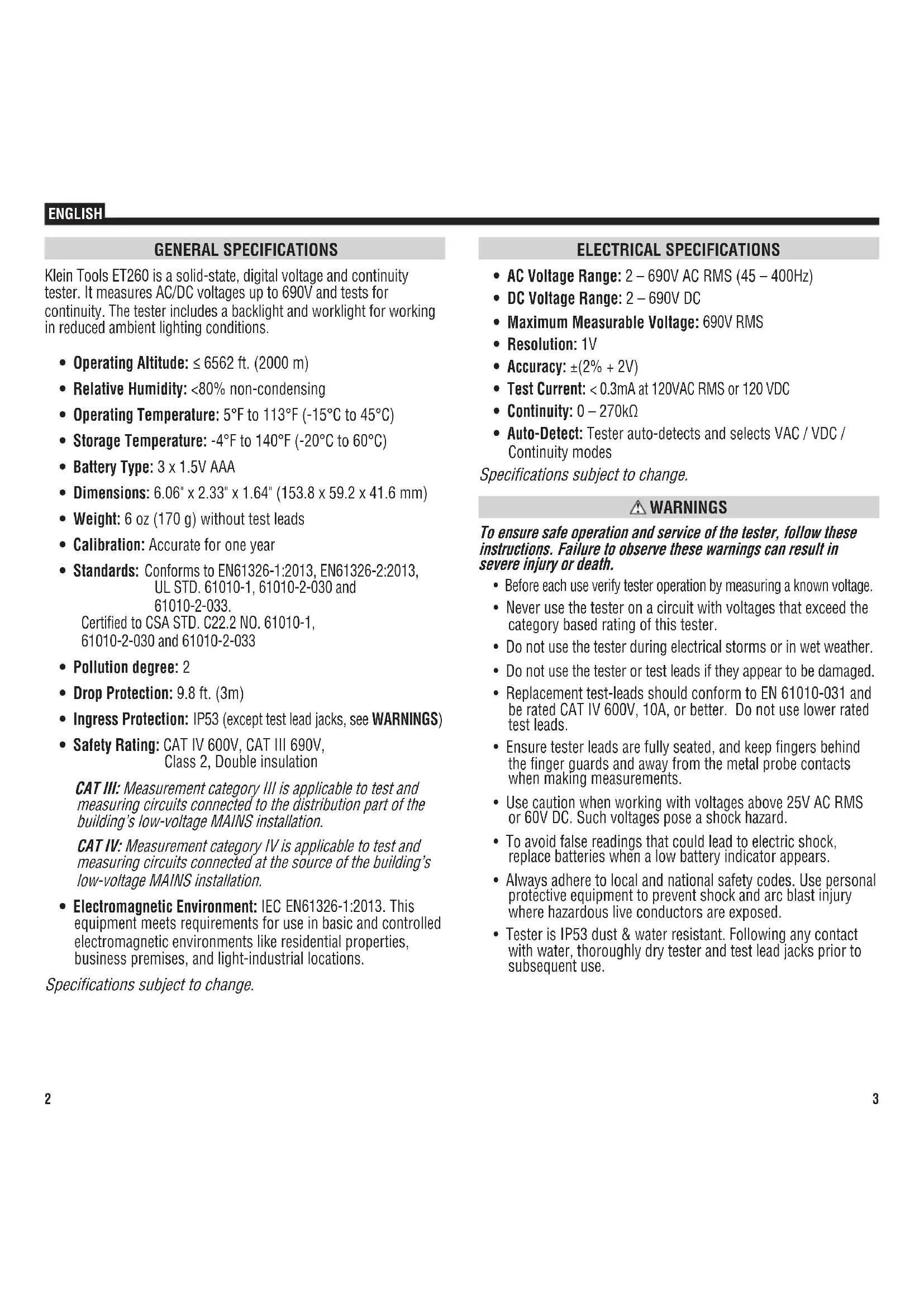
- BACKLIT LCD DISPLAY ENGLISH2 3 GENERAL SPECIFICATIONS Klein Tools ET260 is a solid-state, digital voltage and continuity tester. It measures AC/DC voltages up to 690V and tests for continuity. The tester includes a backlight and worklight for working in reduced ambient lighting conditions.
- Operating Altitude: ≤ 6562 ft. (2000 m)
- Relative Humidity: <80% non-condensing
- Operating Temperature: 5°F to 113°F (-15°C to 45°C)
- Storage Temperature: -4°F to 140°F (-20°C to 60°C)
- Weight: 6 oz (170 g) without test leads
- Calibration: Accurate for one year
- Drop Protection: 9.8 ft. (3m)
- Ingress Protection: IP53 (except test lead jacks, see WARNINGS)
- Safety Rating: CAT IV 600V, CAT III 690V, Class 2, Double insulation CAT III: Measurement category III is applicable to test and measuring circuits connected to the distribution part of the building’s low-voltage MAINS installation. CAT IV: Measurement category IV is applicable to test and measuring circuits connected at the source of the building’s low-voltage MAINS installation.
- Electromagnetic Environment: IEC EN61326-1:2013 . This equipment meets requirements for use in basic and controlled electromagnetic environments like residential properties, business premises, and light-industrial locations. Specifications subject to change. ENGLISH ELECTRICAL SPECIFICATIONS
- Maximum Measurable Voltage: 690V RMS
- Accuracy: ±(2% + 2V)
- Test Current: < 0.3mA at 120VAC RMS or 120 VDC
- Continuity: 0 – 270kΩ
- Auto-Detect: Tester auto-detects and selects VAC / VDC / Continuity modes Specifications subject to change. WARNINGS To ensure safe operation and service of the tester, follow these instructions. Failure to observe these warnings can result in severe injury or death.
- Before each use verify tester operation by measuring a known voltage.
- Never use the tester on a circuit with voltages that exceed the category based rating of this tester.
- Do not use the tester during electrical storms or in wet weather.
- Do not use the tester or test leads if they appear to be damaged.
- Replacement test-leads should conform to EN 61010-031 and be rated CAT IV 600V, 10A, or better. Do not use lower rated test leads.
- Ensure tester leads are fully seated, and keep fingers behind the finger guards and away from the metal probe contacts when making measurements.
- Use caution when working with voltages above 25V AC RMS or 60V DC. Such voltages pose a shock hazard.
- To avoid false readings that could lead to electric shock, replace batteries when a low battery indicator appears.
- Always adhere to local and national safety codes. Use personal protective equipment to prevent shock and arc blast injury where hazardous live conductors are exposed.
- Tester is IP53 dust & water resistant. Following any contact with water, thoroughly dry tester and test lead jacks prior to subsequent use.4 5 INCORRECT CORRECT OPERATING INSTRUCTIONS
CONNECTING TEST LEADS
USE PROPER SAFETY-RATED TEST LEADS
Connect test leads by inserting the black lead into the "COM" jack and the red lead into the "+" jack. Do not test if leads are improperly seated. Results could cause intermittent display readings. To ensure proper connection, firmly press leads into the input jack completely.
Positive Lead Input COM Common / Negative Lead InputDouble Insulated Class II GroundWarning or CautionRisk of Electrical Shock
Indicates presence of voltage > 50V AC or DC VAC AC VoltageAudible Continuity VDC DC VoltageLow Battery IndicatorWorklight ENGLISH FEATURE DETAILS NOTE: There are no user-serviceable parts inside tester.
Test Lead Jacks (bottom of tester) Back of Tester
FUNCTION BUTTONS POWER-ON/OFF: Press the On/Off button to turn the tester on or off. The tester will automatically power-ON if test leads are applied to a circuit and it detects voltage >12V. The tester will automatically power-OFF following 15 minutes of inactivity to conserve battery life. BACKLIGHT: Press the Backlight button to turn on/off the backlight. The backlight will automatically power off after 3 minutes of inactivity to conserve battery life. FLASHLIGHT: Press the Flashlight button to turn on/off the Flashlight. The flashlight will remain on until turned off or tester powers off.
OPERATING INSTRUCTIONS CONTINUITY Remove power from circuit. Test for continuity by applying test leads to the system being tested. The tester automatically enters continuity testing mode. If resistance < 270kΩ is detected, an audible signal will sound and the continuity icon "
" will show in the display indicating continuity. If the circuit is open, "
" will show in the display.
DO NOT attempt to measure continuity on a live circuit. AC/DC VOLTAGE (LESS THAN 690V) Apply test leads to the system under test to measure voltage; the voltage measured will be reflected in the display. The tester will automatically detect the presence of AC or DC voltage and illuminate the appropriate icon in the display.
AUTION: The maximum testing voltage is 690V. ‘OL’ will show in the display if voltage in excess of 690V is detected. No other warnings will be delivered for voltages above 690V. Testing voltages above 690V should not be attempted under any circumstances. ENGLISH OPERATING INSTRUCTIONS TESTING IN CAT III / CAT IV MEASUREMENT LOCATIONS Ensure the test lead shield is pressed firmly in place. Failure to use the CATIII / CATIV shield increases arc-flash risk.
TESTING IN CAT II MEASUREMENT LOCATIONS
CAT III / CAT IV shields may be removed for CAT II locations. This will allow testing on recessed conductors such as standard wall outlets. Take care not to lose the shields. 5/32" (4 mm) .7" (18 mm) MAINTENANCE BATTERY REPLACEMENT When the Low Battery indicator shows low battery strength ( ), batteries must be replaced.
1. Remove 2 screws from battery door.
2. Replace 3 x 1.5V AAA batteries (note proper polarity).
3. Replace battery door and fasten securely with screws.
o avoid risk of electric shock, disconnect leads from any voltage source before removing battery door. To avoid risk of electric shock, do not operate tester while battery door is removed. NOTE: There are no user-serviceable parts inside tester.8 CLEANING Disconnect test leads. Clean the instrument by using a damp cloth. Do not use abrasive cleaners or solvents. STORAGE Do not expose to high temperatures or humidity. After a period of storage in extreme conditions exceeding the limits mentioned in the General Specifications section, allow the instrument to return to normal operating conditions before use. WARRANTY www.kleintools.com/warranty DISPOSAL / RECYCLE Do not place equipment and its accessories in the trash. Items must be properly disposed of in accordance with local regulations. Please see www.epa.gov or www.erecycle.org for additional information. CUSTOMER SERVICE KLEIN TOOLS, INC. 450 Bond Street Lincolnshire, IL 60069 1-877-775-5346customerservice@kleintools.com www.kleintools.comENGLISH ET260 ESPAÑOL