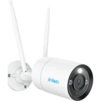
USER MANUAL RLC810WA REOLINK
If you need any technical help, please visit our official support site and contact our support team before returning the products,
https://support.reolink.com.
CET PRODUCT SERVICE SP. Z O.O.
UI. Dluga 33 102 Zgierz, Polen
UK REP
CET PRODUCT SERVICE LTD.
Beacon House Stokenchurch Business Park, Ibstone Rd, Stokenchurch High Wycombe, HP14 3FE, UK
January 2024
QSG2_A
58.03.006.0106A
reolink
Be Prepared, Be Reolink
EN/DE/FR/IT/ES
Item No.: W330/W430
Operational Instruction
Apply to: RLC-810WA, RLC-811WA

@ReolinkTech https://reolink.com
EN
Contents
What's in the Box 2
Camera Introduction 3
Connection Diagram 5
Set up the Camera 6
Mount the Camera 7
Troubleshooting....11
Specifications 12
Notification of Compliance 13
What's in the Box
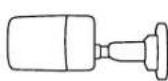
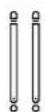
Camera Antenna Power Adapter
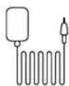
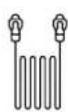
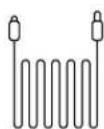
1m Network Cable Mounting 4.5m Power Extension Cable
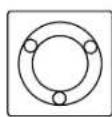
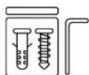
Pack of Screws
Surveillance Sign
Template
Quick Start Guide
NOTE: Camera and accessories vary with different camera models that you purchase.
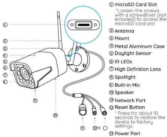
Camera Introduction
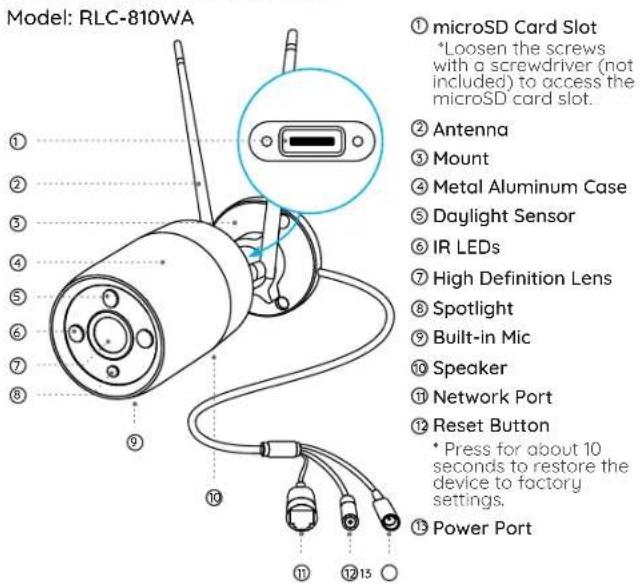
EnglishEnglish3 4
Model: RLC-811WA
Connection Diagram
Before initial setup, follow the steps below to connect your camera.
- Connect the camera to a LAN port on your router with an Ethernet cable.
- Power on the camera with a power adapter.
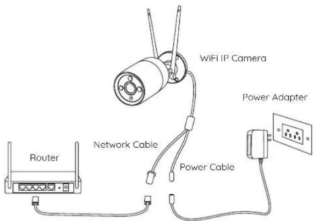
EnglishEnglish5 6
Set up the Camera
Download and Launch the Realink App or Client software, and follow the onscreen instructions to finish initial setup.
NOTE: You can now use WiFi instead of the Ethernet cable for network connection.
- On Smartphone
Scan to download the Reolink App.


- On PC
Download path of the Reolink Client: Go to https://reolink.com > Support > App & Client.
NOTE: If you are connecting the camera to a Reolink PoE NVR, please set up the camera via the NVR Interface.
Mount the Camera
Installation Tips
- Do not face the camera towards any light sources.
- Do not point the camera towards a glass window. Or, it may result in poor image quality because of the window glare by infrared LEDs, ambient lights or status lights.
- Do not place the camera in a shaded area and point it towards a well-lit area. Or, it may result in poor image quality. To ensure best image quality, the lighting condition for both the camera and the capture object shall be the same.
- To ensure better image quality, it's recommended to clean the lens with a soft cloth from time to time.
- Make sure the power ports are not directly exposed to water or moisture and not blocked by dirt or other elements.
- With IP waterproof ratings, the camera can work properly under conditions like rain and snow. However, it doesn't mean the camera can work underwater.
- Do not install the camera at places where rain and snow can hit the lens directly.
- The camera may work in extreme cold conditions as low as -10^ . Because when it is powered on, the camera will produce heat. You may power on the camera indoors for a few minutes before installing it outdoors.
NOTE: There are two different types of mounts for bullet cameras. Please check out the mount included in the package and follow the corresponding instruction to install the camera properly.
Install the Camera
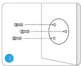
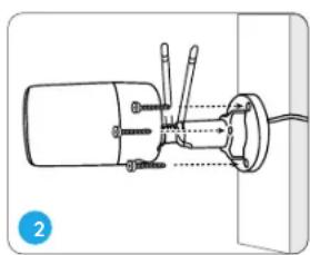
Drill holes in accordance with the mounting hole template.
NOTE: Use the drywall anchors included in the package if needed.
natural_image
Technical line drawing of a mechanical assembly with no visible text or symbols
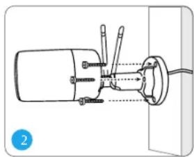
Install the mount base with the mounting screws included in the package.
NOTE: Run the cable through the cable notch on the mount base.
natural_image
Illustration of a hand holding a cylindrical object with a tool, showing a blue arrow indicating rotation (no text or symbols present)
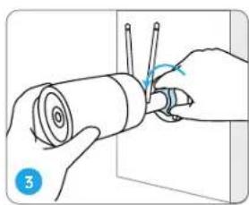
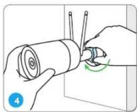
To get the best field of view, loosen the adjustment knob on security mount and turn the camera.
natural_image
Illustration of hands holding a cylindrical object with a green circular arrow indicating rotation (no text or symbols)
Stiffen the adjustment knob to lock the camera.
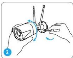
NOTE: If your camera has another mount without the adjusting knob, please loosen the adjusting screw with the provided hex key and turn the camera as shown below to adjust the angle.
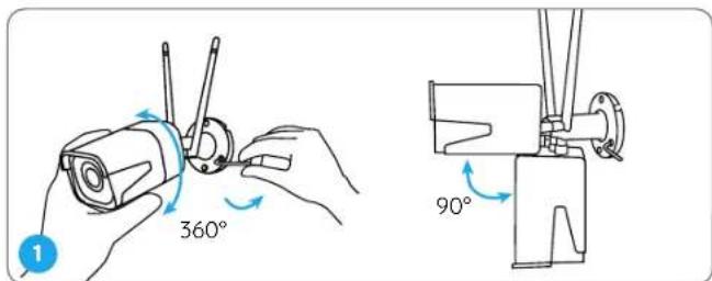
Twist the screws with the wrench to unlock the camera and adjust its direction.
natural_image
Illustration of hands performing a mechanical manipulation or disassembly task (no text or symbols present)
After adjustment, twist the screws back to lock the camera.
Troubleshooting
Camera is not Powering on
If you find your camera is not powering on, try the following solutions:
- Please check whether the outlet is working properly or not. Try to plug the camera into a different outlet and see if it works.
- Please check whether the DC adapter is working or not. If you have another 12V DC power adapter which is working, please use another power adapter and see if it works.
If these won't work, contact Reolink Support https://support.reolink.com/.
Infrared LEDs Stop Working
If the Infrared LEDs of your camera stop working, please try the following solutions:
- Enable infrared lights on Device Settings page via Reolink App/Client.
- Check if the Day/Night mode is enabled and set up auto infrared lights at night on Live View page via Reolink App/Client.
- Upgrade the firmware of your camera to the latest version.
- Restore the camera to factory settings and check out the infrared light settings again.
If these won't work, contact Reolink Support https://support.reolink.com/.
EnglishEnglish11 12
Failed to Upgrade the Firmware
If you fail to upgrade the firmware for the camera, try the following solutions:
- Check out the current camera firmware and see if it is the latest one.
- Make sure that you download the correct firmware from Download Center.
- Make sure that your PC is working on a stable network.
If these won't work, contact Reolink Support https://support.reolink.com/.
Specifications
General
Operating Temperature: -10°C to 55°C (14°F to 131°F)
Operating Humidity: 10%-90%
RLC-810WA Size: Φ67 x 187mm
RLC-811WA Size: 80 x 72 x 238mm
(Weight: 485.7g, for RLC-810WA)
Weight: 862.9, for RLC-811WA)
For more Specifications, visit https://reolink.com/.
Notification of Compliance
FCC Compliance Statements
This device complies with Part 15 of the FCC Rules. Operation is subject to the following two conditions: (1) this device may not cause harmful interference, and (2) this device must accept any interference received, including interference that may cause undesired operation.
Note: This equipment has been tested and found to comply with the limits for a Class B digital device, pursuant to Part 15 of the FCC Rules. These limits are designed to provide reasonable protection against harmful interference in a residential installation. This equipment generates, uses and can radiate radio frequency energy and, if not installed and used in accordance with the instructions, may cause harmful interference to radio communications. However, there is no guarantee that interference will not occur in a particular installation. If this equipment does cause harmful interference to radio or television reception, which can be determined by turning the equipment off and on, the user is encouraged to try to correct the interference by one or more of the following measures:
- Reorient or relocate the receiving antenna.
- Increase the separation between the equipment and receiver.
- Connect the equipment into an outlet on a circuit different from that to which the receiver is connected.
- Consult the dealer or an experienced radio/TV technician for help.
Caution: Changes or modifications not expressly approved by the party responsible for compliance could void the user's authority to operate the equipment.
FCC Radiation Exposure statement
This equipment complies with FCC radiation exposure limits set forth for an uncontrolled environment. This equipment should be installed and operated with minimum distance 20cm between the radiator and your body.
ISED Compliance Statements
This device contains licence-exempt transmitter(s)/receiver(s) that comply with Innovation, Science and Economic Development Canada's licence-exempt RSS(s). Operation is subject to the following two conditions:
ISED Radiation Exposure statement
This equipment complies with IC RSS-102 radiation exposure limits set forth for an uncontrolled environment. This equipment should be installed and operated with minimum distance 20 cm between the radiator and your body.
Reolink declares that this device is in compliance with the essential requirements and other relevant provisions of Directive 2014/53/EU and Directive 2014/30/EU.
WiFi Operating Frequency
The functions of Wireless Access Systems Including Radio Local Area Networks(WAS/RLANs) within the band 5150-5350 MHz for this device are restricted to indoor use only within all European
Union countries (BE/BG/CZ/DK/DE/EE/IE/EL/ES/FR/HR/IT/CY/LV/LT/LU/HU/MT/NL/AT/PL/PT/RO/SI/SK/FI/SE/TR/N O/CH/IS/LI/UK(NI)

Correct Disposal of This Product
This marking indicates that this product should not be disposed with other household wastes, throughout the EU. To prevent possible harm to the environment or human health from uncontrolled waste disposal, recycle it responsibly to promote the sustainable reuse of material resources. To return your used device, please use the return and collection systems or contact the retailer where the product was purchased. They can take this product for environmentally safe recycling.
Limited Warranty
This product comes with a 2-year limited warranty that is valid only if purchased from Reolink Official Store or a Reolink authorized reseller. Learn more: https://reolink.com/warranty-and-return/.
Terms and Privacy
Use of the product is subject to your agreement to the Terms of Service and Privacy Policy at reolink.com. Keep out of reach of children.
Technical Support
If you need any technical help, please visit our official support site and contact our support team before returning the products: https://support.reolink.com.
DE
Katalog
Lieferumfang 20
Über die Kamera 21
① microSD-Kartenslot
① microSD-Kartenslot
natural_image
Technical line drawing of a mechanical assembly with no visible text or symbols
natural_image
Illustration of a hand holding a cylindrical object with a tool inserted, showing a blue arrow indicating rotation (no text or symbols present)
natural_image
Illustration of hands holding a cylindrical device with wires and a green circular arrow indicating rotation (no text or symbols)
natural_image
Illustration of hands performing a mechanical manipulation or disassembly task (no text or symbols present)
natural_image
Technical line drawing of a mechanical assembly with no visible text or symbols
natural_image
Illustration of a hand holding a cylindrical object with a tool, showing a blue arrow indicating rotation (no text or symbols present)
natural_image
Illustration of hands holding a cylindrical object with a green circular arrow indicating rotation (no text or symbols)
natural_image
Illustration of hands performing a mechanical manipulation or disassembly task (no text or symbols present)
Assistance technique
natural_image
Technical diagram of a mechanical assembly with no visible text or symbols
natural_image
Illustration of a hand holding a rolled-up cylindrical object with a tool inserted, showing a blue arrow indicating rotation (no text or symbols present)
natural_image
Illustration of hands holding a cylindrical object with wires, no text or symbols present
natural_image
Illustration of hands performing a mechanical manipulation or disassembly task (no text or symbols present)
Ulteriori informazioni: https://reolink.com/warranty-and-return/.
Termini e Privacy
natural_image
Technical line drawing of a mechanical assembly with no visible text or symbols
natural_image
Illustration of a hand holding a cylindrical object with a tool, showing a blue arrow indicating rotation (no text or symbols present)
natural_image
Illustration of hands holding a cylindrical object with a green circular arrow indicating rotation (no text or symbols)
natural_image
Illustration of hands holding a cylindrical device with rotating blades (no text or symbols)