
RA972 - Receiver ROTEL - Free user manual and instructions
Find the device manual for free RA972 ROTEL in PDF.
| Product Type | Integrated Stereo Receiver |
| Continuous Power Output | 60 W/channel (20 - 20,000 Hz, 8 ohms, THD < 0.03%) |
| Total Harmonic Distortion | < 0.03% (20 - 20,000 Hz, max power, 1/2 power or 1 watt) |
| Intermodulation Distortion | < 0.03% (60 Hz : 7 kHz, 4:1) |
| Frequency Response | 10 Hz - 100 kHz (+1 dB, -3 dB) |
| Damping Factor | 150 (20 - 20,000 Hz, 8 ohms) |
| Input Sensitivity / Impedance | 160 mV / 33 kΩ |
| Input Overload | 5 V |
| Preamp Output / Impedance | 1 V / 470 Ω |
| Bass and Treble Controls | ±6 dB at 100 Hz / 10 kHz |
| Signal-to-Noise Ratio | > 95 dB (A-weighted IHF) |
| Power Supply | 115 V/60 Hz (USA version) or 230 V/50 Hz (EU version) |
| Number of Line Inputs | 5 (CD, Tuner, Tape 1, Tape 2, Aux) |
| Speaker Outputs | 2 pairs (A and B), min impedance 4 Ω (one pair) or 8 Ω (two pairs) |
| Headphone Jack | 6.35 mm stereo jack |
| 12 V Trigger Output | 3.5 mm jack for automatic power on |
| Remote Control | RR-AT92 (infrared): volume, mute, standby, source selection |
| Maintenance | Dry cloth or small vacuum; do not use liquid products |
| Placement | On a flat, rigid surface; leave 10 cm clearance around for ventilation |
| Safety | Unplug before cleaning; do not obstruct ventilation slots |
| Warranty | Fill out and return warranty card; keep receipt |
| Special Features | Independent listening and recording selectors; toroidal transformer |
Frequently Asked Questions - RA972 ROTEL
User questions about RA972 ROTEL
0 question about this device. Answer the ones you know or ask your own.
Ask a new question about this device
Download the instructions for your Receiver in PDF format for free! Find your manual RA972 - ROTEL and take your electronic device back in hand. On this page are published all the documents necessary for the use of your device. RA972 by ROTEL.
USER MANUAL RA972 ROTEL
natural_image
Close-up of a printed circuit board with various electronic components and traces (no readable text or symbols)
Owner's Manual Manuel d'utilisation Bedienungsanleitung Manuale di Istruzioni Manual de Instrucciones Gebruiksaanwijzing
RA-972
Stereo Integrated Amplifier Amplificateur Intégré Stéréophonique Stereo-Vollverstärker Amplificatore Integrato Estereofonico Amplificador Integrado Estereofónico Geïntegreerde Stereo Versterker

CAUTION
RISK OF ELECTRIC SHOCK DO NOT OPEN

CAUTION: TO REDUCE THE RISK OF ELECTRIC SHOCK, DO NOT REMOVE COVER. NO USER-SERVICEABLE PARTS INSIDE. REFER SERVICING TO QUALIFIED SERVICE PERSONNEL.
APPLICABLE FOR USA, CANADA OR WHERE APPROVED FOR THE USAGE
CAUTION: TO PREVENT ELECTRIC SHOCK, MATCH WIDE BLADE OF PLUG TO WIDE SLOT. INSERT FULLY.
ATTENTION: POUR EVITER LES CHOCS ELECTRIQUES, INTRODUIRE LA LAME LA PLUS LARGE DE LA FICHE DANS LA BORNE CORRESPONDANTE DE LA PRISE ET POUSSER JUSQU AU FOND.
This symbol is to alert the user to the presence of uninsulated dangerous voltages inside the product's enclosure that may constitute a risk of electric shock.

This symbol is to alert the user to important operating and maintenance (service) instructions in this manual and literature accompanying the product.
WARNING: There are no user serviceable parts inside. Refer all servicing to qualified service personnel.
WARNING: To reduce the risk of fire or electric shock, do not expose the unit to moisture or water. Do not allow foreign objects to get into the enclosure. If the unit is exposed to moisture, or a foreign object gets into the enclosure, immediately disconnect the power cord from the wall. Take the unit to a qualified service person for inspection and necessary repairs.
Read all the instructions before connecting or operating the component. Keep this manual so you can refer to these safety instructions.
Heed all warnings and safety information in these instructions and on the product itself. Follow all operating instructions.
Clean the enclosure only with a dry cloth or a vacuum cleaner.
You must allow 10 cm or 4 inches of unobstructed clearance around the unit. Do not place the unit on a bed, sofa, rug, or similar surface that could block the ventilation slots. If the component is placed in a bookcase or cabinet, there must be ventilation of the cabinet to allow proper cooling.
Keep the component away from radiators, heat registers, stoves, or any other appliance that produces heat.
The unit must be connected to a power supply only of the type and voltage specified on the rear panel of the unit.
Connect the component to the power outlet only with the supplied power supply cable or an exact equivalent. Do not modify the supplied cable in any way. Do not attempt to defeat grounding and/or polarization provisions. Do not use extension cords.
Do not route the power cord where it will be crushed, pinched, bent at severe angles, exposed to heat, or damaged in any way. Pay particular attention to the power cord at the plug and where it exits the back of the unit.
The power cord should be unplugged from the wall outlet if the unit is to be left unused for a long period of time.
Immediately stop using the component and have it inspected and/or serviced by a qualified service agency if:
- The power supply cord or plug has been damaged.
- Objects have fallen or liquid has been spilled into the unit.
• The unit has been exposed to rain.
• The unit shows signs of improper operation
• The unit has been dropped or damaged in any way
Place the unit on a fixed, level surface strong enough to support its weight. Do not place it on a moveable cart that could tip over.

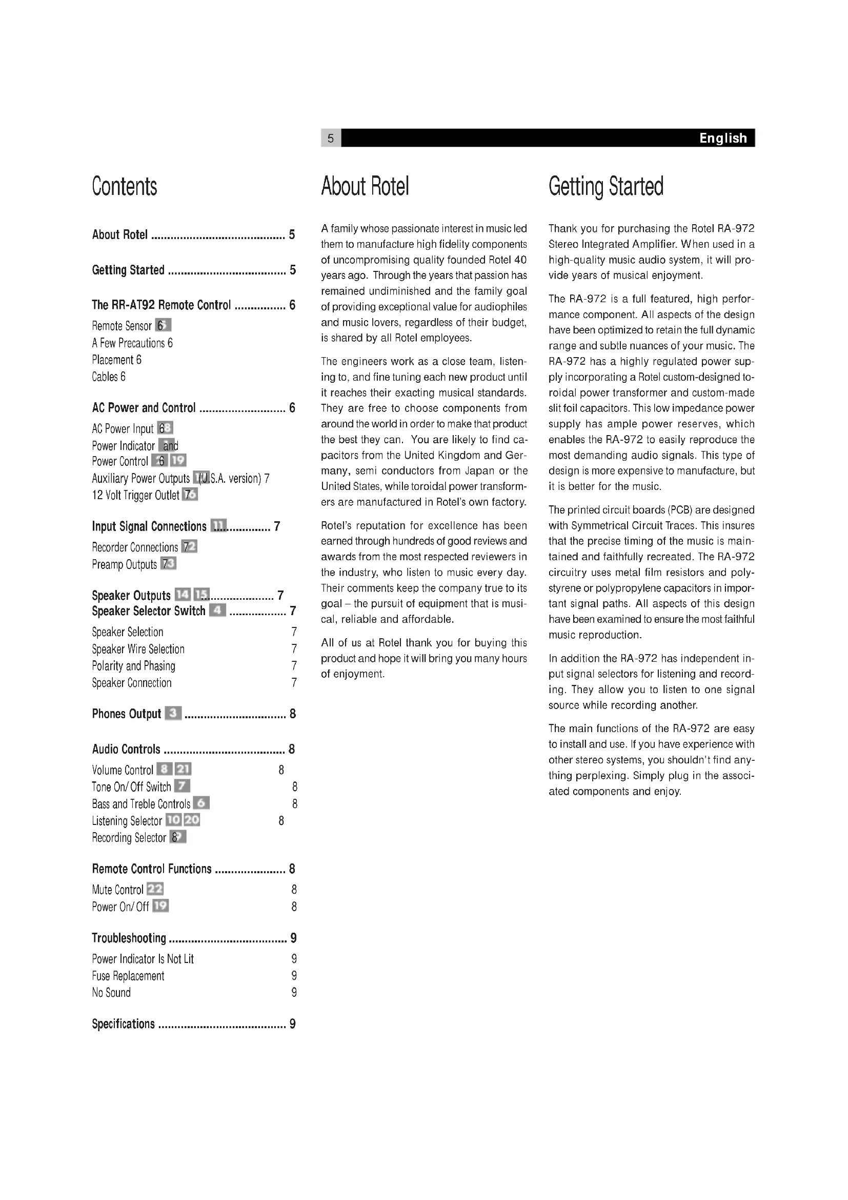
Figure 1: Controls and Connections
Figure 2: Line Level Signal, Recorder and Speaker Output Connection
Contents
About Rotel 5
Getting Started 5
The RR-AT92 Remote Control 6
Remote Sensor 6
A Few Precautions 6
Placement 6
Cables 6
AC Power and Control 6
AC Power Input 68
Power Indicator and
Power Control 6 19
Auxiliary Power Outputs (U.S.A. version) 7
12 Volt Trigger Outlet 76
Input Signal Connections 11......7
Recorder Connections 72
Preamp Outputs 73
Speaker Outputs 14 15....7
Speaker Selector Switch 4 7
Speaker Selection 7
Speaker Wire Selection 7
Polarity and Phasing 7
Speaker Connection 7
Phones Output 3 8
Audio Controls 8
Volume Control 8 21 8
Tone On/Off Switch 7 8
Bass and Treble Controls 6 8
Listening Selector 10 20 8
Recording Selector 8
Remote Control Functions 8
Mute Control 22 8
Power On/Off 19 8
Troubleshooting 9
Power Indicator Is Not Lit 9
Fuse Replacement 9
No Sound 9
Specifications 9
About Rotel
A family whose passionate interest in music led them to manufacture high fidelity components of uncompromising quality founded Rotel 40 years ago. Through the years that passion has remained undiminished and the family goal of providing exceptional value for audiophiles and music lovers, regardless of their budget, is shared by all Rotel employees.
The engineers work as a close team, listening to, and fine tuning each new product until it reaches their exacting musical standards. They are free to choose components from around the world in order to make that product the best they can. You are likely to find capacitors from the United Kingdom and Germany, semi conductors from Japan or the United States, while toroidal power transformers are manufactured in Rotel's own factory.
Rotel's reputation for excellence has been earned through hundreds of good reviews and awards from the most respected reviewers in the industry, who listen to music every day. Their comments keep the company true to its goal – the pursuit of equipment that is musical, reliable and affordable.
All of us at Rotel thank you for buying this product and hope it will bring you many hours of enjoyment.
Getting Started
Thank you for purchasing the Rotel RA-972 Stereo Integrated Amplifier. When used in a high-quality music audio system, it will provide years of musical enjoyment.
The RA-972 is a full featured, high performance component. All aspects of the design have been optimized to retain the full dynamic range and subtle nuances of your music. The RA-972 has a highly regulated power supply incorporating a Rotel custom-designed toroidal power transformer and custom-made slit foil capacitors. This low impedance power supply has ample power reserves, which enables the RA-972 to easily reproduce the most demanding audio signals. This type of design is more expensive to manufacture, but it is better for the music.
The printed circuit boards (PCB) are designed with Symmetrical Circuit Traces. This insures that the precise timing of the music is maintained and faithfully recreated. The RA-972 circuitry uses metal film resistors and polystyrene or polypropylene capacitors in important signal paths. All aspects of this design have been examined to ensure the most faithful music reproduction.
In addition the RA-972 has independent input signal selectors for listening and recording. They allow you to listen to one signal source while recording another.
The main functions of the RA-972 are easy to install and use. If you have experience with other stereo systems, you shouldn't find anything perplexing. Simply plug in the associated components and enjoy.
The RR-AT92 Remote Control
Some functions can be done with either the front panel controls, or the supplied RR-AT92 remote control. When these operations are described, the call out number for both controls is shown. For example, you can select the source you want to listen to with either the front panel Listening Selector 10 or the remote control buttons 20.
Remote Sensor 5
The Remote Sensor picks up the infrared signals from the remote control. Do not cover or block the sensor. It must be unobstructed or the remote control will not work properly. The operation of the Remote Sensor can also be affected if it is exposed to bright light, particularly sunlight. Certain types of lighting, such as halogen lights, that emit a fair amount of infrared light, can also interfere with proper operation. In addition remote control functions may not work reliably if the batteries in the RR-AT92 are weak.
Note: Remove the batteries from the remote control if it will not be used for a long period of time. Do not leave run down batteries in the remote control. Exhausted batteries can leak corrosive chemicals which will damage the unit.
A Few Precautions
WARNING: To avoid potential damage to your system, turn off ALL the components in the system when connecting or disconnecting the loudspeakers or any associated components. Do not turn the system components back on until you are sure all the connections are correct and secure. Pay particular attention to the speaker wires. There must be no loose strands that could contact the other speaker wires, or the chassis of the amplifier.
Please read this manual carefully. It provides information on how to incorporate the RA-972 into your system as well as information that will help you get optimum sound performance. Please contact your authorized Rotel dealer for answers to any questions you might have. In addition, all of us at Rotel welcome your questions and comments.
Save the RA-972 shipping carton and all enclosed packing material for future use. Shipping or moving the RA-972 in anything other than the original packing material may result in severe damage to your amplifier.
Fill out and send in the owner's registration card packed with the RA-972. Also be sure to keep the original sales receipt. It is your best record of the date of purchase, which you will need in the event warranty service is ever required.
Placement
Like all audio components that handle low-level signals, the RA-972 can be affected by its environment. Avoid placing the RA-972 on top of other components. Also avoid routing audio signal cables near power cords. This will minimize the chance it will pick up hum or interference.
The RA-972 generates heat as part of its normal operation. The heat sinks and ventilation openings in the amplifier are designed to dissipate this heat. The ventilation slots in the top cover must be open. There should be 10 cm (4 inches) of clearance around the chassis, and reasonable airflow through the installation location, to prevent the amplifier from overheating.
Remember the weight of the amplifier when you select an installation location. Make sure that the shelf or cabinet can support it. We recommend installing the RA-972 in furniture designed to house audio components. Such furniture is designed to reduce or suppress vibration which can adversely affect sound quality. Ask your authorized Rotel dealer for advice about component furniture and proper installation of audio components.
Cables
Be sure to keep the power cords, digital signal cables and regular audio signal cables in your installation away from each other. This will minimize the chance of the regular audio signal cables picking up noise or interference from the power cords or digital cables. Using only high quality, shielded cables will also help to prevent noise or interference from degrading the sound quality of your system. If you have any questions see your authorized Rotel dealer for advice about the best cable to use with your system.
AC Power and Control
AC Power Input 18
Because of its relatively high power rating, the RA-972 can draw considerable current. Therefore, it should be plugged directly into a 2-pin polarized wall outlet. Do not use an extension cord. A heavy duty multi-tap power outlet strip may be used if it (and the wall outlet) is rated to handle the current demanded by the RA-972 and all the other components connected to it.
Your RA-972 is configured at the factory for the proper AC line voltage in the country where you purchased it (either 115 volts AC or 230 volts AC with a line frequency of either 50 Hz or 60 Hz). The AC line configuration is noted on a decal on the back panel.
Note: Should you move your RA-972 amplifier to another country, it is possible to reconfigure it for use on a different line voltage. Do not attempt to perform this conversion yourself. Opening the enclosure of the RA-972 exposes you to dangerous voltages. Consult a qualified service person or the Rotel factory service department for information.
If you are going to be away from home for an extended period of time such as a month-long vacation, it is a sensible precaution to unplug your amplifier (as well as other audio and video components) while you are away.
Power Indicator and Power Control 2 19
Press the front panel Power Switch button, to turn the RA-972 on. The Power Indicator light is illuminated when the RA-972 is on. Press Power button again to turn the RA-972 off.
Once the RA-972 has been turned on with the front panel power switch, it can be switched between normal operating mode and standby mode with the Power button 19 on the RR-AT92 remote control. See page 8 for more information
Auxiliary Power Outputs 17 (U.S.A. version)
The RA-972 has a switched outlet on the back panel. Power is available from this outlet when the RA-972 is turned on. The outlet can provide up to 400 watts. It is appropriate for supplying power to a signal source, such as a CD player, tuner, or tape deck. It should not be used for power amplifiers. Connecting a component that will draw more than 400 watts from this output could damage the Power Standby switch in the RA-972.
12 Volt Trigger Outlet 16
Some audio components can be turned on automatically when they receive a 12V turn on "signal". The 12V Trigger Output of RA-972 provides the required signal. Connect the compatible components to the RA-972 with a conventional 1/8" miniplug cable.
Input Signal Connections 11
[See Figure 2 for input connection illustration.]
The RA-972 has conventional RCA type input connectors, the type found on nearly all audio equipment.
Note: To prevent loud noises that neither you nor your speakers will appreciate, make sure the system is turned off when you make any signal connections.
All the inputs of the RA-972 are "line level" inputs. These are appropriate for connecting components such as CD players, Hi Fi or NICAM Stereo video cassette recorders, tuners for audio or video, Laser Disc players or the analog output from a CD ROM drive. If you want to use a phonograph with the RA-972, an external phono equalizer, such as the Rotel RQ-970BX must be used.
The Left and Right channels are clearly labeled and should be connected to the corresponding channels of the source component. The Left RCA connectors are white, the Right connectors are red. Use high quality RCA cables for connecting input source components to the RA-972. Ask your authorized Rotel dealer for advice about cables.
Recorder Connections 12
[See Figure 2 for recorder connection illustration.]
The Tape 1 and Tape 2 inputs and outputs can be connected to any record/ playback device that accepts standard line level analog input and output signals. Typically that will be a conventional tape recorder.
When connecting a recorder to the RA-972 remember that the outputs of the recorder must be connected to the tape inputs of the RA-972. Similarly the tape outputs of the RA-972 must be connected to the inputs of the recorder. As with other sources be sure to connect the Left and Right channels of each device to the proper channels on the associated components. Use high quality connecting cables to prevent loss of sound quality.
Preamp Outputs 13
The RA-972 has a set of preamp outputs. The signal from the source selected with the Listening Selector is always available from these outputs. Typically these outputs are used to provide a signal to another integrated amplifier or power amplifier, which is used to drive remote speakers
Speaker Outputs 14 15 Speaker Selector Switch 4
[See Figure 2 for speaker connection illustration.]
The RA-972 has two sets of speaker outputs, labeled "A" 14 and "B" 1. The speaker outputs are controlled by the switch 4 on the front panel.
Speaker Selection
If only one set of speakers will be used at any given time, the speakers may have an impedance as low as 4 ohms. If there are times when both the A and B speakers will be used, all the speakers should have an impedance of 8 ohms or more. Speaker impedance ratings are less than precise. In practice, very few loudspeakers will present any problems for the RA-972. See your authorized Rotel dealer if you have any questions.
Speaker Wire Selection
Use insulated two-conductor stranded wire to connect the RA-972 to the speakers. The size and quality of the wire can have an audible effect on the performance of the system. Standard speaker wire will work, but can result in lower output or diminished bass response, particularly over longer distances. In general, heavier wire will improve the sound. For best performance, you may want to consider special high-quality speaker cables. Your authorized Rotel dealer can help in the selection of cables for your system.
Polarity and Phasing
The polarity – the positive/negative orientation of the connections – for every speaker and amplifier connection must be consistent so all the speakers will be in phase. If the polarity of one connection is reversed, bass output will be very weak and stereo imaging degraded. All wire is marked so you can identify the two conductors. There may be ribs or a stripe on the insulation of one conductor. The wire may have clear insulation with different color conductors (copper and silver). There may be polarity indications printed on the insulation. Identify the positive and negative conductors and be consistent with every speaker and amplifier connection.
Speaker Connection
Turn off all the components in the system before connecting the speakers. The RA-972 has color-coded binding post type speaker connectors on the back panel (except in European Community countries where their use is not permitted). These connectors accept bare wire, connector lugs, or dual banana type connectors.
Route the wire from the RA-972 to the speakers. Give yourself enough slack so you can move the components to allow access to the speaker connectors. If you are using dual banana plugs, connect them to the wires and then plug into the backs of the binding posts. The thumbscrews of the binding posts should be screwed in all the way (clockwise).
If you are using terminal lugs, connect them to the wires. If you are attaching bare wires directly to the binding posts, separate the wire conductors and strip the insulation from the end of each conductor. Be careful not to cut into the wire strands. Unscrew (turn counterclockwise) the binding post thumbscrews. Place the connector lug or wire around the binding post shaft. Turn the thumbscrews clockwise to clamp the connector lug or wire firmly in place.
Note: Be sure there are no loose wire strands that could touch adjacent wires or connectors.
Phones Output 3
The Phones output allows you to connect headphones for private listening. This output accommodates standard stereo phone (1/4") plugs. If your headphones have another type of plug, such as a 1/8" mini-plug, you will need an adapter plug. Contact your authorized Rotel dealer, to get the correct adapter plug. Plugging in a set of headphones does not cut off the signal to the outputs. Use the Speaker Selector to turn off the speakers. The setting of the Listening Selector controls which source is heard. Turn the front panel Listening Selector to the source you want to listen to. Or press the corresponding source button on the remote control.
Note: Because the sensitivity of speakers and headphones can vary widely, always reduce the volume level before connecting or disconnecting headphones.
Audio Controls
Volume Control 8 21
Turn the controls clockwise to increase the volume, or counterclockwise to decrease the volume. Or use the remote control volume buttons. Press the ▲ button to increase the volume, or the ▼ button to decrease the volume.
Tone On/ Off Switch 7
When the Tone Switch is in the Off position the Bass and Treble Control (Tone Control) circuits are bypassed to ensure the purest possible sound. Leave the Tone Switch in the Off position unless you want to use the Tone Controls. Turn the Tone Switch to the On position if you want to adjust the Tone Controls.
Bass and Treble Controls 6
When the Tone Switch is in the On position, turning the Bass and Treble Controls adjusts the tone balance of the sound. Turn the Controls clockwise to increase the bass or treble output. Turn the Controls counterclockwise to decrease the bass or treble output.
A properly set up high-performance audio system produces the most natural sound with little or no adjustment of the tone controls. Use these controls sparingly. Be particularly careful when turning the controls up (clockwise). This increases the power output in the bass or treble range, increasing the load on the amplifier and speakers.
Listening Selector 10 20
The setting of the Listening Selector controls which of the input signals goes to the main outputs and onto the power amplifier—or, more simply, which source is heard. Turn the front panel Listening Selector to the source you want to listen to. Or press the corresponding source button on the remote control.
Recording Selector 9
The setting of the Recording Selector controls which of the input signals goes to the record outputs. When you are not recording, set the Recording Selector to the Off position to minimize the chance of interference from other components in the system.
Having a separate Recording and Listening selector adds a significant degree of flexibility in how you can use the RA-972. For example by setting the Record Selector to CD and the Listening Selector to Tuner you could record a CD onto a tape while listening to the tuner.
There is no Tape 2 position on the Recording Selector. Consequently, if you wish to duplicate ("dub") a recording from one recorder to another, the source unit must be connected to Tape 1 input. Set the Recording Selector to Tape 1. Connect the unit recording the signal to the Tape 2 output.
Remote Control Functions
Mute Control 22
To temporarily mute the sound of the system press the Mute Button on the RR-AT92 remote. The volume Control LED blinks when the sound is muted. Press the button again to return the sound volume to the original level.
Power On/Off 19
When the front panel Power switch is on, the RA-972 can be put in Standby mode by pressing the Power button on the remote. The LEDs in the Volume control and the Function selector will turn off. Press the Standby button again to return the unit to normal operating mode.
NOTE: The RR-AT92 can be used to operate the basic function of other certain other Rotel components, including Tuners, CD Players and DVD Players.
To operate a Rotel Tuner —
1) Select the tuner function of the RR-AT92.
2) Press "Power" and "1" (RT-955) or "2" (RT-940AX).
3) Press the key for Tuner operation.
To operate a Rotel CD Player — Select the CD function of the RR-AT92
To operate a Rotel DVD Player — Select the AUX 1 function of the RR-AT92.
Troubleshooting
Most difficulties in audio systems are the result of incorrect connections, or improper control settings. If you encounter problems, isolate the area of the difficulty, check the control settings, determine the cause of the fault and make the necessary changes. If you are unable to get sound from the RA-972 refer to the suggestions for the following conditions:
Power Indicator Is Not Lit
The Power Indicator should be lit whenever the RA-972 is plugged into the wall power outlet and the Power Switch is pushed in. If it does not light, test the power outlet with another electrical device, such as a lamp. Be sure the power outlet being used is not controlled by a switch that has been turned off.
Fuse Replacement
If another electrical device works when plugged into the power outlet, but the Standby Indicator still will not light when the RA-972 is plugged into the wall outlet, it indicates that the internal power fuse may have blown. If you believe this has happened, contact your authorized Rotel dealer to get the fuse replaced.
No Sound
Check the signal source to see if it is functioning properly. Make sure the cables from the signal source to the RA-972 inputs are connected properly. Be sure the Listening Selector is set to the proper input. Check the wiring between the RA-972 and the speakers.
Specifications
Continuous Power Output 60 watts/ch
(20-20 kHz, < 0.03%, 8 ohms)
Total Harmonic Distortion (20Hz-20kHz) < 0.03% at rated power,
1/2 power or 1 watt
Intermodulation Distortion (60 Hz : 7 kHz, 4:1) < 0.03% at rated power,
1/2 power or 1 watt
Frequency Response - all Inputs 10Hz-100kHz, +1, -3dB
Damping Factor (20-20,000 Hz, 8 ohms) 150
Input Sensitivity / Impedance 160 mV / 33 kOhms
Input Overload 5 V
Preamplifier Output / Impedance 1V / 470 ohms
Tone Controls - Bass / Treble ±6 dB at 100Hz / 10kHz
Signal to Noise Ratio (IHF "A" weighted) >95 dB
Power Requirements
USA Version 115 Volts, 60 Hz
European Version 230 Volts, 50 Hz
Power Consumption 300 Watts
Dimensions (W x H x D) 440 x 92 x 347 mm
173/8 × 55/8 × 1311/16"
Weight (net) 6.5 kg, 14.3 lbs.
All specifications are accurate at the time of printing.
Rotel reserves the right to make improvements without notice.
ATTENTION : POUR RÉDUIRE LE RISQUE D'ÉLECTROCUTION, NE PAS RETIRER LE CAPOT. IL N'Y A À L'INTÉRIEUR AUCUNE PIÈCE SUSCEPTIBLE D'ÊTRE MODIFIÉE PAR L'UTILISATEUR. EN CAS DE PROBLÈME, ADRESSEZ-VOUS À UN RÉPARATEUR AGRÉE.
Commandes audio.... 14
230 volts, 50 Hz (Europe)
Consommation 300 watts maximum
Dimensions (L x H x P) 440 x 92 x 347 mm
Poids (net) 6,5 kg
±6 dB a 100 Hz/10 kHz
natural_image
Close-up of a printed circuit board with various electronic components and traces (no readable text or symbols)
The Rotel Co. Ltd.
10-10 Shinsen-Cho
Shibuya-Ku
Tokyo 150-0045
Japan
Phone: +81 3-5458-5325
Fax: +81 3-5458-5310
Rotel of America
54 Concord Street
North Reading, MA 01864-2699
USA
Phone: +1 978-664-3820
Fax: +1 978-664-4109
Rotel Europe
Meadow Road
Worthing, West Sussex BN11 2RX
England
Phone: +44 (0)1903 524 813
Fax: +44 (0)1903 524 831
Rotel Deutschland
Kleine Heide 12
D-33790 Halle/ Westf.
Germany
Phone: +49 05201-87170
Fax: +49 05201-73370
www.rotel.com
- Owner's Manual Manuel d'utilisation Bedienungsanleitung Manuale di Istruzioni Manual de Instrucciones Gebruiksaanwijzing
- RA-972
- CAUTION
- APPLICABLE FOR USA, CANADA OR WHERE APPROVED FOR THE USAGE
- Contents
- About Rotel
- Getting Started
- The RR-AT92 Remote Control
- Remote Sensor 5
- A Few Precautions
- Placement
- Cables
- AC Power and Control
- AC Power Input 18
- Power Indicator and Power Control 2 19
- Auxiliary Power Outputs 17 (U.S.A. version)
- Volt Trigger Outlet 16
- Input Signal Connections 11
- [See Figure 2 for input connection illustration.]
- Recorder Connections 12
- [See Figure 2 for recorder connection illustration.]
- Preamp Outputs 13
- Speaker Outputs 14 15 Speaker Selector Switch 4
- [See Figure 2 for speaker connection illustration.]
- Speaker Selection
- Speaker Wire Selection
- Polarity and Phasing
- Speaker Connection
- Phones Output 3
- Audio Controls
- Volume Control 8 21
- Tone On/ Off Switch 7
- Bass and Treble Controls 6
- Listening Selector 10 20
- Recording Selector 9
- Remote Control Functions
- Mute Control 22
- Power On/Off 19
- To operate a Rotel Tuner —
- Troubleshooting
- Power Indicator Is Not Lit
- Fuse Replacement
- No Sound
- Specifications
Brand : ROTEL
Model : RA972
Category : Receiver