LI5041 - Sensor IFM - Free user manual and instructions
Find the device manual for free LI5041 IFM in PDF.
Download the instructions for your Sensor in PDF format for free! Find your manual LI5041 - IFM and take your electronic device back in hand. On this page are published all the documents necessary for the use of your device. LI5041 by IFM.
USER MANUAL LI5041 IFM
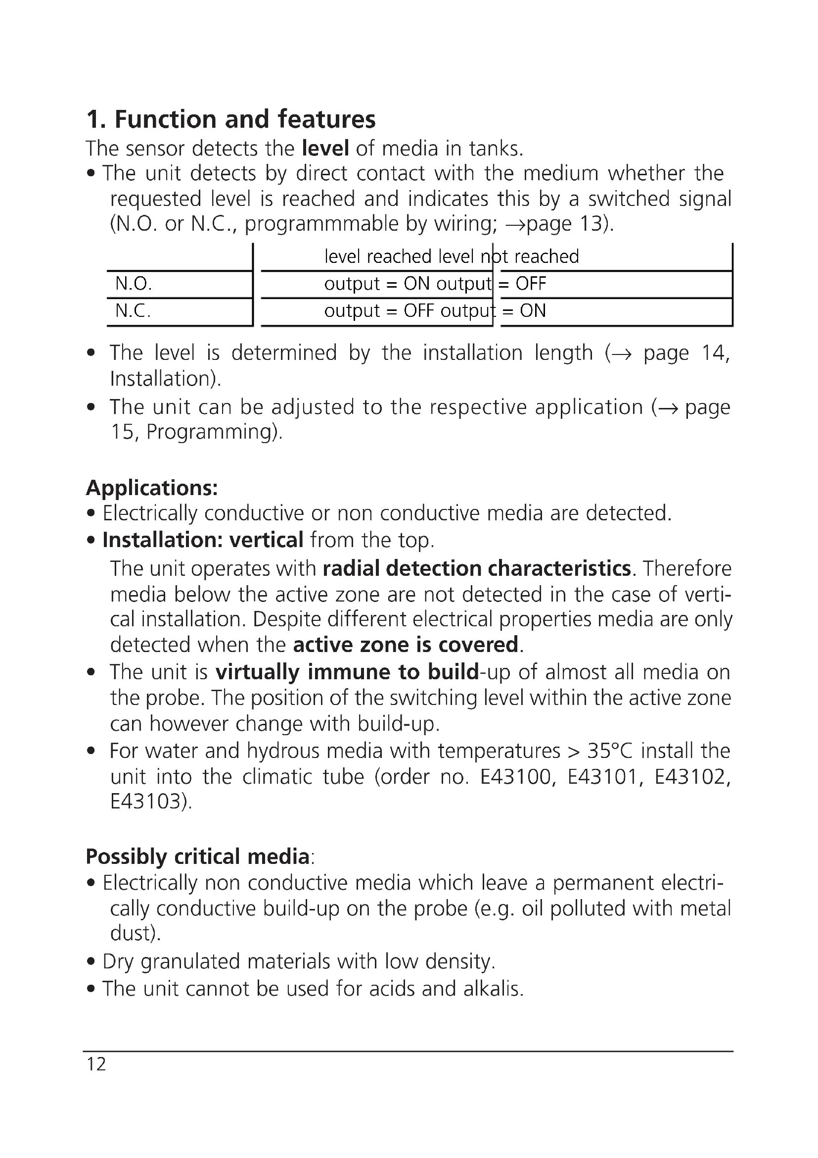
- The unit detects by direct contact with the medium whether the requested level is reached and indicates this by a switched signal (N.O. or N.C., programmmable by wiring; → page 13).
- The level is determined by the installation length (→ page 14, Installation).
- The unit can be adjusted to the respective application (→ page 15, Programming). Applications:
- Electrically conductive or non conductive media are detected.
- Installation: vertical from the top. The unit operates with radial detection characteristics. Therefore media below the active zone are not detected in the case of verti- cal installation. Despite different electrical properties media are only detected when the active zone is covered.
- The unit is virtually immune to build-up of almost all media on the probe. The position of the switching level within the active zone can however change with build-up.
- For water and hydrous media with temperatures > 35°C install the unit into the climatic tube (order no. E43100, E43101, E43102, E43103). Possibly critical media:
- Electrically non conductive media which leave a permanent electri- cally conductive build-up on the probe (e.g. oil polluted with metal dust).
- Dry granulated materials with low density.
- The unit cannot be used for acids and alkalis.
N.O. N.C. level reached level not reached output = ON output = OFF output = OFF output = ON2. Installation Mount the unit vertical from the top. Mounting length (L3): minimum 60mm. For safe and easy mounting use the ifm mounting accessories (Order no. E43000 - E43006). Maximum vessel pressure when mounted with mounting acces- sories: 0.5bar.
- If possible, mount the unit in the middle of the tank when it is installed in small plastic tanks:
- When installed in metal tanks the distance between sensor and tank wall / tank bottom must be min. 20mm.
A = response level H = height of the tank SH = height of the neck L = probe length (probe) L1 = installation length L2 = outside length L3 = mounting length MET = maximum immersion depth (= active zone, 25mm)• When several LI5 units are mounted in one tank minimum distances between them must be maintained. These depend on the medium and the respective application. Approximate values for common media: *Distance from the centreline of a probe to the centreline of ano- ther probe. The approximate values refer to standard operating conditions. Depending on the application greater distances can be required. Check this by means of a realistic function test (→ “5. Installation and set-up / operation”).
- Distance between sensors type LI5xxx and LKxxxx: min. 60mm from the centreline of a probe to the centreline of another probe.
3. Electrical connection
The unit must only be connected by an electrician. The national and international regulations for the installation of electrical equipment must be observed. Disconnect power before connecting the unit, ( = N.O. / = N.C.):
Core colours of ifm sockets: 1 = BN (brown), 3 = BU (blue), 4 = BK (black). Distance* 40mmWater / coolant emulsions in a grounded metal tank 100mmOils in a grounded metal tank 200mm Water, hydrous media and oils in a small plastic tank (ungrounded)4. Programming After mounting you must adjust the unit to the empty tank (empty adjustment).
- During the empty adjustment the unit determines a measured value for the empty state,
- automatically generates a hypothetical value for the full state (from the measured value for the empty state and a factory predefined signal difference).
- It then sets the optimum switching threshold between the two val- ues. The unit is then ready for operation.
Press the programming button until the green LED flashes (= the unit is in the adjustment mode). After adjustment the green LED is lit continuously ( the unit is in the operating mode).* Empty the tank until the material is min. 20mm away from the active zone.
max. 5s *If the unit is connected as NC, the yellow LED is also lit after adjustment.For an optimum adjustment of the unit to your application it is recommended to carry out a full adjustment in addition to an empty adjustment. It is recommended to carry out a full adjustment as well.
- During the full adjustment the unit adopts the measured value for the empty state determined during the empty adjustment,
- determines a measured value for the full state and
- sets the optimum switching threshold between the two values. This ensures an optimum adjustment of the unit to your appli- cation. You can repeat the full adjustment as often as you wish. The stored value for the empty state is not overwritten by the full adjustment. When an empty adjustment is made again the previously defined values are overwritten/replaced by the newly determined values. So always carry out the empty adjustment first, then the full adjustment.
*If the unit is connected as NC, the yellow LED goes out after adjustment.
Press the programming button until the green LED flashes quickly (= the unit is in the adjustment mode). The LED first flashes slowly (about 1Hz), after 5s it flashes double as quickly (about 2Hz). After adjustment the green and yellow LED's are lit continuously (the unit is in the operating mode).* Fill the tank until the medium covers the active zone. 2Error messages If the adjustment to the empty or full state is not possible, the red LED flashes quickly after the adjustment attempt (about 2Hz). To delete this error message press the programming button once or disconnect and then connect power again. The previous adjustment values remain unchanged. Remove the error cause and then make the adjustment again. Avoid the faults the operator may have made.Possible reasons for an error message:
- The signal difference between the empty and full state is too small (e.g. adjustment to the empty and full state without suffi- cient change of the level; or too low density of the medium).
- The signal change between the empty and full state is in the wrong order (e.g. adjustment to the empty state when the vessel is full and then adjustment to the full state when the vessel is empty).
- Fault during the empty adjustment (e.g. distance between the medium and active zone is too small or empty adjustment made when there is direct contact with an electrically conductive medium, e.g. water). Faults of the unit can also disturb the adjustment and result in a fault message:
- Electronic fault or sensing zone of the unit damaged.
- Internal fault (can only be deleted by disconnecting and connecting power again, hardware reset). Locking / Unlocking The stored adjustment values can be protected against unauthorised programming: Press the programming button for 10s. The green LED first flashes slowly (about 1Hz), after 5s more quickly. As soon as the indication goes out the unit is locked. Then the green LED is lit, the unit is in the operating mode. To unlock the unit press the programming button for 10s. After about 10s all LEDs go out briefly, the unit is unlocked. Units are delivered from the factory in the unlocked state.
ENGLISH5. Installation and set-up / operation After mounting, wiring and setting check whether the unit operates correctly. Empty and fill the tank and check whether the unit switches correctly and whether the LED's correctly indicate the operations. Display by LEDs: Function check The red LED indicates no malfunction of the unit, it indicates that the internal sensor signal is near the switching threshold. 2 cases can be distinguished:
- Normal operation/safe operation The red LED is lit temporarily when the level of the medium approaches the response level or falls below the response level.
- Warning of possible malfunction If the red LED is lit continuously, the operating conditions are no longer optimum. It is for example possible that build-up of dirt on the probe has changed the switching level within the active zone. You can take preventive measures to avoid a malfunction. For example readjust or clean the unit.
LED green lights unit is ready for operation LED yellow lights the output has switched LED’s yellow and red flash quickly (2Hz) short circuit of the switching output LED red lights function check LED red flashes quickly (2Hz) internal fault or unit damaged6. Technical data