PM2067 - Sensor IFM - Free user manual and instructions
Find the device manual for free PM2067 IFM in PDF.
Download the instructions for your Sensor in PDF format for free! Find your manual PM2067 - IFM and take your electronic device back in hand. On this page are published all the documents necessary for the use of your device. PM2067 by IFM.
USER MANUAL PM2067 IFM
MEW (AEP) 0 (ASP)-1 I [mA]
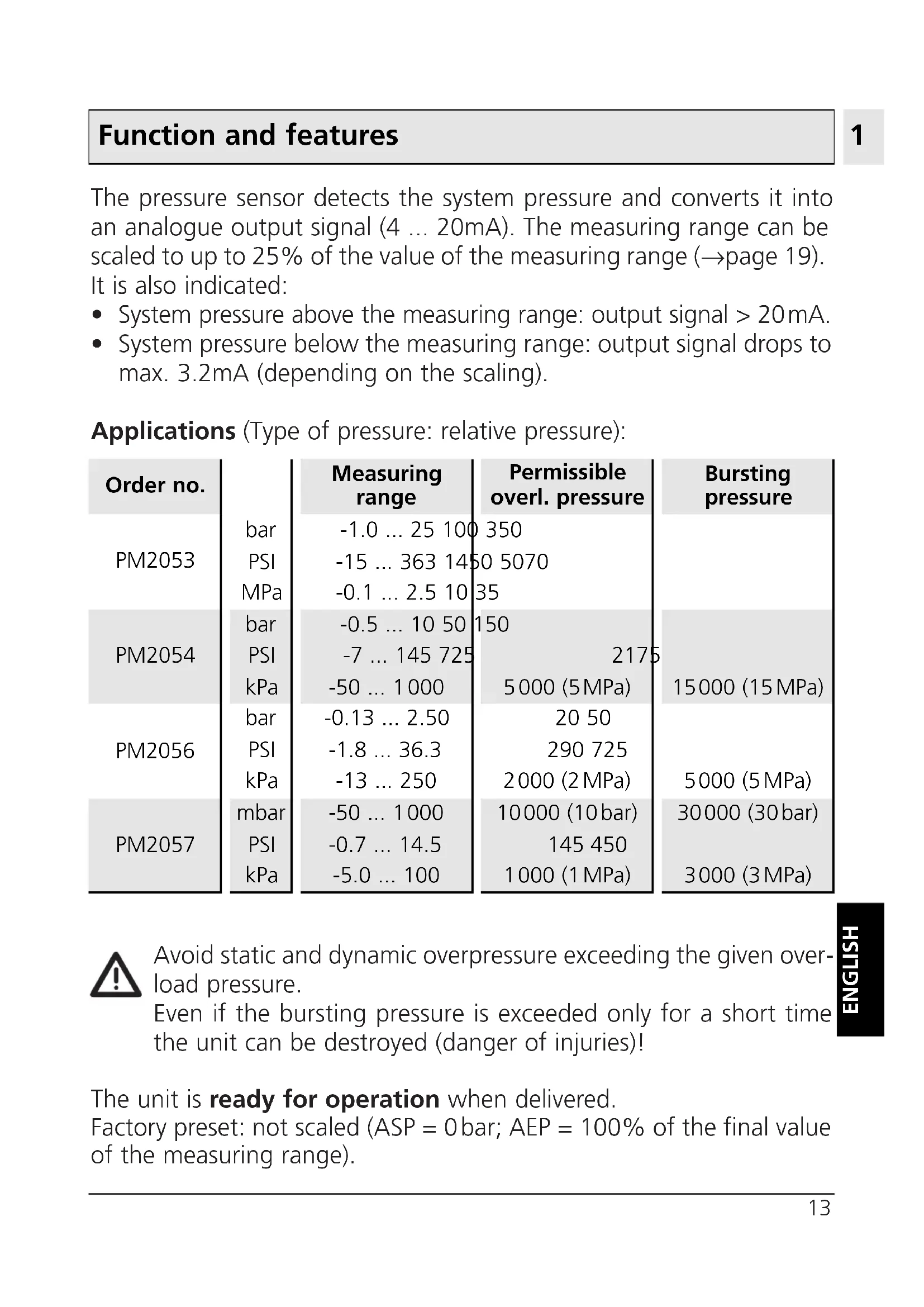
- System pressure above the measuring range: output signal > 20mA.
- System pressure below the measuring range: output signal drops to max. 3.2mA (depending on the scaling). Applications (Type of pressure: relative pressure): Avoid static and dynamic overpressure exceeding the given over- load pressure. Even if the bursting pressure is exceeded only for a short time the unit can be destroyed (danger of injuries)! The unit is ready for operation when delivered. Factory preset: not scaled (ASP = 0bar; AEP = 100% of the final value of the measuring range).
- ENGLISH Function and features Bursting pressure Permissible overl. pressure Measuring range Order no. PM2053 -1.0 p. 25
- 100 350 -15 p. 363
- 1450 5070 -0.1 p. 2
- .5 10 35 bar PSI MPa bar PSI kPa bar PSI kPa mbar PSI kPa PM2054 -0.5 p. 10
- 50 150 -7 p. 145
- 725 2175 -50 p. 1000
- 5000 (5MPa) 15000 (15MPa) PM2056 -0.13 p. 2
- .50 20 50 -1.8 p. 36
- .3 290 725 -13 p. 250
- 2000 (2MPa) 5000 (5MPa) PM2057 -50 p. 1000
- 10000 (10bar) 30000 (30bar) -0.7 p. 14
- .5 145 450 -5.0 1000 (1MPa) 3000 (3MPa)Installation Before mounting and removing the sensor, make sure that no pressure is applied to the system. The unit is adaptable for various process fittings. ifm adapters to be ordered separately as acces- sories. Mount adapter (B) to the sensor first, then sensor + adapter to the process connection by means of a nut, a clamping flange or similar (A). If it is not possible to slide the fix- ing element (A) down over the top of the sensor: slide it up over the bottom of the sensor before the adapter is mounted. Note: Sensor and adapter are only to be mounted once. Mounting of the adapter Step 1 Grease thread and sealing cham- fer of the sensor and of the adapter with the greasing paste supplied. The greasing paste is food-grade (USDA-H1 84-201). Make sure that the O-ring (C) is correctly positioned. p. 100
Grease Use with factory settingStep 2 Screw the sensor into the adapter. Avoid mechanical influ- ence on the sealing chamfers. Step 3 Clamp sensor and adapter into a clamping device (D). The sealing chamfers (E) must not be dam- aged. Tighten the sensor with a spanner until you can feel the end stop. Note: If you continue to turn, this can have adverse effect on the sealing. Electrical connection The unit must be connected by a suitably qualified electrician. The national and international regulations for the installation of electrical equipment must be observed. Voltage supply to EN50178, SELV, PELV. Disconnect power before connecting the unit as follows:
ENGLISH Core colours of ifm sockets: 1 = BN (brown), 2 = WH (white),3 = BU (blue), 4 = BK (black); n.c. = not connected.
n.c. Connector view (sensor) 2 wire connection 3 wire connection
IInstallation and set-up / operation / maintenance After mounting, wiring and setting check whether the unit operates correctly. Cleaning of the filter cover If viscous and residues producing media clog the filter cover of the sensor (and thus reduce the mea- suring accuracy slightly), you can clean it. Unscrew the filter cover (B) (use a pair of pliers with plastic-covered jaws for this). Clean the cover thoroughly. The vent (A) should only be clea- ned by skilled personnel and with utmost care. Possible medium residues must not be compressed and pressed into the vent. This could clog the filter system and reduce the measuring accuracy of the sensor. Screw the filter cover again tightly. The sensor is sufficiently protected against harsh ambient conditions (protection IP 67). The protection rating can be increased by a special accessory (order no. E30043).
- The sensor is supplied with operating voltage by the interface,
- and transmits its data (measured values, analogue signal and para- meter settings) continuously via the interface. It provides the following options:
- Remote display Indication of the current system pressure by PC or display.
- Remote evaluation Output of the current analogue value.
- Programming / remote programming of the sensor Scaling the measuring range, damping for the analogue output, calibration of the sensor. Parameters can be set before the sensor is mounted and set up or during operation. If you change the parameters during operation, the functioning of the plant will be affected. Ensure that plant malfunction is prevented.
EPS RS232 interface PCWiring of sensor and EPS interface For use of the sensor with EPS interface prior to installation of the sen- sor: Use a suitable power supply (24V power supply; ifm order no. E30080). For mobile use of the interface after installation of the sensor: Disconnect power before connecting the unit. Do not disconnect these connections while live. Programming A service program for the PC which is easy to use and self-explanatory (order no. E30069) is available for the programming of the sensor.
Core colours of ifm sockets: 1 = BN (brown), 2 = WH (white), 3 = BU (blue), 4 = BK (black). n.c. = not connected RS232
ENGLISH Technical information / Functioning / Parameters Analogue start point Measured value at which 4mA is provided. Analogue end point Measured value at which 20mA is provided. Minimum distance between ASP and AEP = 25% of the span. Setting range: → page 33. Calibration offset The internal measured value (operating value of the sensor) is offset against the real measured value.
- Setting range: -5 ... +5% of the value of the span (with scaling as factory setting (ASP = 0bar and AEP = final value of measuring range),
- in steps of 0.1% of the value of the span. Calibration reset Resets the calibration set by COF. Min-Max memory for system pressure
- HI: displays the highest measured pressure.
- LO: displays the lowest measured pressure. Damping for the analogue output Pressure peaks of short duration or high frequency can be filtered out. dAA-value = response time between pressure change and change of the switching status in milliseconds (ms).
- setting range: 0 (= dAA is not active) / 0.1s / 0.5s / 2s. Display unit The measured values and values for ASP / AEP can be indicated in the following units: bAr (= bar / mbar), PSI, PA (= MPa / kPa). Select the display unit before setting the limits for the analogue output signal (ASP, AEP). This avoids rounding errors generated internally during the conversion of the units and enables exact setting of the limits for the analogue output signal. ASP AEP
- Characteristics deviation (linearity, incl. hysteresis and repeatability
all indications are referred to a turn down of 1:1
limit value setting to DIN 16086 Setting of the display d1 / d2 / d3 = update of the measured value every 50ms / 200ms / 600ms. The update interval only refers to the display. ph = display of the measured peak value remains for a short time (peak hold). rotated = display rotated 180°. OFF = in the Run mode the display of the measured value is deactivated. diSScaling the measuring range
- With the parameter "Analogue start point" (ASP) the measured value at which the output signal is 4mA is defined.
- With the parameter "Analogue end point" (AEP) the measured value at which the output signal is 20mA is defined.
- Minimum distance between ASP and AEP = 25 % of the span (scal- ing factor 4). The output signal is between 4 and 20mA in the set measuring range. It is also indicated:
- System pressure above the measuring range: output signal > 20mA.
- System pressure below the measuring range: output signal drops to max. 3.2mA (depending on the scaling).
MEW (AEP) 0 (ASP)-1 I [mA]
MEW (AEP) 0 (ASP)-1 I [mA]