PN3050 - Sensor IFM - Free user manual and instructions
Find the device manual for free PN3050 IFM in PDF.
Download the instructions for your Sensor in PDF format for free! Find your manual PN3050 - IFM and take your electronic device back in hand. On this page are published all the documents necessary for the use of your device. PN3050 by IFM.
USER MANUAL PN3050 IFM
Safety instructions Please read the product description prior to installing the unit. Please check that the product is suitable for your application without any restrictions. If the operating instructions or the technical data are not adhered to, personal injury and/or damage to property may occur. Please check in all applications that the product materials (see Technical data) are compatible with the media to be mea- sured. For gaseous media the application is limited to max. 25bar.1. Function and features
- The pressure sensor detects the system pressure,
- shows the current system pressure on its display (indication as from 1% to 105% of the value of the measuring range),
- and generates 2 output signals according to the set output configuration. Applications Type of pressure: relative pressure Avoid static and dynamic overpressure exceeding the given over- load pressure. For gaseous media the application is limited to max. 25bar. Even if the bursting pressure is exceeded only for a short time the unit can be destroyed (danger of injuries)! Indication of the current system pressure as from 1% of the value of the measuring range. Display "0" does not mean that the system is free of pressure!
- ENGLISH output 1 hysteresis function / N.O. (Hno) hysteresis function / N.C. (Hnc) window function / N.O. (Fno) window function / N.C. (Fnc) output 2 analog 4 p. 20
- mA Bursting pressure Permissible overl. pressure Measuring range Order no. PN3050 0 p. 400
- bar 600 bar 1000 bar PN3051 0 p. 250
- bar 400 bar 850 bar PN3052 0 p. 100
- bar 300 bar 650 bar PN3053 0 p. 25
- bar 100 bar 350 bar PN3054 0 p. 10
- bar 50 bar 150 bar PN3056 0 p. 2
- .5 bar 20 bar 50 bar PN3057 0 bar 10 bar 30 barHysteresis: The hysteresis keeps the switch- ing state of the output stable if the system pressure varies about the preset value. When the sys- tem pressure is rising, the output switches when the switch-on point has been reached (SP1); when the system pressure is falling again, the output switches back when the switch-off point (rP1) has been reached. The hysteresis can be set: First the switch-on point is set, then the switch-off point with the requested difference. Window function: The window function enables the monitoring of a defined acceptable range. When the sys- tem pressure varies between the switch-on point (SP1) and the switch-off point (rP1), the output is switched (window function / NO) or not switched (window function / NC). The width of the window can be set by means of the difference between SP1 and rP1. SP1 = upper value, rP1 = lower value. p. 1
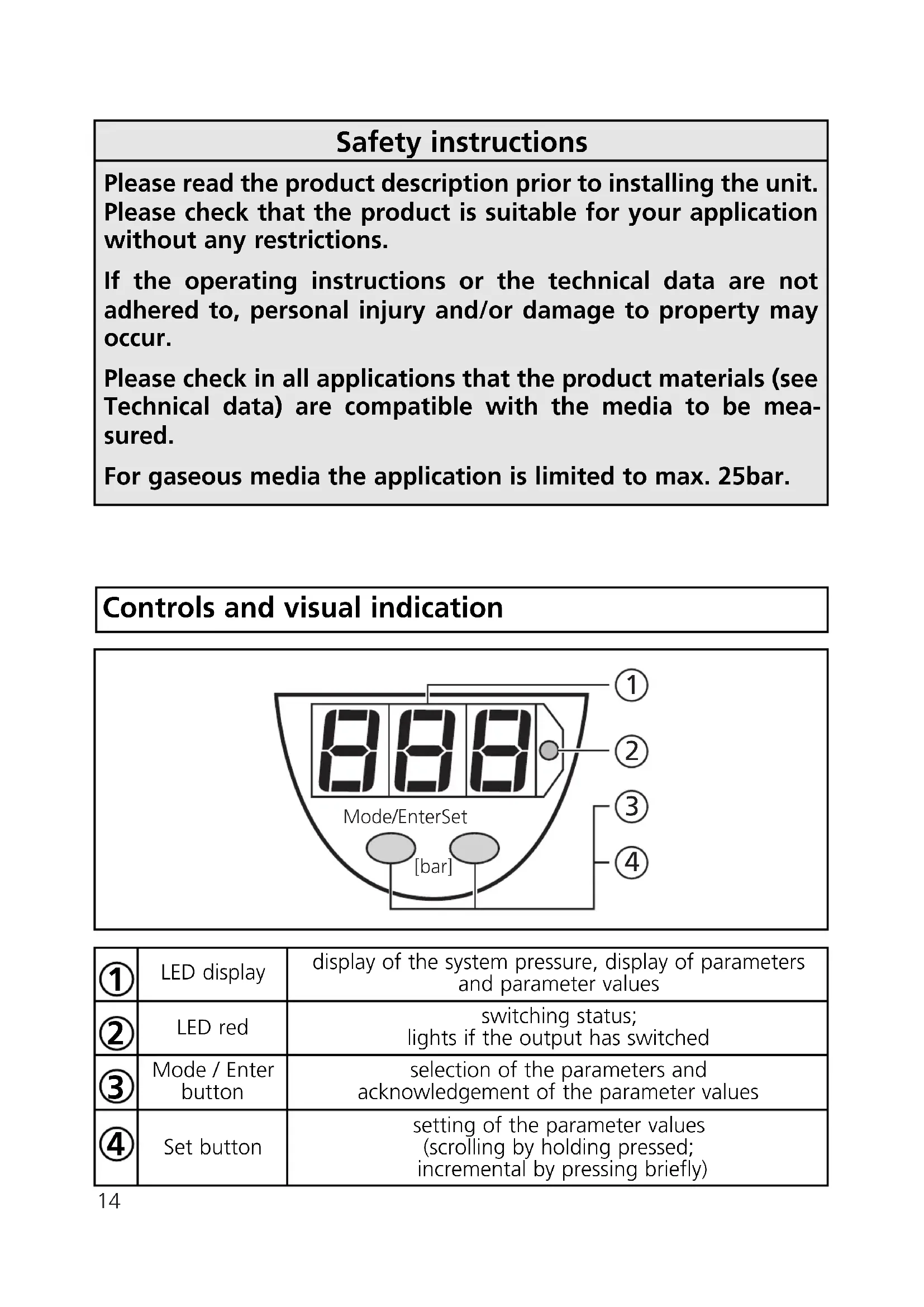
Hno hysteresis Hnc Fno acceptable range Fnc2. Operating modes Run mode: (Normal operating mode) When the supply voltage has been applied, the unit is in the Run mode. It monitors and switches the transistor output according to the set parameters. The value of the analog output depends on the system pressure. The display shows the current system pressure, the red LED indicates the switching state of the output. Display mode: (Indication of parameters and the set parameter values) When the "Mode/Enter" button is pressed briefly, the unit passes to the Display mode which allows parameter values to be read. The inter- nal sensing, processing and output functions of the unit continue as if in Run mode.
- The parameter names are scrolled with each pressing of the "Mode/Enter" button.
- When the "Set" button is pressed briefly, the corresponding para- meter value is displayed for 5s. After another 5s the unit returns to the Run mode. Programming mode: (Setting of the parameter values) The unit passes to the programming mode when after the selection of a parameter value (Display mode) the "Set" button is pressed until the display of the parameter value is changed. Internally the unit remains in the operating mode. It continues its monitoring function with the existing parameters until the change has been terminated. You can change the parameter value by pressing the "Set" button and confirm it by pressing the "Mode/Enter" button. The unit returns to the Run mode when no button has been pressed for 5s.
Switch-on point: Upper limit value at which the output changes its switching status.
- setting range 1 ... 100% of the value of the measuring range
- in steps of 0.5% of the value of the measuring range
- indicated in bar Delay time for the switching output dS1 = switch-on delay; dr1 = switch-off delay The output does not immediately change its switching status when the switching condition is met but when the delay time has elapsed. If the switching condition is no longer met when the delay time has elapsed, the switching state of the output does not change.
- setting range: 0 - 0.2 - 0.4 ... 9.8 - 10 - 11 - ... - 49 - 50s
- in steps of 0.2 or 1s
- indicated in seconds Switching functions of the switching output 4 settings can be selected: Hno = hysteresis / normally open Hnc = hysteresis / normally closed Fno = window function / normally open Fnc = window function / normally closed Switch-off point: Lower limit value at which the output changes its switching status.
- setting range 0.5 ... 99.5% of the value of the measuring range
- in steps of 0.5% of the value of the measuring range
- indicated in bar rP1 is always lower than SP1. The unit only accepts values which are 0.5% lower than SP1. Changing the switch-on point also changes the switch-off point (the distance between SP1 and rP1 remains constant). If the distance is higher than the new switch point, it is automati- cally reduced (rP1 is set to the minimum setting value).4. Installation Before mounting and removing the sensor, make sure that no pressure is applied to the system. Mount the pressure sensor on a suitable process connection (see type label “Port Size”).
5. Electrical connection
The unit must only be connected by an electrician. The national and international regulations for the installation of electrical equipment must be observed. Voltage supply to EN50178, SELV, PELV. Disconnect power before connecting the unit. Wiring:
Damping for the switching output Pressure peaks of short duration or high frequency can be filtered out. dAP-value = response time between pressure change and change of the switching status in ms.
- the value for dAP defines the switching frequency (f) of the output: dAP f [Hz]
Core colours of ifm sockets: 1 = BN (brown), 2 = WH (white), 3 = BU (blue), 4 = BK (black).6. Programming Take the following 3 steps for programming: If no button is pressed for 20s during the setting procedure, the unit returns to the operating mode. Locking / Unlocking The unit can be electronically locked to prevent unwanted adjustment of the set parameters: Press (in Run mode) both pushbuttons for 10s. As soon as the indication goes out the unit is locked or unlocked. Units are delivered from the factory in the unlocked state. With the unit in the locked state is indicated briefly when you try to change parameter values.
Mode/Enter Set Mode/Enter Set Mode/Enter Set Press the Mode/Enter button several times until the respective parameter is displayed. Press the Set button and keep it pressed. The current parameter value is indicated for 5s, then the value is increased* (incremental by pressing briefly or scrolling by holding pressed). Press the Mode/Enter button briefly (= acknowledgement). The parameter is displayed again, the set parameter value becomes effective.
*Decrease the value: Let the display of the parameter value move to the maximum setting value. Then the cycle starts again at the minimum setting value. Wait 5s (the unit passes to the operating mode and the current measured value is indicated again), or start again with step 1 to program other parameters.7. Installation and set-up / Operation After mounting, wiring and setting check whether the unit operates correctly. Faults displayed during operation:
57,3 M12x1 7-segment display programming button process connection = overload pressure (system pressure > 110% of the max. nominal pressure) (flashing) = short-circuit in the switching output; the output is switched off9. Technical data